EP1340902B1 - Gasturbine mit gegenläufigen Niederdruckrotoren - Google Patents
Gasturbine mit gegenläufigen Niederdruckrotoren Download PDFInfo
- Publication number
- EP1340902B1 EP1340902B1 EP02258821A EP02258821A EP1340902B1 EP 1340902 B1 EP1340902 B1 EP 1340902B1 EP 02258821 A EP02258821 A EP 02258821A EP 02258821 A EP02258821 A EP 02258821A EP 1340902 B1 EP1340902 B1 EP 1340902B1
- Authority
- EP
- European Patent Office
- Prior art keywords
- low pressure
- turbine
- fan
- high pressure
- aft
- Prior art date
- Legal status (The legal status is an assumption and is not a legal conclusion. Google has not performed a legal analysis and makes no representation as to the accuracy of the status listed.)
- Expired - Lifetime
Links
Images


Classifications
-
- F—MECHANICAL ENGINEERING; LIGHTING; HEATING; WEAPONS; BLASTING
- F02—COMBUSTION ENGINES; HOT-GAS OR COMBUSTION-PRODUCT ENGINE PLANTS
- F02K—JET-PROPULSION PLANTS
- F02K3/00—Plants including a gas turbine driving a compressor or a ducted fan
- F02K3/02—Plants including a gas turbine driving a compressor or a ducted fan in which part of the working fluid by-passes the turbine and combustion chamber
- F02K3/04—Plants including a gas turbine driving a compressor or a ducted fan in which part of the working fluid by-passes the turbine and combustion chamber the plant including ducted fans, i.e. fans with high volume, low pressure outputs, for augmenting the jet thrust, e.g. of double-flow type
- F02K3/072—Plants including a gas turbine driving a compressor or a ducted fan in which part of the working fluid by-passes the turbine and combustion chamber the plant including ducted fans, i.e. fans with high volume, low pressure outputs, for augmenting the jet thrust, e.g. of double-flow type with counter-rotating, e.g. fan rotors
-
- F—MECHANICAL ENGINEERING; LIGHTING; HEATING; WEAPONS; BLASTING
- F01—MACHINES OR ENGINES IN GENERAL; ENGINE PLANTS IN GENERAL; STEAM ENGINES
- F01D—NON-POSITIVE DISPLACEMENT MACHINES OR ENGINES, e.g. STEAM TURBINES
- F01D11/00—Preventing or minimising internal leakage of working-fluid, e.g. between stages
- F01D11/001—Preventing or minimising internal leakage of working-fluid, e.g. between stages for sealing space between stator blade and rotor
-
- F—MECHANICAL ENGINEERING; LIGHTING; HEATING; WEAPONS; BLASTING
- F01—MACHINES OR ENGINES IN GENERAL; ENGINE PLANTS IN GENERAL; STEAM ENGINES
- F01D—NON-POSITIVE DISPLACEMENT MACHINES OR ENGINES, e.g. STEAM TURBINES
- F01D25/00—Component parts, details, or accessories, not provided for in, or of interest apart from, other groups
- F01D25/16—Arrangement of bearings; Supporting or mounting bearings in casings
-
- F—MECHANICAL ENGINEERING; LIGHTING; HEATING; WEAPONS; BLASTING
- F01—MACHINES OR ENGINES IN GENERAL; ENGINE PLANTS IN GENERAL; STEAM ENGINES
- F01D—NON-POSITIVE DISPLACEMENT MACHINES OR ENGINES, e.g. STEAM TURBINES
- F01D25/00—Component parts, details, or accessories, not provided for in, or of interest apart from, other groups
- F01D25/18—Lubricating arrangements
-
- F—MECHANICAL ENGINEERING; LIGHTING; HEATING; WEAPONS; BLASTING
- F01—MACHINES OR ENGINES IN GENERAL; ENGINE PLANTS IN GENERAL; STEAM ENGINES
- F01D—NON-POSITIVE DISPLACEMENT MACHINES OR ENGINES, e.g. STEAM TURBINES
- F01D25/00—Component parts, details, or accessories, not provided for in, or of interest apart from, other groups
- F01D25/24—Casings; Casing parts, e.g. diaphragms, casing fastenings
-
- F—MECHANICAL ENGINEERING; LIGHTING; HEATING; WEAPONS; BLASTING
- F01—MACHINES OR ENGINES IN GENERAL; ENGINE PLANTS IN GENERAL; STEAM ENGINES
- F01D—NON-POSITIVE DISPLACEMENT MACHINES OR ENGINES, e.g. STEAM TURBINES
- F01D9/00—Stators
- F01D9/02—Nozzles; Nozzle boxes; Stator blades; Guide conduits, e.g. individual nozzles
- F01D9/04—Nozzles; Nozzle boxes; Stator blades; Guide conduits, e.g. individual nozzles forming ring or sector
- F01D9/041—Nozzles; Nozzle boxes; Stator blades; Guide conduits, e.g. individual nozzles forming ring or sector using blades
-
- F—MECHANICAL ENGINEERING; LIGHTING; HEATING; WEAPONS; BLASTING
- F02—COMBUSTION ENGINES; HOT-GAS OR COMBUSTION-PRODUCT ENGINE PLANTS
- F02C—GAS-TURBINE PLANTS; AIR INTAKES FOR JET-PROPULSION PLANTS; CONTROLLING FUEL SUPPLY IN AIR-BREATHING JET-PROPULSION PLANTS
- F02C3/00—Gas-turbine plants characterised by the use of combustion products as the working fluid
- F02C3/04—Gas-turbine plants characterised by the use of combustion products as the working fluid having a turbine driving a compressor
- F02C3/06—Gas-turbine plants characterised by the use of combustion products as the working fluid having a turbine driving a compressor the compressor comprising only axial stages
- F02C3/067—Gas-turbine plants characterised by the use of combustion products as the working fluid having a turbine driving a compressor the compressor comprising only axial stages having counter-rotating rotors
-
- F—MECHANICAL ENGINEERING; LIGHTING; HEATING; WEAPONS; BLASTING
- F02—COMBUSTION ENGINES; HOT-GAS OR COMBUSTION-PRODUCT ENGINE PLANTS
- F02C—GAS-TURBINE PLANTS; AIR INTAKES FOR JET-PROPULSION PLANTS; CONTROLLING FUEL SUPPLY IN AIR-BREATHING JET-PROPULSION PLANTS
- F02C7/00—Features, components parts, details or accessories, not provided for in, or of interest apart form groups F02C1/00 - F02C6/00; Air intakes for jet-propulsion plants
- F02C7/20—Mounting or supporting of plant; Accommodating heat expansion or creep
-
- F—MECHANICAL ENGINEERING; LIGHTING; HEATING; WEAPONS; BLASTING
- F05—INDEXING SCHEMES RELATING TO ENGINES OR PUMPS IN VARIOUS SUBCLASSES OF CLASSES F01-F04
- F05D—INDEXING SCHEME FOR ASPECTS RELATING TO NON-POSITIVE-DISPLACEMENT MACHINES OR ENGINES, GAS-TURBINES OR JET-PROPULSION PLANTS
- F05D2240/00—Components
- F05D2240/55—Seals
- F05D2240/56—Brush seals
-
- Y—GENERAL TAGGING OF NEW TECHNOLOGICAL DEVELOPMENTS; GENERAL TAGGING OF CROSS-SECTIONAL TECHNOLOGIES SPANNING OVER SEVERAL SECTIONS OF THE IPC; TECHNICAL SUBJECTS COVERED BY FORMER USPC CROSS-REFERENCE ART COLLECTIONS [XRACs] AND DIGESTS
- Y02—TECHNOLOGIES OR APPLICATIONS FOR MITIGATION OR ADAPTATION AGAINST CLIMATE CHANGE
- Y02T—CLIMATE CHANGE MITIGATION TECHNOLOGIES RELATED TO TRANSPORTATION
- Y02T50/00—Aeronautics or air transport
- Y02T50/60—Efficient propulsion technologies, e.g. for aircraft
Definitions
- the invention relates to aircraft gas turbine engines with counter rotating low pressure turbine rotors and, particularly, for such engines having inter-turbine frames that support the counter rotating low pressure turbine rotors in bearings and are used to mount the engines to the aircraft.
- a gas turbine engine of the turbofan type generally includes a forward fan and booster compressor, a middle core engine, and an aft low pressure power turbine.
- the core engine includes a high pressure compressor, a combustor and a high pressure turbine in a serial flow relationship.
- the high pressure compressor and high pressure turbine of the core engine are interconnected by a high pressure shaft.
- the high pressure compressor, turbine, and shaft essentially form the high pressure rotor.
- the high pressure compressor is rotatably driven to compress air entering the core engine to a relatively high pressure. This high pressure air is then mixed with fuel in the combustor and ignited to form a high energy gas stream.
- the gas stream flows aft and passes through the high pressure turbine, rotatably driving it and the high pressure shaft which, in turn, rotatably drives the compressor.
- the gas stream leaving the high pressure turbine is expanded through a second or low pressure turbine.
- the low pressure turbine rotatably drives the fan and booster compressor via a low pressure shaft, all of which form the low pressure rotor.
- the low pressure shaft extends through the high pressure rotor.
- Some low pressure turbines have been designed with counter rotating turbines that power counter rotating fans and booster or low pressure compressors.
- U.S. Patent Nos. 4,860,537 , 5,307,622 and 4,790,133 disclose counter rotating turbines that power counter rotating fans and booster or low pressure compressors. Most of the thrust produced is generated by the fan.
- Engine frames including fan and turbine frames are used to support and carry the bearings which; in turn, rotatably support the rotors. Bearing support frames are heavy and add weight, length, and cost to the engine.
- an aircraft gas turbine engine assembly includes a high pressure rotor including a high pressure turbine, a low pressure turbine having counter rotating low pressure inner and outer rotors located aft of the high pressure rotor, and an inter-turbine frame axially located between the high and low pressure turbines.
- the low pressure inner and outer rotors including low pressure inner and outer shafts which are at least in part rotatably disposed co-axially with and radially inwardly of the high pressure rotor.
- the inter-turbine frame has a first structural ring, a second structural ring disposed co-axially with and radially spaced inwardly of the first structural ring about a centerline, and a plurality of circumferentially spaced apart struts extending radially between the first and second structural rings.
- Forward and aft sump members having forward and aft central bores respectively, are fixedly joined to axially spaced apart forward and aft portions of the inter-turbine frame by forward and aft bearing support structures, respectively.
- the low pressure inner and outer rotors are rotatably supported by an aftwardmost low pressure rotor support bearing mounted in the aft central bore of the aft sump member.
- the high pressure rotor is aftwardly radially rotatably supported by a fifth bearing mounted in the forward bearing support structure.
- a frame connecting means for connecting the engine to an aircraft is located on the first structural ring.
- the connecting means includes at least one U-shaped clevis.
- An outlet guide vane assembly supports a row of outlet guide vanes that extend radially between a low pressure turbine casing structurally connected to the inter-turbine frame and an annular box structure.
- a cover plate is bolted to the annular box structure.
- a rotatable annular outer drum rotor is drivingly connected to a first fan blade row and a first booster by the low pressure inner shaft.
- a rotatable annular inner drum rotor is drivingly connected to a second fan blade row and a second booster by the low pressure outer shaft, the first and second boosters are axially located between the first and second fan blade rows.
- a bypass duct radially bounded by a fan casing and an annular radially inner bypass duct wall surrounds the first and second boosters and a radially outer portion of the second fan blade row is radially disposed within the bypass duct.
- the engine assembly has a fan inlet hub to tip radius ratio in a range between .20 and .35, a bypass ratio in a range of 5-15, an operational fan pressure ratio in a range of 1.4 - 2.5, and a sum of operational fan tip speeds of the first and second fan blade rows in a range of 1000 to 2500 feet per second.
- the high pressure compressor is designed and operable to produce a compressor pressure ratio in a range of about 15-30 and overall pressure ratio in a range of about 40-65.
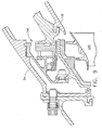
- FIG. 1 Further embodiments of the invention include a second seal in sealing arrangement between forward ends of the low pressure turbine casing and the outer drum rotor, a third seal in sealing arrangement between the low pressure turbine casing and a final stage of the low pressure turbine blade rows which is bolted to an aft end of the outer drum rotor, and a first seal in sealing arrangement between the second fan and the fan frame.
- the seals are brush seals, however in other embodiments the seals may be non-contacting seals or a combination of brush seals and non-contacting seals. The non-contacting seals may be aspirating seals or face seals.
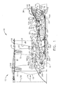
- FIG. 1 Illustrated schematically in FIG. 1 is a first exemplary turbofan gas turbine engine 10 circumscribed about an engine centerline 8 and having a fan section 12 which receives inlet airflow of ambient air 14.
- the fan section 12 has counter rotating first and second fans 4 and 6 including first and second fan blade rows 13 and 15 and counter rotating first and second boosters 16 and 17, respectively.
- the counter rotating first and second boosters 16 and 17 are axially located between the counter rotating first and second fan blade rows 13 and 15, an arrangement which provides reduced noise emanating from the fan section 12.
- HPC high pressure compressor
- HPC high pressure compressor
- HPC high pressure turbine
- LPT counter rotating low pressure turbine
- the engine 10 is designed such that the last stage of the second booster 17 and, in the exemplary embodiment, the second fan blade row 15 are counter rotatable with respect to the high pressure compressor 18. This reduces the sensitivity of the engine 10 to airflow inlet distortion of the fan section 12. It also reduces mutual sensitivity to rotating stall cells in the other rotors.
- a high pressure shaft 27 joins the HPT 24 to the HPC 18 to substantially form a first or high pressure rotor 33.
- the high pressure compressor 18, combustor 20, and high pressure turbine 24 collectively are referred to as a core engine 25 which includes, for the purposes of this patent, the high pressure shaft 27.
- the core engine 25 is modular such that as a single unit it can be independently replaced separate from the other parts of the gas turbine.
- a bypass duct 21 radially, bounded by a fan casing 11 and a rotatable annular radially inner bypass duct wall 9, surrounds the counter rotating first and second boosters 16 and 17 and an inlet duct 19 to the high pressure compressor 18 of the core engine 25.
- the bypass duct 21 is radially bounded by a fan casing 11 and an annular radially inner bypass duct wall 9.
- the radially inner bypass duct wall 9 includes a rotatable wall section 22 fixedly mounted to the second fan blade row 15 and from which the second booster 17 depends radially inwardly.
- a radially outer portion 23 of the second fan blade row 15 is radially disposed within the bypass duct 21.
- the counter rotating low pressure turbine 26 includes an annular outer drum rotor 136 rotatably mounted to a low pressure inner shaft 130 by an aft low pressure inner conical shaft extension 132.
- the outer drum rotor 136 includes a plurality of low pressure turbine blade rows 138 extending radially inwardly therefrom and axially spaced from each other.
- the drum rotor 136 is cantilevered off of a final stage 139 of the low pressure turbine blade rows 138 which is bolted to the aft low pressure inner conical shaft extension 132.
- the counter rotating low pressure turbine 26 also includes an annular low pressure inner drum rotor 146 rotatably mounted to a low pressure outer shaft 140 by an aft low pressure outer conical shaft extension 142.
- the inner drum rotor 146 includes a plurality of second low pressure turbine blade rows 148 extending radially outwardly therefrom and axially spaced from each other.
- the first low pressure turbine blade rows 138 are interdigitated with the second low pressure turbine blade rows 148.
- the low pressure outer shaft 140 drivingly connects the inner drum rotor 146 to the second fan blade row 15 and the second booster 17.
- the second fan blade row 15 is connected to the low pressure outer shaft 140 by a forward conical outer shaft extension 143.
- the low pressure outer shaft 140, the inner drum rotor 146, the second fan blade row 15, and the second booster 17 are major components of a low pressure outer rotor 202.
- the low pressure inner shaft 130 drivingly connects the outer drum rotor 136 to the first fan blade row 13 and the first booster 16.
- the first fan blade row 13 is connected to the low pressure inner shaft 130 by a forward conical inner shaft extension 133.
- the low pressure inner shaft 130, the outer drum rotor 136, the first fan blade row 13, and the first booster 16 are major components of a low pressure inner rotor 200.
- the first booster 16 includes an annular first booster rotor section 166 including the rotatable wall section 22 from which axially spaced apart first booster blade rows 168 extend radially inwardly.
- the annular first booster rotor section 166 is illustrated as being integrally bladed in a manner similar to an integrally bladed disk, commonly referred to as a Blisk, or an integrally bladed rotor which has been used in conventional rotors because they are lightweight and allow no blade attachment leakage.
- the operating low speeds of the boosters and the low weight integrally bladed disk design of the first booster rotor section 166 helps minimize stresses and deflections of the first booster rotor section 166.
- the second booster 17 includes an annular second booster rotor section 170 from which axially spaced apart second booster blade rows 172 extend radially outwardly.
- a radially inner portion 28 of the second fan blade row 15 is radially disposed within the inlet duct 19 and rotates with the second booster 17 and therefore is considered part of the second booster 17 and a second booster blade row 172.
- the first and second booster blade rows 168 and 172 are interdigitated and are counter rotating.
- the first and second fan blade rows 13 and 15 are fixedly attached to the first and second booster rotor sections 166 and 170, respectively.
- the low pressure inner and outer shafts 130 and 140, respectively, are at least, in part, rotatably disposed co-axially with and radially inwardly of the high pressure rotor 33.
- the engine 10 has frame structure 32 including a forward or fan frame 34 connected by an engine casing 45 to a mid-engine or inter-turbine frame 60.
- the second fan blade row is axially located close to struts 35 of the fan frame 34 and so the leading edges of struts 35 are swept or leaned axially aftwardly to reduce noise.
- the engine 10 is mounted within or to an aircraft such as by a pylon (not illustrated) which extends downwardly from an aircraft wing.
- the inter-turbine frame 60 includes a first structural ring 86, which may be a casing, disposed co-axially about the centerline 8.
- the inter-turbine frame 60 further includes a second structural ring 88 disposed co-axially with and radially spaced inwardly of the first structural ring 86 about the centerline 8.
- the second structural ring 88 may also be referred to as a hub.
- a plurality of circumferentially spaced apart struts 90 extend radially between the first and second rings 86 and 88 and are fixedly joined thereto.
- the struts 90 are hollow in the exemplary embodiment of the invention illustrated herein but, in other embodiments, the struts may not be hollow.
- inter-turbine frame 60 is axially located between the HPT 24 and the LPT 26 of the high pressure rotor 33 and the low pressure inner and outer rotors 200 and 202, it is referred to as an inter-turbine frame also sometimes referred to as a mid-engine frame.
- An inter-turbine transition duct 114 between the HPT 24 and the LPT 26 passes through the inter-turbine frame 60.
- the engine is mounted to the aircraft at a forwardly located fan frame forward mount 118 on the fan frame 34 and at an aftwardly located turbine frame aft mount 120 on the inter-turbine frame 60.
- the engine 10 may be mounted below an aircraft wing by a pylon at the forward mount 118 and the aft mount 120 spaced axially downstream from the forward mount 118.
- the aft mount 120 is used to fixedly join the inter-turbine frame 60 to a platform which is fixedly joined to the pylon.
- the aft mount 120 includes a U-shaped clevis 122.
- U-shaped clevises 122 Conventional mounts often use a set of circumferentially spaced apart U-shaped clevises 122 (only one of the U-shaped clevises is shown in the cross-sectional illustrations in the FIGS.) on the inter-turbine frame 60.
- the U-shaped clevises 122 are designed to be connected by a set of pins to a set of links. The links are connected to a platform on the bottom of the pylon.
- the U-shaped clevises 122 are one type of frame connecting means for connecting the engine to an aircraft. Other types of mounting means besides clevises are known in the aircraft industry and can be utilized to mount the frame of the present invention and the engine to the aircraft.
- the low pressure outer rotor 202 by way of the forward conical outer shaft extension 143, is rotatably supported axially and radially from the fan frame 34 by an aft thrust bearing 43 mounted in a first bearing support structure 44 and a second bearing 36, a roller bearing, mounted in a second bearing support structure 47.
- the low pressure inner rotor 200 by way of the forward conical inner shaft extension 133, is rotatably supported axially and radially from the fan frame 34 by a forward differential thrust bearing 55 which is mounted between a forwardly extending extension 56 of the forward conical outer shaft extension 143 and the forward conical inner shaft extension 133.
- the low pressure inner rotor 200 is further rotatably supported radially from the fan frame 34 by a forward differential bearing 208, a roller bearing, between the low pressure inner shaft 130 and the low pressure outer shaft 140.
- the first and second bearing support structures 44 and 47 are fixedly attached to the fan frame 34.
- the low pressure outer rotor 202 by way of the aft low pressure outer conical shaft extension 142 connected to the low pressure outer shaft 140, is rotatably supported radially by a third bearing 76 within the inter-turbine frame 60.
- the third bearing 76 is disposed between an aft bearing support structure 97 attached to an aft portion 110 of the inter-turbine frame 60 and a forward inner extension 190 of the aft low pressure outer conical shaft extension 142.
- the low pressure outer rotor 202 is most aftwardly rotatably supported by the third bearing 76 which is thus referred to as an aftwardmost low pressure rotor support bearing.
- the inter-turbine frame 60 of the present invention is axially located between the HPT 24 and the LPT 26 and thus substantially supports the entire low pressure turbine 26.
- the low pressure inner rotor 200 by way of the aft low pressure inner conical shaft extension 132 connected to the low pressure inner shaft 130, is rotatably supported radially by the aft low pressure outer conical shaft extension 142 of the low pressure outer rotor 202.
- a differential bearing 144 (also referred to as an inter-shaft bearing) is disposed between an aft inner extension 192 of the aft low pressure outer conical shaft extension 142 and an outer extension 194 of the aft low pressure inner conical shaft extension 132. This allows the low pressure inner and outer rotors 200 and 202 to counter rotate.
- a forward high pressure end 70 of the high pressure compressor 18 of the high pressure rotor 33 is radially rotatably supported by a bearing assembly 80 mounted in a bearing assembly support structure 82 attached to the fan frame 34.
- an aft end 92 of the high pressure rotor 33 is aftwardly radially rotatably supported by a fifth bearing 94 mounted in a forward bearing support structure 96 attached to a forward portion 108 of the inter-turbine frame 60.
- the forward and aft bearing support structures 96 and 97 which are fixedly joined or attached to the forward and aft portions 108 and 110, respectively, of the inter-turbine frame 60 and thus are spaced axially apart.
- the forward and aft portions 108 and 110, respectively, of the inter-turbine frame 60 are separated by the second structural ring 88.
- Forward and aft sump members 104 and 106 are joined to the inter-turbine frame 60 and carried by forward and aft bearing support structures 96 and 97.
- the forward and aft sump members 104 and 106 support the fifth bearing 94 and the third bearing 76 in forward and aft cylindrical central bores 84 and 85, respectively, of the sump members.
- the fifth bearing 94 and the third bearing 76 have forward and aft fixed outer races 176 and 178 that are fixedly connected to the forward and aft bearing support structures 96 and 97, respectively.
- outlet guide vane assembly 150 Located aft of the LPT 26 is an outlet guide vane assembly 150 which supports a stationary row of outlet guide vanes 152 that extend radially inwardly between a low pressure turbine casing 54 and an annular box structure 154.
- the outlet guide vane assembly 150 deswirls gas flow exiting the LPT 26.
- the low pressure turbine casing 54 connected is bolted to the engine casing 45 at the end of the inter-turbine transition duct 114 between the HPT 24 and the LPT 26.
- a dome-shaped cover plate 156 is bolted to the annular box structure 154.
- the outlet guide vane assembly 150 is not referred to and does not function as a frame because it does not rotatably support any of the engine's rotors.
- the aft sump member 106 has a first radius R1 from the engine centerline 8 that is substantially greater than a second radius R2 of the forward sump members 104.
- the first radius R1 may be in a range of 150 to 250 percent larger than the second radius R2.
- the aft sump member 106 is located radially from the engine centerline 8 a distance that is substantially greater than the distance in similarly sized prior engines. This helps stiffen the third bearing 76 in the aft central bore 85 as does the forward and aft bearing support structures 96 and 97 being axially spaced apart and fixedly joined to forward and aft portions 108 and 110 of the inter-turbine frame 60, respectively, and separated by the second structural ring 88. These design features improve maneuver clearances by increasing stiffness of the support of the third bearing 76 and the differential bearing 144 which rotatably support the inner drum rotor 146 and the annular outer drum rotor 136, respectively, of the LPT 26.
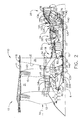
- FIG. 2 Illustrated schematically in FIG. 2 is an alternative turbofan gas turbine engine 10 configuration having a two stage high pressure turbine 324 having two stages of high pressure turbine blades 326 and a row of high pressure turbine vanes 328 as opposed to the turbofan gas turbine engine 10 illustrated in FIGS. 1 and 3 in which the HPT 24 is a single stage high pressure turbine with a single stage of HPT blades 326.
- the fan diameter D of all the engines 10 in the family would be substantially the same.
- At least two different engine models in the family would have either the one stage high pressure turbine 24 or the two stage high pressure turbine 324 of the core engine 25.
- the high pressure compressor 18 of turbofan gas turbine engine 10 of the present invention is operable and designed to operate with a relatively high compressor pressure ratio in a range of about 15-30 and an overall pressure ratio in a range of about 40-65.
- the compressor pressure ratio is a measure in the rise of pressure across just the high pressure compressor 18.
- the overall pressure ratio is a measure in the rise of pressure across the fan all the way through the high pressure compressor 18, i.e., it is a ratio of pressure exiting the high pressure compressor divided by pressure of ambient air 14 entering the fan section 12.
- the high pressure compressor 18 is illustrated having six high pressure stages 48 and three variable vane stages 50 for the first four of the high pressure stages 48. Less than four variable vane stages 50 may be used.
- the high pressure compressor 18 has a relatively small number of the high pressure stages 48 and the invention contemplates using between 6-8 of the high pressure stages and about four of the variable vane stages 50 or less. This makes for a short engine while still having a high overall pressure ratio in a range of 40-65.
- the engine has a design bypass ratio in a range of 5-15 and a design fan pressure ratio in a range of 1.4 - 2.5.
- the counter rotating first and second fan blade rows 13 and 15 are designed to operate with tip speeds that, for the two blade rows, sum to a range of about 1000 to 2500 ft/sec which allows the use of light weight composite fan blades.
- Light weight, uncooled, high temperature capability, counter rotating ceramic matrix composite (CMC) airfoils may be used in the counter rotating low pressure turbine 26.
- CMC counter rotating ceramic matrix composite
- a tip radius RT is Illustrated in FIG. 1, as measured from the engine centerline. 8 to a fan blade tip 230 of the first fan blade row 13 and a hub radius RH as measured from the engine centerline 8 to a rotor hub 234 of the low pressure inner rotor 200 at an entrance 235 to the inlet duct 19 to the high pressure compressor 18 of the core engine 25.
- the engine 10 of the present invention may be designed with a small fan inlet hub to tip radius ratio (RH/RT) in a range between .20 and .35. For a given set of fan inlet and inlet duct annulus areas a low fan inlet hub to tip radius ratio allows a smaller fan diameter when compared to a larger ratio.
- fan inlet hub to tip radius ratio levels are constrained by the ability to design a disk to support the rotating fan blades.
- the fan blades in the exemplary embodiment illustrated herein are made of lightweight composite materials or aluminum and rotor fan tip speeds are designed so that a fan disk 240 can be designed for the fan inlet hub to tip radius ratio to be as low as .20.
- the low fan inlet hub to tip radius ratio allows low slopes and short lengths of the core engine transition duct 242 between the fan section 12 and the high pressure compressor 18 and of the inter-turbine transition duct 114 between the HPT 24 and the LPT 26.
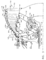
- Oil lubrication and scavenging of oil for the differential bearing 144 is accomplished by routing oil through supply and return orifices 220 and 222, respectively, at low stress location on the aft low pressure outer conical shaft extension 142 as illustrated in FIGS. 1, 3, and 4. This feature helps strengthen the rotors and allow the use of only two bearing support frames, the fan and inter-turbine frames, for the 3 spool design with counter rotating low pressure turbines and rotors.
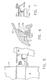
- FIG. 5 Illustrated in FIG. 5 is a first brush seal 223 disposed in sealing arrangement between the second fan 6 and the fan frame 34. Illustrated in FIG. 6 is a second brush seal 224 disposed in sealing arrangement between forward ends 226 of the low pressure turbine casing 54 and the outer drum rotor 136. Illustrated in FIG. 7 is a third brush seal 225 disposed in sealing arrangement between an aft end 228 of the low pressure turbine casing 54 and the final stage 139 of the low pressure turbine blade rows 138 which is bolted to the outer drum rotor 136.
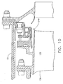
- non contacting seals such as aspirating seals or face seals in some or all of the above locations.
- Illustrated in FIG. 8 is a first non contacting seal 244 disposed in sealing arrangement between the second fan 6 and the fan frame 34.
- Illustrated in FIG. 9 is a second non contacting seal 246 disposed in sealing arrangement between forward ends 226 of the low pressure turbine casing 54 and the outer drum rotor 136.
- Illustrated in FIG. 10 is a third non contacting seal 248 disposed in sealing arrangement between an aft end 228 of the low pressure turbine casing 54 and the final stage 139 of the low pressure turbine blade rows 138 which is bolted to the outer drum rotor 136.
- the seals may be a combination of brush seals and non contacting seals.
Landscapes
- Engineering & Computer Science (AREA)
- Mechanical Engineering (AREA)
- General Engineering & Computer Science (AREA)
- Chemical & Material Sciences (AREA)
- Combustion & Propulsion (AREA)
- Structures Of Non-Positive Displacement Pumps (AREA)
- Turbine Rotor Nozzle Sealing (AREA)
Claims (10)
- Flugzeuggasturbinentriebwerksanordnung, die aufweist:einen Hochdruckrotor (33), der eine Hochdruckturbine (24) enthält;eine Niederdruckturbine (26), die einen inneren und einen äußeren Niederdruckrotor (200, 202) enthält, die gegenläufig rotieren und hinter dem Hochdruckrotor (33) angeordnet sind;einen Zwischenturbinenrahmen (60), der axial zwischen der Hoch- und der Niederdruckturbine (24, 26) angeordnet ist;wobei der innere und der äußere Niederdruckrotor (200, 202) eine innere bzw. eine äußere Niederdruckwelle (130, 140) aufweisen, die wenigstens teilweise koaxial mit dem Hochdruckrotor (33) und radial innerhalb von diesem drehbar angeordnet sind;ein vorderes und ein hinteres Sumpfelement (104, 106) mit einer vorderen bzw. hinteren zentralen Bohrung (84, 85), wobei das vordere und das hintere Sumpfelement (104, 106) mit einem vorderen bzw. hinteren Abschnitt (108, 110) des Zwischenturbinenrahmens (60), die axial beabstandet sind, durch eine vordere bzw. hintere Lagerträgerstruktur (96, 97) fest verbunden sind, wobei der innere und der äußere Niederdruckrotor (200, 202) durch ein hinterstes Niederdruckrotortraglager (76) drehbar gehaltert sind, das in der hinteren zentralen Bohrung (85) des hinteren Sumpfelementes (106) angebracht ist, wobei der Hochdruckrotor (33) hinten durch ein fünftes Lager (94) drehbar radial gehaltert ist, das in der vorderen Lagerträgerstruktur (96) angebracht ist,wobei der Zwischenturbinenrahmen (60) einen ersten tragenden Ring (86), einen zweiten tragenden Ring (88), der zu dem ersten tragenden Ring (86) koaxial und radial beabstandet innerhalb desselben um eine Zentrallinie (8) herum angeordnet ist, und mehrere in Umfangsrichtung voneinander beabstandete, sich zwischen dem ersten und dem zweiten tragenden Ring (86, 88) radial erstreckende Streben (90) aufweist,gekennzeichnet durcheine Rahmenverbindungseinrichtung (120), die an dem ersten tragenden Ring (86) angeordnet ist, um das Triebwerk mit einem Flugzeug zu verbinden.
- Anordnung nach Anspruch 1, die weiterhin eine Auslassleitschaufelanordnung (150) enthält, die eine Reihe von Auslassleitschaufeln (152) trägt, die sich zwischen einem Niederdruckturbinengehäuse (54), das strukturell mit dem Zwischenturbinenrahmen (60) verbunden ist, und einer ringförmigen Kastenstruktur (154) radial erstrecken.
- Anordnung nach Anspruch 2, die weiterhin aufweist:einen drehbaren ringförmigen äußeren Trommelrotor (136), der durch die innere Niederdruckwelle (130) antreibend mit einer ersten Reihe (13) von Bläserschaufeln und einem ersten Booster (16) verbunden ist,einen drehbaren ringförmigen inneren Trommelrotor (146), der durch die äußere Niederdruckwelle (140) antreibend mit einer zweiten Reihe (15) von Bläserschaufeln und einem zweiten Booster (17) verbunden ist,wobei der erste und der zweite Booster (16, 17) axial zwischen der ersten und der zweiten Reihe (13, 15) von Bläserschaufeln angeordnet sind,einen Nebenstromkanal (21), der durch ein Bläsergehäuse (11) und eine ringförmige radial innere Nebenstromkanalwand (9) radial begrenzt ist, die den ersten und den zweiten Booster (16, 17) umgibt,wobei ein radial äußerer Abschnitt (23) der zweiten Reihe (15) von Bläserschaufeln radial innerhalb des Nebenstromkanals (21) angeordnet ist.
- Anordnung nach Anspruch 3, bei der die Rahmenverbindendungseinrichtung wenigstens eine U-förmige Klammer (122) aufweist.
- Anordnung nach Anspruch 4, die weiterhin eine Deckplatte (156) aufweist, die mit der ringförmigen Kastenstruktur (154) verschraubt ist.
- Anordnung nach Anspruch 3, die weiterhin aufweist:ein Nabe/Spitze-Radiusverhältnis (RH/RT) des Bläsereinlasses in einem Bereich zwischen 0,20 und 0,35 ,einen Hochdruckverdichter (18) des Hochdruckrotors (33), der über eine Hochdruckwelle (27) mit der Hochdruckturbine (24) angetrieben verbunden ist,wobei der Hochdruckverdichter (18) ein Gesamtbetriebsdruckverhältnis in einem Bereich von etwa 40 bis 65 aufweist, undein Nebenstromverhältnis in einem Bereich von 5 bis 15, ein betriebliches Bläserdruckverhältnis in einem Bereich von 1,4 bis 2,5 und eine Summe der betrieblichen Bläserspitzengeschwindigkeiten der ersten und zweiten Reihe (13, 15) von Bläserschaufeln in einem Bereich von 1000 bis 2500 Fuß pro Sekunde.
- Anordnung nach Anspruch 3, die weiterhin aufweist:eine erste Dichtung (223) in abdichtender Anordnung zwischen dem zweiten Bläser (6) und dem Bläserrahmen (34),eine zweite Dichtung (224) in abdichtender Anordnung zwischen vorderen Enden (226) des Niederdruckturbinengehäuses (54) und dem äußeren Trommelrotor (136) undeine dritte Dichtung (225) in abdichtender Anordnung zwischen dem Niederdruckturbinengehäuse (54) und einer letzten Stufe (139) der Niederdruckturbinenschaufelreihen (138), die mit einem hinteren Ende des äußeren Trommelrotors (136) verschraubt ist.
- Anordnung nach Anspruch 7, bei der die Dichtungen (223, 224, 225) Bürstendichtungen sind.
- Anordnung nach Anspruch 7, bei der die Dichtungen (244, 246, 248) berührungslose Dichtungen sind.
- Anordnung nach Anspruch 7, bei der die Dichtungen (223, 224, 225) Bürstendichtungen oder berührungslose Dichtungen sind.
Applications Claiming Priority (2)
| Application Number | Priority Date | Filing Date | Title |
|---|---|---|---|
| US87681 | 2002-03-01 | ||
| US10/087,681 US6619030B1 (en) | 2002-03-01 | 2002-03-01 | Aircraft engine with inter-turbine engine frame supported counter rotating low pressure turbine rotors |
Publications (3)
| Publication Number | Publication Date |
|---|---|
| EP1340902A2 EP1340902A2 (de) | 2003-09-03 |
| EP1340902A3 EP1340902A3 (de) | 2004-12-22 |
| EP1340902B1 true EP1340902B1 (de) | 2007-06-13 |
Family
ID=27733445
Family Applications (1)
| Application Number | Title | Priority Date | Filing Date |
|---|---|---|---|
| EP02258821A Expired - Lifetime EP1340902B1 (de) | 2002-03-01 | 2002-12-23 | Gasturbine mit gegenläufigen Niederdruckrotoren |
Country Status (6)
| Country | Link |
|---|---|
| US (1) | US6619030B1 (de) |
| EP (1) | EP1340902B1 (de) |
| JP (1) | JP4204310B2 (de) |
| CA (1) | CA2414992C (de) |
| DE (1) | DE60220636T2 (de) |
| RU (1) | RU2295046C2 (de) |
Cited By (1)
| Publication number | Priority date | Publication date | Assignee | Title |
|---|---|---|---|---|
| US8061968B2 (en) | 2004-12-01 | 2011-11-22 | United Technologies Corporation | Counter-rotating compressor case and assembly method for tip turbine engine |
Families Citing this family (317)
| Publication number | Priority date | Publication date | Assignee | Title |
|---|---|---|---|---|
| US6684626B1 (en) * | 2002-07-30 | 2004-02-03 | General Electric Company | Aircraft gas turbine engine with control vanes for counter rotating low pressure turbines |
| US6763652B2 (en) * | 2002-09-24 | 2004-07-20 | General Electric Company | Variable torque split aircraft gas turbine engine counter rotating low pressure turbines |
| US6763653B2 (en) * | 2002-09-24 | 2004-07-20 | General Electric Company | Counter rotating fan aircraft gas turbine engine with aft booster |
| US7048496B2 (en) * | 2002-10-31 | 2006-05-23 | General Electric Company | Turbine cooling, purge, and sealing system |
| FR2866069A1 (fr) * | 2004-02-06 | 2005-08-12 | Snecma Moteurs | Turboreacteur a soufflante solidaire d'un arbre d'entrainement supporte par un premier et un deuxieme paliers |
| FR2866068B1 (fr) * | 2004-02-06 | 2006-07-07 | Snecma Moteurs | Turboreacteur a soufflante solidaire d'un arbre d'entrainement supporte par un premier et un deuxieme paliers |
| FR2866073B1 (fr) * | 2004-02-11 | 2006-07-28 | Snecma Moteurs | Turboreacteur ayant deux soufflantes contrarotatives solidaires d'un compresseur a basse pression contrarotatif |
| GB0406174D0 (en) * | 2004-03-19 | 2004-04-21 | Rolls Royce Plc | Turbine engine arrangement |
| US7093418B2 (en) * | 2004-04-21 | 2006-08-22 | Honeywell International, Inc. | Gas turbine engine including a low pressure sump seal buffer source and thermally isolated sump |
| US7185484B2 (en) * | 2004-08-11 | 2007-03-06 | General Electric Company | Methods and apparatus for assembling a gas turbine engine |
| ITMI20041778A1 (it) * | 2004-09-17 | 2004-12-17 | Nuovo Pignone Spa | Fondo bombato di tenuta per una turbina bialbero |
| JP5124276B2 (ja) * | 2004-10-07 | 2013-01-23 | ボルボ エアロ コーポレイション | ガスタービン中間構造および該中間構造を含むガスタービンエンジン |
| US7269938B2 (en) * | 2004-10-29 | 2007-09-18 | General Electric Company | Counter-rotating gas turbine engine and method of assembling same |
| US7334392B2 (en) * | 2004-10-29 | 2008-02-26 | General Electric Company | Counter-rotating gas turbine engine and method of assembling same |
| US7195446B2 (en) * | 2004-10-29 | 2007-03-27 | General Electric Company | Counter-rotating turbine engine and method of assembling same |
| US7195447B2 (en) * | 2004-10-29 | 2007-03-27 | General Electric Company | Gas turbine engine and method of assembling same |
| US7186073B2 (en) * | 2004-10-29 | 2007-03-06 | General Electric Company | Counter-rotating gas turbine engine and method of assembling same |
| US7290386B2 (en) * | 2004-10-29 | 2007-11-06 | General Electric Company | Counter-rotating gas turbine engine and method of assembling same |
| US7296398B2 (en) * | 2004-10-29 | 2007-11-20 | General Electric Company | Counter-rotating turbine engine and method of assembling same |
| US7334981B2 (en) * | 2004-10-29 | 2008-02-26 | General Electric Company | Counter-rotating gas turbine engine and method of assembling same |
| US7409819B2 (en) * | 2004-10-29 | 2008-08-12 | General Electric Company | Gas turbine engine and method of assembling same |
| US7458202B2 (en) * | 2004-10-29 | 2008-12-02 | General Electric Company | Lubrication system for a counter-rotating turbine engine and method of assembling same |
| WO2006060013A1 (en) * | 2004-12-01 | 2006-06-08 | United Technologies Corporation | Seal assembly for a fan rotor of a tip turbine engine |
| WO2006059972A1 (en) * | 2004-12-01 | 2006-06-08 | United Technologies Corporation | Compressor variable stage remote actuation for turbine engine |
| US8365511B2 (en) * | 2004-12-01 | 2013-02-05 | United Technologies Corporation | Tip turbine engine integral case, vane, mount and mixer |
| WO2006059996A1 (en) * | 2004-12-01 | 2006-06-08 | United Technologies Corporation | Balanced turbine rotor fan blade for a tip turbine engine |
| US7874163B2 (en) * | 2004-12-01 | 2011-01-25 | United Technologies Corporation | Starter generator system for a tip turbine engine |
| EP1825128B1 (de) * | 2004-12-01 | 2011-03-02 | United Technologies Corporation | Regenerative Kühlung einer Leit- und Laufschaufel für ein Tipturbinentriebwerk |
| US8083030B2 (en) * | 2004-12-01 | 2011-12-27 | United Technologies Corporation | Gearbox lubrication supply system for a tip engine |
| US8152469B2 (en) * | 2004-12-01 | 2012-04-10 | United Technologies Corporation | Annular turbine ring rotor |
| EP1834067B1 (de) * | 2004-12-01 | 2008-11-26 | United Technologies Corporation | Gebläseschaufelanordnung für ein tip-turbinentriebwerk und montageverfahren |
| WO2006060001A1 (en) * | 2004-12-01 | 2006-06-08 | United Technologies Corporation | Fan rotor assembly for a tip turbine engine |
| US8033092B2 (en) * | 2004-12-01 | 2011-10-11 | United Technologies Corporation | Tip turbine engine integral fan, combustor, and turbine case |
| EP1828567B1 (de) | 2004-12-01 | 2011-10-12 | United Technologies Corporation | Diffusor-ansaugung für einen spitzenturbinenmotor |
| EP1828683B1 (de) | 2004-12-01 | 2013-04-10 | United Technologies Corporation | Brennkammer für turbinenmotor |
| WO2006060011A1 (en) * | 2004-12-01 | 2006-06-08 | United Technologies Corporation | Tip turbine engine comprising a nonrotable compartment |
| WO2006059994A1 (en) * | 2004-12-01 | 2006-06-08 | United Technologies Corporation | Seal assembly for a fan-turbine rotor of a tip turbine engine |
| WO2006060000A1 (en) | 2004-12-01 | 2006-06-08 | United Technologies Corporation | Variable fan inlet guide vane assembly, turbine engine with such an assembly and corresponding controlling method |
| EP1825117B1 (de) * | 2004-12-01 | 2012-06-13 | United Technologies Corporation | Turbinentriebwerk mit von einem differentialgetriebe angetriebenem fan und verdichter |
| US8641367B2 (en) | 2004-12-01 | 2014-02-04 | United Technologies Corporation | Plurality of individually controlled inlet guide vanes in a turbofan engine and corresponding controlling method |
| EP1825177B1 (de) | 2004-12-01 | 2012-01-25 | United Technologies Corporation | Aufblasbares ablassventil für eine turbomaschine und verfahren zur steuerung von ablassluft |
| US7845157B2 (en) | 2004-12-01 | 2010-12-07 | United Technologies Corporation | Axial compressor for tip turbine engine |
| DE602004028528D1 (de) * | 2004-12-01 | 2010-09-16 | United Technologies Corp | Tip-Turbinentriebwerk mit mehreren Gebläse- und Turbinenstufen |
| WO2006110123A2 (en) * | 2004-12-01 | 2006-10-19 | United Technologies Corporation | Vectoring transition duct for turbine engine |
| US9003759B2 (en) | 2004-12-01 | 2015-04-14 | United Technologies Corporation | Particle separator for tip turbine engine |
| US20090169385A1 (en) * | 2004-12-01 | 2009-07-02 | Suciu Gabriel L | Fan-turbine rotor assembly with integral inducer section for a tip turbine engine |
| DE602004028297D1 (de) * | 2004-12-01 | 2010-09-02 | United Technologies Corp | Umfangsbrennkammer für spitzenturbinenmotor |
| EP1831520B1 (de) * | 2004-12-01 | 2009-02-25 | United Technologies Corporation | Tip-turbinentriebwerk und entsprechendes betriebsverfahren |
| US7887296B2 (en) * | 2004-12-01 | 2011-02-15 | United Technologies Corporation | Fan blade with integral diffuser section and tip turbine blade section for a tip turbine engine |
| US7882695B2 (en) | 2004-12-01 | 2011-02-08 | United Technologies Corporation | Turbine blow down starter for turbine engine |
| EP1828546B1 (de) * | 2004-12-01 | 2009-10-21 | United Technologies Corporation | Gestapelte ringförmige bauteile für turbinenmotoren |
| WO2006059978A1 (en) * | 2004-12-01 | 2006-06-08 | United Technologies Corporation | Cantilevered tip turbine engine |
| WO2006060009A1 (en) * | 2004-12-01 | 2006-06-08 | United Technologies Corporation | Turbine blade engine comprising turbine clusters and radial attachment lock arrangement therefor |
| EP1825113B1 (de) | 2004-12-01 | 2012-10-24 | United Technologies Corporation | Gegenläufiges getriebe für ein tip-turbinen-triebwerk |
| US7976273B2 (en) * | 2004-12-01 | 2011-07-12 | United Technologies Corporation | Tip turbine engine support structure |
| EP1834071B1 (de) * | 2004-12-01 | 2013-03-13 | United Technologies Corporation | Einlaufteil für einen lüfterflügel eines spitzenturbinenmotors |
| US9845727B2 (en) * | 2004-12-01 | 2017-12-19 | United Technologies Corporation | Tip turbine engine composite tailcone |
| US7631480B2 (en) * | 2004-12-01 | 2009-12-15 | United Technologies Corporation | Modular tip turbine engine |
| DE602004029950D1 (de) * | 2004-12-01 | 2010-12-16 | United Technologies Corp | Enggekoppelte getriebeanordnung für einen spitzenturbinenmotor |
| US20090148273A1 (en) * | 2004-12-01 | 2009-06-11 | Suciu Gabriel L | Compressor inlet guide vane for tip turbine engine and corresponding control method |
| EP1828573B1 (de) * | 2004-12-01 | 2010-06-16 | United Technologies Corporation | Hydraulische dichtung für ein getriebe eines spitzenturbinenmotors |
| WO2006059986A1 (en) | 2004-12-01 | 2006-06-08 | United Technologies Corporation | Tip turbine engine and operating method with reverse core airflow |
| US7980054B2 (en) * | 2004-12-01 | 2011-07-19 | United Technologies Corporation | Ejector cooling of outer case for tip turbine engine |
| US9109537B2 (en) * | 2004-12-04 | 2015-08-18 | United Technologies Corporation | Tip turbine single plane mount |
| US7334982B2 (en) * | 2005-05-06 | 2008-02-26 | General Electric Company | Apparatus for scavenging lubricating oil |
| US7594388B2 (en) * | 2005-06-06 | 2009-09-29 | General Electric Company | Counterrotating turbofan engine |
| US7510371B2 (en) * | 2005-06-06 | 2009-03-31 | General Electric Company | Forward tilted turbine nozzle |
| US7513102B2 (en) * | 2005-06-06 | 2009-04-07 | General Electric Company | Integrated counterrotating turbofan |
| US20070028595A1 (en) * | 2005-07-25 | 2007-02-08 | Mongia Hukam C | High pressure gas turbine engine having reduced emissions |
| US20070079507A1 (en) * | 2005-10-12 | 2007-04-12 | Kenny Cheng | Blade shroud repair |
| US7490460B2 (en) * | 2005-10-19 | 2009-02-17 | General Electric Company | Gas turbine engine assembly and methods of assembling same |
| US7603844B2 (en) * | 2005-10-19 | 2009-10-20 | General Electric Company | Gas turbine engine assembly and methods of assembling same |
| US7685808B2 (en) | 2005-10-19 | 2010-03-30 | General Electric Company | Gas turbine engine assembly and methods of assembling same |
| US7493753B2 (en) * | 2005-10-19 | 2009-02-24 | General Electric Company | Gas turbine engine assembly and methods of assembling same |
| US7726113B2 (en) * | 2005-10-19 | 2010-06-01 | General Electric Company | Gas turbine engine assembly and methods of assembling same |
| US7490461B2 (en) * | 2005-10-19 | 2009-02-17 | General Electric Company | Gas turbine engine assembly and methods of assembling same |
| US7752836B2 (en) * | 2005-10-19 | 2010-07-13 | General Electric Company | Gas turbine assembly and methods of assembling same |
| US7526913B2 (en) * | 2005-10-19 | 2009-05-05 | General Electric Company | Gas turbine engine assembly and methods of assembling same |
| US7513103B2 (en) * | 2005-10-19 | 2009-04-07 | General Electric Company | Gas turbine engine assembly and methods of assembling same |
| US7493754B2 (en) * | 2005-10-19 | 2009-02-24 | General Electric Company | Gas turbine engine assembly and methods of assembling same |
| US7610763B2 (en) | 2006-05-09 | 2009-11-03 | United Technologies Corporation | Tailorable design configuration topologies for aircraft engine mid-turbine frames |
| US7594405B2 (en) * | 2006-07-27 | 2009-09-29 | United Technologies Corporation | Catenary mid-turbine frame design |
| US7694505B2 (en) * | 2006-07-31 | 2010-04-13 | General Electric Company | Gas turbine engine assembly and method of assembling same |
| US7870719B2 (en) * | 2006-10-13 | 2011-01-18 | General Electric Company | Plasma enhanced rapidly expanded gas turbine engine transition duct |
| US20080095616A1 (en) * | 2006-10-20 | 2008-04-24 | Ioannis Alvanos | Fluid brush seal with segment seal land |
| US7766599B2 (en) | 2006-10-31 | 2010-08-03 | General Electric Company | Plasma lifted boundary layer gas turbine engine vane |
| US7926259B2 (en) * | 2006-10-31 | 2011-04-19 | General Electric Company | Turbofan engine assembly and method of assembling same |
| US7841165B2 (en) * | 2006-10-31 | 2010-11-30 | General Electric Company | Gas turbine engine assembly and methods of assembling same |
| FR2908452A1 (fr) * | 2006-11-15 | 2008-05-16 | Snecma Sa | Dispositif de fixation de stator de turbine libre par double centrage. |
| US7882693B2 (en) * | 2006-11-29 | 2011-02-08 | General Electric Company | Turbofan engine assembly and method of assembling same |
| US7695241B2 (en) * | 2006-11-30 | 2010-04-13 | General Electric Company | Downstream plasma shielded film cooling |
| US7588413B2 (en) * | 2006-11-30 | 2009-09-15 | General Electric Company | Upstream plasma shielded film cooling |
| US7797946B2 (en) * | 2006-12-06 | 2010-09-21 | United Technologies Corporation | Double U design for mid-turbine frame struts |
| US7765789B2 (en) * | 2006-12-15 | 2010-08-03 | General Electric Company | Apparatus and method for assembling gas turbine engines |
| US7736123B2 (en) * | 2006-12-15 | 2010-06-15 | General Electric Company | Plasma induced virtual turbine airfoil trailing edge extension |
| US7628585B2 (en) * | 2006-12-15 | 2009-12-08 | General Electric Company | Airfoil leading edge end wall vortex reducing plasma |
| US7926290B2 (en) * | 2006-12-18 | 2011-04-19 | General Electric Company | Turbine engine with modulated flow fan and method of operation |
| US7716914B2 (en) * | 2006-12-21 | 2010-05-18 | General Electric Company | Turbofan engine assembly and method of assembling same |
| FR2912181B1 (fr) * | 2007-02-07 | 2009-04-24 | Snecma Sa | Turbine a gaz a turbines hp et bp contra-rotatives |
| US8001787B2 (en) * | 2007-02-27 | 2011-08-23 | Siemens Energy, Inc. | Transition support system for combustion transition ducts for turbine engines |
| US8038388B2 (en) * | 2007-03-05 | 2011-10-18 | United Technologies Corporation | Abradable component for a gas turbine engine |
| US8967945B2 (en) | 2007-05-22 | 2015-03-03 | United Technologies Corporation | Individual inlet guide vane control for tip turbine engine |
| US20150377123A1 (en) | 2007-08-01 | 2015-12-31 | United Technologies Corporation | Turbine section of high bypass turbofan |
| US11149650B2 (en) | 2007-08-01 | 2021-10-19 | Raytheon Technologies Corporation | Turbine section of high bypass turbofan |
| US11486311B2 (en) | 2007-08-01 | 2022-11-01 | Raytheon Technologies Corporation | Turbine section of high bypass turbofan |
| US11242805B2 (en) * | 2007-08-01 | 2022-02-08 | Raytheon Technologies Corporation | Turbine section of high bypass turbofan |
| US11346289B2 (en) | 2007-08-01 | 2022-05-31 | Raytheon Technologies Corporation | Turbine section of high bypass turbofan |
| US8844265B2 (en) * | 2007-08-01 | 2014-09-30 | United Technologies Corporation | Turbine section of high bypass turbofan |
| US9701415B2 (en) | 2007-08-23 | 2017-07-11 | United Technologies Corporation | Gas turbine engine with axial movable fan variable area nozzle |
| US9494084B2 (en) | 2007-08-23 | 2016-11-15 | United Technologies Corporation | Gas turbine engine with fan variable area nozzle for low fan pressure ratio |
| US10167813B2 (en) | 2007-08-23 | 2019-01-01 | United Technologies Corporation | Gas turbine engine with fan variable area nozzle to reduce fan instability |
| US20180230912A1 (en) * | 2007-09-21 | 2018-08-16 | United Technologies Corporation | Gas turbine engine compressor arrangement |
| US20140157754A1 (en) * | 2007-09-21 | 2014-06-12 | United Technologies Corporation | Gas turbine engine compressor arrangement |
| FR2921973B1 (fr) * | 2007-10-04 | 2011-04-29 | Snecma | Carter intermediaire de turboreacteur et turboreacteur |
| US8590286B2 (en) * | 2007-12-05 | 2013-11-26 | United Technologies Corp. | Gas turbine engine systems involving tip fans |
| US8402742B2 (en) | 2007-12-05 | 2013-03-26 | United Technologies Corporation | Gas turbine engine systems involving tip fans |
| FR2926337B1 (fr) * | 2008-01-14 | 2013-12-06 | Snecma | Aube directrice de sortie pour un turboreacteur d'avion et turboreacteur comportant cette aube |
| US8292570B2 (en) * | 2008-01-25 | 2012-10-23 | United Technologies Corporation | Low pressure turbine with counter-rotating drives for single spool |
| FR2927366B1 (fr) * | 2008-02-13 | 2013-07-05 | Snecma | Dispositif de recuperation d'huile. |
| US8534074B2 (en) * | 2008-05-13 | 2013-09-17 | Rolls-Royce Corporation | Dual clutch arrangement and method |
| US20140174056A1 (en) * | 2008-06-02 | 2014-06-26 | United Technologies Corporation | Gas turbine engine with low stage count low pressure turbine |
| US8128021B2 (en) | 2008-06-02 | 2012-03-06 | United Technologies Corporation | Engine mount system for a turbofan gas turbine engine |
| US8800914B2 (en) | 2008-06-02 | 2014-08-12 | United Technologies Corporation | Gas turbine engine with low stage count low pressure turbine |
| US8807477B2 (en) | 2008-06-02 | 2014-08-19 | United Technologies Corporation | Gas turbine engine compressor arrangement |
| US20100005810A1 (en) * | 2008-07-11 | 2010-01-14 | Rob Jarrell | Power transmission among shafts in a turbine engine |
| US8113768B2 (en) * | 2008-07-23 | 2012-02-14 | United Technologies Corporation | Actuated variable geometry mid-turbine frame design |
| US8061980B2 (en) * | 2008-08-18 | 2011-11-22 | United Technologies Corporation | Separation-resistant inlet duct for mid-turbine frames |
| US8480527B2 (en) * | 2008-08-27 | 2013-07-09 | Rolls-Royce Corporation | Gearing arrangement |
| US8166748B2 (en) * | 2008-11-21 | 2012-05-01 | General Electric Company | Gas turbine engine booster having rotatable radially inwardly extending blades and non-rotatable vanes |
| US8011877B2 (en) * | 2008-11-24 | 2011-09-06 | General Electric Company | Fiber composite reinforced aircraft gas turbine engine drums with radially inwardly extending blades |
| US8099962B2 (en) * | 2008-11-28 | 2012-01-24 | Pratt & Whitney Canada Corp. | Mid turbine frame system and radial locator for radially centering a bearing for gas turbine engine |
| US8347635B2 (en) * | 2008-11-28 | 2013-01-08 | Pratt & Whitey Canada Corp. | Locking apparatus for a radial locator for gas turbine engine mid turbine frame |
| US20100132377A1 (en) * | 2008-11-28 | 2010-06-03 | Pratt & Whitney Canada Corp. | Fabricated itd-strut and vane ring for gas turbine engine |
| US8091371B2 (en) * | 2008-11-28 | 2012-01-10 | Pratt & Whitney Canada Corp. | Mid turbine frame for gas turbine engine |
| US20100132371A1 (en) * | 2008-11-28 | 2010-06-03 | Pratt & Whitney Canada Corp. | Mid turbine frame system for gas turbine engine |
| US8245518B2 (en) * | 2008-11-28 | 2012-08-21 | Pratt & Whitney Canada Corp. | Mid turbine frame system for gas turbine engine |
| US8347500B2 (en) * | 2008-11-28 | 2013-01-08 | Pratt & Whitney Canada Corp. | Method of assembly and disassembly of a gas turbine mid turbine frame |
| US8061969B2 (en) * | 2008-11-28 | 2011-11-22 | Pratt & Whitney Canada Corp. | Mid turbine frame system for gas turbine engine |
| US8075438B2 (en) * | 2008-12-11 | 2011-12-13 | Rolls-Royce Corporation | Apparatus and method for transmitting a rotary input into counter-rotating outputs |
| US8021267B2 (en) * | 2008-12-11 | 2011-09-20 | Rolls-Royce Corporation | Coupling assembly |
| FR2942976B1 (fr) * | 2009-03-13 | 2012-12-14 | Bernard Etcheparre | Dispositif de projection de fluide par effet de souffle d'air |
| FR2944558B1 (fr) * | 2009-04-17 | 2014-05-02 | Snecma | Moteur a turbine a gaz double corps pourvu d'un palier de turbine bp supplementaire. |
| US8567202B2 (en) * | 2009-05-15 | 2013-10-29 | Pratt & Whitney Canada Corp. | Support links with lockable adjustment feature |
| US8979491B2 (en) | 2009-05-15 | 2015-03-17 | Pratt & Whitney Canada Corp. | Turbofan mounting arrangement |
| US8313293B2 (en) * | 2009-05-15 | 2012-11-20 | Pratt & Whitney Canada Corp. | Turbofan mounting system |
| US20110167784A1 (en) * | 2009-09-25 | 2011-07-14 | James Edward Johnson | Method of operating a convertible fan engine |
| US20110167792A1 (en) * | 2009-09-25 | 2011-07-14 | James Edward Johnson | Adaptive engine |
| US9284887B2 (en) | 2009-12-31 | 2016-03-15 | Rolls-Royce North American Technologies, Inc. | Gas turbine engine and frame |
| US8997500B2 (en) | 2010-02-19 | 2015-04-07 | United Technologies Corporation | Gas turbine engine oil buffering |
| US8845277B2 (en) | 2010-05-24 | 2014-09-30 | United Technologies Corporation | Geared turbofan engine with integral gear and bearing supports |
| EP2392785B1 (de) * | 2010-06-07 | 2016-04-06 | Airbus Operations GmbH | Abgasnachbehandlung in einer Gasturbinenanlage |
| FR2968062B1 (fr) * | 2010-11-26 | 2012-11-16 | Snecma | Dispositif d'evacuation d'huile et turbomachine comprenant un tel dispositif |
| EP2466074A1 (de) | 2010-12-15 | 2012-06-20 | MTU Aero Engines GmbH | Gasturbinentriebwerk mit Kolbenringdichtung |
| US8777793B2 (en) | 2011-04-27 | 2014-07-15 | United Technologies Corporation | Fan drive planetary gear system integrated carrier and torque frame |
| US20120301275A1 (en) * | 2011-05-26 | 2012-11-29 | Suciu Gabriel L | Integrated ceramic matrix composite rotor module for a gas turbine engine |
| US9133729B1 (en) * | 2011-06-08 | 2015-09-15 | United Technologies Corporation | Flexible support structure for a geared architecture gas turbine engine |
| US9239012B2 (en) | 2011-06-08 | 2016-01-19 | United Technologies Corporation | Flexible support structure for a geared architecture gas turbine engine |
| US9631558B2 (en) | 2012-01-03 | 2017-04-25 | United Technologies Corporation | Geared architecture for high speed and small volume fan drive turbine |
| US8708274B2 (en) | 2011-09-09 | 2014-04-29 | United Technologies Corporation | Transverse mounted gas turbine engine |
| US9279341B2 (en) | 2011-09-22 | 2016-03-08 | Pratt & Whitney Canada Corp. | Air system architecture for a mid-turbine frame module |
| CN104136721B (zh) * | 2011-12-30 | 2017-05-31 | 联合工艺公司 | 涡轮发动机及其操作方法 |
| US8979484B2 (en) | 2012-01-05 | 2015-03-17 | Pratt & Whitney Canada Corp. | Casing for an aircraft turbofan bypass engine |
| US20130186058A1 (en) * | 2012-01-24 | 2013-07-25 | William G. Sheridan | Geared turbomachine fan and compressor rotation |
| US9316117B2 (en) | 2012-01-30 | 2016-04-19 | United Technologies Corporation | Internally cooled spoke |
| US20130192201A1 (en) * | 2012-01-31 | 2013-08-01 | United Technologies Corporation | Geared turbofan gas turbine engine architecture |
| US9611859B2 (en) | 2012-01-31 | 2017-04-04 | United Technologies Corporation | Gas turbine engine with high speed low pressure turbine section and bearing support features |
| US10400629B2 (en) | 2012-01-31 | 2019-09-03 | United Technologies Corporation | Gas turbine engine shaft bearing configuration |
| US10240526B2 (en) | 2012-01-31 | 2019-03-26 | United Technologies Corporation | Gas turbine engine with high speed low pressure turbine section |
| US9140137B2 (en) | 2012-01-31 | 2015-09-22 | United Technologies Corporation | Gas turbine engine mid turbine frame bearing support |
| US8863491B2 (en) | 2012-01-31 | 2014-10-21 | United Technologies Corporation | Gas turbine engine shaft bearing configuration |
| US20150345426A1 (en) | 2012-01-31 | 2015-12-03 | United Technologies Corporation | Geared turbofan gas turbine engine architecture |
| US8402741B1 (en) | 2012-01-31 | 2013-03-26 | United Technologies Corporation | Gas turbine engine shaft bearing configuration |
| US10287914B2 (en) | 2012-01-31 | 2019-05-14 | United Technologies Corporation | Gas turbine engine with high speed low pressure turbine section and bearing support features |
| US8887487B2 (en) * | 2012-01-31 | 2014-11-18 | United Technologies Corporation | Geared turbofan gas turbine engine architecture |
| US20130192266A1 (en) * | 2012-01-31 | 2013-08-01 | United Technologies Corporation | Geared turbofan gas turbine engine architecture |
| US9222417B2 (en) | 2012-01-31 | 2015-12-29 | United Technologies Corporation | Geared turbofan gas turbine engine architecture |
| US9038366B2 (en) | 2012-01-31 | 2015-05-26 | United Technologies Corporation | LPC flowpath shape with gas turbine engine shaft bearing configuration |
| US10415468B2 (en) * | 2012-01-31 | 2019-09-17 | United Technologies Corporation | Gas turbine engine buffer system |
| US8935913B2 (en) | 2012-01-31 | 2015-01-20 | United Technologies Corporation | Geared turbofan gas turbine engine architecture |
| US20130192258A1 (en) * | 2012-01-31 | 2013-08-01 | United Technologies Corporation | Geared turbofan gas turbine engine architecture |
| US20130192196A1 (en) * | 2012-01-31 | 2013-08-01 | Gabriel L. Suciu | Gas turbine engine with high speed low pressure turbine section |
| US20130192191A1 (en) | 2012-01-31 | 2013-08-01 | Frederick M. Schwarz | Gas turbine engine with high speed low pressure turbine section and bearing support features |
| US10837367B2 (en) * | 2012-02-28 | 2020-11-17 | Raytheon Technologies Corporation | Acoustic treatment in an unducted area of a geared turbomachine |
| US9856745B2 (en) * | 2012-02-28 | 2018-01-02 | United Technologies Corporation | Acoustic treatment in an unducted area of a geared turbomachine |
| US9080512B2 (en) | 2012-02-29 | 2015-07-14 | United Technologies Corporation | Counter-rotating low pressure turbine with gear system mounted to mid turbine frame |
| US9022725B2 (en) | 2012-02-29 | 2015-05-05 | United Technologies Corporation | Counter-rotating low pressure turbine with gear system mounted to turbine exhaust case |
| US9011076B2 (en) | 2012-02-29 | 2015-04-21 | United Technologies Corporation | Counter-rotating low pressure turbine with gear system mounted to turbine exhaust case |
| US9194290B2 (en) | 2012-02-29 | 2015-11-24 | United Technologies Corporation | Counter-rotating low pressure turbine without turbine exhaust case |
| US10138809B2 (en) | 2012-04-02 | 2018-11-27 | United Technologies Corporation | Geared turbofan engine with a high ratio of thrust to turbine volume |
| US10125693B2 (en) | 2012-04-02 | 2018-11-13 | United Technologies Corporation | Geared turbofan engine with power density range |
| US20130269479A1 (en) * | 2012-04-11 | 2013-10-17 | General Electric Company | Gearbox and support apparatus for gearbox carrier |
| US9074485B2 (en) | 2012-04-25 | 2015-07-07 | United Technologies Corporation | Geared turbofan with three turbines all counter-rotating |
| EP3708792A1 (de) * | 2012-04-25 | 2020-09-16 | United Technologies Corporation | Gasturbinenmotor mit schnellem niederdruckturbinenabschnitt und lagerträgerfunktionen |
| US9194296B2 (en) | 2012-05-18 | 2015-11-24 | Pratt & Whitney Canada Corp. | Inner bypass duct wall attachment |
| US8756908B2 (en) | 2012-05-31 | 2014-06-24 | United Technologies Corporation | Fundamental gear system architecture |
| US8833086B2 (en) * | 2012-05-31 | 2014-09-16 | United Technologies Corporation | Lubrication arrangement for a gas turbine engine gear assembly |
| US20150308351A1 (en) | 2012-05-31 | 2015-10-29 | United Technologies Corporation | Fundamental gear system architecture |
| US8572943B1 (en) | 2012-05-31 | 2013-11-05 | United Technologies Corporation | Fundamental gear system architecture |
| US9410427B2 (en) * | 2012-06-05 | 2016-08-09 | United Technologies Corporation | Compressor power and torque transmitting hub |
| US20140010648A1 (en) * | 2012-06-29 | 2014-01-09 | United Technologies Corporation | Sleeve for turbine bearing stack |
| US9410441B2 (en) | 2012-09-13 | 2016-08-09 | Pratt & Whitney Canada Corp. | Turboprop engine with compressor turbine shroud |
| US9790861B2 (en) * | 2012-09-28 | 2017-10-17 | United Technologies Corporation | Gas turbine engine having support structure with swept leading edge |
| US9869191B2 (en) * | 2012-10-09 | 2018-01-16 | United Technologies Corporation | Geared low fan pressure ratio fan exit guide vane stagger angle |
| US20140130479A1 (en) * | 2012-11-14 | 2014-05-15 | United Technologies Corporation | Gas Turbine Engine With Mount for Low Pressure Turbine Section |
| US10378370B2 (en) | 2012-12-29 | 2019-08-13 | United Technologies Corporation | Mechanical linkage for segmented heat shield |
| US10240481B2 (en) | 2012-12-29 | 2019-03-26 | United Technologies Corporation | Angled cut to direct radiative heat load |
| US10294819B2 (en) | 2012-12-29 | 2019-05-21 | United Technologies Corporation | Multi-piece heat shield |
| WO2014105780A1 (en) | 2012-12-29 | 2014-07-03 | United Technologies Corporation | Multi-purpose gas turbine seal support and assembly |
| GB2524211B (en) | 2012-12-29 | 2021-05-26 | United Technologies Corp | Turbine frame assembly and method of designing turbine frame assembly |
| WO2014105599A1 (en) | 2012-12-29 | 2014-07-03 | United Technologies Corporation | Heat shield for cooling a strut |
| US9771818B2 (en) | 2012-12-29 | 2017-09-26 | United Technologies Corporation | Seals for a circumferential stop ring in a turbine exhaust case |
| US9297312B2 (en) | 2012-12-29 | 2016-03-29 | United Technologies Corporation | Circumferentially retained fairing |
| US9347330B2 (en) | 2012-12-29 | 2016-05-24 | United Technologies Corporation | Finger seal |
| WO2014105616A1 (en) | 2012-12-29 | 2014-07-03 | United Technologies Corporation | Turbine exhaust case architecture |
| US9828867B2 (en) | 2012-12-29 | 2017-11-28 | United Technologies Corporation | Bumper for seals in a turbine exhaust case |
| WO2014137444A2 (en) | 2012-12-29 | 2014-09-12 | United Technologies Corporation | Multi-ply finger seal |
| US9850780B2 (en) | 2012-12-29 | 2017-12-26 | United Technologies Corporation | Plate for directing flow and film cooling of components |
| US9541006B2 (en) | 2012-12-29 | 2017-01-10 | United Technologies Corporation | Inter-module flow discourager |
| US9850774B2 (en) | 2012-12-29 | 2017-12-26 | United Technologies Corporation | Flow diverter element and assembly |
| WO2014143329A2 (en) | 2012-12-29 | 2014-09-18 | United Technologies Corporation | Frame junction cooling holes |
| WO2014105803A1 (en) | 2012-12-29 | 2014-07-03 | United Technologies Corporation | Gas turbine seal assembly and seal support |
| US9206742B2 (en) | 2012-12-29 | 2015-12-08 | United Technologies Corporation | Passages to facilitate a secondary flow between components |
| WO2014105577A1 (en) | 2012-12-29 | 2014-07-03 | United Technologies Corporation | Scupper channelling in gas turbine modules |
| WO2014105657A1 (en) | 2012-12-29 | 2014-07-03 | United Technologies Corporation | Mount with deflectable tabs |
| US10472987B2 (en) | 2012-12-29 | 2019-11-12 | United Technologies Corporation | Heat shield for a casing |
| US9562478B2 (en) | 2012-12-29 | 2017-02-07 | United Technologies Corporation | Inter-module finger seal |
| US9631517B2 (en) | 2012-12-29 | 2017-04-25 | United Technologies Corporation | Multi-piece fairing for monolithic turbine exhaust case |
| US10329956B2 (en) | 2012-12-29 | 2019-06-25 | United Technologies Corporation | Multi-function boss for a turbine exhaust case |
| US10094389B2 (en) | 2012-12-29 | 2018-10-09 | United Technologies Corporation | Flow diverter to redirect secondary flow |
| WO2014105800A1 (en) | 2012-12-29 | 2014-07-03 | United Technologies Corporation | Gas turbine seal assembly and seal support |
| US9863261B2 (en) | 2012-12-29 | 2018-01-09 | United Technologies Corporation | Component retention with probe |
| US10060279B2 (en) | 2012-12-29 | 2018-08-28 | United Technologies Corporation | Seal support disk and assembly |
| WO2014105688A1 (en) | 2012-12-31 | 2014-07-03 | United Technologies Corporation | Turbine exhaust case multi-piece frame |
| WO2014105682A1 (en) | 2012-12-31 | 2014-07-03 | United Technologies Corporation | Turbine exhaust case multi-piece frame |
| GB2524443B (en) | 2012-12-31 | 2020-02-12 | United Technologies Corp | Turbine exhaust case multi-piece frame |
| US20140182293A1 (en) * | 2012-12-31 | 2014-07-03 | United Technologies Corporation | Compressor Rotor for Gas Turbine Engine With Deep Blade Groove |
| BR112015017110A2 (pt) * | 2013-01-18 | 2017-07-11 | Gen Electric | motor de turbina a gás |
| US10330011B2 (en) | 2013-03-11 | 2019-06-25 | United Technologies Corporation | Bench aft sub-assembly for turbine exhaust case fairing |
| US9624827B2 (en) | 2013-03-15 | 2017-04-18 | United Technologies Corporation | Thrust efficient turbofan engine |
| US10724479B2 (en) | 2013-03-15 | 2020-07-28 | United Technologies Corporation | Thrust efficient turbofan engine |
| DE102013213517A1 (de) * | 2013-07-10 | 2015-01-15 | Rolls-Royce Deutschland Ltd & Co Kg | Flugtriebwerk |
| US20160201684A1 (en) * | 2013-09-30 | 2016-07-14 | United Technologies Corporation | Compressor area splits for geared turbofan |
| US10502163B2 (en) * | 2013-11-01 | 2019-12-10 | United Technologies Corporation | Geared turbofan arrangement with core split power ratio |
| US9598981B2 (en) * | 2013-11-22 | 2017-03-21 | Siemens Energy, Inc. | Industrial gas turbine exhaust system diffuser inlet lip |
| EP2886802B1 (de) * | 2013-12-20 | 2019-04-10 | Safran Aero Boosters SA | Innenringdichtung der letzten Kompressorstufe eines axialen Turbotriebwerks |
| US9739205B2 (en) | 2013-12-23 | 2017-08-22 | United Technologies Corporation | Geared turbofan with a gearbox upstream of a fan drive turbine |
| US20150240712A1 (en) * | 2014-02-24 | 2015-08-27 | United Technologies Corporation | Mid-turbine duct for geared gas turbine engine |
| US9869190B2 (en) | 2014-05-30 | 2018-01-16 | General Electric Company | Variable-pitch rotor with remote counterweights |
| US11448123B2 (en) * | 2014-06-13 | 2022-09-20 | Raytheon Technologies Corporation | Geared turbofan architecture |
| US10072510B2 (en) | 2014-11-21 | 2018-09-11 | General Electric Company | Variable pitch fan for gas turbine engine and method of assembling the same |
| US20160167798A1 (en) * | 2014-12-12 | 2016-06-16 | General Electric Company | Variable pitch mounting for aircraft gas turbine engine |
| US20160230674A1 (en) * | 2015-02-09 | 2016-08-11 | United Technologies Corporation | Gear reduction for lower thrust geared turbofan |
| CA2934668C (en) * | 2015-07-09 | 2018-11-06 | General Electric Company | Bearing assembly for supporting a rotor shaft of a gas turbine engine |
| US10920612B2 (en) | 2015-07-24 | 2021-02-16 | Pratt & Whitney Canada Corp. | Mid-turbine frame spoke cooling system and method |
| US10443449B2 (en) | 2015-07-24 | 2019-10-15 | Pratt & Whitney Canada Corp. | Spoke mounting arrangement |
| US10247035B2 (en) | 2015-07-24 | 2019-04-02 | Pratt & Whitney Canada Corp. | Spoke locking architecture |
| US10100653B2 (en) | 2015-10-08 | 2018-10-16 | General Electric Company | Variable pitch fan blade retention system |
| US10273812B2 (en) | 2015-12-18 | 2019-04-30 | Pratt & Whitney Canada Corp. | Turbine rotor coolant supply system |
| FR3053728B1 (fr) * | 2016-07-07 | 2022-01-21 | Safran Aircraft Engines | Support de palier en deux pieces |
| US10364748B2 (en) | 2016-08-19 | 2019-07-30 | United Technologies Corporation | Finger seal flow metering |
| US11053797B2 (en) * | 2017-01-23 | 2021-07-06 | General Electric Company | Rotor thrust balanced turbine engine |
| US11111858B2 (en) | 2017-01-27 | 2021-09-07 | General Electric Company | Cool core gas turbine engine |
| US20180216575A1 (en) * | 2017-01-27 | 2018-08-02 | General Electric Company | Cool core gas turbine engine |
| US10371383B2 (en) | 2017-01-27 | 2019-08-06 | General Electric Company | Unitary flow path structure |
| US10378770B2 (en) | 2017-01-27 | 2019-08-13 | General Electric Company | Unitary flow path structure |
| US10393381B2 (en) | 2017-01-27 | 2019-08-27 | General Electric Company | Unitary flow path structure |
| US10253643B2 (en) | 2017-02-07 | 2019-04-09 | General Electric Company | Airfoil fluid curtain to mitigate or prevent flow path leakage |
| US10823114B2 (en) | 2017-02-08 | 2020-11-03 | General Electric Company | Counter rotating turbine with reversing reduction gearbox |
| US10801442B2 (en) | 2017-02-08 | 2020-10-13 | General Electric Company | Counter rotating turbine with reversing reduction gear assembly |
| US10465606B2 (en) | 2017-02-08 | 2019-11-05 | General Electric Company | Counter rotating turbine with reversing reduction gearbox |
| US10876407B2 (en) * | 2017-02-16 | 2020-12-29 | General Electric Company | Thermal structure for outer diameter mounted turbine blades |
| US10385776B2 (en) | 2017-02-23 | 2019-08-20 | General Electric Company | Methods for assembling a unitary flow path structure |
| US10378373B2 (en) | 2017-02-23 | 2019-08-13 | General Electric Company | Flow path assembly with airfoils inserted through flow path boundary |
| US10370990B2 (en) | 2017-02-23 | 2019-08-06 | General Electric Company | Flow path assembly with pin supported nozzle airfoils |
| US10385709B2 (en) | 2017-02-23 | 2019-08-20 | General Electric Company | Methods and features for positioning a flow path assembly within a gas turbine engine |
| US10247019B2 (en) | 2017-02-23 | 2019-04-02 | General Electric Company | Methods and features for positioning a flow path inner boundary within a flow path assembly |
| US10253641B2 (en) | 2017-02-23 | 2019-04-09 | General Electric Company | Methods and assemblies for attaching airfoils within a flow path |
| US10519860B2 (en) * | 2017-03-07 | 2019-12-31 | General Electric Company | Turbine frame and bearing arrangement for three spool engine |
| US10137981B2 (en) * | 2017-03-31 | 2018-11-27 | General Electric Company | Electric propulsion system for an aircraft |
| US10294821B2 (en) | 2017-04-12 | 2019-05-21 | General Electric Company | Interturbine frame for gas turbine engine |
| US10385731B2 (en) | 2017-06-12 | 2019-08-20 | General Electric Company | CTE matching hanger support for CMC structures |
| US10914194B2 (en) | 2017-09-20 | 2021-02-09 | General Electric Company | Turbomachine with alternatingly spaced turbine rotor blades |
| US10781717B2 (en) | 2017-09-20 | 2020-09-22 | General Electric Company | Turbomachine with alternatingly spaced turbine rotor blades |
| US10508546B2 (en) | 2017-09-20 | 2019-12-17 | General Electric Company | Turbomachine with alternatingly spaced turbine rotor blades |
| US10823000B2 (en) | 2017-09-20 | 2020-11-03 | General Electric Company | Turbomachine with alternatingly spaced turbine rotor blades |
| US10711629B2 (en) | 2017-09-20 | 2020-07-14 | Generl Electric Company | Method of clearance control for an interdigitated turbine engine |
| US10458267B2 (en) | 2017-09-20 | 2019-10-29 | General Electric Company | Seal assembly for counter rotating turbine assembly |
| US11098592B2 (en) | 2017-09-20 | 2021-08-24 | General Electric Company | Turbomachine with alternatingly spaced turbine rotor blades |
| US10738617B2 (en) | 2017-09-20 | 2020-08-11 | General Electric Company | Turbomachine with alternatingly spaced turbine rotor blades |
| US10774668B2 (en) * | 2017-09-20 | 2020-09-15 | General Electric Company | Intersage seal assembly for counter rotating turbine |
| US10823001B2 (en) | 2017-09-20 | 2020-11-03 | General Electric Company | Turbomachine with alternatingly spaced turbine rotor blades |
| US11402097B2 (en) | 2018-01-03 | 2022-08-02 | General Electric Company | Combustor assembly for a turbine engine |
| US10941665B2 (en) * | 2018-05-04 | 2021-03-09 | General Electric Company | Composite airfoil assembly for an interdigitated rotor |
| US10677075B2 (en) * | 2018-05-04 | 2020-06-09 | General Electric Company | Composite airfoil assembly for an interdigitated rotor |
| CN109505773B (zh) * | 2018-12-28 | 2023-09-08 | 中国船舶重工集团公司第七0三研究所 | 一种氦气低压压气机整体密封结构 |
| US11085515B2 (en) | 2019-02-20 | 2021-08-10 | General Electric Company | Gearbox coupling in a turbomachine |
| US11753939B2 (en) | 2019-02-20 | 2023-09-12 | General Electric Company | Turbomachine with alternatingly spaced rotor blades |
| US11021970B2 (en) | 2019-02-20 | 2021-06-01 | General Electric Company | Turbomachine with alternatingly spaced rotor blades |
| US11073088B2 (en) | 2019-02-20 | 2021-07-27 | General Electric Company | Gearbox mounting in a turbomachine |
| US11156097B2 (en) | 2019-02-20 | 2021-10-26 | General Electric Company | Turbomachine having an airflow management assembly |
| US11118535B2 (en) | 2019-03-05 | 2021-09-14 | General Electric Company | Reversing gear assembly for a turbo machine |
| FR3094747B1 (fr) * | 2019-04-08 | 2021-03-05 | Safran Aircraft Engines | Dispositif amélioré d’attache d’aubes dans une turbine contrarotative. |
| IT201900014739A1 (it) | 2019-08-13 | 2021-02-13 | Ge Avio Srl | Elementi di trattenimento delle pale per turbomacchine. |
| IT201900014736A1 (it) * | 2019-08-13 | 2021-02-13 | Ge Avio Srl | Elementi di tenuta integrali per pale trattenute in un rotore a tamburo esterno anulare girevole in una turbomacchina. |
| US11268394B2 (en) | 2020-03-13 | 2022-03-08 | General Electric Company | Nozzle assembly with alternating inserted vanes for a turbine engine |
| US11781506B2 (en) | 2020-06-03 | 2023-10-10 | Rtx Corporation | Splitter and guide vane arrangement for gas turbine engines |
| US11156110B1 (en) | 2020-08-04 | 2021-10-26 | General Electric Company | Rotor assembly for a turbine section of a gas turbine engine |
| CN112324577B (zh) * | 2020-10-22 | 2021-08-17 | 中国航发沈阳发动机研究所 | 一种外流道定位结构 |
| US11428160B2 (en) | 2020-12-31 | 2022-08-30 | General Electric Company | Gas turbine engine with interdigitated turbine and gear assembly |
| CN114909220B (zh) * | 2021-02-09 | 2024-07-26 | 中国航发商用航空发动机有限责任公司 | 一种燃气涡轮发动机的轴承腔通风促进装置及方法 |
| US11655719B2 (en) | 2021-04-16 | 2023-05-23 | General Electric Company | Airfoil assembly |
| US11674435B2 (en) | 2021-06-29 | 2023-06-13 | General Electric Company | Levered counterweight feathering system |
| US11795964B2 (en) | 2021-07-16 | 2023-10-24 | General Electric Company | Levered counterweight feathering system |
| CN113565583B (zh) * | 2021-07-19 | 2022-08-19 | 中国航发沈阳发动机研究所 | 一种双转子涡扇发动机整机高压涡轮转子动应力测试装置 |
| CN114688100B (zh) * | 2022-05-31 | 2022-09-02 | 成都中科翼能科技有限公司 | 一种燃气涡轮发动机压气机的装配方法 |
| CN114876593B (zh) * | 2022-07-06 | 2022-09-20 | 成都中科翼能科技有限公司 | 一种用于核心机涡轮转子轴承腔的封严结构 |
| CN115430584B (zh) * | 2022-08-10 | 2023-09-22 | 南京赛达科技有限公司 | 一种航空发动机叶片加工用夹紧装置 |
Family Cites Families (21)
| Publication number | Priority date | Publication date | Assignee | Title |
|---|---|---|---|---|
| FR2535789A1 (fr) | 1982-11-10 | 1984-05-11 | Snecma | Montage d'un palier inter-arbres de turbomachine multi-corps |
| US4758129A (en) | 1985-05-31 | 1988-07-19 | General Electric Company | Power frame |
| US4860537A (en) | 1986-08-29 | 1989-08-29 | Brandt, Inc. | High bypass ratio counterrotating gearless front fan engine |
| US4790133A (en) | 1986-08-29 | 1988-12-13 | General Electric Company | High bypass ratio counterrotating turbofan engine |
| GB2207191B (en) | 1987-07-06 | 1992-03-04 | Gen Electric | Gas turbine engine |
| US4976102A (en) | 1988-05-09 | 1990-12-11 | General Electric Company | Unducted, counterrotating gearless front fan engine |
| US4965994A (en) | 1988-12-16 | 1990-10-30 | General Electric Company | Jet engine turbine support |
| US4951461A (en) | 1989-03-20 | 1990-08-28 | General Electric Company | Power turbine support arrangement |
| DE4009223A1 (de) | 1990-03-22 | 1991-09-26 | Mtu Muenchen Gmbh | Propfan-turbotriebwerk |
| FR2661213B1 (fr) * | 1990-04-19 | 1992-07-03 | Snecma | Moteur d'aviation a tres grand taux de dilution et du type dit contrafan avant. |
| US5160251A (en) | 1991-05-13 | 1992-11-03 | General Electric Company | Lightweight engine turbine bearing support assembly for withstanding radial and axial loads |
| US5292227A (en) * | 1992-12-10 | 1994-03-08 | General Electric Company | Turbine frame |
| GB2275308B (en) | 1993-02-20 | 1997-02-26 | Rolls Royce Plc | A mounting for coupling a turbofan gas turbine engine to an aircraft structure |
| US5443590A (en) | 1993-06-18 | 1995-08-22 | General Electric Company | Rotatable turbine frame |
| US5361580A (en) | 1993-06-18 | 1994-11-08 | General Electric Company | Gas turbine engine rotor support system |
| US5307622A (en) * | 1993-08-02 | 1994-05-03 | General Electric Company | Counterrotating turbine support assembly |
| US5452575A (en) | 1993-09-07 | 1995-09-26 | General Electric Company | Aircraft gas turbine engine thrust mount |
| US5438756A (en) * | 1993-12-17 | 1995-08-08 | General Electric Company | Method for assembling a turbine frame assembly |
| US5813214A (en) | 1997-01-03 | 1998-09-29 | General Electric Company | Bearing lubrication configuration in a turbine engine |
| US5746574A (en) * | 1997-05-27 | 1998-05-05 | General Electric Company | Low profile fluid joint |
| US6439841B1 (en) * | 2000-04-29 | 2002-08-27 | General Electric Company | Turbine frame assembly |
-
2002
- 2002-03-01 US US10/087,681 patent/US6619030B1/en not_active Expired - Lifetime
- 2002-12-19 CA CA002414992A patent/CA2414992C/en not_active Expired - Fee Related
- 2002-12-23 DE DE60220636T patent/DE60220636T2/de not_active Expired - Lifetime
- 2002-12-23 EP EP02258821A patent/EP1340902B1/de not_active Expired - Lifetime
- 2002-12-26 JP JP2002376196A patent/JP4204310B2/ja not_active Expired - Fee Related
- 2002-12-30 RU RU2002135788/06A patent/RU2295046C2/ru not_active IP Right Cessation
Non-Patent Citations (1)
| Title |
|---|
| None * |
Cited By (1)
| Publication number | Priority date | Publication date | Assignee | Title |
|---|---|---|---|---|
| US8061968B2 (en) | 2004-12-01 | 2011-11-22 | United Technologies Corporation | Counter-rotating compressor case and assembly method for tip turbine engine |
Also Published As
| Publication number | Publication date |
|---|---|
| DE60220636T2 (de) | 2008-02-21 |
| DE60220636D1 (de) | 2007-07-26 |
| US20030163984A1 (en) | 2003-09-04 |
| EP1340902A3 (de) | 2004-12-22 |
| US6619030B1 (en) | 2003-09-16 |
| RU2295046C2 (ru) | 2007-03-10 |
| JP4204310B2 (ja) | 2009-01-07 |
| CA2414992C (en) | 2009-11-17 |
| EP1340902A2 (de) | 2003-09-03 |
| JP2003254083A (ja) | 2003-09-10 |
| CA2414992A1 (en) | 2003-09-01 |
Similar Documents
| Publication | Publication Date | Title |
|---|---|---|
| EP1340902B1 (de) | Gasturbine mit gegenläufigen Niederdruckrotoren | |
| EP1340903B1 (de) | Gegenläufiges Bläsertriebwerk | |
| EP1316676B1 (de) | Flugzeugtriebwerk mit Triebwerksrahmen zwischen den Turbinen | |
| EP1445426B1 (de) | Strebe eines Gasturbinentriebwerks und Triebwerksgehäuse mit solchen an den Kränzen mit Morse-Kegeln befestigten Streben | |
| US7195446B2 (en) | Counter-rotating turbine engine and method of assembling same | |
| US11885237B2 (en) | Turbomachine including a rotor connected to a plurality of blades having an arm and a seal | |
| US4766723A (en) | Turbofan gas turbine engine and mountings therefore | |
| US11156109B2 (en) | Blade retention features for turbomachines | |
| US11414994B2 (en) | Blade retention features for turbomachines | |
| US11492910B2 (en) | Damper seals for rotating drums in turbomachines | |
| US11473439B1 (en) | Gas turbine engine with hollow rotor in fluid communication with a balance piston cavity |
Legal Events
| Date | Code | Title | Description |
|---|---|---|---|
| PUAI | Public reference made under article 153(3) epc to a published international application that has entered the european phase |
Free format text: ORIGINAL CODE: 0009012 |
|
| AK | Designated contracting states |
Kind code of ref document: A2 Designated state(s): AT BE BG CH CY CZ DE DK EE ES FI FR GB GR IE IT LI LU MC NL PT SE SI SK TR |
|
| AX | Request for extension of the european patent |
Extension state: AL LT LV MK RO |
|
| PUAL | Search report despatched |
Free format text: ORIGINAL CODE: 0009013 |
|
| AK | Designated contracting states |
Kind code of ref document: A3 Designated state(s): AT BE BG CH CY CZ DE DK EE ES FI FR GB GR IE IT LI LU MC NL PT SE SI SK TR |
|
| AX | Request for extension of the european patent |
Extension state: AL LT LV MK RO |
|
| RIC1 | Information provided on ipc code assigned before grant |
Ipc: 7F 02K 3/072 A Ipc: 7F 01D 25/24 B Ipc: 7F 02C 3/067 B Ipc: 7F 02C 7/20 B |
|
| 17P | Request for examination filed |
Effective date: 20050622 |
|
| AKX | Designation fees paid |
Designated state(s): DE FR GB IT SE |
|
| GRAP | Despatch of communication of intention to grant a patent |
Free format text: ORIGINAL CODE: EPIDOSNIGR1 |
|
| GRAS | Grant fee paid |
Free format text: ORIGINAL CODE: EPIDOSNIGR3 |
|
| GRAA | (expected) grant |
Free format text: ORIGINAL CODE: 0009210 |
|
| AK | Designated contracting states |
Kind code of ref document: B1 Designated state(s): DE FR GB IT SE |
|
| REG | Reference to a national code |
Ref country code: GB Ref legal event code: FG4D |
|
| REF | Corresponds to: |
Ref document number: 60220636 Country of ref document: DE Date of ref document: 20070726 Kind code of ref document: P |
|
| REG | Reference to a national code |
Ref country code: SE Ref legal event code: TRGR |
|
| ET | Fr: translation filed | ||
| PLBE | No opposition filed within time limit |
Free format text: ORIGINAL CODE: 0009261 |
|
| STAA | Information on the status of an ep patent application or granted ep patent |
Free format text: STATUS: NO OPPOSITION FILED WITHIN TIME LIMIT |
|
| 26N | No opposition filed |
Effective date: 20080314 |
|
| REG | Reference to a national code |
Ref country code: FR Ref legal event code: PLFP Year of fee payment: 14 |
|
| PGFP | Annual fee paid to national office [announced via postgrant information from national office to epo] |
Ref country code: GB Payment date: 20151229 Year of fee payment: 14 |
|
| PGFP | Annual fee paid to national office [announced via postgrant information from national office to epo] |
Ref country code: FR Payment date: 20151217 Year of fee payment: 14 Ref country code: SE Payment date: 20151230 Year of fee payment: 14 |
|
| PGFP | Annual fee paid to national office [announced via postgrant information from national office to epo] |
Ref country code: DE Payment date: 20151229 Year of fee payment: 14 |
|
| PG25 | Lapsed in a contracting state [announced via postgrant information from national office to epo] |
Ref country code: IT Free format text: LAPSE BECAUSE OF NON-PAYMENT OF DUE FEES Effective date: 20151223 |
|
| REG | Reference to a national code |
Ref country code: DE Ref legal event code: R119 Ref document number: 60220636 Country of ref document: DE |
|
| REG | Reference to a national code |
Ref country code: SE Ref legal event code: EUG |
|
| GBPC | Gb: european patent ceased through non-payment of renewal fee |
Effective date: 20161223 |
|
| PG25 | Lapsed in a contracting state [announced via postgrant information from national office to epo] |
Ref country code: IT Free format text: LAPSE BECAUSE OF NON-PAYMENT OF DUE FEES Effective date: 20151223 Ref country code: SE Free format text: LAPSE BECAUSE OF NON-PAYMENT OF DUE FEES Effective date: 20161224 |
|
| PGFP | Annual fee paid to national office [announced via postgrant information from national office to epo] |
Ref country code: IT Payment date: 20151222 Year of fee payment: 14 |
|
| PGRI | Patent reinstated in contracting state [announced from national office to epo] |
Ref country code: IT Effective date: 20170710 |
|
| REG | Reference to a national code |
Ref country code: FR Ref legal event code: ST Effective date: 20170831 |
|
| PG25 | Lapsed in a contracting state [announced via postgrant information from national office to epo] |
Ref country code: IT Free format text: LAPSE BECAUSE OF NON-PAYMENT OF DUE FEES Effective date: 20161223 Ref country code: FR Free format text: LAPSE BECAUSE OF NON-PAYMENT OF DUE FEES Effective date: 20170102 |
|
| PGRI | Patent reinstated in contracting state [announced from national office to epo] |
Ref country code: IT Effective date: 20170710 |
|
| PG25 | Lapsed in a contracting state [announced via postgrant information from national office to epo] |
Ref country code: DE Free format text: LAPSE BECAUSE OF NON-PAYMENT OF DUE FEES Effective date: 20170701 Ref country code: GB Free format text: LAPSE BECAUSE OF NON-PAYMENT OF DUE FEES Effective date: 20161223 |