EP1340730A1 - Ceramic optical components and production method therefor - Google Patents
Ceramic optical components and production method therefor Download PDFInfo
- Publication number
- EP1340730A1 EP1340730A1 EP01999540A EP01999540A EP1340730A1 EP 1340730 A1 EP1340730 A1 EP 1340730A1 EP 01999540 A EP01999540 A EP 01999540A EP 01999540 A EP01999540 A EP 01999540A EP 1340730 A1 EP1340730 A1 EP 1340730A1
- Authority
- EP
- European Patent Office
- Prior art keywords
- rays
- transmittance
- optical component
- infrared rays
- sintered body
- Prior art date
- Legal status (The legal status is an assumption and is not a legal conclusion. Google has not performed a legal analysis and makes no representation as to the accuracy of the status listed.)
- Granted
Links
Images


Classifications
-
- C—CHEMISTRY; METALLURGY
- C04—CEMENTS; CONCRETE; ARTIFICIAL STONE; CERAMICS; REFRACTORIES
- C04B—LIME, MAGNESIA; SLAG; CEMENTS; COMPOSITIONS THEREOF, e.g. MORTARS, CONCRETE OR LIKE BUILDING MATERIALS; ARTIFICIAL STONE; CERAMICS; REFRACTORIES; TREATMENT OF NATURAL STONE
- C04B35/00—Shaped ceramic products characterised by their composition; Ceramics compositions; Processing powders of inorganic compounds preparatory to the manufacturing of ceramic products
-
- B—PERFORMING OPERATIONS; TRANSPORTING
- B82—NANOTECHNOLOGY
- B82Y—SPECIFIC USES OR APPLICATIONS OF NANOSTRUCTURES; MEASUREMENT OR ANALYSIS OF NANOSTRUCTURES; MANUFACTURE OR TREATMENT OF NANOSTRUCTURES
- B82Y30/00—Nanotechnology for materials or surface science, e.g. nanocomposites
-
- C—CHEMISTRY; METALLURGY
- C04—CEMENTS; CONCRETE; ARTIFICIAL STONE; CERAMICS; REFRACTORIES
- C04B—LIME, MAGNESIA; SLAG; CEMENTS; COMPOSITIONS THEREOF, e.g. MORTARS, CONCRETE OR LIKE BUILDING MATERIALS; ARTIFICIAL STONE; CERAMICS; REFRACTORIES; TREATMENT OF NATURAL STONE
- C04B35/00—Shaped ceramic products characterised by their composition; Ceramics compositions; Processing powders of inorganic compounds preparatory to the manufacturing of ceramic products
- C04B35/515—Shaped ceramic products characterised by their composition; Ceramics compositions; Processing powders of inorganic compounds preparatory to the manufacturing of ceramic products based on non-oxide ceramics
- C04B35/547—Shaped ceramic products characterised by their composition; Ceramics compositions; Processing powders of inorganic compounds preparatory to the manufacturing of ceramic products based on non-oxide ceramics based on sulfides or selenides or tellurides
-
- C—CHEMISTRY; METALLURGY
- C04—CEMENTS; CONCRETE; ARTIFICIAL STONE; CERAMICS; REFRACTORIES
- C04B—LIME, MAGNESIA; SLAG; CEMENTS; COMPOSITIONS THEREOF, e.g. MORTARS, CONCRETE OR LIKE BUILDING MATERIALS; ARTIFICIAL STONE; CERAMICS; REFRACTORIES; TREATMENT OF NATURAL STONE
- C04B35/00—Shaped ceramic products characterised by their composition; Ceramics compositions; Processing powders of inorganic compounds preparatory to the manufacturing of ceramic products
- C04B35/622—Forming processes; Processing powders of inorganic compounds preparatory to the manufacturing of ceramic products
- C04B35/64—Burning or sintering processes
- C04B35/645—Pressure sintering
-
- G—PHYSICS
- G02—OPTICS
- G02B—OPTICAL ELEMENTS, SYSTEMS OR APPARATUS
- G02B5/00—Optical elements other than lenses
- G02B5/20—Filters
- G02B5/208—Filters for use with infrared or ultraviolet radiation, e.g. for separating visible light from infrared and/or ultraviolet radiation
-
- C—CHEMISTRY; METALLURGY
- C04—CEMENTS; CONCRETE; ARTIFICIAL STONE; CERAMICS; REFRACTORIES
- C04B—LIME, MAGNESIA; SLAG; CEMENTS; COMPOSITIONS THEREOF, e.g. MORTARS, CONCRETE OR LIKE BUILDING MATERIALS; ARTIFICIAL STONE; CERAMICS; REFRACTORIES; TREATMENT OF NATURAL STONE
- C04B2235/00—Aspects relating to ceramic starting mixtures or sintered ceramic products
- C04B2235/02—Composition of constituents of the starting material or of secondary phases of the final product
- C04B2235/30—Constituents and secondary phases not being of a fibrous nature
- C04B2235/32—Metal oxides, mixed metal oxides, or oxide-forming salts thereof, e.g. carbonates, nitrates, (oxy)hydroxides, chlorides
- C04B2235/327—Iron group oxides, their mixed metal oxides, or oxide-forming salts thereof
- C04B2235/3272—Iron oxides or oxide forming salts thereof, e.g. hematite, magnetite
-
- C—CHEMISTRY; METALLURGY
- C04—CEMENTS; CONCRETE; ARTIFICIAL STONE; CERAMICS; REFRACTORIES
- C04B—LIME, MAGNESIA; SLAG; CEMENTS; COMPOSITIONS THEREOF, e.g. MORTARS, CONCRETE OR LIKE BUILDING MATERIALS; ARTIFICIAL STONE; CERAMICS; REFRACTORIES; TREATMENT OF NATURAL STONE
- C04B2235/00—Aspects relating to ceramic starting mixtures or sintered ceramic products
- C04B2235/02—Composition of constituents of the starting material or of secondary phases of the final product
- C04B2235/30—Constituents and secondary phases not being of a fibrous nature
- C04B2235/40—Metallic constituents or additives not added as binding phase
-
- C—CHEMISTRY; METALLURGY
- C04—CEMENTS; CONCRETE; ARTIFICIAL STONE; CERAMICS; REFRACTORIES
- C04B—LIME, MAGNESIA; SLAG; CEMENTS; COMPOSITIONS THEREOF, e.g. MORTARS, CONCRETE OR LIKE BUILDING MATERIALS; ARTIFICIAL STONE; CERAMICS; REFRACTORIES; TREATMENT OF NATURAL STONE
- C04B2235/00—Aspects relating to ceramic starting mixtures or sintered ceramic products
- C04B2235/02—Composition of constituents of the starting material or of secondary phases of the final product
- C04B2235/30—Constituents and secondary phases not being of a fibrous nature
- C04B2235/40—Metallic constituents or additives not added as binding phase
- C04B2235/404—Refractory metals
-
- C—CHEMISTRY; METALLURGY
- C04—CEMENTS; CONCRETE; ARTIFICIAL STONE; CERAMICS; REFRACTORIES
- C04B—LIME, MAGNESIA; SLAG; CEMENTS; COMPOSITIONS THEREOF, e.g. MORTARS, CONCRETE OR LIKE BUILDING MATERIALS; ARTIFICIAL STONE; CERAMICS; REFRACTORIES; TREATMENT OF NATURAL STONE
- C04B2235/00—Aspects relating to ceramic starting mixtures or sintered ceramic products
- C04B2235/02—Composition of constituents of the starting material or of secondary phases of the final product
- C04B2235/30—Constituents and secondary phases not being of a fibrous nature
- C04B2235/40—Metallic constituents or additives not added as binding phase
- C04B2235/405—Iron group metals
-
- C—CHEMISTRY; METALLURGY
- C04—CEMENTS; CONCRETE; ARTIFICIAL STONE; CERAMICS; REFRACTORIES
- C04B—LIME, MAGNESIA; SLAG; CEMENTS; COMPOSITIONS THEREOF, e.g. MORTARS, CONCRETE OR LIKE BUILDING MATERIALS; ARTIFICIAL STONE; CERAMICS; REFRACTORIES; TREATMENT OF NATURAL STONE
- C04B2235/00—Aspects relating to ceramic starting mixtures or sintered ceramic products
- C04B2235/02—Composition of constituents of the starting material or of secondary phases of the final product
- C04B2235/30—Constituents and secondary phases not being of a fibrous nature
- C04B2235/40—Metallic constituents or additives not added as binding phase
- C04B2235/407—Copper
-
- C—CHEMISTRY; METALLURGY
- C04—CEMENTS; CONCRETE; ARTIFICIAL STONE; CERAMICS; REFRACTORIES
- C04B—LIME, MAGNESIA; SLAG; CEMENTS; COMPOSITIONS THEREOF, e.g. MORTARS, CONCRETE OR LIKE BUILDING MATERIALS; ARTIFICIAL STONE; CERAMICS; REFRACTORIES; TREATMENT OF NATURAL STONE
- C04B2235/00—Aspects relating to ceramic starting mixtures or sintered ceramic products
- C04B2235/02—Composition of constituents of the starting material or of secondary phases of the final product
- C04B2235/30—Constituents and secondary phases not being of a fibrous nature
- C04B2235/40—Metallic constituents or additives not added as binding phase
- C04B2235/408—Noble metals
-
- C—CHEMISTRY; METALLURGY
- C04—CEMENTS; CONCRETE; ARTIFICIAL STONE; CERAMICS; REFRACTORIES
- C04B—LIME, MAGNESIA; SLAG; CEMENTS; COMPOSITIONS THEREOF, e.g. MORTARS, CONCRETE OR LIKE BUILDING MATERIALS; ARTIFICIAL STONE; CERAMICS; REFRACTORIES; TREATMENT OF NATURAL STONE
- C04B2235/00—Aspects relating to ceramic starting mixtures or sintered ceramic products
- C04B2235/02—Composition of constituents of the starting material or of secondary phases of the final product
- C04B2235/30—Constituents and secondary phases not being of a fibrous nature
- C04B2235/42—Non metallic elements added as constituents or additives, e.g. sulfur, phosphor, selenium or tellurium
- C04B2235/422—Carbon
- C04B2235/424—Carbon black
-
- C—CHEMISTRY; METALLURGY
- C04—CEMENTS; CONCRETE; ARTIFICIAL STONE; CERAMICS; REFRACTORIES
- C04B—LIME, MAGNESIA; SLAG; CEMENTS; COMPOSITIONS THEREOF, e.g. MORTARS, CONCRETE OR LIKE BUILDING MATERIALS; ARTIFICIAL STONE; CERAMICS; REFRACTORIES; TREATMENT OF NATURAL STONE
- C04B2235/00—Aspects relating to ceramic starting mixtures or sintered ceramic products
- C04B2235/02—Composition of constituents of the starting material or of secondary phases of the final product
- C04B2235/30—Constituents and secondary phases not being of a fibrous nature
- C04B2235/42—Non metallic elements added as constituents or additives, e.g. sulfur, phosphor, selenium or tellurium
- C04B2235/422—Carbon
- C04B2235/425—Graphite
-
- C—CHEMISTRY; METALLURGY
- C04—CEMENTS; CONCRETE; ARTIFICIAL STONE; CERAMICS; REFRACTORIES
- C04B—LIME, MAGNESIA; SLAG; CEMENTS; COMPOSITIONS THEREOF, e.g. MORTARS, CONCRETE OR LIKE BUILDING MATERIALS; ARTIFICIAL STONE; CERAMICS; REFRACTORIES; TREATMENT OF NATURAL STONE
- C04B2235/00—Aspects relating to ceramic starting mixtures or sintered ceramic products
- C04B2235/02—Composition of constituents of the starting material or of secondary phases of the final product
- C04B2235/30—Constituents and secondary phases not being of a fibrous nature
- C04B2235/42—Non metallic elements added as constituents or additives, e.g. sulfur, phosphor, selenium or tellurium
- C04B2235/422—Carbon
- C04B2235/427—Diamond
-
- C—CHEMISTRY; METALLURGY
- C04—CEMENTS; CONCRETE; ARTIFICIAL STONE; CERAMICS; REFRACTORIES
- C04B—LIME, MAGNESIA; SLAG; CEMENTS; COMPOSITIONS THEREOF, e.g. MORTARS, CONCRETE OR LIKE BUILDING MATERIALS; ARTIFICIAL STONE; CERAMICS; REFRACTORIES; TREATMENT OF NATURAL STONE
- C04B2235/00—Aspects relating to ceramic starting mixtures or sintered ceramic products
- C04B2235/02—Composition of constituents of the starting material or of secondary phases of the final product
- C04B2235/30—Constituents and secondary phases not being of a fibrous nature
- C04B2235/42—Non metallic elements added as constituents or additives, e.g. sulfur, phosphor, selenium or tellurium
- C04B2235/428—Silicon
-
- C—CHEMISTRY; METALLURGY
- C04—CEMENTS; CONCRETE; ARTIFICIAL STONE; CERAMICS; REFRACTORIES
- C04B—LIME, MAGNESIA; SLAG; CEMENTS; COMPOSITIONS THEREOF, e.g. MORTARS, CONCRETE OR LIKE BUILDING MATERIALS; ARTIFICIAL STONE; CERAMICS; REFRACTORIES; TREATMENT OF NATURAL STONE
- C04B2235/00—Aspects relating to ceramic starting mixtures or sintered ceramic products
- C04B2235/02—Composition of constituents of the starting material or of secondary phases of the final product
- C04B2235/30—Constituents and secondary phases not being of a fibrous nature
- C04B2235/44—Metal salt constituents or additives chosen for the nature of the anions, e.g. hydrides or acetylacetonate
- C04B2235/446—Sulfides, tellurides or selenides
-
- C—CHEMISTRY; METALLURGY
- C04—CEMENTS; CONCRETE; ARTIFICIAL STONE; CERAMICS; REFRACTORIES
- C04B—LIME, MAGNESIA; SLAG; CEMENTS; COMPOSITIONS THEREOF, e.g. MORTARS, CONCRETE OR LIKE BUILDING MATERIALS; ARTIFICIAL STONE; CERAMICS; REFRACTORIES; TREATMENT OF NATURAL STONE
- C04B2235/00—Aspects relating to ceramic starting mixtures or sintered ceramic products
- C04B2235/02—Composition of constituents of the starting material or of secondary phases of the final product
- C04B2235/50—Constituents or additives of the starting mixture chosen for their shape or used because of their shape or their physical appearance
- C04B2235/54—Particle size related information
- C04B2235/5418—Particle size related information expressed by the size of the particles or aggregates thereof
- C04B2235/5436—Particle size related information expressed by the size of the particles or aggregates thereof micrometer sized, i.e. from 1 to 100 micron
-
- C—CHEMISTRY; METALLURGY
- C04—CEMENTS; CONCRETE; ARTIFICIAL STONE; CERAMICS; REFRACTORIES
- C04B—LIME, MAGNESIA; SLAG; CEMENTS; COMPOSITIONS THEREOF, e.g. MORTARS, CONCRETE OR LIKE BUILDING MATERIALS; ARTIFICIAL STONE; CERAMICS; REFRACTORIES; TREATMENT OF NATURAL STONE
- C04B2235/00—Aspects relating to ceramic starting mixtures or sintered ceramic products
- C04B2235/02—Composition of constituents of the starting material or of secondary phases of the final product
- C04B2235/50—Constituents or additives of the starting mixture chosen for their shape or used because of their shape or their physical appearance
- C04B2235/54—Particle size related information
- C04B2235/5418—Particle size related information expressed by the size of the particles or aggregates thereof
- C04B2235/5445—Particle size related information expressed by the size of the particles or aggregates thereof submicron sized, i.e. from 0,1 to 1 micron
-
- C—CHEMISTRY; METALLURGY
- C04—CEMENTS; CONCRETE; ARTIFICIAL STONE; CERAMICS; REFRACTORIES
- C04B—LIME, MAGNESIA; SLAG; CEMENTS; COMPOSITIONS THEREOF, e.g. MORTARS, CONCRETE OR LIKE BUILDING MATERIALS; ARTIFICIAL STONE; CERAMICS; REFRACTORIES; TREATMENT OF NATURAL STONE
- C04B2235/00—Aspects relating to ceramic starting mixtures or sintered ceramic products
- C04B2235/02—Composition of constituents of the starting material or of secondary phases of the final product
- C04B2235/50—Constituents or additives of the starting mixture chosen for their shape or used because of their shape or their physical appearance
- C04B2235/54—Particle size related information
- C04B2235/5418—Particle size related information expressed by the size of the particles or aggregates thereof
- C04B2235/5454—Particle size related information expressed by the size of the particles or aggregates thereof nanometer sized, i.e. below 100 nm
-
- C—CHEMISTRY; METALLURGY
- C04—CEMENTS; CONCRETE; ARTIFICIAL STONE; CERAMICS; REFRACTORIES
- C04B—LIME, MAGNESIA; SLAG; CEMENTS; COMPOSITIONS THEREOF, e.g. MORTARS, CONCRETE OR LIKE BUILDING MATERIALS; ARTIFICIAL STONE; CERAMICS; REFRACTORIES; TREATMENT OF NATURAL STONE
- C04B2235/00—Aspects relating to ceramic starting mixtures or sintered ceramic products
- C04B2235/60—Aspects relating to the preparation, properties or mechanical treatment of green bodies or pre-forms
- C04B2235/604—Pressing at temperatures other than sintering temperatures
-
- C—CHEMISTRY; METALLURGY
- C04—CEMENTS; CONCRETE; ARTIFICIAL STONE; CERAMICS; REFRACTORIES
- C04B—LIME, MAGNESIA; SLAG; CEMENTS; COMPOSITIONS THEREOF, e.g. MORTARS, CONCRETE OR LIKE BUILDING MATERIALS; ARTIFICIAL STONE; CERAMICS; REFRACTORIES; TREATMENT OF NATURAL STONE
- C04B2235/00—Aspects relating to ceramic starting mixtures or sintered ceramic products
- C04B2235/70—Aspects relating to sintered or melt-casted ceramic products
- C04B2235/74—Physical characteristics
- C04B2235/77—Density
Definitions
- the present invention relates to an optical component transmitting far-infrared rays, and more particularly to an optical component that blocks visible and near-infrared rays and that is used as a component for far-infrared systems.
- the present invention further relates to a method for producing such an optical component.
- Inorganic materials such as germanium (Ge), zinc selenide (ZnSe), and zinc sulfide (ZnS) have been mainly used as the materials for the optical components for a wavelength range of 8 to 12 ⁇ m.
- Polyethylene and other plastic materials which are less costly and have good processibility, also have been used for the same purpose in recent years.
- the inorganic materials have occasionally revealed their insufficient properties when used in outdoor-type devices, vehicle-mounted devices subjected to vibration, thumps, and bumps, or other devices exposed to severe operation environments. More specifically, when used singly, they lack in mechanical strength, surface hardness, and resistance to surface oxidation by ultraviolet rays, depending on the operating conditions.
- the surface of the inorganic materials has been coated with an environment-resistant layer in some instances.
- an environment-resistant layer for example, the published Japanese patent application Tokukaishoh 56-87002 has disclosed an optical component whose surface is coated with a diamond-like carbon layer transparent to infrared rays. This method, however, increases the production cost considerably.
- the materials for these optical components usually transmit rays in a wide range of wavelengths from visible rays to infrared rays. Consequently, when a system is designed to selectively detect infrared rays, 8 to 12 ⁇ m in wavelength, emitted from the human body, the other rays outside the detecting wavelength range become noise.
- a typical noise is visible and near-infrared rays from 0.4 to 3 ⁇ m in wavelength. The noise causes malfunction in the signal treating section after the signal detection or reduces the detection accuracy due to the rise in the background level.
- a conventional measure is to form a noise-blocking filter layer on the surface of the main body of an optical component.
- the formation of such a filter layer is costly because the layer is formed by the vapor phase deposition method, such as the sputtering, vacuum deposition, or chemical vapor deposition (CVD) method. Consequently, researchers and engineers have been required to develop an optical component that has sufficient transmittance for infrared rays in a specified wavelength range, that can reliably block visible and near-infrared rays, and that can be produced at low cost. More specifically, the material for the component is required to have the lowest possible transmittance for rays having wavelengths ranging from 0.4 to 3 ⁇ m and the highest possible transmittance for rays having wavelengths ranging from 8 to 12 ⁇ m.
- plastic materials are mainly used as the base material.
- a plastic material such as high-density polyethylene is used as the base material to disperse inorganic pigments such as titanium oxide (TiO 2 ), barium sulfate (BaSO 4 ), red iron oxide (Fe 2 O 3 ), magnesium oxide (MgO), and zinc (Zn).
- This component is insufficient in blocking noise-causing rays having wavelengths ranging from 1 to 2 ⁇ m and therefore is unsuitable for a lens to be used in a sensor that selectively detects infrared rays having wavelengths of 3 ⁇ m and more.
- Yet another published Japanese patent application, Tokukaishoh 62-284303 has disclosed an optical component in which a similar plastic material is used as the base materiel to disperse a zirconium (Zr) compound for selectively transmitting rays having wavelengths ranging from 7 to 14 ⁇ m.
- this material requires the dispersion of a 5 to 15 wt. % Zr compound to sufficiently block of noise. The result is a significant reduction in the transmittance of infrared rays.
- the published Japanese patent application Tokukaihei 9-21701 has disclosed an optical component in which a similar plastic material is used as the base material to disperse at most 4 wt. % ZnS in the form of fine particles.
- Another published Japanese patent application, Tokukouhei 7-86566 has disclosed an optical component in which a similar plastic material is used as the base material to disperse fine particles of pigments such as iron tritetraoxide (Fe 3 O 4 ) particles, carbon black, titanium oxide (TiO 2 ) particles coated with a tin oxide (SnO 2 ) layer, and zirconium oxide (ZrO 2 ) particles.
- pigments such as iron tritetraoxide (Fe 3 O 4 ) particles, carbon black, titanium oxide (TiO 2 ) particles coated with a tin oxide (SnO 2 ) layer, and zirconium oxide (ZrO 2 ) particles.
- ZnSe zinc selenide
- the property of blocking visible and near-infrared rays and the property of transmitting far-infrared rays have a mutually contradictory relationship. Because of this complexity, these methods disclosed so far are incapable of producing a material for an optical component that satisfies both requirements concurrently with a desirable balance.
- a dense ZnS sintered body has a good transmitting property in a wide infrared range of 1 to 14 ⁇ m.
- the published Japanese patent application Tokukaihei 11-295501 has disclosed a polycrystalline ZnS sintered body having a capability to block visible and near-infrared rays and having an improved property of transmitting far-infrared rays, and a method for producing the sintered body as well.
- the sintered body is materialized by controlling its porosity.
- the porosity-controlling method apparently blocks visible rays by scattering them.
- An object of the present invention is to solve the above-described problems with optical components for far-infrared systems and to offer an optical component that has increased transmittance for far-infrared rays (wavelength: 8 to 12 ⁇ m) and that has an improved property of blocking noise-causing visible and near-infrared rays (wavelength: 0.4 to 3 ⁇ m).
- Another object of the present invention is to offer a method of producing such an optical component.
- a ceramic optical component of the present invention consisting mainly of a ceramic material, transmits far-infrared rays, and blocks visible and near-infrared rays.
- the component specifically has a transmittance of at most 50% for rays having wavelengths of 3 ⁇ m and less and a transmittance of at least 50% for rays having wavelengths ranging from 8 to 12 ⁇ m.
- the component may have a transmittance of at most 30% for rays having wavelengths of 3 ⁇ m and less and a transmittance of at least 50% for rays having wavelengths ranging from 8 to 12 ⁇ m.
- the component may also have a transmittance of at most 5% for rays having wavelengths of 3 ⁇ m and less and a transmittance of at least 50% for rays having wavelengths ranging from 8 to 12 ⁇ m.
- the ceramic material of the component may be ZnS.
- the ceramic material of the component may also be ZnSe or Ge.
- the ceramic optical component may contain an additive that blocks rays having wavelengths of 3 ⁇ m and less.
- the additive may be at least one material selected from the group consisting of iron, cobalt, silver, carbon black, iron oxide, graphite, diamond, titanium black, copper, nickel, chromium, gold, manganese, molybdenum, tungsten, silicon, germanium, and their compounds.
- a ceramic optical component of the present invention is produced by using a ceramic material having high transmittance for far-infrared rays having wavelengths ranging from 8 to 12 ⁇ m, such as a ceramic material consisting mainly of zinc selenide (ZnSe), zinc sulfide (ZnS), barium fluoride (BaF2), gallium arsenide (GaAs), silicon (Si), or germanium (Ge).
- ZnSe zinc selenide
- ZnS zinc sulfide
- BaF2 barium fluoride
- GaAs gallium arsenide
- Si silicon
- germanium germanium
- the average crystal grain diameter of the ceramic material be smaller than the wavelength of the rays.
- the average crystal grain diameter be less than 8 ⁇ m, more desirably less than 5 ⁇ m.
- the grain-boundary phase have a narrow width. Therefore, it is desirable to minimize the amounts of the sintering agents, additives, and impurities, all of which form the grain-boundary phase.
- the types of additives for blocking visible and near-infrared rays having wavelengths ranging from 0.4 to 3 ⁇ m include iron, cobalt, silver, carbon black, iron oxide (FeO, Fe 2 O 3 , and Fe 3 O 4 ), graphite, diamond, titanium black, copper, nickel, chromium, gold, manganese, molybdenum, tungsten, silicon, germanium, and their compounds. These additives directly absorb visible and near-infrared rays for blocking them. To maintain the transmittance of the far-infrared rays, it is desirable that the additives to be used have an average particle diameter smaller the wavelength of the rays, i.e., less than 8 ⁇ m.
- the particles of the additives be dispersed minutely and uniformly in the base material of the optical component. Consequently, it is desirable that the average particle diameter of the additives be smaller. However, if the average particle diameter is excessively small, individual particles tend to coagulate. Therefore, it is desirable that the average particle diameter be at least 0.01 ⁇ m (10 nm). When expressed in ranges, it is more desirable that the diameter be from 0.01 to 2 ⁇ m.
- the amount of additives in the base material of an optical component is also an important factor for obtaining the best balance between the property of blocking visible and near-infrared rays and the property of transmitting far-infrared rays. Under normal circumstances, it is desirable that the amount of one type of additive added to a ceramic material be from 0.001 to 5 wt. %. However, for the use that places prime importance on the property of blocking noise-causing visible and near-infrared rays, it is desirable to add a small amount of additives that can reliably block visible and near-infrared rays even at the risk of reduction in the transmittance of far-infrared rays.
- an additive that has high optical density such as carbon black or graphite.
- the added amount be from 0.001 to 0.05 wt. %.
- the types of such additives include Fe 3 O 4 and Ag. In this case, it is desirable that the added amount be from 0.01 to 5 wt. %.
- the additives can block rays having a specific wavelength or reduce the transmittance of visible and near-infrared rays as a whole. Therefore, when the types of additives, the combination of the additives, and the amount of addition are properly selected, the optical properties of a ceramic optical component can be controlled in accordance with the use or purpose. In this case, it is desirable that the total amount of addition be from 0.01 to 10 wt. %.
- the above-described materials are used as the main constituent of the ceramic material of an optical component.
- the ceramic material is produced by the following process: The powder of the above-described additives is mixed into the powder of the main constituent material. The mixture is formed into a specified shape, and then sintered. The sintered body is finished into the specified final shape. The types, average particle diameter, and added amount of the additives are determined according to the above-described consideration.
- the powder of the ceramic material as the main constituent of a ceramic optical component of the present invention have a purity of at least 99.9 %. It is also desirable that the powder of the additives have the highest possible purity.
- the ceramic material may contain a small amount of sintering agents to promote the densification. However, if the added amount is excessively large, the width of the crystal-grain boundary phase increases, decreasing the transmittance. To avoid this adverse effect, the added amount should be minimal. It is better not to use sintering agents. Even if required, it is desirable that the added amount be at most 1 wt. % of the entire material. In a ceramic optical component of the present invention, the particles of the additives are dispersed minutely and uniformly to a large extent in comparison with the conventional component.
- the process for preparing the mixture of the powders of the main constituent and the additives is carried out such that the minute particles of the additives are uniformly dispersed in the ceramic powder of the main constituent without coagulation by using, for example, one of the following methods or a combination of them:
- a ceramic optical component of the present invention it is desirable to use at least two types of additives as described above to block a wide range of rays from visible rays to near-infrared rays.
- the types of additives, the combination of the additives, and the amount of addition are properly selected, a ceramic optical component having the optimal optical property for the intended use can be obtained by controlling both the property of blocking visible and near-infrared rays and the property of transmitting far-infrared rays.
- any one or any combination of the above-described mixing methods can be employed.
- the mixed ceramic powder prepared in accordance with the above-described method is formed.
- the formed body is then sintered under proper conditions according to the main ceramic constituent used.
- the granulation for enhancing the charging property of the mixed powder and the production of the formed body be carried out by a dry system that requires no organic binder. More specifically, it is desirable that the forming be conducted by isostatic pressing. Due consideration must be given to the container and heating atmosphere for the sintering so as not to degrade the ceramic material. The amount of sintering agents should be minimized to prevent the transmittance from decreasing.
- the sintered ceramic body has a structure in which minute additives are uniformly dispersed and hence is superior in transmitting far-infrared rays while blocking visible and near-infrared rays.
- the sintered body thus obtained is then machined to the shape of the intended optical component.
- a circular disk-shaped sintered body is first produced by using a circular sintering mold having a specified diameter, and both main faces of the sintered body are polished to complete the production.
- a similarly obtained circular disk-shaped sintered body is machined to attain a specified shape by using a curve generator or an ultra-precision lathe.
- an antireflection coating can be provided to those optical components to increase the transmittance of far-infrared rays.
- the antireflection coating is essential for an optical component containing Ge as the main constituent.
- a ceramic material containing ZnS as the main constituent was prepared.
- a ZnS powder having an average particle diameter of 1 ⁇ m and a purity of not less than 99.99 % was prepared.
- the following powders were prepared as the additives:
- a 0.2 wt. % iron powder, a 0.2 wt. % cobalt powder, and a 0.01 wt. % Fe 3 O 4 powder were added to the ZnS powder.
- the main constituent and additives were mixed for 20 hours by the dry-type ball mill method.
- the mixed powder was charged into a rubber mold while being vibrated. A rubber cap was put onto the rubber mold. While being evacuated by a vacuum pump, the rubber mold was sealed. The mold was placed in an isostatic pressing apparatus. The powder was formed into a circular disk by isostatic pressing at a pressure of 98 MPa.
- the formed body was placed in a graphite mold accompanied by top and bottom punches for a uniaxial pressing system.
- the formed body was heated to 1,000 °C under a vacuum of 0.15 Pa to be subjected to a pressure of 40 MPa applied by the top punch for one hour.
- This hot-press sintering produced a dense sintered body having a relative density of nearly 100%.
- the relative density means the ratio of the density of the sintered body measured by the submerging method to the theoretical density calculated from the mixed constituents.
- the top and bottom surfaces of the obtained sintered body were mirror-finished to attain the final shape of a circular disk having a diameter of 55 mm and a thickness of 0.5 mm.
- the in-line transmittance of visible and infrared rays of the sample in a thickness direction was measured by using a double-beam-type spectrophotometer. The distance between the sample and the detector was 75 mm.
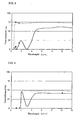
- the measured result is shown by a solid line in Fig. 1.
- Figure 1 also shows by broken lines a measured result obtained by the same method on a sample having the same size as above, formed by using a polycrystalline ZnS sintered body disclosed in Tokukaihei 11-295501 (hereinafter referred to as the conventional ZnS sintered body).
- the conventional ZnS sintered body largely transmits rays having wavelengths ranging from 0.4 to 3 ⁇ m.
- the ZnS sintered body of the present invention not only almost completely blocks rays having wavelengths ranging from 0.4 to 3 ⁇ m but also notably transmits rays having wavelengths ranging from 8 to 12 ⁇ m as shown by the transmittance of more than 65%.
- the transmittance of rays having wavelengths in the vicinity of 2 ⁇ m was about 2.2%.
- the added amount of the Fe 3 O 4 powder has only to be increased. For example, when the added amount was increased to 0.02 wt. %, the transmittance for rays having wavelengths in the vicinity of 2 ⁇ m was reduced to less than 0.5%. However, the transmittance for rays having wavelengths ranging from 8 to 12 ⁇ m was concurrently reduced by about 5%.
- Samples of this example and the conventional ZnS sintered body were subjected to an evaluation test for scattered rays by using laser beams having wavelengths of 830 nm, 1.5 ⁇ m, and 10 ⁇ m. The distance between the sample and the detector was 5 mm. The measured results are also shown in Fig. 1.
- the point " ⁇ " shows the data for the samples of this example; the point " ⁇ ," for the samples of the conventional ZnS sintered body.
- the transmittance measured at the wavelength of 10 ⁇ m is almost the same as that obtained by the spectrophotometer for both this example of the present invention and the conventional ZnS sintered body.
- the transmittance measured by the laser beam becomes higher than that measured by the spectrophotometer.
- the conventional ZnS sintered body exhibits a notable increase as shown by the transmittance of more than 40% at 830 nm.
- This result means that when the conventional ZnS sintered body is used, for example, as the material for a window for an infrared sensor, if the distance between the sensor and the window is small, visible rays can be detected as a noise, thereby decreasing the performance of the sensor.
- this example of the present invention has a transmittance of less than 15% at 830 nm, thereby eliminating the possibility of the above-described performance reduction.
- the data shown in Fig. 1 demonstrate that the additives can directly absorb and block visible rays.
- Example 1 The same ZnS powder as used in Example 1 was prepared as the main constituent. The following powders were prepared as the additives:
- a 0.5 wt. % cobalt powder, a 0.5 wt. % iron powder, and 0.001 wt. % carbon black were added to the ZnS powder.
- the main constituent and additives were mixed for 20 hours by the dry-type ball mill method.
- a formed body was produced and sintered as with Example 1. The top and bottom surfaces of the sintered body were mirror-finished to attain the final shape of a circular disk having a diameter of 55 mm and a thickness of 0.5 mm. The obtained sintered body was dense as shown by the relative density of nearly 100%.
- the in-line transmittance of the obtained sintered body was measured by using a spectrophotometer and a laser by a method similar to that in Example 1. As with Example 1, the measured results are shown by a solid line and the point " ⁇ " in Fig. 2. Figure 2 also shows the measured results on the conventional ZnS sintered body by broken lines and the point " ⁇ ," which are the same data that are shown in Fig. 1. As can be seen from Fig. 2, the ZnS sintered body of the present invention not only blocks rays having wavelengths ranging from 0.4 to 3 ⁇ m to less than 20% but also notably transmits rays having wavelengths ranging from 8 to 12 ⁇ m as shown by the transmittance of more than 65%.
- Fig. 1 The comparison between Fig. 1 and Fig. 2 shows that the additive combination in Example 2 resulted in the high transmittance of about 19% for rays having wavelengths in the vicinity of 2 ⁇ m in comparison with the data obtained by the additive combination in Example 1.
- the measured results by the laser particularly demonstrate that the transmittance for the ray having a wavelength of 830 nm notably reduced to less than 10% in Example 2.
- Example 1 The same ZnS powder as used in Example 1 was prepared as the main constituent. The following powders were prepared as the additives:
- a 0.05 wt. % Fe 3 O 4 powder and a 0.05 wt. % silver powder were added to the ZnS powder.
- the main constituent and additives were mixed for 20 hours by the dry-type ball mill method.
- a formed body was produced and sintered as with Example 1.
- the top and bottom surfaces of the sintered body were mirror-finished to attain the final shape of a circular disk having a diameter of 55 mm and a thickness of 0.5 mm.
- the obtained sintered body had a density of 4.09 Mg ⁇ m -3 , which is nearly the same as the theoretical density, showing that the body was densely sintered.
- the in-line transmittance of the obtained sintered body was measured by using a spectrophotometer and a laser by a method similar to that in Example 1. As with Example 1, the measured results are shown by a solid line and the point " ⁇ " in Fig. 3. Figure 3 also shows the measured results on the conventional ZnS sintered body by broken lines and the point " ⁇ ," which are the same data that are shown in Fig. 1. As can be seen from the measured result by the spectrophotometer, the ZnS sintered body of this example blocks rays having wavelengths ranging from 0.4 to 3 ⁇ m to less than 10% in transmittance.
- this ZnS sintered body is suitable for a filter for an infrared sensor to which rays having wavelengths in this range act as a noise and cause the performance reduction.
- the transmittance for rays having wavelengths of less than 8 ⁇ m decreases and the transmittance for rays having wavelengths ranging from 8 to 12 ⁇ m increases.
- the selection of the types and combination of additives can control the blocking and transmitting properties.
- the measured results by the laser show that the ZnS sintered body of this example notably blocks rays having a shorter wavelength in comparison with the conventional ZnS sintered body.
- Example 1 The same ZnS powder as used in Example 1 was prepared as the main constituent.
- the additives shown in Table 1 were prepared. Each additive was added to the ZnS powder individually.
- the main constituent and additive were mixed for 20 hours by the dry-type ball mill method. Thus, four types of mixed powders were obtained.
- Each powder was formed and sintered as with Example 1.
- the top and bottom surfaces of the sintered body were mirror-finished to attain the final shape of a circular disk having a diameter of 55 mm and a thickness of 0.5 mm.
- Each sintered body thus obtained was dense as shown by the relative density of nearly 100%.
- each sample shows a specific transmitting property over a range from visible rays to near-infrared rays according to the additive used.
- the Fe-added sample can selectively absorb rays having wavelengths ranging from 2 to 4 ⁇ m.
- the Co-added sample selectively absorbs rays having wavelengths ranging from 1 to 2 ⁇ m.
- the Ag-added sample can decrease the transmittance for visible and near-infrared rays as a whole as shown by the decrease to less than 50% in transmittance for rays having wavelengths ranging from 0.4 to 3 ⁇ m.
- the Fe 3 O 4 -added sample can also decrease the transmittance for visible and near-infrared rays as a whole as shown by the decrease to less than 20% in transmittance for rays having wavelengths ranging from 0.4 to 3 ⁇ m. Therefore, a sintered body to which only Fe 3 O 4 is added is suitable for a particular use that requires blocking noise-causing rays having wavelengths ranging from 0.4 to 3 ⁇ m to the lowest possible level.
- a typical example of such an application is a filter for an infrared sensor.
- the measured results by the laser in Fig. 4 also shows that the Co-added and Ag-added samples can block scattered visible rays effectively. As described above, when one type of additive is used, rays having wavelengths in a specific range can be blocked in accordance with the type of the additive used.
- a ceramic material containing ZnS was prepared as the main constituent.
- a ZnS powder having an average particle diameter of 1 ⁇ m and a purity of not less than 99.99 % was prepared as the material for the main constituent.
- the following powders were prepared as the additives:
- a 0.5 wt. % Fe powder and 0.001 wt. % carbon black were added to the ZnS powder.
- the main constituent and additives were mixed by the dry-type ball mill method.
- a formed body was produced and sintered as with Example 1. The sintered body was mirror-finished to attain the shape of a circular disk having a diameter of 30 mm and a thickness of 0.5 mm.
- the in-line transmittance of the obtained sintered body was measured by using a spectrophotometer by a method similar to that in Example 1.
- the measured results are as follows:
- a ceramic material containing ZnSe was prepared as the main constituent.
- a ZnSe powder having an average particle diameter of 1 ⁇ m and a purity of not less than 99.99 % was prepared as the material for the main constituent.
- the following powders were prepared as the additives:
- a 0.5 wt. % Fe powder and 0.001 wt. % carbon black were added to the ZnSe powder.
- the main constituent and additives were mixed and formed as with Example 1.
- the formed body was placed in a graphite mold accompanied by top and bottom punches for a uniaxial pressing system.
- the formed body was heated to 950 °C under a vacuum of 0.15 Pa to be subjected to a pressure of 40 MPa applied by the top punch for one hour.
- This hot-press sintering produced a dense sintered body having a density of 5.41 Mg ⁇ m -3 , or a relative density of 100%.
- the sintered body was mirror-finished to attain the final shape of a circular disk having a diameter of 55 mm and a thickness of 0.5 mm.
- the in-line transmittance of the obtained sintered body was measured by using a spectrophotometer and a laser by a method similar to that in Example 1. As with Example 1, the measured results are shown by a solid line and the point " ⁇ " in Fig. 5. Figure 5 also shows by broken lines and the point " ⁇ " the measured results on a ZnSe sintered body produced without using additives. As can be seen from Fig. 5, the ZnSe sintered body having no additives notably transmits rays having wavelengths of 0.4 ⁇ m and more, i.e., a wide range of rays from visible rays to far-infrared rays.
- the transmittance for rays having wavelengths ranging from 0.4 to 3 ⁇ m can be reduced to less than 25%, with the transmittance for rays having wavelengths ranging from 8 to 12 ⁇ m being maintained at about 60%.
- the measured results by the laser are almost the same as those by the spectrophotometer for both the ZnSe sintered body of this example and the ZnSe sintered body having no additives.
- ZnSe when ZnSe is used as the main constituent, the adverse effect of the scattering of rays can be reduced to a minimum.
- a ceramic material containing Ge as the main constituent was prepared.
- a Ge powder having an average particle diameter of 2 ⁇ m and a purity of not less than 99.99 % was prepared.
- an Fe powder having an average particle diameter of 2 ⁇ m and a purity of 98.2 % was prepared.
- a 0.5 wt. % Fe powder was added to the Ge powder.
- the main constituent and additive were mixed and formed as with Example 1.
- the formed body was placed in a graphite mold accompanied by top and bottom punches for a uniaxial pressing system.
- the formed body was heated to 550 °C under a vacuum of 0.15 Pa to be subjected to a pressure of 40 MPa applied by the top punch for one hour.
- This hot-press sintering produced a dense sintered body having a density of 5.34 Mg ⁇ m -3 , or a relative density of 100%.
- the sintered body was mirror-finished to attain the final shape of a circular disk having a diameter of 55 mm and a thickness of 0.5 mm.
- the in-line transmittance of the obtained sintered body was measured by using a spectrophotometer and a laser by a method similar to that in Example 1.
- the measured results are shown by a solid line and the point " ⁇ " in Fig. 6.
- Figure 6 also shows by broken lines and the point " ⁇ " the measured results on a Ge sintered body produced without using an additive.
- the Ge sintered body having no additive notably transmits rays having wavelengths of 2 ⁇ m and more, i.e., a wide range of rays from near-infrared rays to far-infrared rays.
- the transmittance for rays having wavelengths ranging from 8 to 12 ⁇ m is as low as 40% or so because of the high reflection coefficient of Ge. Therefore, when Ge is used as the main constituent, it is essential to provide an antireflection coating on at least one surface of the sintered body to obtain a transmittance of at least 50%, which is specified in the present invention.
- the antireflection coating may be provided by any known method.
- a ceramic optical component of the present invention has a special optical property in that visible and near-infrared rays are blocked partially or as a whole while far-infrared rays are highly transmitted. This property is rendered by adding to a ceramic material at least one type of additive that blocks visible and near-infrared rays such that the additive is dispersed in the ceramic material unprecedentedly uniformly and minutely. Because of this special property, the present invention can offer a material most suitable for the purpose or use of an optical component, such as a window or lens to be used in a high-performance infrared apparatus.
Landscapes
- Engineering & Computer Science (AREA)
- Chemical & Material Sciences (AREA)
- Ceramic Engineering (AREA)
- Manufacturing & Machinery (AREA)
- Materials Engineering (AREA)
- Structural Engineering (AREA)
- Organic Chemistry (AREA)
- Physics & Mathematics (AREA)
- Nanotechnology (AREA)
- General Physics & Mathematics (AREA)
- Condensed Matter Physics & Semiconductors (AREA)
- Composite Materials (AREA)
- Crystallography & Structural Chemistry (AREA)
- Inorganic Chemistry (AREA)
- Health & Medical Sciences (AREA)
- Toxicology (AREA)
- Optics & Photonics (AREA)
- Compositions Of Oxide Ceramics (AREA)
- Photometry And Measurement Of Optical Pulse Characteristics (AREA)
- Investigating Or Analysing Materials By Optical Means (AREA)
Abstract
Description
| Additive | Average particle diameter (µm) | Purity (%) | Added amount (wt. %) | ||
| a | | 2 | 98.2 | 0.5 | |
| | Co | 1 | 99.9 | 0.5 | |
| | Ag | 2 | 99.9 | 0.05 | |
| d | Fe3O4 | 0.5 | 99.7 | 0.05 |
Claims (8)
- A ceramic optical component consisting mainly of a ceramic material; the component having:(a) a transmittance of at most 50% for rays having wavelengths ranging from 0.4 to 3 µm; and(b) a transmittance of at least 50% for rays having wavelengths ranging from 8 to 12 µm.
- A ceramic optical component consisting mainly of a ceramic material; the component having:(a) a transmittance of at most 30% for rays having wavelengths ranging from 0.4 to 3 µm; and(b) a transmittance of at least 50% for rays having wavelengths ranging from 8 to 12 µm.
- A ceramic optical component consisting mainly of a ceramic material; the component having:(a) a transmittance of at most 5% for rays having wavelengths ranging from 0.4 to 3 µm; and(b) a transmittance of at least 50% for rays having wavelengths ranging from 8 to 12 µm.
- A ceramic optical component as defined in any of claims 1 to 3, wherein the ceramic material is zinc sulfide (ZnS).
- A ceramic optical component as defined in any of claims 1 to 3, wherein the ceramic material is a material selected from the group consisting of zinc selenide (ZnSe) and germanium (Ge).
- A ceramic optical component as defined in any of claims 1 to 3, the component containing an additive that blocks rays having wavelengths ranging from 0.4 to 3 µm.
- A ceramic optical component as defined in claim 6, wherein the additive is at least one material selected from the group consisting of iron, cobalt, silver, carbon black, iron oxide, graphite, diamond, titanium black, copper, nickel, chromium, gold, manganese, molybdenum, tungsten, silicon, germanium, and their compounds.
- A method for producing a ceramic optical component, the method comprising the steps of:(a) preparing a ceramic material by selecting a powder from the group consisting of powders of ZnS, ZnSe, and Ge;(b) preparing an additive by selecting at least one powder from the group consisting of powders of iron, cobalt, silver, carbon black, iron oxide, graphite, diamond, titanium black, copper, nickel, chromium, gold, manganese, molybdenum, tungsten, silicon, germanium, and their compounds;(c) adding the additive to the ceramic material;(d) mixing the ceramic material and the additive;(e) forming the mixture; and(f) sintering the formed body.
Applications Claiming Priority (5)
| Application Number | Priority Date | Filing Date | Title |
|---|---|---|---|
| JP2000368538 | 2000-12-04 | ||
| JP2000368538 | 2000-12-04 | ||
| JP2001297404 | 2001-09-27 | ||
| JP2001297404A JP5257642B2 (en) | 2000-12-04 | 2001-09-27 | Ceramic optical component and manufacturing method thereof |
| PCT/JP2001/010460 WO2002046120A1 (en) | 2000-12-04 | 2001-11-29 | Ceramic optical components and production method therefor |
Publications (3)
| Publication Number | Publication Date |
|---|---|
| EP1340730A1 true EP1340730A1 (en) | 2003-09-03 |
| EP1340730A4 EP1340730A4 (en) | 2005-08-24 |
| EP1340730B1 EP1340730B1 (en) | 2009-05-06 |
Family
ID=26605181
Family Applications (1)
| Application Number | Title | Priority Date | Filing Date |
|---|---|---|---|
| EP01999540A Expired - Lifetime EP1340730B1 (en) | 2000-12-04 | 2001-11-29 | Ceramic optical components and production method therefor |
Country Status (5)
| Country | Link |
|---|---|
| US (1) | US6863842B2 (en) |
| EP (1) | EP1340730B1 (en) |
| JP (1) | JP5257642B2 (en) |
| DE (1) | DE60138642D1 (en) |
| WO (1) | WO2002046120A1 (en) |
Cited By (1)
| Publication number | Priority date | Publication date | Assignee | Title |
|---|---|---|---|---|
| WO2005059013A1 (en) * | 2003-12-15 | 2005-06-30 | E.I. Dupont De Nemours And Company | A process for preparing polymeric films useful for blocking the transmission of near infra red light |
Families Citing this family (20)
| Publication number | Priority date | Publication date | Assignee | Title |
|---|---|---|---|---|
| US8110140B2 (en) * | 2001-12-26 | 2012-02-07 | Sumimoto Electric Industries, Ltd. | Method of manufacturing ceramic optical components |
| JP2003303949A (en) * | 2002-04-11 | 2003-10-24 | Canon Inc | Imaging device |
| JP2005294796A (en) * | 2003-12-19 | 2005-10-20 | Kyocera Corp | Light emitting element storage package, light emitting device, and lighting device |
| US20050247916A1 (en) * | 2004-05-06 | 2005-11-10 | Mccormick Demetrius | Compositions for use in electronics devices |
| JP2006315878A (en) * | 2005-05-10 | 2006-11-24 | Sumitomo Electric Ind Ltd | Translucent ceramics and method for producing the same |
| US7591557B2 (en) * | 2005-05-10 | 2009-09-22 | Wtp Optics, Inc. | Solid state method and apparatus for making lenses and lens components |
| JP2009085996A (en) * | 2007-09-27 | 2009-04-23 | Sumitomo Electric Ind Ltd | Optical component and manufacturing method thereof |
| JP5418231B2 (en) * | 2008-05-23 | 2014-02-19 | 住友電気工業株式会社 | Sintered body, manufacturing method thereof, and optical component |
| DE112009004379T5 (en) * | 2008-12-24 | 2012-05-24 | Murata Manufacturing Co., Ltd. | Infrared ray transmitting optical element and manufacturing method therefor, optical device and optical device |
| US8981630B2 (en) | 2010-09-29 | 2015-03-17 | Kyocera Corporation | Ceramics substrate for mounting light-emitting element and light-emitting device |
| US20130329765A1 (en) * | 2010-12-13 | 2013-12-12 | The Japan Atomic Power Company | Infrared Transmissive Protective Cover, Method for Manufacturing the Same and Monitoring Method Using the Same |
| US10689284B2 (en) * | 2011-02-11 | 2020-06-23 | The Government Of The United States, As Represented By The Secretary Of The Navy | Infrared (IR) transmitting graded index (GRIN) optical elements and method for making same |
| JP5444397B2 (en) | 2012-03-09 | 2014-03-19 | 住友電気工業株式会社 | Manufacturing method of optical components |
| US20130271610A1 (en) | 2012-04-16 | 2013-10-17 | Keith Gregory ROZENBURG | Polycrystalline chalcogenide ceramic material |
| JP5876798B2 (en) * | 2012-09-14 | 2016-03-02 | 住友電気工業株式会社 | ZnSe polycrystal and method for producing the same |
| JP6012537B2 (en) * | 2013-04-22 | 2016-10-25 | 株式会社超高温材料研究センター | Method for producing inorganic material for optical element |
| WO2016163419A1 (en) * | 2015-04-08 | 2016-10-13 | 国立大学法人京都大学 | METHOD FOR PROCESSING Cz-Si FOR INFRARED TRANSMITTING MEMBER, METHOD FOR MANUFACTURING INFRARED TRANSMITTING MEMBER, AND INFRARED TRANSMITTING MEMBER |
| JP6717930B2 (en) * | 2016-03-28 | 2020-07-08 | 富士フイルム株式会社 | Far-infrared transmitting composition, molded body, laminated body, far-infrared transmitting filter, solid-state image sensor and infrared camera |
| JP7580271B2 (en) * | 2017-11-07 | 2024-11-11 | スリーエム イノベイティブ プロパティズ カンパニー | Optical film and system including same |
| EP4220244A4 (en) * | 2020-09-23 | 2024-11-20 | Agc Inc. | FAR-INFRARED RADIATION-TRANSMITTING ELEMENT AND METHOD FOR PRODUCING A FAR-INFRARED RADIATION-TRANSMITTING ELEMENT |
Family Cites Families (21)
| Publication number | Priority date | Publication date | Assignee | Title |
|---|---|---|---|---|
| DE3064976D1 (en) | 1979-11-20 | 1983-10-27 | Nat Res Dev | Infra red reflectors |
| JPS606307B2 (en) | 1980-12-22 | 1985-02-16 | 工業技術院長 | Method for producing polycrystalline zinc selenide |
| US4366141A (en) * | 1981-03-27 | 1982-12-28 | Gte Products Corporation | Treatment of coarse particle size zinc sulfide to improve visual and infrared transmission on hot-pressed articles |
| JPS6139001A (en) | 1984-07-31 | 1986-02-25 | Toshiba Corp | Window material for infrared transmission window |
| JPS61205659A (en) | 1985-03-11 | 1986-09-11 | 防衛庁技術研究本部長 | Manufacture of polycrystal zinc sulfide |
| JPS62284303A (en) | 1986-06-02 | 1987-12-10 | Sumitomo Chem Co Ltd | Composition for far infrared selective permeable filter |
| JPH0786566B2 (en) * | 1987-07-14 | 1995-09-20 | 住友化学工業株式会社 | Far infrared selective transmission filter − |
| US5183602A (en) * | 1989-09-18 | 1993-02-02 | Cornell Research Foundation, Inc. | Infra red diamond composites |
| JP2964786B2 (en) * | 1992-07-01 | 1999-10-18 | 住友電気工業株式会社 | Method for producing translucent barium fluoride sintered body |
| US5502015A (en) * | 1992-07-01 | 1996-03-26 | Sumitomo Electric Industries, Ltd. | Infrared transmitting barium fluoride sintered body |
| JPH0614934U (en) * | 1992-07-28 | 1994-02-25 | 株式会社村田製作所 | Infrared sensor |
| JPH0786566A (en) | 1993-09-17 | 1995-03-31 | Meidensha Corp | Semiconductor device |
| US5575959A (en) * | 1994-04-22 | 1996-11-19 | Hughes Aircraft Company | Process for making low cost infrared windows |
| JP3465121B2 (en) | 1994-08-11 | 2003-11-10 | 竹中エンジニアリング株式会社 | Infrared detector |
| JPH08319150A (en) | 1995-05-18 | 1996-12-03 | Toto Ltd | Ceramic member and its production |
| JPH0921701A (en) | 1995-07-04 | 1997-01-21 | Sumitomo Electric Ind Ltd | Optical window material |
| JP3110325B2 (en) * | 1996-10-02 | 2000-11-20 | 旭テクノグラス株式会社 | Method for adjusting spectral characteristics of near-infrared cut filter glass |
| JP4304733B2 (en) * | 1998-04-14 | 2009-07-29 | 住友電気工業株式会社 | Polycrystalline zinc sulfide optical component and manufacturing method thereof |
| CA2319367C (en) | 1998-11-24 | 2005-04-05 | Nippon Electric Glass Co., Ltd. | Ceramic article |
| JP2000264672A (en) * | 1999-03-16 | 2000-09-26 | Central Glass Co Ltd | Deep green glass |
| JP4193322B2 (en) * | 2000-03-31 | 2008-12-10 | 住友電気工業株式会社 | Lens and infrared sensor using the same |
-
2001
- 2001-09-27 JP JP2001297404A patent/JP5257642B2/en not_active Expired - Fee Related
- 2001-11-29 US US10/182,831 patent/US6863842B2/en not_active Expired - Fee Related
- 2001-11-29 WO PCT/JP2001/010460 patent/WO2002046120A1/en not_active Ceased
- 2001-11-29 DE DE60138642T patent/DE60138642D1/en not_active Expired - Lifetime
- 2001-11-29 EP EP01999540A patent/EP1340730B1/en not_active Expired - Lifetime
Cited By (2)
| Publication number | Priority date | Publication date | Assignee | Title |
|---|---|---|---|---|
| WO2005059013A1 (en) * | 2003-12-15 | 2005-06-30 | E.I. Dupont De Nemours And Company | A process for preparing polymeric films useful for blocking the transmission of near infra red light |
| US7378150B2 (en) | 2003-12-15 | 2008-05-27 | E. I. Du Pont De Nemours And Company | Process for preparing polymeric films useful for blocking the transmission of near infra red light |
Also Published As
| Publication number | Publication date |
|---|---|
| JP2002234774A (en) | 2002-08-23 |
| WO2002046120A1 (en) | 2002-06-13 |
| EP1340730A4 (en) | 2005-08-24 |
| DE60138642D1 (en) | 2009-06-18 |
| EP1340730B1 (en) | 2009-05-06 |
| JP5257642B2 (en) | 2013-08-07 |
| US6863842B2 (en) | 2005-03-08 |
| US20030020887A1 (en) | 2003-01-30 |
Similar Documents
| Publication | Publication Date | Title |
|---|---|---|
| US6863842B2 (en) | Ceramic optical components and production method therefor | |
| EP1139080B1 (en) | Ceramic infrared sensor | |
| EP1460050B1 (en) | Method for producing ceramic optical parts | |
| US5575959A (en) | Process for making low cost infrared windows | |
| WO2012017659A1 (en) | Method for producing sputtering target, and sputtering target | |
| JP4723055B2 (en) | Alumina sintered body, manufacturing method thereof, sintered alumina member and arc tube | |
| US7148480B2 (en) | Polycrystalline optical window materials from nanoceramics | |
| CA2268492C (en) | Optical component, zinc sulfide sintered compact, and fabricating method thereof | |
| CA1303825C (en) | Optically transparent yttrium oxide | |
| US5004712A (en) | Method of producing optically transparent yttrium oxide | |
| EP4470991A1 (en) | Powder and production method therefor | |
| JP2001099941A (en) | Radiation shielding plate, radiation detector, and manufacturing method of radiation shielding plate | |
| KR102036300B1 (en) | Manufacturing method of transparent magnesium aluminate spinel with improved mechanical strength, and transparent magnesium aluminate spinel | |
| KR20190055825A (en) | Transparent spinel sintered body, optical member and method for producing transparent spinel sintered body | |
| Peelen | Alumina: sintering and optical properties | |
| Boyer et al. | Enhanced transparency through second phase crystallization in BaAl4O7 scintillating ceramics | |
| US6261984B1 (en) | Sputtering target and process for the preparation thereof | |
| TW546487B (en) | Ceramics optical part and manufacture method of the same | |
| WO2007004473A1 (en) | Process for producing izo sputtering target | |
| KR100694949B1 (en) | Translucent polycrystalline ceramics and manufacturing method thereof | |
| WO2021111970A1 (en) | Oxide sputtering target and oxide sputtering target production method | |
| EP4456326A1 (en) | Composite member | |
| Dharmakash | Development and Evaluation of Transparent, Aligned Polycrystalline Alumina as an Infrared Window Candidate for Hypersonic Flight Application | |
| EP1008570A1 (en) | Method for producing oxide type ceramic sintered body | |
| Sivakumar | Development and Evaluation of Transparent, Aligned Polycrystalline Alumina as an Infrared Window Candidate for Hypersonic Flight |
Legal Events
| Date | Code | Title | Description |
|---|---|---|---|
| PUAI | Public reference made under article 153(3) epc to a published international application that has entered the european phase |
Free format text: ORIGINAL CODE: 0009012 |
|
| 17P | Request for examination filed |
Effective date: 20020808 |
|
| AK | Designated contracting states |
Kind code of ref document: A1 Designated state(s): AT BE CH CY DE DK ES FI FR GB GR IE IT LI LU MC NL PT SE TR |
|
| RBV | Designated contracting states (corrected) |
Designated state(s): AT BE CH CY DE FR GB IT LI |
|
| A4 | Supplementary search report drawn up and despatched |
Effective date: 20050712 |
|
| RIC1 | Information provided on ipc code assigned before grant |
Ipc: 7G 02B 5/20 B Ipc: 7C 04B 35/547 A Ipc: 7C 04B 35/645 B |
|
| 17Q | First examination report despatched |
Effective date: 20050929 |
|
| GRAP | Despatch of communication of intention to grant a patent |
Free format text: ORIGINAL CODE: EPIDOSNIGR1 |
|
| GRAS | Grant fee paid |
Free format text: ORIGINAL CODE: EPIDOSNIGR3 |
|
| GRAA | (expected) grant |
Free format text: ORIGINAL CODE: 0009210 |
|
| AK | Designated contracting states |
Kind code of ref document: B1 Designated state(s): DE FR GB IT |
|
| REG | Reference to a national code |
Ref country code: GB Ref legal event code: FG4D |
|
| REF | Corresponds to: |
Ref document number: 60138642 Country of ref document: DE Date of ref document: 20090618 Kind code of ref document: P |
|
| PLBE | No opposition filed within time limit |
Free format text: ORIGINAL CODE: 0009261 |
|
| STAA | Information on the status of an ep patent application or granted ep patent |
Free format text: STATUS: NO OPPOSITION FILED WITHIN TIME LIMIT |
|
| 26N | No opposition filed |
Effective date: 20100209 |
|
| PGFP | Annual fee paid to national office [announced via postgrant information from national office to epo] |
Ref country code: IT Payment date: 20091119 Year of fee payment: 9 |
|
| PGFP | Annual fee paid to national office [announced via postgrant information from national office to epo] |
Ref country code: FR Payment date: 20101123 Year of fee payment: 10 |
|
| PGFP | Annual fee paid to national office [announced via postgrant information from national office to epo] |
Ref country code: DE Payment date: 20101124 Year of fee payment: 10 |
|
| PGFP | Annual fee paid to national office [announced via postgrant information from national office to epo] |
Ref country code: GB Payment date: 20101124 Year of fee payment: 10 |
|
| PG25 | Lapsed in a contracting state [announced via postgrant information from national office to epo] |
Ref country code: IT Free format text: LAPSE BECAUSE OF NON-PAYMENT OF DUE FEES Effective date: 20101129 |
|
| GBPC | Gb: european patent ceased through non-payment of renewal fee |
Effective date: 20111129 |
|
| REG | Reference to a national code |
Ref country code: FR Ref legal event code: ST Effective date: 20120731 |
|
| PG25 | Lapsed in a contracting state [announced via postgrant information from national office to epo] |
Ref country code: GB Free format text: LAPSE BECAUSE OF NON-PAYMENT OF DUE FEES Effective date: 20111129 |
|
| PG25 | Lapsed in a contracting state [announced via postgrant information from national office to epo] |
Ref country code: FR Free format text: LAPSE BECAUSE OF NON-PAYMENT OF DUE FEES Effective date: 20111130 |
|
| REG | Reference to a national code |
Ref country code: DE Ref legal event code: R119 Ref document number: 60138642 Country of ref document: DE Effective date: 20130601 |
|
| PG25 | Lapsed in a contracting state [announced via postgrant information from national office to epo] |
Ref country code: DE Free format text: LAPSE BECAUSE OF NON-PAYMENT OF DUE FEES Effective date: 20130601 |