EP1340689A2 - Bande d'attache en métal - Google Patents
Bande d'attache en métal Download PDFInfo
- Publication number
- EP1340689A2 EP1340689A2 EP03250937A EP03250937A EP1340689A2 EP 1340689 A2 EP1340689 A2 EP 1340689A2 EP 03250937 A EP03250937 A EP 03250937A EP 03250937 A EP03250937 A EP 03250937A EP 1340689 A2 EP1340689 A2 EP 1340689A2
- Authority
- EP
- European Patent Office
- Prior art keywords
- head
- strap
- tie
- passage
- metal banding
- Prior art date
- Legal status (The legal status is an assumption and is not a legal conclusion. Google has not performed a legal analysis and makes no representation as to the accuracy of the status listed.)
- Withdrawn
Links
Images


Classifications
-
- F—MECHANICAL ENGINEERING; LIGHTING; HEATING; WEAPONS; BLASTING
- F16—ENGINEERING ELEMENTS AND UNITS; GENERAL MEASURES FOR PRODUCING AND MAINTAINING EFFECTIVE FUNCTIONING OF MACHINES OR INSTALLATIONS; THERMAL INSULATION IN GENERAL
- F16L—PIPES; JOINTS OR FITTINGS FOR PIPES; SUPPORTS FOR PIPES, CABLES OR PROTECTIVE TUBING; MEANS FOR THERMAL INSULATION IN GENERAL
- F16L3/00—Supports for pipes, cables or protective tubing, e.g. hangers, holders, clamps, cleats, clips, brackets
- F16L3/22—Supports for pipes, cables or protective tubing, e.g. hangers, holders, clamps, cleats, clips, brackets specially adapted for supporting a number of parallel pipes at intervals
- F16L3/23—Supports for pipes, cables or protective tubing, e.g. hangers, holders, clamps, cleats, clips, brackets specially adapted for supporting a number of parallel pipes at intervals for a bundle of pipes or a plurality of pipes placed side by side in contact with each other
- F16L3/233—Supports for pipes, cables or protective tubing, e.g. hangers, holders, clamps, cleats, clips, brackets specially adapted for supporting a number of parallel pipes at intervals for a bundle of pipes or a plurality of pipes placed side by side in contact with each other by means of a flexible band
- F16L3/2338—Supports for pipes, cables or protective tubing, e.g. hangers, holders, clamps, cleats, clips, brackets specially adapted for supporting a number of parallel pipes at intervals for a bundle of pipes or a plurality of pipes placed side by side in contact with each other by means of a flexible band having at least one metal locking barb
Definitions
- This invention relates to a metal banding tie.
- Metal banding ties are known for securing articles together securely.
- one such tie comprises a flat head or buckle 10, which is formed of a stamped sheet of metal.
- a bridge 11 is formed in the head to define a passage 12 which is directed across the head 10 in the plane thereof.
- a pair of spaced upstanding tabs 13 are formed on the outer end of the head.
- a length of metal banding in the form of a flat strap 14 is cut from a roll and fastened at one end to the head 10, as shown in Figure 2 of the drawings.
- the strap 14 is fastened to the head 10 by feeding it across the head 10 from its inner end to its outer end, through the passageway 12.
- the strap is then folded downwardly through 180° around the outer end of the head 10 and fed back under the head 10, where it is passed through the opening formed under the bridge 11 to the top surface of the head 10. In this manner, the strap 14 is securely fastened at one end to the head.
- the tie can be used to fasten objects together by forming the strap 14 into a loop around the articles to be fastened, and inserting its free second end through the passage 12 in the head 10.
- the strap 14 is then tightened and secured by folding it back on itself through about 90° over the bridge 12, whereupon the strap tensioning force can be released and any excess length of strap 14 can be cut off.
- the strap 14 is then permanently secured by folding it completely back on itself before folding the tabs 13 inwardly to constrain the cut end, as shown.
- the tie provides an extremely strong fastening around objects.
- such ties are difficult and time consuming to secure, particularly if any degree of tension is required in the strap.
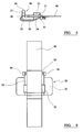
- the projecting length of strap is then fed into an upwardly-inclined passageway 18 formed in the tool 19 and the flat head 10 of the tie is constrained between a pair of jaws 20,21 of the tool.
- the tie is then tensioned by pulling the projecting the projecting length of strap further through the head 10 along the upwardly-inclined passageway 18 in direction A.
- the tensioned strap is then temporarily clamped to the head 10, whilst a blade 22 in the tool cuts the strap in the passageway 18, at a point remote from the head 10 of the tie.
- a folding member 23 of the tool is then advanced towards the head 10 of the tie in direction B, to abut the underside of the projecting length of strap and to fold the latter back over the head 10, so as to permanently secure the tie.
- the folding member 23 is then further driven to fold the upstanding tabs 13 on the head downwardly and towards each other onto the folded strap portion, to constrain the folded strap portion.
- a metal banding tie comprising a substantially flat head and a flexible strap extending outwardly from an inner end of the head, a raised bridge being provided on the head to define a through passage across the plane of the head, for receiving the strap when the strap is formed into a loop about the object(s) to be tied and its free end inserted into the passage from a first end to a second end, a pair of upstanding tabs being disposed on respective opposite sides of the passage adjacent the first end thereof, the outer ends of the tabs converging towards each other and being separated at their outer ends by a space which is equal to or greater than the width of the strap.
- the tabs are much easier to fold towards each other using the above-mentioned tool, because their outer ends are already angled in the direction in which they have to be folded.
- the inner end of the tabs are separated from each other by a distance which is substantially greater than the width of the strap, in order to allow sufficient room for the tabs to converge and still leave a space between their outer ends which is equal to or greater than the width of the strap.
- the inner end of the tabs are separated from each other by a distance which is substantially equal to the width of the strap, the lower ends of the tabs diverging outwardly, in order to allow sufficient room for the tabs to then converge and still leave a space between their outer ends which is equal to or greater than the width of the strap.
- a plurality of bends are pre-formed in the tabs about distinct fold lines which extend transversely across the tabs in the direction of the passage. These fold lines assist in ensuring that the tabs fold correctly and also help to weaken the tabs slightly, thereby making them easier to fold.
- the tabs converge from respective fold lines.
- a head for attaching to an elongate flexible metal strap, the head being substantially flat and comprising a raised bridge which defines a through passage across the plane of the head, for receiving the strap when the strap is formed into a loop about the object(s) to be tied and its free end inserted into the passage from a first end to a second end, a pair of upstanding tabs being disposed on respective opposite sides of the passage adjacent the first end thereof, the outer ends of the tabs converging towards each other and being separated by a space which is equal to or greater than the width of the strap which the passage is arranged to receive.
- a metal banding tie comprising a substantially flat head and a flexible strap attached at a first end thereof to the head and extending outwardly from an inner end of the head, a raised bridge being provided on the head to define a through passage across the top surface of the head, for receiving the strap when the strap is formed into a loop about the object(s) to be tied and its second end inserted into the passage from a first end to a second end, the first end of the strap extending through the passage from the second end to the first end and being folded around an outer end of the head to extend back on itself under the head and through an aperture formed under the bridge onto the upper surface of the head, the first end of the strap then extending downwardly around the inner end of the head.
- a metal banding tie comprising a head having substantially flat body portion provided with a formation on its front surface defining a through passage for receiving a strap of the tie when the strap is formed into a loop about the object(s) to be tied and its free end inserted into the passage, the rear surface of the body of the head having an outwardly-extending formation arranged to abut the surface of an object about which the tie is applied.
- the outwardly-extending formation on the rear of the body of the head abuts a surface of an object about which the tie is applied and thereby acts as a stand-off which keeps the body of the tie away from the surface of the object and allows the jaws of the tool to be freely disengaged from the body of the head.
- the formation on the rear of the body of the head is resiliently compressible against the body of the head.
- a plurality of formations are provided on the rear of the body of the head.
- a pair of formations are provided on opposite side edges of the body of the head on a line which extends transverse thereof, perpendicular to the longitudinal axis of the strap.
- the head is formed as a one-piece from a sheet of metal, the formations comprising tabs which extend outwardly from opposite side edges of the body of the head.
- the tabs are folded inwardly towards each other.
- a problem of tensioning ties using a tool is that the head of the tie needs to be located correctly in the jaws of the tool, otherwise the tool could jam or an unsatisfactory fastening could be formed. Also, there is a risk that persons could jam or damage the tool by using a conventional type of tie which is not designed for use in a tool.
- a metal banding tie comprising a substantially flat head having front and rear edges arranged to engage with a fastening tool, at least one of said edges being provided with a formation for engaging with a complimentary formation on the tool.
- the or each of the formations on the tie engages with the complimentary formation on the tool, thereby ensuring that the tie engages correctly with the tool and preventing the tie from displacing during tensioning.
- the formations also prevent incorrect ties from being used, particularly if at least one formation on the tie is a cut-out which receives a complimentary projection on the tool, since it will not be possible to fit a tie to the tool unless it has the appropriate cut-out for receiving the projection on the tool.
- the cut-out is a v-shaped notch formed in the edge of the tie.
- two formations are formed on at least one of the edges of the tie.
- the tie comprises and a flexible strap extending outwardly from an inner end of the head, a raised bridge being provided on the head to define a through passage across the plane of the head, for receiving the strap when the strap is formed into a loop about the object(s) to be tied and its free end inserted into the passage from a first end to a second end, a pair of upstanding tabs being disposed on respective opposite sides of the passage adjacent the first end thereof, the formations being formed on opposite sides of the passage on the outer end of the head.
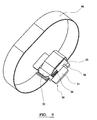
- FIG. 5 to 9 of the drawings there is shown a metal banding tie intended for use with a banding tool of the type shown in Figure 4.
- the tie comprises a substantially flat head 30 formed from a single sheet of metal and a separate elongate flat strap 40.
- the head comprises a rectangular body portion 31 having inner, outer and opposite side edges.
- a recessed passageway 32 extends across the body 31 between the inner and outer side edges thereof.
- the passageway 32 is slightly wider than the width of the strap 40.
- a bridge 33 extends across the passageway 32 at a point intermediate its opposite ends.
- An aperture 34 is formed across the floor of the passageway 32, below the bridge 33.
- the head 30 further comprises an extension portion 35 which extends outwardly from the floor of the passageway 32 on the outer side edge of the body portion 31 of the head 30.
- the extension portion 35 comprises a pair of upstanding tabs 36 on its respective opposite side edges.
- the lower ends of the tabs 36 are aligned with respective opposite sides of the passageway 32 and are separated from each other by a distance which is slightly greater than the width of the passageway 32.
- the tabs 36 diverge outwardly to respective fold lines 38 which extend transverse the tabs in the direction of the passageway 32.
- the tabs 36 then extend parallel to each other in a direction perpendicular to the plane of the head 30.
- the upper ends of the tabs 36 then converge inwardly from respective fold lines 37 to their respective outermost points, which are separated from each other by a distance which is slightly greater than the width of the strap 40.
- the end of the strap 40 is folded back on itself in a C-shaped formation.
- the folded end is then folded through 90° at a point several millimetres away from the end, in a direction away from the main portion of the strap 40.
- the opposite end of the strap 40 is then passed between the tabs 36 and into the passageway 32 under the bridge 33.
- the strap 40 is then pulled through the head 30 until the folded end of the strap passes under the head 30, whereupon the folded end is manoeuvred through the aperture 36 into the passageway 32 on the top surface of the head.
- the portion at the end of the strap which is folded through 90° is then engaged over the edge of the inner edge of the body 31 of the head 30.
- the strap 40 is formed into a loop around the object(s) to be tied and its free end inserted between the tab 36 into the passageway 32.
- the length of strap projecting through the bridge 33 is then fed into an upwardly-inclined passageway formed in the fastening tool, shown in Figure 4.
- the outer edge of the body 31 of the head 30 is initially engaged with the outer jaw 21.
- the body of the tool is then pivoted downwardly, about the point where the outer jaw 21 engages the head 30, to bring the inner jaw 20 into a position where it engages the inner edge of the body 31 of the head 10.
- the tie is then tensioned by pulling the projecting length of strap further through the head 30 along the upwardly-inclined passageway of the tool, as hereinbefore described.
- the tensioned strap is then temporarily clamped to the head 30, whilst the blade in the tool cuts the strap in the passageway of the tool, at a point remote from the head 30 of the tie.
- the folding member of the tool is then advanced towards the head 30 of the tie, in a direction which extends parallel to, but above, the plane of the head 30, until it abuts the underside of the projecting length of strap and folds the latter through 180°back over the bridge 33 of the head 30, so as to permanently secure the tie.
- the folding member is then further driven until it abuts the converging upper ends of the tabs 36 and folds the them inwardly towards each other.
- the underside of the leading edge of the folding member is preferably provided with a formation or grooves having divergent inwardly-facing walls which are arranged to respectively abut the tabs and fold them inwardly as the outer end of the folding member passes over the tabs 36.
- the tabs 36 are relatively easy to fold towards each other using the above-mentioned tool, because their outer ends are already angled in the direction in which they have to be folded.
- the preformed fold lines 37,38 on the tabs 36 also weaken the tabs 36, so they are more inclined to fold.
- a pair of tabs 50 are provided on opposite side edges of the body 31 of the head.
- the tabs 50 are bent inwardly towards each other on the underside of the head, the tabs 50 extending beyond the floor of the passage 32, so that they form the lowermost portion of the head.
- the tabs 50 project beyond the underside of the jaws and thus abut the surface of an object about which the tie is applied.
- the tie remains fully tensioned even when the tie is disengaged.
- the tabs 50 are resiliently deformed slightly towards the underside of the body 31 of the head 30 and thus help to maintain the strap tension.
- FIG. 12 of the drawings there is shown the head of a metal banding tie which is similar to the tie of Figures 5 to 9 and like parts are given like reference numerals.
- a pair of v-shaped notches 60 are formed in the edge of the head 30 at the outer end thereof on opposite sides of the passageway 32.
- the v-shaped notches 60 in the head 30 engage with complimentary v-shaped projections (not shown) on the jaws 20, 21 of the tool, thereby ensuring that the tie engages correctly with the tool and preventing the tie from displacing during tensioning.
- the formations also prevent incorrect ties from being used with the tool.
- the v-shaped notches 60 can be formed in the edge of the head 30 at the inner end thereof on opposite sides of the passageway 32.
- a tie in accordance with this invention can thus be reliably and consistently tensioned, cut and secured using a banding tool of the type disclosed in our co-pending UK Patent Application No.0203966.7.
Applications Claiming Priority (6)
| Application Number | Priority Date | Filing Date | Title |
|---|---|---|---|
| GB0204711 | 2002-02-28 | ||
| GB0204711A GB0204711D0 (en) | 2002-02-28 | 2002-02-28 | Metal banding tie |
| GB0206518A GB0206518D0 (en) | 2002-02-28 | 2002-03-19 | Metal banding tie |
| GB0206518 | 2002-03-19 | ||
| GB0300982A GB2385787B (en) | 2002-02-28 | 2003-01-16 | Metal banding tie |
| GB0300982 | 2003-01-16 |
Publications (2)
| Publication Number | Publication Date |
|---|---|
| EP1340689A2 true EP1340689A2 (fr) | 2003-09-03 |
| EP1340689A3 EP1340689A3 (fr) | 2004-04-07 |
Family
ID=27738833
Family Applications (1)
| Application Number | Title | Priority Date | Filing Date |
|---|---|---|---|
| EP03250937A Withdrawn EP1340689A3 (fr) | 2002-02-28 | 2003-02-15 | Bande d'attache en métal |
Country Status (2)
| Country | Link |
|---|---|
| EP (1) | EP1340689A3 (fr) |
| GB (3) | GB2409643B (fr) |
Cited By (1)
| Publication number | Priority date | Publication date | Assignee | Title |
|---|---|---|---|---|
| FR3022531A1 (fr) * | 2014-06-23 | 2015-12-25 | Caillau Ets | Collier de serrage a boucle transversale |
Citations (5)
| Publication number | Priority date | Publication date | Assignee | Title |
|---|---|---|---|---|
| GB367440A (en) * | 1930-11-20 | 1932-02-22 | Daniel Ambrose Bradley | Improvements in or relating to fasteners for bands or straps |
| US4015311A (en) * | 1976-04-28 | 1977-04-05 | Illinois Tool Works Inc. | Buckle with a visual tension indicator |
| EP0094168A1 (fr) * | 1982-05-06 | 1983-11-16 | Robert Arthur Henderson Heard | Agrafe pour le raccordement d'une bande |
| EP0187693A2 (fr) * | 1985-01-07 | 1986-07-16 | Silver Fox Limited | Boucle pour liens |
| DE20104180U1 (de) * | 2001-03-10 | 2001-06-13 | Neko Gmbh | Stahlbinder |
Family Cites Families (4)
| Publication number | Priority date | Publication date | Assignee | Title |
|---|---|---|---|---|
| US4541146A (en) * | 1984-03-05 | 1985-09-17 | Duro Dyne Corporation | Cinching clamp device and method of attachment |
| US4866817A (en) * | 1984-03-16 | 1989-09-19 | Panduit Corp. | Buckle fastener and method of application |
| US4696327A (en) * | 1986-06-18 | 1987-09-29 | Electro Adapter | Band finishing tool |
| GB0203966D0 (en) * | 2002-02-19 | 2002-04-03 | Spirent Plc | Banding tool |
-
2003
- 2003-01-16 GB GB0505332A patent/GB2409643B/en not_active Expired - Fee Related
- 2003-01-16 GB GB0505329A patent/GB2409642B/en not_active Expired - Fee Related
- 2003-01-16 GB GB0505327A patent/GB2409641B/en not_active Expired - Fee Related
- 2003-02-15 EP EP03250937A patent/EP1340689A3/fr not_active Withdrawn
Patent Citations (5)
| Publication number | Priority date | Publication date | Assignee | Title |
|---|---|---|---|---|
| GB367440A (en) * | 1930-11-20 | 1932-02-22 | Daniel Ambrose Bradley | Improvements in or relating to fasteners for bands or straps |
| US4015311A (en) * | 1976-04-28 | 1977-04-05 | Illinois Tool Works Inc. | Buckle with a visual tension indicator |
| EP0094168A1 (fr) * | 1982-05-06 | 1983-11-16 | Robert Arthur Henderson Heard | Agrafe pour le raccordement d'une bande |
| EP0187693A2 (fr) * | 1985-01-07 | 1986-07-16 | Silver Fox Limited | Boucle pour liens |
| DE20104180U1 (de) * | 2001-03-10 | 2001-06-13 | Neko Gmbh | Stahlbinder |
Cited By (3)
| Publication number | Priority date | Publication date | Assignee | Title |
|---|---|---|---|---|
| FR3022531A1 (fr) * | 2014-06-23 | 2015-12-25 | Caillau Ets | Collier de serrage a boucle transversale |
| WO2015197961A1 (fr) * | 2014-06-23 | 2015-12-30 | Etablissements Caillau | Collier de serrage a boucle transversale |
| US10399754B2 (en) | 2014-06-23 | 2019-09-03 | Etablissements Caillau | Clamping collar with a transverse buckle |
Also Published As
| Publication number | Publication date |
|---|---|
| EP1340689A3 (fr) | 2004-04-07 |
| GB2409642B (en) | 2005-09-14 |
| GB0505329D0 (en) | 2005-04-20 |
| GB2409641B (en) | 2005-11-09 |
| GB2409643B (en) | 2005-09-14 |
| GB0505327D0 (en) | 2005-04-20 |
| GB2409643A (en) | 2005-07-06 |
| GB0505332D0 (en) | 2005-04-20 |
| GB2409642A (en) | 2005-07-06 |
| GB2409641A (en) | 2005-07-06 |
Similar Documents
| Publication | Publication Date | Title |
|---|---|---|
| US7392570B2 (en) | Concave buckle for strap | |
| KR101277475B1 (ko) | 신속 부착형 티볼트 클램프 | |
| EP0971845B1 (fr) | Attache de cable en ligne | |
| EP0235997B1 (fr) | Attache de câble | |
| EP0329689B1 (fr) | Organe de fixation | |
| GB2123477A (en) | Band clamp | |
| US4422217A (en) | Packaging fastener | |
| JPH09189377A (ja) | ケーブル・タイ・ストラップ | |
| US20110167594A1 (en) | Plastic clamp | |
| US5927497A (en) | Pack of large surface washers | |
| US10774953B1 (en) | Cable tie | |
| KR20130099945A (ko) | 스트랩 지지체를 가진 버클 | |
| US4866817A (en) | Buckle fastener and method of application | |
| GB2385787A (en) | Metal banding tie | |
| EP1340689A2 (fr) | Bande d'attache en métal | |
| TW201139911A (en) | Cable tie | |
| EP2521676A1 (fr) | Attache | |
| CA2512773A1 (fr) | Dispositif de fixation de chauffe-eau | |
| US20110016673A1 (en) | Band Seal With Selectively Deployable Locking Member | |
| CA2382237C (fr) | Attache pour le bois a piece verrouillable | |
| EP1338513A1 (fr) | Dispositif à serrer des bandes | |
| JPH10147361A (ja) | バンドクランプ | |
| JP7393251B2 (ja) | 土留部材 | |
| EP0918021A2 (fr) | Collier de serrage en matière plastique | |
| EP0746833B1 (fr) | Dispositif de montage |
Legal Events
| Date | Code | Title | Description |
|---|---|---|---|
| PUAI | Public reference made under article 153(3) epc to a published international application that has entered the european phase |
Free format text: ORIGINAL CODE: 0009012 |
|
| AK | Designated contracting states |
Kind code of ref document: A2 Designated state(s): AT BE BG CH CY CZ DE DK EE ES FI FR GB GR HU IE IT LI LU MC NL PT SE SI SK TR |
|
| AX | Request for extension of the european patent |
Extension state: AL LT LV MK RO |
|
| RIC1 | Information provided on ipc code assigned before grant |
Ipc: 7B 65D 63/06 B Ipc: 7B 65D 63/08 A |
|
| PUAL | Search report despatched |
Free format text: ORIGINAL CODE: 0009013 |
|
| AK | Designated contracting states |
Kind code of ref document: A3 Designated state(s): AT BE BG CH CY CZ DE DK EE ES FI FR GB GR HU IE IT LI LU MC NL PT SE SI SK TR |
|
| AX | Request for extension of the european patent |
Extension state: AL LT LV MK RO |
|
| 17P | Request for examination filed |
Effective date: 20041007 |
|
| AKX | Designation fees paid |
Designated state(s): DE FR IT |
|
| RAP1 | Party data changed (applicant data changed or rights of an application transferred) |
Owner name: HELLERMANNTYTON LIMITED |
|
| RAP1 | Party data changed (applicant data changed or rights of an application transferred) |
Owner name: HELLERMANNTYTON LIMITED |
|
| STAA | Information on the status of an ep patent application or granted ep patent |
Free format text: STATUS: THE APPLICATION IS DEEMED TO BE WITHDRAWN |
|
| 18D | Application deemed to be withdrawn |
Effective date: 20070901 |