EP1340677B1 - Timing gates for a packaging machine - Google Patents
Timing gates for a packaging machine Download PDFInfo
- Publication number
- EP1340677B1 EP1340677B1 EP03251033A EP03251033A EP1340677B1 EP 1340677 B1 EP1340677 B1 EP 1340677B1 EP 03251033 A EP03251033 A EP 03251033A EP 03251033 A EP03251033 A EP 03251033A EP 1340677 B1 EP1340677 B1 EP 1340677B1
- Authority
- EP
- European Patent Office
- Prior art keywords
- assembly
- product
- batches
- chute portion
- gates
- Prior art date
- Legal status (The legal status is an assumption and is not a legal conclusion. Google has not performed a legal analysis and makes no representation as to the accuracy of the status listed.)
- Revoked
Links
Images
Classifications
-
- B—PERFORMING OPERATIONS; TRANSPORTING
- B65—CONVEYING; PACKING; STORING; HANDLING THIN OR FILAMENTARY MATERIAL
- B65B—MACHINES, APPARATUS OR DEVICES FOR, OR METHODS OF, PACKAGING ARTICLES OR MATERIALS; UNPACKING
- B65B1/00—Packaging fluent solid material, e.g. powders, granular or loose fibrous material, loose masses of small articles, in individual containers or receptacles, e.g. bags, sacks, boxes, cartons, cans, or jars
- B65B1/30—Devices or methods for controlling or determining the quantity or quality or the material fed or filled
- B65B1/40—Devices or methods for controlling or determining the quantity or quality or the material fed or filled by timing of filling operations
- B65B1/42—Devices or methods for controlling or determining the quantity or quality or the material fed or filled by timing of filling operations and arresting flow by cut-off means
Definitions
- the present invention relates to a product delivery chute assembly for packaging machines.
- a product delivery chute assembly to extend between a weigher that provides batches of product and a packaging machine former that receives the batches to deliver the batches to the interior of tubular bag material, said assembly including:
- the timing gates are mounted in the upper chute portion so as to release product to be delivered to the lower chute portion.
- the upper chute portion has a lower edge surrounding an upper chute portion lower opening through which the product is delivered to the lower chute portion.
- the timing gates are located adjacent the upper chute portion lower opening.
- each trough is defined between a pair of flanges which project inwardly with respect to said axis.
- the weigher 10 includes a plurarily of buckets 14 which weigh the material and deliver the weighed batches of product to the chute assembly 11.
- the chute assembly 11 includes an upper chute portion 15 and a lower chute portion 16.
- the upper chute portion 15 includes a side wall 17 of frusto conical configuration. More particular, the side wall 17 is downwardly converging from an upper edge 19 to a lower edge 20.
- the lower chute portion 16 has a side wall 18 of parabolic configuration, converging from an upper edge 21 to a lower edge 22.
- the lower edge 22 encompasses an opening through which product is delivered to the former 12.
- the upper edge 19 encompasses an opening through which the product is delivered from the weigher 10.
- a timing gate device 23 including a mounting 24 upon which there is pivotally mounted a plurality of gates 25.
- the gates 25 are movable between a closed position (as depicted) blocking the flow of product from the weigher 10 to the former 12, and an open position allowing the flow of product.
- Each gate 25 is pivotally moved by means of a motor 26 that is operated in phase with operation of the abovementioned packaging machine.
- the gates 25 are located between the edges 19 and 22 and more particularly intermediate the edges 19 and 22. More preferably, the gates 25 engage the side wall 17 adjacent the lower edge 20 of the upper chute portion 15.
- the above described preferred embodiment has the advantage of engaging the product at a speed well below the speed that it would have reached had it been allowed to travel freely to the edge 22. Still further, when the product is released from the gates 25, it will gain velocity so that it will have an increased velocity when entering the former 12, relative to an arrangement in which the gates are located adjacent to former 12.
Abstract
Description
- The present invention relates to a product delivery chute assembly for packaging machines.
- It is known to have a weigher to deliver batches of product to a chute extending toward a packaging machine former. A strip of bag material is delivered to the former and formed into tubular bag material thereby. Product is delivered to the interior of the tubular bag material so that upon longitudinal and transverse sealing of the tubular bag material, discreet bags of product can be provided by the packaging machine.
- Batches of the product must be delivered to the former in a timed sequence in phase with the packaging machine. Typically, delivery of the product to the former is governed by means of timing gates located beneath the chute but above the former. The gates are driven so that they open and close at appropriate times in phase with the operation of the packaging machine. US 6119438 discloses a product chute delivery assembly according to the preamble of claim 1.
- The above discussed arrangement has the disadvantage that product engaged by the gate is travelling relatively fast and can be damaged. This is particularly the case with snack foods such as potato crisps.
- A still further disadvantage is that when the product reaches the former, it is travelling relatively slow and therefore can often block the former.
- It is the object of the present invention to overcome or substantially ameliorate at least one of the above disadvantages.
- There is disclosed herein a product delivery chute assembly to extend between a weigher that provides batches of product and a packaging machine former that receives the batches to deliver the batches to the interior of tubular bag material, said assembly including:
- a chute having a generally vertical longitudinal axis and a side wall surrounding said axis and converging downwardly from an upper chute portion to a lower chute portion, the lower chute portion surrounding a lower opening through which product batches are delivered to the former, the upper portion surrounding an upper opening through which product batches are delivered from the weigher; said assembly characterised by including: a plurality of troughs extending down said side wall and along which the batches travel after being delivered thereto by said weigher; and a timing gate device including timing gates in the chute and a motor assembly operably associated with the gates to cause movement thereof between a first position blocking the passage of the product batches along the troughs so as to retain a batch or batches of said product, and a second position releasing the batch or batches of product for movement along the chute for delivery to the lower opening, each gate being operatively associated with a respective one of the troughs to engage the batch or batches traveling along the trough.
- Preferably, the timing gates are mounted in the upper chute portion so as to release product to be delivered to the lower chute portion.
- Preferably, the upper chute portion has a lower edge surrounding an upper chute portion lower opening through which the product is delivered to the lower chute portion.
- Preferably, the timing gates are located adjacent the upper chute portion lower opening.
- Preferably, each trough is defined between a pair of flanges which project inwardly with respect to said axis.
- Preferably, each gate pivots about a generally horizontal axis generally normal to the respective flanges.
- A preferred form of the present invention will now be described by way of example with reference to the accompanying drawings wherein:
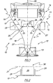
- Figure 1 is a schematic part sectioned side elevation of a weigher, former and product delivery chute assembly therebetween; and
- Figure 2 is a schematic end elevation of portion of the chute employed in the chute assembly of Figure 1.
- In the accompanying drawings, there is schematically depicted a weigher 10 to deliver weighed batches of product to a
chute assembly 11. Thechute assembly 11 delivers the batches of product to a former 12 located above a packaging machine (not illustrated). Theassembly 11 has a substantially vertical central axis. - The former 12 includes a
former shoulder 13 through which a strip of bag material passes to be formed into a tubular configuration. The tubular bag material is longitudinally and transversely sealed and transversely cut so that discreet bags of product are formed. Product entering the former 12 is delivered to the interior of the tubular bag material. - The
weigher 10 includes a plurarily ofbuckets 14 which weigh the material and deliver the weighed batches of product to thechute assembly 11. Thechute assembly 11 includes anupper chute portion 15 and alower chute portion 16. Theupper chute portion 15 includes aside wall 17 of frusto conical configuration. More particular, theside wall 17 is downwardly converging from anupper edge 19 to alower edge 20. Thelower chute portion 16 has aside wall 18 of parabolic configuration, converging from anupper edge 21 to alower edge 22. Thelower edge 22 encompasses an opening through which product is delivered to the former 12. Theupper edge 19 encompasses an opening through which the product is delivered from theweigher 10. - Mounted within the
chute assembly 11 is atiming gate device 23 including amounting 24 upon which there is pivotally mounted a plurality ofgates 25. Thegates 25 are movable between a closed position (as depicted) blocking the flow of product from theweigher 10 to the former 12, and an open position allowing the flow of product. Eachgate 25 is pivotally moved by means of a motor 26 that is operated in phase with operation of the abovementioned packaging machine. In this respect, it should be appreciated that thegates 25 are located between theedges edges gates 25 engage theside wall 17 adjacent thelower edge 20 of theupper chute portion 15. - The
upper chute portion 15 andlower chute portion 16 surround a generally verticallongitudinal axis 28. More particularly theinternal surface 27 of theside walls 17 also surrounds theaxis 28. - To aid in retaining the batches of product the
surface 27 is provided with a plurality of inwardly projectingflanges 29 that are arranged angularly about theaxis 28 and extend downwardly towards theedge 20. Each adjacent pair offlanges 29 co-operates to provide a trough 30 along which the batches of product pass. - Located between each pair of
flanges 29 is a respective one of thegates 25. Eachgate 25 pivots about a generallyhorizontal axis 31 that extends generally normal with respect to theflanges 29. - The above described preferred embodiment has the advantage of engaging the product at a speed well below the speed that it would have reached had it been allowed to travel freely to the
edge 22. Still further, when the product is released from thegates 25, it will gain velocity so that it will have an increased velocity when entering the former 12, relative to an arrangement in which the gates are located adjacent to former 12.
Claims (10)
- A product delivery chute assembly (11) to extend between a weigher (10) that provides batches of product and a packaging machine former (12) that receives the batches to deliver the batches to the interior of tubular bag material, said assembly (11) including:a chute (15, 16) having a generally vertical longitudinal axis (28) and a side wall (17, 18) surrounding said axis (28) and converging downwardly from an upper chute portion (15) to a lower chute portion (16), the lower chute portion (16) surrounding a lower opening through which product batches are delivered to the former (12), the upper chute portion (15) surrounding an upper opening through which product batches are delivered from the weigher (10);said assembly (11) characterised by including:a plurality of troughs (30) extending down said side wall (17,18) and along which the batches travel after being delivered thereto by said weigher (10); anda timing gate device (23) including timing gates (25) in the chute (15, 16) and a motor assembly (26) operably associated with the gates (25) to cause movement thereof between a first position blocking the passage of the product batches along the troughs (30) so as to retain a batch or batches of said product, and a second position releasing the batch or batches of product for movement along the trough (30) for delivery to the lower opening, each gate (25) being operatively associated with a respective one of the troughs (30) to engage the batch or batches traveling along the trough (30).
- The assembly (11) of claim 1, wherein the timing gates (25) are mounted in the upper chute portion (15) so as to release product to be delivered to the lower chute portion (16), with the upper chute portion (15) also having said troughs (30).
- The assembly (11) of claim 2, wherein the upper chute portion (15) has a lower edge (20) surrounding an upper chute portion lower opening through which the product is delivered to the lower chute portion (16).
- The assembly (11) of claim 3, wherein the timing gates (25) are located adjacent the upper chute portion lower opening.
- The assembly (11) of claim 4, wherein each trough (30) is defined between a pair of flanges (29) which project inwardly with respect to said axis (28).
- The assembly (11) of claim 5, wherein the gates (25) each pivot about a generally horizontal axis (31) generally normal to the respective flanges (29).
- The assembly (11) of claim 3, wherein the troughs (30) extend from adjacent the upper chute portion upper opening to adjacent the upper chute portion lower opening.
- The assembly (11) of claim 1, wherein the troughs (30) are provided by a plurality of flanges (29) spaced angularly about said longitudinal axis (28) and project inwardly with respect thereto from said side wall (17, 18), the flanges (29) extending longitudinally downwardly so as to direct product moving downwardly along the chute (15, 16).
- The assembly (11) of claim 8, wherein said upper chute portion (15) has said flanges (29).
- The assembly (11) of claim 4, wherein said gates (25) are mounted in said upper chute portion (15).
Applications Claiming Priority (2)
| Application Number | Priority Date | Filing Date | Title |
|---|---|---|---|
| AUPS070602 | 2002-02-22 | ||
| AUPS0706A AUPS070602A0 (en) | 2002-02-22 | 2002-02-22 | Timing gates for a packaging machine |
Publications (3)
| Publication Number | Publication Date |
|---|---|
| EP1340677A2 EP1340677A2 (en) | 2003-09-03 |
| EP1340677A3 EP1340677A3 (en) | 2004-04-28 |
| EP1340677B1 true EP1340677B1 (en) | 2006-10-25 |
Family
ID=3834305
Family Applications (1)
| Application Number | Title | Priority Date | Filing Date |
|---|---|---|---|
| EP03251033A Revoked EP1340677B1 (en) | 2002-02-22 | 2003-02-20 | Timing gates for a packaging machine |
Country Status (8)
| Country | Link |
|---|---|
| US (1) | US7310923B2 (en) |
| EP (1) | EP1340677B1 (en) |
| JP (1) | JP2003292129A (en) |
| AT (1) | ATE343518T1 (en) |
| AU (1) | AUPS070602A0 (en) |
| BR (1) | BR0300221A (en) |
| DE (1) | DE60309230T2 (en) |
| ES (1) | ES2271478T3 (en) |
Families Citing this family (7)
| Publication number | Priority date | Publication date | Assignee | Title |
|---|---|---|---|---|
| JP4046289B2 (en) * | 2004-11-18 | 2008-02-13 | 勝三 川西 | Combination scale |
| EP1768904B1 (en) * | 2005-06-08 | 2008-12-17 | Multipond Wägetechnik GmbH | Filling apparatus |
| JP4781801B2 (en) * | 2005-12-01 | 2011-09-28 | 株式会社イシダ | Weighing device |
| DE102007019246A1 (en) * | 2007-04-24 | 2008-10-30 | Hastamat Verpackungstechnik Gmbh | Apparatus and method for combining a number of portions of a bar-shaped, lumpy or pourable product and for the synchronized transfer of the portions for connection to a partial combination weigher |
| AU2008221530B2 (en) * | 2007-11-26 | 2010-07-01 | Tna Australia Pty Limited | A scale for a packaging machine |
| WO2009128379A1 (en) | 2008-04-17 | 2009-10-22 | 株式会社イシダ | Combination measuring device |
| US8546704B1 (en) * | 2010-06-16 | 2013-10-01 | Maurice Minardi | Precise count high volume preform delivery system |
Family Cites Families (23)
| Publication number | Priority date | Publication date | Assignee | Title |
|---|---|---|---|---|
| US3070931A (en) * | 1961-01-10 | 1963-01-01 | Gen Packaging Equip Co | Packaging machine |
| US3842569A (en) * | 1973-06-07 | 1974-10-22 | Filper Corp | Carrot bagging apparatus and method |
| US4193465A (en) * | 1978-01-27 | 1980-03-18 | The Woodman Company, Inc. | Scale hopper door mechanism |
| AU541709B2 (en) * | 1981-08-18 | 1985-01-17 | K.K. Ishida Koki Seisakusho | Combinatorial weighing apparatus |
| JPS5847137U (en) * | 1981-09-22 | 1983-03-30 | 株式会社石田衡器製作所 | Article discharge device in automatic weighing equipment |
| US4538692A (en) * | 1982-02-01 | 1985-09-03 | Kliklok Corporation | Method and apparatus for combination weighing with multiple storage cups for each scale hopper |
| JPS6077910A (en) | 1983-10-03 | 1985-05-02 | Nippon Steel Corp | Structure of opening and closing part of flow rate regulating valve |
| JPS6077909A (en) | 1983-10-03 | 1985-05-02 | Nippon Steel Corp | Process for opening and closing flow rate regulating valve |
| DE3837709A1 (en) * | 1988-11-07 | 1990-05-10 | Rovema Gmbh | TUBE BAG MACHINE |
| US5235794A (en) * | 1992-07-01 | 1993-08-17 | Recot, Inc. | Bag making apparatus and method |
| AU670196B2 (en) * | 1992-12-14 | 1996-07-04 | J.R. Simplot Company | Vacuum pack machine for french fries |
| JPH08114492A (en) | 1994-10-17 | 1996-05-07 | Ishida Co Ltd | Combined measuring instrument |
| JP3469340B2 (en) * | 1995-01-19 | 2003-11-25 | 株式会社イシダ | Combination weighing device |
| US5753867A (en) * | 1995-02-02 | 1998-05-19 | Ishida Co., Ltd., | Combinational weighing apparatus |
| AU693034B2 (en) * | 1995-06-30 | 1998-06-18 | Kliklok Corporation | Improved transitional product flow and adaptive control |
| JP3091122B2 (en) * | 1995-09-04 | 2000-09-25 | ハウス食品株式会社 | Solid filling apparatus and solid filling method using the same |
| US6428457B1 (en) * | 1995-09-29 | 2002-08-06 | Ishida Co., Ltd. | Former for a bag maker |
| US6000200A (en) * | 1997-10-17 | 1999-12-14 | Yakima Wire Works | Bagging apparatus |
| US6421987B1 (en) | 1999-01-08 | 2002-07-23 | Ishida Co., Ltd. | Latitudinal sealing mechanism for bag-packaging machine and a bag packaging machine having the same |
| JP4302821B2 (en) * | 1999-06-22 | 2009-07-29 | 株式会社イシダ | Weighing and bag making and packaging system |
| WO2001048448A1 (en) * | 1999-12-24 | 2001-07-05 | Ishida Co., Ltd. | Combination weighing and counting device |
| US6351926B1 (en) * | 2000-01-19 | 2002-03-05 | Automated Packaging Systems, Inc. | Packaging system |
| JP2001289702A (en) | 2000-04-03 | 2001-10-19 | Ishida Co Ltd | Combined weighing-counting device |
-
2002
- 2002-02-22 AU AUPS0706A patent/AUPS070602A0/en not_active Abandoned
-
2003
- 2003-02-20 ES ES03251033T patent/ES2271478T3/en not_active Expired - Lifetime
- 2003-02-20 DE DE60309230T patent/DE60309230T2/en not_active Revoked
- 2003-02-20 AT AT03251033T patent/ATE343518T1/en not_active IP Right Cessation
- 2003-02-20 EP EP03251033A patent/EP1340677B1/en not_active Revoked
- 2003-02-21 JP JP2003044427A patent/JP2003292129A/en not_active Withdrawn
- 2003-02-21 US US10/371,161 patent/US7310923B2/en not_active Expired - Fee Related
- 2003-02-21 BR BR0300221-7A patent/BR0300221A/en not_active IP Right Cessation
Also Published As
| Publication number | Publication date |
|---|---|
| AUPS070602A0 (en) | 2002-03-21 |
| BR0300221A (en) | 2004-08-03 |
| EP1340677A3 (en) | 2004-04-28 |
| ATE343518T1 (en) | 2006-11-15 |
| US7310923B2 (en) | 2007-12-25 |
| JP2003292129A (en) | 2003-10-15 |
| US20030230594A1 (en) | 2003-12-18 |
| EP1340677A2 (en) | 2003-09-03 |
| DE60309230D1 (en) | 2006-12-07 |
| ES2271478T3 (en) | 2007-04-16 |
| DE60309230T2 (en) | 2007-03-01 |
Similar Documents
| Publication | Publication Date | Title |
|---|---|---|
| AU2014279317B2 (en) | Packing method and packaging device for implementing packing method | |
| EP1340677B1 (en) | Timing gates for a packaging machine | |
| JP5015639B2 (en) | Linking device and weighing device, packaging device and weighing packaging system using the same | |
| US4569446A (en) | Method and apparatus for feeding a product including fines | |
| US4081004A (en) | Weighing hopper and method | |
| EP1164365B1 (en) | Combination weighing and counting device | |
| US2320581A (en) | Apparatus for conveying and filling cartons | |
| US5178256A (en) | Loader machine | |
| EP1338872B1 (en) | Guide troughs for weighing buckets and chutes | |
| US5014499A (en) | Stretch stress relief for bag thermo-cross-seals in vertical form, fill and seal machines | |
| EP0181738B1 (en) | Flow control apparatus | |
| US4693285A (en) | Automatic container-filling apparatus | |
| US3239108A (en) | Feeder pan and gate for packaging machines | |
| US11021280B2 (en) | Former chute | |
| US10858128B2 (en) | Packaging assembly | |
| EP3792605B1 (en) | Timing hopper and combination weighing device | |
| US2732989A (en) | harker | |
| AU2003200587A1 (en) | Timing Gates for a Packaging Machine | |
| JP2022139074A (en) | Bag making packaging device | |
| WO1993010027A1 (en) | Vertical conveyor | |
| EP1817232B1 (en) | Metering device for feeding loose granular substances | |
| AU2003200524B2 (en) | Guide Troughs for Weighing Buckets and Chutes | |
| CN106965985B (en) | A kind of blanking device of powder material material bag | |
| KR20190095774A (en) | Semi-automatic salt packing machine | |
| CN207346180U (en) | Quantitative automatic packing scale |
Legal Events
| Date | Code | Title | Description |
|---|---|---|---|
| PUAI | Public reference made under article 153(3) epc to a published international application that has entered the european phase |
Free format text: ORIGINAL CODE: 0009012 |
|
| AK | Designated contracting states |
Kind code of ref document: A2 Designated state(s): AT BE BG CH CY CZ DE DK EE ES FI FR GB GR HU IE IT LI LU MC NL PT SE SI SK TR |
|
| AX | Request for extension of the european patent |
Extension state: AL LT LV MK RO |
|
| PUAL | Search report despatched |
Free format text: ORIGINAL CODE: 0009013 |
|
| AK | Designated contracting states |
Kind code of ref document: A3 Designated state(s): AT BE BG CH CY CZ DE DK EE ES FI FR GB GR HU IE IT LI LU MC NL PT SE SI SK TR |
|
| AX | Request for extension of the european patent |
Extension state: AL LT LV MK RO |
|
| 17P | Request for examination filed |
Effective date: 20040913 |
|
| AKX | Designation fees paid |
Designated state(s): AT BE BG CH CY CZ DE DK EE ES FI FR GB GR HU IE IT LI LU MC NL PT SE SI SK TR |
|
| 17Q | First examination report despatched |
Effective date: 20050405 |
|
| GRAP | Despatch of communication of intention to grant a patent |
Free format text: ORIGINAL CODE: EPIDOSNIGR1 |
|
| GRAS | Grant fee paid |
Free format text: ORIGINAL CODE: EPIDOSNIGR3 |
|
| GRAA | (expected) grant |
Free format text: ORIGINAL CODE: 0009210 |
|
| AK | Designated contracting states |
Kind code of ref document: B1 Designated state(s): AT BE BG CH CY CZ DE DK EE ES FI FR GB GR HU IE IT LI LU MC NL PT SE SI SK TR |
|
| PG25 | Lapsed in a contracting state [announced via postgrant information from national office to epo] |
Ref country code: SK Free format text: LAPSE BECAUSE OF FAILURE TO SUBMIT A TRANSLATION OF THE DESCRIPTION OR TO PAY THE FEE WITHIN THE PRESCRIBED TIME-LIMIT Effective date: 20061025 Ref country code: CH Free format text: LAPSE BECAUSE OF FAILURE TO SUBMIT A TRANSLATION OF THE DESCRIPTION OR TO PAY THE FEE WITHIN THE PRESCRIBED TIME-LIMIT Effective date: 20061025 Ref country code: AT Free format text: LAPSE BECAUSE OF FAILURE TO SUBMIT A TRANSLATION OF THE DESCRIPTION OR TO PAY THE FEE WITHIN THE PRESCRIBED TIME-LIMIT Effective date: 20061025 Ref country code: BE Free format text: LAPSE BECAUSE OF FAILURE TO SUBMIT A TRANSLATION OF THE DESCRIPTION OR TO PAY THE FEE WITHIN THE PRESCRIBED TIME-LIMIT Effective date: 20061025 Ref country code: NL Free format text: LAPSE BECAUSE OF FAILURE TO SUBMIT A TRANSLATION OF THE DESCRIPTION OR TO PAY THE FEE WITHIN THE PRESCRIBED TIME-LIMIT Effective date: 20061025 Ref country code: SI Free format text: LAPSE BECAUSE OF FAILURE TO SUBMIT A TRANSLATION OF THE DESCRIPTION OR TO PAY THE FEE WITHIN THE PRESCRIBED TIME-LIMIT Effective date: 20061025 Ref country code: CZ Free format text: LAPSE BECAUSE OF FAILURE TO SUBMIT A TRANSLATION OF THE DESCRIPTION OR TO PAY THE FEE WITHIN THE PRESCRIBED TIME-LIMIT Effective date: 20061025 Ref country code: LI Free format text: LAPSE BECAUSE OF FAILURE TO SUBMIT A TRANSLATION OF THE DESCRIPTION OR TO PAY THE FEE WITHIN THE PRESCRIBED TIME-LIMIT Effective date: 20061025 Ref country code: FI Free format text: LAPSE BECAUSE OF FAILURE TO SUBMIT A TRANSLATION OF THE DESCRIPTION OR TO PAY THE FEE WITHIN THE PRESCRIBED TIME-LIMIT Effective date: 20061025 |
|
| REG | Reference to a national code |
Ref country code: GB Ref legal event code: FG4D |
|
| REG | Reference to a national code |
Ref country code: CH Ref legal event code: EP |
|
| REG | Reference to a national code |
Ref country code: IE Ref legal event code: FG4D |
|
| REF | Corresponds to: |
Ref document number: 60309230 Country of ref document: DE Date of ref document: 20061207 Kind code of ref document: P |
|
| PG25 | Lapsed in a contracting state [announced via postgrant information from national office to epo] |
Ref country code: DK Free format text: LAPSE BECAUSE OF FAILURE TO SUBMIT A TRANSLATION OF THE DESCRIPTION OR TO PAY THE FEE WITHIN THE PRESCRIBED TIME-LIMIT Effective date: 20070125 Ref country code: SE Free format text: LAPSE BECAUSE OF FAILURE TO SUBMIT A TRANSLATION OF THE DESCRIPTION OR TO PAY THE FEE WITHIN THE PRESCRIBED TIME-LIMIT Effective date: 20070125 Ref country code: BG Free format text: LAPSE BECAUSE OF FAILURE TO SUBMIT A TRANSLATION OF THE DESCRIPTION OR TO PAY THE FEE WITHIN THE PRESCRIBED TIME-LIMIT Effective date: 20070125 |
|
| PG25 | Lapsed in a contracting state [announced via postgrant information from national office to epo] |
Ref country code: MC Free format text: LAPSE BECAUSE OF NON-PAYMENT OF DUE FEES Effective date: 20070228 |
|
| PG25 | Lapsed in a contracting state [announced via postgrant information from national office to epo] |
Ref country code: PT Free format text: LAPSE BECAUSE OF FAILURE TO SUBMIT A TRANSLATION OF THE DESCRIPTION OR TO PAY THE FEE WITHIN THE PRESCRIBED TIME-LIMIT Effective date: 20070326 |
|
| NLV1 | Nl: lapsed or annulled due to failure to fulfill the requirements of art. 29p and 29m of the patents act | ||
| REG | Reference to a national code |
Ref country code: ES Ref legal event code: FG2A Ref document number: 2271478 Country of ref document: ES Kind code of ref document: T3 |
|
| REG | Reference to a national code |
Ref country code: CH Ref legal event code: PL |
|
| EN | Fr: translation not filed | ||
| PLBI | Opposition filed |
Free format text: ORIGINAL CODE: 0009260 |
|
| 26 | Opposition filed |
Opponent name: ISHIDA CO., LTD. Effective date: 20070720 |
|
| PLAX | Notice of opposition and request to file observation + time limit sent |
Free format text: ORIGINAL CODE: EPIDOSNOBS2 |
|
| PLBB | Reply of patent proprietor to notice(s) of opposition received |
Free format text: ORIGINAL CODE: EPIDOSNOBS3 |
|
| PG25 | Lapsed in a contracting state [announced via postgrant information from national office to epo] |
Ref country code: IE Free format text: LAPSE BECAUSE OF NON-PAYMENT OF DUE FEES Effective date: 20070220 |
|
| PG25 | Lapsed in a contracting state [announced via postgrant information from national office to epo] |
Ref country code: FR Free format text: LAPSE BECAUSE OF FAILURE TO SUBMIT A TRANSLATION OF THE DESCRIPTION OR TO PAY THE FEE WITHIN THE PRESCRIBED TIME-LIMIT Effective date: 20070608 |
|
| PGFP | Annual fee paid to national office [announced via postgrant information from national office to epo] |
Ref country code: ES Payment date: 20080324 Year of fee payment: 6 |
|
| PGFP | Annual fee paid to national office [announced via postgrant information from national office to epo] |
Ref country code: DE Payment date: 20080214 Year of fee payment: 6 Ref country code: GB Payment date: 20080220 Year of fee payment: 6 Ref country code: IT Payment date: 20080227 Year of fee payment: 6 |
|
| PLAB | Opposition data, opponent's data or that of the opponent's representative modified |
Free format text: ORIGINAL CODE: 0009299OPPO |
|
| PG25 | Lapsed in a contracting state [announced via postgrant information from national office to epo] |
Ref country code: FR Free format text: LAPSE BECAUSE OF FAILURE TO SUBMIT A TRANSLATION OF THE DESCRIPTION OR TO PAY THE FEE WITHIN THE PRESCRIBED TIME-LIMIT Effective date: 20061025 |
|
| RDAF | Communication despatched that patent is revoked |
Free format text: ORIGINAL CODE: EPIDOSNREV1 |
|
| PG25 | Lapsed in a contracting state [announced via postgrant information from national office to epo] |
Ref country code: EE Free format text: LAPSE BECAUSE OF FAILURE TO SUBMIT A TRANSLATION OF THE DESCRIPTION OR TO PAY THE FEE WITHIN THE PRESCRIBED TIME-LIMIT Effective date: 20061025 |
|
| RDAG | Patent revoked |
Free format text: ORIGINAL CODE: 0009271 |
|
| STAA | Information on the status of an ep patent application or granted ep patent |
Free format text: STATUS: PATENT REVOKED |
|
| 27W | Patent revoked |
Effective date: 20090123 |
|
| GBPR | Gb: patent revoked under art. 102 of the ep convention designating the uk as contracting state |
Effective date: 20090123 |
|
| PG25 | Lapsed in a contracting state [announced via postgrant information from national office to epo] |
Ref country code: LU Free format text: LAPSE BECAUSE OF FAILURE TO SUBMIT A TRANSLATION OF THE DESCRIPTION OR TO PAY THE FEE WITHIN THE PRESCRIBED TIME-LIMIT Effective date: 20070220 Ref country code: CY Free format text: LAPSE BECAUSE OF FAILURE TO SUBMIT A TRANSLATION OF THE DESCRIPTION OR TO PAY THE FEE WITHIN THE PRESCRIBED TIME-LIMIT Effective date: 20061025 |
|
| PG25 | Lapsed in a contracting state [announced via postgrant information from national office to epo] |
Ref country code: HU Free format text: LAPSE BECAUSE OF FAILURE TO SUBMIT A TRANSLATION OF THE DESCRIPTION OR TO PAY THE FEE WITHIN THE PRESCRIBED TIME-LIMIT Effective date: 20070426 Ref country code: TR Free format text: LAPSE BECAUSE OF FAILURE TO SUBMIT A TRANSLATION OF THE DESCRIPTION OR TO PAY THE FEE WITHIN THE PRESCRIBED TIME-LIMIT Effective date: 20061025 |
|
| PG25 | Lapsed in a contracting state [announced via postgrant information from national office to epo] |
Ref country code: GR Free format text: LAPSE BECAUSE OF NON-PAYMENT OF DUE FEES Effective date: 20070228 |