EP1339179A2 - Bi-directional optical transmission system, and master and slave stations used therefor - Google Patents
Bi-directional optical transmission system, and master and slave stations used therefor Download PDFInfo
- Publication number
- EP1339179A2 EP1339179A2 EP03003870A EP03003870A EP1339179A2 EP 1339179 A2 EP1339179 A2 EP 1339179A2 EP 03003870 A EP03003870 A EP 03003870A EP 03003870 A EP03003870 A EP 03003870A EP 1339179 A2 EP1339179 A2 EP 1339179A2
- Authority
- EP
- European Patent Office
- Prior art keywords
- optical
- electrical
- signal
- converter
- upstream
- Prior art date
- Legal status (The legal status is an assumption and is not a legal conclusion. Google has not performed a legal analysis and makes no representation as to the accuracy of the status listed.)
- Withdrawn
Links
Images


Classifications
-
- H—ELECTRICITY
- H04—ELECTRIC COMMUNICATION TECHNIQUE
- H04J—MULTIPLEX COMMUNICATION
- H04J14/00—Optical multiplex systems
- H04J14/02—Wavelength-division multiplex systems
- H04J14/0201—Add-and-drop multiplexing
- H04J14/0215—Architecture aspects
- H04J14/0216—Bidirectional architectures
-
- H—ELECTRICITY
- H04—ELECTRIC COMMUNICATION TECHNIQUE
- H04B—TRANSMISSION
- H04B10/00—Transmission systems employing electromagnetic waves other than radio-waves, e.g. infrared, visible or ultraviolet light, or employing corpuscular radiation, e.g. quantum communication
- H04B10/25—Arrangements specific to fibre transmission
- H04B10/2575—Radio-over-fibre, e.g. radio frequency signal modulated onto an optical carrier
- H04B10/25752—Optical arrangements for wireless networks
- H04B10/25753—Distribution optical network, e.g. between a base station and a plurality of remote units
- H04B10/25755—Ring network topology
-
- H—ELECTRICITY
- H04—ELECTRIC COMMUNICATION TECHNIQUE
- H04B—TRANSMISSION
- H04B10/00—Transmission systems employing electromagnetic waves other than radio-waves, e.g. infrared, visible or ultraviolet light, or employing corpuscular radiation, e.g. quantum communication
- H04B10/25—Arrangements specific to fibre transmission
- H04B10/2589—Bidirectional transmission
-
- H—ELECTRICITY
- H04—ELECTRIC COMMUNICATION TECHNIQUE
- H04B—TRANSMISSION
- H04B10/00—Transmission systems employing electromagnetic waves other than radio-waves, e.g. infrared, visible or ultraviolet light, or employing corpuscular radiation, e.g. quantum communication
- H04B10/50—Transmitters
-
- H—ELECTRICITY
- H04—ELECTRIC COMMUNICATION TECHNIQUE
- H04J—MULTIPLEX COMMUNICATION
- H04J14/00—Optical multiplex systems
- H04J14/02—Wavelength-division multiplex systems
- H04J14/0201—Add-and-drop multiplexing
- H04J14/0202—Arrangements therefor
- H04J14/0204—Broadcast and select arrangements, e.g. with an optical splitter at the input before adding or dropping
-
- H—ELECTRICITY
- H04—ELECTRIC COMMUNICATION TECHNIQUE
- H04J—MULTIPLEX COMMUNICATION
- H04J14/00—Optical multiplex systems
- H04J14/02—Wavelength-division multiplex systems
- H04J14/0201—Add-and-drop multiplexing
- H04J14/0202—Arrangements therefor
- H04J14/0205—Select and combine arrangements, e.g. with an optical combiner at the output after adding or dropping
-
- H—ELECTRICITY
- H04—ELECTRIC COMMUNICATION TECHNIQUE
- H04J—MULTIPLEX COMMUNICATION
- H04J14/00—Optical multiplex systems
- H04J14/02—Wavelength-division multiplex systems
- H04J14/0201—Add-and-drop multiplexing
- H04J14/0202—Arrangements therefor
- H04J14/0206—Express channels arrangements
-
- H—ELECTRICITY
- H04—ELECTRIC COMMUNICATION TECHNIQUE
- H04J—MULTIPLEX COMMUNICATION
- H04J14/00—Optical multiplex systems
- H04J14/02—Wavelength-division multiplex systems
- H04J14/0226—Fixed carrier allocation, e.g. according to service
-
- H—ELECTRICITY
- H04—ELECTRIC COMMUNICATION TECHNIQUE
- H04J—MULTIPLEX COMMUNICATION
- H04J14/00—Optical multiplex systems
- H04J14/02—Wavelength-division multiplex systems
- H04J14/0227—Operation, administration, maintenance or provisioning [OAMP] of WDM networks, e.g. media access, routing or wavelength allocation
- H04J14/0241—Wavelength allocation for communications one-to-one, e.g. unicasting wavelengths
- H04J14/0242—Wavelength allocation for communications one-to-one, e.g. unicasting wavelengths in WDM-PON
- H04J14/0245—Wavelength allocation for communications one-to-one, e.g. unicasting wavelengths in WDM-PON for downstream transmission, e.g. optical line terminal [OLT] to ONU
- H04J14/0246—Wavelength allocation for communications one-to-one, e.g. unicasting wavelengths in WDM-PON for downstream transmission, e.g. optical line terminal [OLT] to ONU using one wavelength per ONU
-
- H—ELECTRICITY
- H04—ELECTRIC COMMUNICATION TECHNIQUE
- H04J—MULTIPLEX COMMUNICATION
- H04J14/00—Optical multiplex systems
- H04J14/02—Wavelength-division multiplex systems
- H04J14/0227—Operation, administration, maintenance or provisioning [OAMP] of WDM networks, e.g. media access, routing or wavelength allocation
- H04J14/0241—Wavelength allocation for communications one-to-one, e.g. unicasting wavelengths
- H04J14/0242—Wavelength allocation for communications one-to-one, e.g. unicasting wavelengths in WDM-PON
- H04J14/0249—Wavelength allocation for communications one-to-one, e.g. unicasting wavelengths in WDM-PON for upstream transmission, e.g. ONU-to-OLT or ONU-to-ONU
- H04J14/025—Wavelength allocation for communications one-to-one, e.g. unicasting wavelengths in WDM-PON for upstream transmission, e.g. ONU-to-OLT or ONU-to-ONU using one wavelength per ONU, e.g. for transmissions from-ONU-to-OLT or from-ONU-to-ONU
-
- H—ELECTRICITY
- H04—ELECTRIC COMMUNICATION TECHNIQUE
- H04J—MULTIPLEX COMMUNICATION
- H04J14/00—Optical multiplex systems
- H04J14/02—Wavelength-division multiplex systems
- H04J14/0278—WDM optical network architectures
- H04J14/028—WDM bus architectures
-
- H—ELECTRICITY
- H04—ELECTRIC COMMUNICATION TECHNIQUE
- H04J—MULTIPLEX COMMUNICATION
- H04J14/00—Optical multiplex systems
- H04J14/02—Wavelength-division multiplex systems
- H04J14/0278—WDM optical network architectures
- H04J14/0282—WDM tree architectures
-
- G—PHYSICS
- G02—OPTICS
- G02B—OPTICAL ELEMENTS, SYSTEMS OR APPARATUS
- G02B6/00—Light guides; Structural details of arrangements comprising light guides and other optical elements, e.g. couplings
- G02B6/24—Coupling light guides
- G02B6/26—Optical coupling means
- G02B6/28—Optical coupling means having data bus means, i.e. plural waveguides interconnected and providing an inherently bidirectional system by mixing and splitting signals
- G02B6/293—Optical coupling means having data bus means, i.e. plural waveguides interconnected and providing an inherently bidirectional system by mixing and splitting signals with wavelength selective means
- G02B6/29346—Optical coupling means having data bus means, i.e. plural waveguides interconnected and providing an inherently bidirectional system by mixing and splitting signals with wavelength selective means operating by wave or beam interference
- G02B6/29361—Interference filters, e.g. multilayer coatings, thin film filters, dichroic splitters or mirrors based on multilayers, WDM filters
-
- H—ELECTRICITY
- H04—ELECTRIC COMMUNICATION TECHNIQUE
- H04J—MULTIPLEX COMMUNICATION
- H04J14/00—Optical multiplex systems
- H04J14/02—Wavelength-division multiplex systems
- H04J14/0298—Wavelength-division multiplex systems with sub-carrier multiplexing [SCM]
Abstract
Description
the master station and the slave stations are connected to each other via a single optical fiber,
the master station transmits a downstream optical signal to each of the slave stations via the single optical fiber, and each of the slave stations transmits an upstream optical signal to the master station via the single optical fiber,
the master station includes:
each of the slave stations includes:
the delay adjusting circuit adjusts the phase based on a predetermined amount of delay.
the delay adjusting circuit may adjust the phase based on the feedback of the electrical signal obtained by the combiner.
the delay adjusting circuit adjusts the phase based on a predetermined amount of delay.
the delay adjusting circuit may adjust the phase based on the feedback of the electrical signal obtained by the combiner.
the first optical exchange element may be a wavelength multiplexing coupler for supplying the downstream optical signal only to the single optical fiber and supplying the upstream optical signal only to the first optical-electrical converter, and
the second optical exchange element may be a wavelength multiplexing coupler for supplying the upstream optical signal only to the single optical fiber and supplying the downstream optical signal only to the second optical-electrical converter.
the second electrical-optical converter may output an upstream optical signal having a large amount of wavelength dispersion in the single optical fiber. With this, it is possible to reduce influences of degradation in transmission quality due to wavelength dispersion on the optical fiber in both of the upstream and downstream systems.
the master station may further include an optical attenuator placed between the first optical exchange element and the first electrical-optical converter.
each of the slave station may further include an optical attenuator placed between the second optical exchange element and the second electrical-optical converter.
the master station may further include an optical isolator placed between the first optical exchange element and the first electrical-optical converter.
each of the slave station may further include an optical isolator placed between the second optical exchange element and the second electrical-optical converter.
the first and/or second optical exchange element may be an optical branching unit for branching an optical signal transmitted through the single optical fiber into two optical signals.
each of the slave stations may further include a frequency converter for converting a frequency of the electrical signal output from the second optical-electrical converter to a frequency band of the electrical signal supplied to the first electrical-optical converter. Thus, it is possible to get the downstream electrical signal back to the frequency band of the upstream electrical signal.
a radio communications area of one group overlaps with another radio communications area of another group,
- a second electrical-optical converter for converting an electrical signal to the upstream optical signal;
- a second optical-electrical converter for converting the downstream optical signal to an electrical signal; and
- a second optical exchange element, provided between the single optical fiber, and the second electrical-optical converter and the second optical-electrical converter, for outputting the upstream optical signal supplied by the second electrical-optical converter to the single optical fiber and outputting the downstream optical signal transmitted through the single optical fiber to the second optical-electrical converter.
the delay adjusting circuit adjusts the phase based on a predetermined amount of delay.
the delay adjusting circuit may adjust the phase based on the feedback of the electrical signal obtained by the combiner.
the delay adjusting circuit adjusts the phase based on a predetermined amount of delay.
the delay adjusting circuit may adjust the phase based on the feedback of the electrical signal obtained by the combiner.
- a second electric-optical converter for converting an electrical signal to an upstream optical signal having a wavelength assigned to the slave station;
- a second optical-electrical converter for converting the downstream optical signal to an electrical signal; and
- an optical add/drop unit, provided between the single optical fiber, and the second electrical-optical converter and the second optical-electrical converter, for outputting the upstream optical signal supplied by the second electrical-optical converter to the single optical fiber and outputting only a downstream optical signal having a wavelength assigned to the slave station from out of the downstream optical signals transmitted through the single optical fiber to the second optical-electrical converter.
Claims (44)
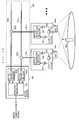
- A system for bi-directional optical communications between a master station (400) and a plurality of slave stations (500a, 500b, 500c), whereineach of the slave stations includes:the master station and the slave stations are connected to each other via a single optical fiber,the master station transmits a downstream optical signal to each of the slave stations via the single optical fiber, and each of the slave stations transmits an upstream optical signal to the master station via the single optical fiber,the master station includes:a first electrical-optical converter (403) for converting an electrical signal to the downstream optical signal;a first optical-electrical converter (404) for converting the upstream optical signal to an electrical signal; anda first optical exchange element (405), provided between the single optical fiber, and the first electrical-optical converter and the first optical-electrical converter, for outputting the downstream optical signal supplied by the first electrical-optical converter to the single optical fiber and outputting the upstream optical signal transmitted through the single optical fiber to the first optical-electrical converter, anda second electrical-optical converter (503) for converting an electrical signal to the upstream optical signal;a second optical-electrical converter (504) for converting the downstream optical signal to an electrical'signal; anda second optical exchange element (505), provided between the single optical fiber, and the second electrical-optical converter and the second optical-electrical converter, for outputting the upstream optical signal supplied by the second electrical-optical converter to the single optical fiber and outputting the downstream optical signal transmitted through the single optical fiber to the second optical-electrical converter.
- The bi-directional optical transmission system according to claim 1, whereinthe master station further includes:a signal level adjusting circuit (454) for adjusting an amplitude of an electrical signal, and outputting the amplitude-adjusted electrical signal;a delay adjusting circuit (455) for adjusting a phase of the electrical signal outputted from the signal level adjusting circuit, and outputting the phase-adjusted electrical signal; anda combiner (457) for combining the electrical signal outputted from the delay adjusting circuit and the electrical signal outputted from the first optical-electrical converter.
- The bi-directional optical transmission system according to claim 2, whereinthe signal level adjusting circuit adjusts the amplitude based on a predetermined amplitude value, andthe delay adjusting circuit adjusts the phase based on a predetermined amount of delay.
- The bi-directional optical transmission system according to claim 2, whereinthe signal level adjusting circuit adjusts the amplitude based on a feedback of an electrical signal obtained by the combiner, andthe delay adjusting circuit adjusts the phase based on the feedback of the electrical signal obtained by the combiner.
- The bi-directional optical transmission system according to claim 1, wherein
each of the slave stations further includes:a signal level adjusting circuit (554) for adjusting an amplitude of an electrical signal, and outputting the amplitude-adjusted electrical signal;a delay adjusting circuit (555) for adjusting a phase of the electrical signal outputted from the signal level adjusting circuit, and outputting the phase-adjusted electrical signal; anda combiner (557) for combining the electrical signal outputted from the delay adjusting circuit and the electrical signal outputted from the second optical-electrical converter. - The bi-directional optical transmission system according to claim 5, whereinthe signal level adjusting circuit adjusts the amplitude based on a predetermined amplitude value, andthe delay adjusting circuit adjusts the phase based on a predetermined amount of delay.
- The bi-directional optical transmission system according to claim 5, whereinthe signal level adjusting circuit adjusts the amplitude based on a feedback of an electrical signal obtained by the combiner, andthe delay adjusting circuit adjusts the phase based on the feedback of the electrical signal obtained by the combiner.
- The bi-directional optical transmission system according to claim 1, whereinthe downstream optical signal and the upstream optical signal are different in wavelength band,the first optical exchange element is a wavelength multiplexing coupler for supplying the downstream optical signal only to the single optical fiber and supplying the upstream optical signal only to the first optical-electrical converter, andthe second optical exchange element is a wavelength multiplexing coupler for supplying the upstream optical signal only to the single optical fiber and supplying the downstream optical signal only to the second optical-electrical converter.
- The bi-directional optical transmission system according to claim 8, whereinthe first electrical-optical converter outputs a downstream optical signal having a small amount of wavelength dispersion in the single optical fiber, andthe second electrical-optical converter outputs an upstream optical signal having a large amount of wavelength dispersion in the single optical fiber.
- The bi-directional optical transmission system according to claim 1, whereinthe first optical exchange element is an optical branching unit (425) for branching the upstream optical signal transmitted through the single optical fiber into two optical signals, andthe master station further includes an optical attenuator (436) placed between the first optical exchange element and the first electrical-optical converter.
- The bi-directional optical transmission system according to claim 10, wherein
the optical attenuator attenuates the upstream optical signal output from the first optical exchange element so that a ratio of an optical power of the upstream optical signal output from the first optical exchange element with respect to an optical power of the downstream optical signal output from the first electrical-optical converter becomes -20dB or lower. - The bi-directional optical transmission system according to claim 1, whereinthe second optical exchange element is an optical branching unit (525) for branching the downstream optical signal transmitted through the single optical fiber, andeach of the slave station further includes an optical attenuator (536) placed between the second optical exchange element and the second electrical-optical converter.
- The bi-directional optical transmission system according to claim 12, whereinthe optical attenuator attenuates the downstream optical signal output from the second optical exchange element so that a ratio of an optical power of the downstream optical signal output from the second optical exchange element with respect to an optical power of the upstream optical signal output from the second electrical-optical converter becomes -20dB or lower.
- The bi-directional optical transmission system according to claim 1, whereinthe first optical exchange element is an optical branching unit (425) for branching the upstream optical signal transmitted through the single optical fiber into two optical signals, andthe master station further includes an optical isolator (446) placed between the first optical exchange element and the first electrical-optical converter.
- The bi-directional optical transmission system according to claim 14, wherein
an isolation of the optical isolator is -20dB or lower. - The bi-directional optical transmission system according to claim 1, whereinthe second optical exchange element is an optical branching unit (525) for branching the downstream optical signal transmitted through the single optical fiber, andeach of the slave station further includes an optical isolator (546) placed between the second optical exchange element and the second electrical-optical converter.
- The bi-directional optical transmission system according to claim 16, wherein
an isolation of the optical isolator is -20dB or lower. - The bi-directional optical transmission system according to claim 1, whereinthe downstream optical signal and the upstream optical signal are different in wavelength band, andthe first and/or second optical exchange element is an optical branching unit (425, 525) for branching an optical signal transmitted through the single optical fiber into two optical signals.
- The bi-directional optical transmission system according to claim 1, wherein
the first and second optical exchange elements are optical circulators each having at least three terminals. - The bi-directional optical transmission system according to claim 1, wherein
the slave stations are connected to the master station via the single optical fiber to form a bus connection. - The bi-directional optical transmission system according to claim 1, wherein
the slave stations are connected to the master station via the single optical fiber to form a star connection. - The bi-directional optical transmission system according to claim 1, wherein
the electrical signals supplied to the first and second electrical-optical converters are sub-carrier modulated signals. - The bi-directional optical transmission system according to claim 1, wherein
each of the slave stations further includes a frequency converter (561) for converting the electrical signal to be supplied to the second electrical-optical converter to an electrical signal having a frequency band that is different from a frequency band of the electrical signal to be supplied to the first electrical-optical converter. - The bi-directional optical transmission system according to claim 1, whereinfrequency bands of the electrical signals supplied to the first and second electrical-optical converters are different from each other, andeach of the slave stations further includes a frequency converter (571) for converting a frequency of the electrical signal output from the second optical-electrical converter to a frequency band of the electrical signal supplied to the first electrical-optical converter.
- The bi-directional optical transmission system according to claim 1, wherein
the second electrical-optical converters of the slave stations output optical signals having different wavelengths. - The bi-directional optical transmission system according to claim 1, wherein
the upstream optical signal output from each of the slave stations has been time-division-multiplexed. - The bi-directional optical transmission system according to claim 1, wherein
each of the slave stations further includes a wireless transmitter/receiver (501, 506, 507, 508) for wirelessly transmitting and receiving the downstream electrical signal and the upstream electrical signal. - A system for bi-directional optical communications between a master station (480) and a plurality of slave stations (500a, 500b) located on a plurality of groups, whereina radio communications area of one group/overlaps with another radio communications area of another group,the master station and each of the slave stations of a same group are connected to each other via a single optical fiber,the master station transmits a downstream optical signal to each of the slave stations of the same group via the single optical fiber, and each of the slave stations of the same group transmits an upstream optical signal to the master station via the single optical fiber,the master station includes, for each of the groups,a first electrical-optical converter (403) for converting an electrical signal to the downstream optical signal;a first optical-electrical converter (404) for converting the upstream optical signal to an electrical signal; anda first optical exchange element (405), provided between the single optical fiber, and the first electrical-optical converter and the first optical-electrical converter, for outputting the downstream optical signal supplied by the first electrical-optical converter to the single optical fiber and outputting the upstream optical signal transmitted through the single optical fiber to the first optical-electrical converter, and
each of the slave stations includes:a second electrical-optical converter (503) for converting an electrical signal to the upstream optical signal;a second optical-electrical converter (504) for converting the downstream optical signal to an electrical signal; anda second optical exchange element (505), provided between the single optical fiber, and the second electrical-optical converter and the second optical-electrical converter, for outputting the upstream optical signal supplied by the second electrical-optical converter to the single optical fiber and outputting the downstream optical signal transmitted through the single optical fiber to the second optical-electrical converter. - A master station (450) for bi-directional optical communications with a plurality of slave stations,the master station being connected to each of the slave stations via a single optical fiber,the master station transmitting a downstream optical signal to each of the slave stations via the single optical fiber, and receiving an upstream optical signal transmitted from each of the slave stations via the single optical fiber, andthe master station comprising:an electrical-optical converter (403) for converting an electrical signal to the downstream optical signal;an optical-electrical converter (404) for converting the upstream optical signal into an electrical signal;an optical exchange element (405) provided between the single optical fiber, and the electrical-optical converter and the optical-electrical converter, for outputting the upstream optical signal supplied by the electrical-optical converter to the single optical fiber and outputting the downstream optical signal transmitted through the single optical fiber to the optical-electrical converter;a signal level adjusting circuit (454) for adjusting an amplitude of an electrical signal, and outputting the amplitude-adjusted electrical signal;a delay adjusting circuit (455) for adjusting a phase of the electrical signal output from the signal level adjusting circuit, and outputting the phase-adjusted electrical signal; anda combiner (457) for combing the electrical signal output from the delay adjusting circuit and the electrical signal output from the optical-electrical converter.
- The master station according to claim 29, whereinthe signal level adjusting circuit adjusts the amplitude based on a predetermined amplitude value, andthe delay adjusting circuit adjusts the phase based on a predetermined amount of delay.
- The master station according to claim 29, whereinthe signal level adjusting circuit adjusts the amplitude based on a feedback of an electrical signal obtained by the combiner, andthe delay adjusting circuit adjusts the phase based on the feedback of the electrical signal obtained by the combiner.
- A slave station (550) for bi-directional optical communications with a master station,the slave station being connected to the master station via a single optical fiber,the slave station receiving a downstream optical signal transmitted from the master station via the single optical fiber, and transmitting an upstream optical signal to the master station via the single optical fiber, andthe slave station comprising:an electrical-optical converter (503) for converting an electrical signal to the upstream optical signal;an optical-electrical converter (504) for converting the downstream optical signal into an electrical signal;an optical exchange element (505) provided between the single optical fiber, and the electrical-optical converter and the optical-electrical converter, for outputting the upstream optical signal supplied by the electrical-optical converter to the single optical fiber and outputting the downstream optical signal transmitted through the single optical fiber to the optical-electrical converter;a signal level adjusting circuit (554) for adjusting an amplitude of an electrical signal, and outputting the amplitude-adjusted electrical signal;a delay adjusting circuit (555) for adjusting a phase of the electrical signal output from the signal level adjusting circuit, and outputting the phase-adjusted electrical signal; anda combiner (557) for combing the electrical signal output from the delay adjusting circuit and the electrical signal output from the optical-electrical converter.
- The slave station according to claim 32, whereinthe signal level adjusting circuit adjusts the amplitude based on a predetermined amplitude value, andthe delay adjusting circuit adjusts the phase based on a predetermined amount of delay.
- The slave station according to claim 32, whereinthe signal level adjusting circuit adjusts the amplitude based on a feedback of an electrical signal obtained by the combiner, andthe delay adjusting circuit adjusts the phase based on the feedback of the electrical signal obtained by the combiner.
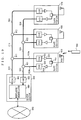
- A system for bi-directional optical communications between a master station (490) and a plurality of slave stations (590a, 590b, 590c), whereinthe master station and the slave stations are connected to each other via a single optical fiber,the slave stations are assigned different wavelengths of downstream optical signals transmitted from the master station to the slave stations,the slave stations are assigned different wavelength of upstream optical signals transmitted from the slave stations to the master station,the master station transmits the downstream optical signals to the respective slave stations via the single optical fiber, and the slave stations respectively transmit the upstream optical signals to the master station via the single optical fiber,the master station includes:each of the slave stations includes:a plurality of first electrical-optical converters (403a, 403b, 403c), provided correspondingly to the slave stations, each for converting an electrical signal to a downstream optical signal having a wavelength assigned to a corresponding slave station;a plurality of optical-electrical converters (404a, 404b, 404c) , provided correspondingly to the slave stations, each for converting an upstream optical signal supplied by a corresponding slave station to an electrical signal; anda wavelength multiplexer/demultiplexer (495) for wavelength-multiplexing the downstream optical signals supplied by the first electrical-optical converters and outputting a multiplexed signal to the single optical fiber, and for wavelength-demultiplexing the upstream optical signals transmitted through the single optical fibers and outputting optical signals correspondingly in wavelength to the first optical-electrical converters, anda second electric-optical converter (503a) for converting an electrical signal to an upstream optical signal having a wavelength assigned to the slave station;a second optical-electrical converter (504a) for converting the downstream optical signal to an electrical signal; andan optical add/drop unit (700a), provided between the single optical fiber, and the second electrical-optical converter and the second optical-electrical converter, for outputting the upstream optical signal supplied by the second electrical-optical converter to the single optical fiber and outputting only a downstream optical signal having a wavelength assigned to the slave station from out of the downstream optical signals transmitted through the single optical fiber to the second optical-electrical converter.
- The bi-directional optical transmission system according to claim 35, wherein
the optical add/drop unit is structured by connecting, in series, two wavelength combining/branching units (721, 722) each having three terminals. - The bi-directional optical transmission system according to claim 35, wherein
the optical add/drop unit (730) includes:a wavelength combiner (733) for combining the upstream optical signal output from the second electrical-optical converter (735) and the upstream optical signal transmitted through the single optical fiber; anda wavelength separator (734) for separating only an optical signal having a wavelength assigned to a corresponding slave station from a plurality of said downstream optical signals transmitted through the single optical fiber, and outputting the separated optical signal to the second optical-electrical converter (736),the wavelength combiner and the second electrical-optical converter is integrated as an optical transmission module (731), andthe wavelength separator and the second optical-electrical converter is integrated as an optical reception module (732). - The bi-directional optical transmission system according to claim 35, wherein
the optical add/drop unit (740) includes:a wavelength combining/branching unit (741) having three terminals; andan optical circulator (742) having first, second, and third terminals, the first terminal being connected to one of the three terminals of the wavelength combining/branching unit, for transmitting and receiving only an optical signal having a wavelength assigned to a corresponding slave station,the second terminal of the optical circulator is connected to the second electrical-optical converter and the third terminal of the optical circulator is connected to the second optical-electrical converter, andthe wavelength of the downstream optical signal and the wavelength of the upstream optical signal assigned to each of the slave stations are equal to each other. - The bi-directional optical transmission system according to claim 35, wherein
the optical add/drop unit (750) includes:a wavelength combining/branching unit (751) having three terminals; andan optical branching unit (752) having first, second, and third terminals, the first terminal being connected to one of the three terminals of the wavelength combining/branching unit, for transmitting and receiving only an optical signal having a wavelength assigned to a corresponding slave/station,the second terminal of the optical branching unit is connected to the second electrical-optical converter and the third terminal of the optical branching unit is connected to the second optical-electrical converter, andthe wavelength of the downstream optical signal and the wavelength of the upstream optical signal assigned to each of the slave stations are equal to each other. - The bi-directional optical transmission system according to claim 39, whereinthe optical add/drop unit further includesan optical isolator (753) placed between the second terminal of the optical branching unit and the second electrical-optical converter.
- The bi-directional optical transmission system according to claim 35, wherein
the electrical signals supplied to the first electrical-optical converter and the second electrical-optical converter are sub-carrier modulated signals. - The bi-directional optical transmission system according to claim 35, wherein
each of the slave stations further includesa wireless transmitter/receiver (501, 506, 507, 508) for wirelessly transmitting and receiving the upstream electrical signal supplied to the second electrical-optical converter and the downstream electrical signal output from the second optical-electrical converter. - The bi-directional optical transmission system according to claim 42, wherein
the upstream electrical signal and the downstream electrical signal are portable phone signals. - The bi-directional optical transmission system according to claim 35, wherein
a wavelength interval for each of the slave station is 20nm.
Priority Applications (1)
| Application Number | Priority Date | Filing Date | Title |
|---|---|---|---|
| EP05020226A EP1605614A1 (en) | 2002-02-26 | 2003-02-20 | Bi-directional optical transmission system, and master and slave stations used therefor |
Applications Claiming Priority (4)
| Application Number | Priority Date | Filing Date | Title |
|---|---|---|---|
| JP2002050046 | 2002-02-26 | ||
| JP2002050046 | 2002-02-26 | ||
| JP2002360829A JP2003324393A (en) | 2002-02-26 | 2002-12-12 | Bi-directional optical transmission system, and master and slave stations used therefor |
| JP2002360829 | 2002-12-12 |
Publications (2)
| Publication Number | Publication Date |
|---|---|
| EP1339179A2 true EP1339179A2 (en) | 2003-08-27 |
| EP1339179A3 EP1339179A3 (en) | 2004-12-22 |
Family
ID=27667563
Family Applications (2)
| Application Number | Title | Priority Date | Filing Date |
|---|---|---|---|
| EP05020226A Withdrawn EP1605614A1 (en) | 2002-02-26 | 2003-02-20 | Bi-directional optical transmission system, and master and slave stations used therefor |
| EP03003870A Withdrawn EP1339179A3 (en) | 2002-02-26 | 2003-02-20 | Bi-directional optical transmission system, and master and slave stations used therefor |
Family Applications Before (1)
| Application Number | Title | Priority Date | Filing Date |
|---|---|---|---|
| EP05020226A Withdrawn EP1605614A1 (en) | 2002-02-26 | 2003-02-20 | Bi-directional optical transmission system, and master and slave stations used therefor |
Country Status (4)
| Country | Link |
|---|---|
| US (1) | US20030161637A1 (en) |
| EP (2) | EP1605614A1 (en) |
| JP (1) | JP2003324393A (en) |
| CN (1) | CN1447539A (en) |
Cited By (9)
| Publication number | Priority date | Publication date | Assignee | Title |
|---|---|---|---|---|
| EP1605613A1 (en) * | 2004-06-10 | 2005-12-14 | Matsushita Electric Industrial Co., Ltd. | Optical signal transmission system and signal transmission method |
| WO2006051262A1 (en) * | 2004-11-15 | 2006-05-18 | Bae Systems Plc | Data communications system |
| EP1686715A1 (en) * | 2005-01-31 | 2006-08-02 | Fujitsu Ltd. | Optical network system and transmission apparatus |
| FR2896931A1 (en) * | 2006-01-30 | 2007-08-03 | Micro Module Sarl | Information e.g. video, transmission system for e.g. aircraft, has electronic transmission circuits and electronic reception circuits respectively connected to optical detectors and optical sources |
| EP2351261A1 (en) * | 2008-10-31 | 2011-08-03 | Hewlett-Packard Development Company, L.P. | Optical broadcast buses with shared optical interfaces |
| WO2011152831A1 (en) * | 2010-06-04 | 2011-12-08 | Ccs Technology, Inc. | Optical fiber -based distributed communications system and method employing wavelength division multiplexing (wdm) for enhanced upgradability |
| EP2515454A1 (en) * | 2011-04-21 | 2012-10-24 | Tyco Electronics Nederland B.V. | Remote electronic component, such as remote radio head, for a wireless communication system, remote electronic component array and external distributor unit |
| US20120269509A1 (en) * | 2011-04-21 | 2012-10-25 | Antonius Petrus Hultermans | Remote Electronic Component, Such As Remote Radio Head, For A Wireless Communication System, Remote Electronic Component Array And External Distributor Unit |
| FR3124282A1 (en) * | 2021-06-25 | 2022-12-23 | Orange | Optronic transceiver module |
Families Citing this family (110)
| Publication number | Priority date | Publication date | Assignee | Title |
|---|---|---|---|---|
| US7529215B2 (en) * | 2003-11-17 | 2009-05-05 | Telefonaktiebolaget Lm Ericsson (Publ) | Encapsulation of independent transmissions over internal interface of distributed radio base station |
| JP4473600B2 (en) * | 2004-02-24 | 2010-06-02 | 株式会社日立国際電気 | Optical transmission equipment |
| JP2006005615A (en) * | 2004-06-17 | 2006-01-05 | Eiden Kk | Single-frequency network digital terrestrial broadcasting system, synchronization system for single-frequency network, and transmitting device |
| US7548695B2 (en) * | 2004-10-19 | 2009-06-16 | Nextg Networks, Inc. | Wireless signal distribution system and method |
| KR100617839B1 (en) * | 2004-11-16 | 2006-08-28 | 삼성전자주식회사 | Optical network for bidirectional- wireless communication |
| JP4561335B2 (en) * | 2004-11-30 | 2010-10-13 | 住友電気工業株式会社 | Optical data link |
| JP4852260B2 (en) * | 2005-05-16 | 2012-01-11 | 三菱電機株式会社 | Single-core bidirectional wavelength division multiplexing transmission system |
| JP4414382B2 (en) * | 2005-08-16 | 2010-02-10 | 東京エレクトロンデバイス株式会社 | OPTICAL NETWORK SYSTEM, OPTICAL NETWORK DEVICE, AND OPTICAL NETWORK CONTROL METHOD |
| US8027299B2 (en) * | 2005-11-25 | 2011-09-27 | Gal Zuckerman | Hybrid system having multiple downlink channels and a single uplink channel |
| US7469196B2 (en) * | 2005-12-14 | 2008-12-23 | Advantest Corporation | Measuring a characteristic of a transfer circuit |
| WO2007131519A1 (en) * | 2006-05-12 | 2007-11-22 | Siemens Home And Office Communication Devices Gmbh & Co. Kg | Device for transmitting and receiving data and corresponding operating method |
| US8472767B2 (en) * | 2006-05-19 | 2013-06-25 | Corning Cable Systems Llc | Fiber optic cable and fiber optic cable assembly for wireless access |
| US20070292136A1 (en) * | 2006-06-16 | 2007-12-20 | Michael Sauer | Transponder for a radio-over-fiber optical fiber cable |
| US20080013957A1 (en) * | 2006-07-14 | 2008-01-17 | Tenvera, Inc. | Service Aggregation Gateway |
| US20080013909A1 (en) * | 2006-07-14 | 2008-01-17 | Tenvera, Inc. | Modular Optical Fiber Network Interface |
| US20080013956A1 (en) * | 2006-07-14 | 2008-01-17 | Tenvera, Inc. | Provisioning of Services Via an Optical Fiber Network |
| US20080013907A1 (en) * | 2006-07-14 | 2008-01-17 | Tenvera, Inc. | Optical Fiber Blowing Device and Method |
| US20080011990A1 (en) * | 2006-07-14 | 2008-01-17 | Tenvera, Inc. | Installation of Fiber Optic Cables |
| US20080013893A1 (en) * | 2006-07-14 | 2008-01-17 | Tenvera, Inc. | Optical Fiber Ferrule and Ferrule Receiver, and Method for Manufacturing the Same |
| US20080011514A1 (en) * | 2006-07-14 | 2008-01-17 | Tenvera, Inc. | Optical Fiber Distribution Apparatus and Method |
| US7787823B2 (en) | 2006-09-15 | 2010-08-31 | Corning Cable Systems Llc | Radio-over-fiber (RoF) optical fiber cable system with transponder diversity and RoF wireless picocellular system using same |
| US7848654B2 (en) | 2006-09-28 | 2010-12-07 | Corning Cable Systems Llc | Radio-over-fiber (RoF) wireless picocellular system with combined picocells |
| US8873585B2 (en) | 2006-12-19 | 2014-10-28 | Corning Optical Communications Wireless Ltd | Distributed antenna system for MIMO technologies |
| US8111998B2 (en) | 2007-02-06 | 2012-02-07 | Corning Cable Systems Llc | Transponder systems and methods for radio-over-fiber (RoF) wireless picocellular systems |
| US20100054746A1 (en) * | 2007-07-24 | 2010-03-04 | Eric Raymond Logan | Multi-port accumulator for radio-over-fiber (RoF) wireless picocellular systems |
| US8175459B2 (en) | 2007-10-12 | 2012-05-08 | Corning Cable Systems Llc | Hybrid wireless/wired RoF transponder and hybrid RoF communication system using same |
| WO2009081376A2 (en) | 2007-12-20 | 2009-07-02 | Mobileaccess Networks Ltd. | Extending outdoor location based services and applications into enclosed areas |
| DE102008013245A1 (en) * | 2008-03-08 | 2009-09-17 | Andrew Wireless Systems Gmbh | Repeater and method for operating such a repeater |
| CA2731426C (en) * | 2008-07-30 | 2018-04-17 | Micro Motion, Inc. | Data translation system and method |
| US9673904B2 (en) | 2009-02-03 | 2017-06-06 | Corning Optical Communications LLC | Optical fiber-based distributed antenna systems, components, and related methods for calibration thereof |
| EP2394379B1 (en) | 2009-02-03 | 2016-12-28 | Corning Optical Communications LLC | Optical fiber-based distributed antenna systems, components, and related methods for calibration thereof |
| AU2010210766A1 (en) | 2009-02-03 | 2011-09-15 | Corning Cable Systems Llc | Optical fiber-based distributed antenna systems, components, and related methods for monitoring and configuring thereof |
| TWI385958B (en) * | 2009-03-20 | 2013-02-11 | Ind Tech Res Inst | System for providing wireless communication over a passive optical network (pon) |
| JP2010245987A (en) * | 2009-04-09 | 2010-10-28 | Nippon Telegr & Teleph Corp <Ntt> | Optical/radio access system |
| US9590733B2 (en) * | 2009-07-24 | 2017-03-07 | Corning Optical Communications LLC | Location tracking using fiber optic array cables and related systems and methods |
| US8548330B2 (en) | 2009-07-31 | 2013-10-01 | Corning Cable Systems Llc | Sectorization in distributed antenna systems, and related components and methods |
| US8280259B2 (en) | 2009-11-13 | 2012-10-02 | Corning Cable Systems Llc | Radio-over-fiber (RoF) system for protocol-independent wired and/or wireless communication |
| US8275265B2 (en) | 2010-02-15 | 2012-09-25 | Corning Cable Systems Llc | Dynamic cell bonding (DCB) for radio-over-fiber (RoF)-based networks and communication systems and related methods |
| US20110268446A1 (en) | 2010-05-02 | 2011-11-03 | Cune William P | Providing digital data services in optical fiber-based distributed radio frequency (rf) communications systems, and related components and methods |
| US9525488B2 (en) | 2010-05-02 | 2016-12-20 | Corning Optical Communications LLC | Digital data services and/or power distribution in optical fiber-based distributed communications systems providing digital data and radio frequency (RF) communications services, and related components and methods |
| US20130089332A1 (en) * | 2010-06-04 | 2013-04-11 | Michael Sauer | Optical fiber-based distributed communications components, systems, and methods employing wavelength division multiplexing (wdm) for enhanced upgradability |
| WO2012024247A1 (en) | 2010-08-16 | 2012-02-23 | Corning Cable Systems Llc | Remote antenna clusters and related systems, components, and methods supporting digital data signal propagation between remote antenna units |
| US9252874B2 (en) | 2010-10-13 | 2016-02-02 | Ccs Technology, Inc | Power management for remote antenna units in distributed antenna systems |
| US8452187B2 (en) * | 2010-12-02 | 2013-05-28 | Eastern Optx Inc. | Bi-directional, compact, multi-path and free space channel replicator |
| TWI416895B (en) * | 2010-12-07 | 2013-11-21 | Ind Tech Res Inst | A signal transmitting method for peer-to-peer optical networks and system using the same |
| CN203504582U (en) | 2011-02-21 | 2014-03-26 | 康宁光缆系统有限责任公司 | Distributed antenna system and power supply apparatus for distributing electric power thereof |
| CN103548290B (en) | 2011-04-29 | 2016-08-31 | 康宁光缆系统有限责任公司 | Judge the communication propagation delays in distributing antenna system and associated component, System and method for |
| CN103609146B (en) | 2011-04-29 | 2017-05-31 | 康宁光缆系统有限责任公司 | For increasing the radio frequency in distributing antenna system(RF)The system of power, method and apparatus |
| US9031409B2 (en) * | 2011-04-29 | 2015-05-12 | Arris Technology, Inc. | System and method for avoiding upstream interference in RF-over-glass network |
| US9715001B2 (en) * | 2011-06-13 | 2017-07-25 | Commscope Technologies Llc | Mobile location in a remote radio head environment |
| US8734026B2 (en) * | 2011-08-19 | 2014-05-27 | Teledyne Instruments, Inc. | Subsea electro-optical connector unit for electro-optical ethernet transmission system |
| US8606110B2 (en) * | 2012-01-08 | 2013-12-10 | Optiway Ltd. | Optical distributed antenna system |
| US20130202308A1 (en) * | 2012-02-08 | 2013-08-08 | Harris Corporation, Corporation Of The State Of Delaware | Phased antenna array including a plurality of electro-optical circuits having an optical source with an opto-electronic oscillator and associated methods |
| WO2013148986A1 (en) | 2012-03-30 | 2013-10-03 | Corning Cable Systems Llc | Reducing location-dependent interference in distributed antenna systems operating in multiple-input, multiple-output (mimo) configuration, and related components, systems, and methods |
| WO2013162988A1 (en) | 2012-04-25 | 2013-10-31 | Corning Cable Systems Llc | Distributed antenna system architectures |
| WO2014024192A1 (en) | 2012-08-07 | 2014-02-13 | Corning Mobile Access Ltd. | Distribution of time-division multiplexed (tdm) management services in a distributed antenna system, and related components, systems, and methods |
| US9455784B2 (en) | 2012-10-31 | 2016-09-27 | Corning Optical Communications Wireless Ltd | Deployable wireless infrastructures and methods of deploying wireless infrastructures |
| WO2014085115A1 (en) | 2012-11-29 | 2014-06-05 | Corning Cable Systems Llc | HYBRID INTRA-CELL / INTER-CELL REMOTE UNIT ANTENNA BONDING IN MULTIPLE-INPUT, MULTIPLE-OUTPUT (MIMO) DISTRIBUTED ANTENNA SYSTEMS (DASs) |
| US9647758B2 (en) | 2012-11-30 | 2017-05-09 | Corning Optical Communications Wireless Ltd | Cabling connectivity monitoring and verification |
| EP3008515A1 (en) | 2013-06-12 | 2016-04-20 | Corning Optical Communications Wireless, Ltd | Voltage controlled optical directional coupler |
| EP3008828B1 (en) | 2013-06-12 | 2017-08-09 | Corning Optical Communications Wireless Ltd. | Time-division duplexing (tdd) in distributed communications systems, including distributed antenna systems (dass) |
| US9247543B2 (en) | 2013-07-23 | 2016-01-26 | Corning Optical Communications Wireless Ltd | Monitoring non-supported wireless spectrum within coverage areas of distributed antenna systems (DASs) |
| US9661781B2 (en) | 2013-07-31 | 2017-05-23 | Corning Optical Communications Wireless Ltd | Remote units for distributed communication systems and related installation methods and apparatuses |
| US9385810B2 (en) | 2013-09-30 | 2016-07-05 | Corning Optical Communications Wireless Ltd | Connection mapping in distributed communication systems |
| CN104635306A (en) * | 2013-11-08 | 2015-05-20 | 昂纳信息技术(深圳)有限公司 | Multi-wavelength optical transceiver module of single optical fiber coupling |
| US9178635B2 (en) | 2014-01-03 | 2015-11-03 | Corning Optical Communications Wireless Ltd | Separation of communication signal sub-bands in distributed antenna systems (DASs) to reduce interference |
| US9775123B2 (en) | 2014-03-28 | 2017-09-26 | Corning Optical Communications Wireless Ltd. | Individualized gain control of uplink paths in remote units in a distributed antenna system (DAS) based on individual remote unit contribution to combined uplink power |
| JP6899856B2 (en) * | 2014-04-29 | 2021-07-07 | 華為技術有限公司Huawei Technologies Co.,Ltd. | Wireless communication system and wireless radio frequency device |
| ES2690389T3 (en) | 2014-04-29 | 2018-11-20 | Huawei Technologies Co. Ltd. | Wireless communications system and radio frequency device |
| US9357551B2 (en) | 2014-05-30 | 2016-05-31 | Corning Optical Communications Wireless Ltd | Systems and methods for simultaneous sampling of serial digital data streams from multiple analog-to-digital converters (ADCS), including in distributed antenna systems |
| US9525472B2 (en) | 2014-07-30 | 2016-12-20 | Corning Incorporated | Reducing location-dependent destructive interference in distributed antenna systems (DASS) operating in multiple-input, multiple-output (MIMO) configuration, and related components, systems, and methods |
| US9730228B2 (en) | 2014-08-29 | 2017-08-08 | Corning Optical Communications Wireless Ltd | Individualized gain control of remote uplink band paths in a remote unit in a distributed antenna system (DAS), based on combined uplink power level in the remote unit |
| GB2530069A (en) * | 2014-09-12 | 2016-03-16 | Bae Systems Plc | Signal processing apparatus |
| US9602210B2 (en) | 2014-09-24 | 2017-03-21 | Corning Optical Communications Wireless Ltd | Flexible head-end chassis supporting automatic identification and interconnection of radio interface modules and optical interface modules in an optical fiber-based distributed antenna system (DAS) |
| US9420542B2 (en) | 2014-09-25 | 2016-08-16 | Corning Optical Communications Wireless Ltd | System-wide uplink band gain control in a distributed antenna system (DAS), based on per band gain control of remote uplink paths in remote units |
| US10659163B2 (en) | 2014-09-25 | 2020-05-19 | Corning Optical Communications LLC | Supporting analog remote antenna units (RAUs) in digital distributed antenna systems (DASs) using analog RAU digital adaptors |
| US9917648B2 (en) * | 2014-10-01 | 2018-03-13 | Arris Enterprises Llc | Upstream interference eliminating transmission of digital baseband signal in an optical network |
| WO2016071902A1 (en) | 2014-11-03 | 2016-05-12 | Corning Optical Communications Wireless Ltd. | Multi-band monopole planar antennas configured to facilitate improved radio frequency (rf) isolation in multiple-input multiple-output (mimo) antenna arrangement |
| WO2016075696A1 (en) | 2014-11-13 | 2016-05-19 | Corning Optical Communications Wireless Ltd. | Analog distributed antenna systems (dass) supporting distribution of digital communications signals interfaced from a digital signal source and analog radio frequency (rf) communications signals |
| US9729267B2 (en) | 2014-12-11 | 2017-08-08 | Corning Optical Communications Wireless Ltd | Multiplexing two separate optical links with the same wavelength using asymmetric combining and splitting |
| WO2016098111A1 (en) | 2014-12-18 | 2016-06-23 | Corning Optical Communications Wireless Ltd. | Digital- analog interface modules (da!ms) for flexibly.distributing digital and/or analog communications signals in wide-area analog distributed antenna systems (dass) |
| WO2016098109A1 (en) | 2014-12-18 | 2016-06-23 | Corning Optical Communications Wireless Ltd. | Digital interface modules (dims) for flexibly distributing digital and/or analog communications signals in wide-area analog distributed antenna systems (dass) |
| US20160249365A1 (en) | 2015-02-19 | 2016-08-25 | Corning Optical Communications Wireless Ltd. | Offsetting unwanted downlink interference signals in an uplink path in a distributed antenna system (das) |
| US9681313B2 (en) | 2015-04-15 | 2017-06-13 | Corning Optical Communications Wireless Ltd | Optimizing remote antenna unit performance using an alternative data channel |
| US9948349B2 (en) | 2015-07-17 | 2018-04-17 | Corning Optical Communications Wireless Ltd | IOT automation and data collection system |
| US9603155B2 (en) * | 2015-07-31 | 2017-03-21 | Corning Optical Communications Wireless Ltd | Reducing leaked downlink interference signals in a remote unit uplink path(s) in a distributed antenna system (DAS) |
| US11637612B2 (en) | 2015-08-25 | 2023-04-25 | Cellium Technologies, Ltd. | Macro-diversity using hybrid transmissions via twisted pairs |
| US10560214B2 (en) | 2015-09-28 | 2020-02-11 | Corning Optical Communications LLC | Downlink and uplink communication path switching in a time-division duplex (TDD) distributed antenna system (DAS) |
| US10110306B2 (en) | 2015-12-13 | 2018-10-23 | GenXComm, Inc. | Interference cancellation methods and apparatus |
| US10397190B2 (en) * | 2016-02-05 | 2019-08-27 | Huawei Technologies Co., Ltd. | System and method for generating an obfuscated optical signal |
| US10236924B2 (en) | 2016-03-31 | 2019-03-19 | Corning Optical Communications Wireless Ltd | Reducing out-of-channel noise in a wireless distribution system (WDS) |
| US10257746B2 (en) * | 2016-07-16 | 2019-04-09 | GenXComm, Inc. | Interference cancellation methods and apparatus |
| US9894612B1 (en) | 2016-11-03 | 2018-02-13 | Corning Optical Communications Wireless Ltd | Reducing power consumption in a remote unit of a wireless distribution system (WDS) for intermodulation product suppression |
| JP6875703B2 (en) * | 2018-03-05 | 2021-05-26 | 日本電信電話株式会社 | Communication network and wraparound signal removal method |
| JP2020068485A (en) * | 2018-10-25 | 2020-04-30 | 日本放送協会 | Relay device |
| WO2020121833A1 (en) | 2018-12-11 | 2020-06-18 | 日東電工株式会社 | Optical transmission system and electro-optical conversion device |
| JP6812490B2 (en) * | 2018-12-11 | 2021-01-13 | 日東電工株式会社 | Optical transmission system and electro-optical conversion device |
| US11150409B2 (en) | 2018-12-27 | 2021-10-19 | GenXComm, Inc. | Saw assisted facet etch dicing |
| JP7318349B2 (en) * | 2019-06-21 | 2023-08-01 | 日本電信電話株式会社 | communication network system |
| US10727945B1 (en) | 2019-07-15 | 2020-07-28 | GenXComm, Inc. | Efficiently combining multiple taps of an optical filter |
| US20220286221A1 (en) * | 2019-09-06 | 2022-09-08 | Telefonaktiebolaget Lm Ericsson (Publ) | Optical Node and Optical Transceiver for Auto Tuning of Operational Wavelength |
| US11215755B2 (en) | 2019-09-19 | 2022-01-04 | GenXComm, Inc. | Low loss, polarization-independent, large bandwidth mode converter for edge coupling |
| US11539394B2 (en) | 2019-10-29 | 2022-12-27 | GenXComm, Inc. | Self-interference mitigation in in-band full-duplex communication systems |
| CN111416658B (en) * | 2020-03-27 | 2021-04-09 | 中国科学院声学研究所 | Submarine observation network trunk line optical signal transmission device and transmission method |
| KR102415629B1 (en) * | 2020-04-22 | 2022-07-01 | 한국전자통신연구원 | System and method for optical sending and receiving |
| US11796737B2 (en) | 2020-08-10 | 2023-10-24 | GenXComm, Inc. | Co-manufacturing of silicon-on-insulator waveguides and silicon nitride waveguides for hybrid photonic integrated circuits |
| US11611817B2 (en) * | 2020-09-14 | 2023-03-21 | Corning Research & Development Corporation | Time division multiplexing and wavelength division multiplexing hybrid distribution component and systems |
| CA3234722A1 (en) | 2021-10-25 | 2023-05-04 | Farzad Mokhtari-Koushyar | Hybrid photonic integrated circuits for ultra-low phase noise signal generators |
| WO2023148874A1 (en) * | 2022-02-03 | 2023-08-10 | 日本電信電話株式会社 | Optical communication system, aggregation station, and communication method |
| WO2023148880A1 (en) * | 2022-02-03 | 2023-08-10 | 日本電信電話株式会社 | Communication system, dispatch station, communication method, and communication system creation method |
Citations (12)
| Publication number | Priority date | Publication date | Assignee | Title |
|---|---|---|---|---|
| US4726010A (en) * | 1985-02-28 | 1988-02-16 | Standard Elektrik Lorenz Ag | Optical communication system in the subscriber loop |
| EP0368673A1 (en) * | 1988-11-11 | 1990-05-16 | BRITISH TELECOMMUNICATIONS public limited company | Communications system |
| EP0391597A2 (en) * | 1989-04-04 | 1990-10-10 | AT&T Corp. | Optical fiber microcellular mobile radio |
| EP0794629A2 (en) * | 1996-03-04 | 1997-09-10 | Kokusai Denshin Denwa Kabushiki Kaisha | Optical add-drop multiplexer |
| EP0843380A2 (en) * | 1996-11-13 | 1998-05-20 | Sumitomo Electric Industries, Ltd. | Wireless mobile communication system |
| EP1009119A2 (en) * | 1998-12-10 | 2000-06-14 | Nortel Networks Corporation | Integration of Optical Add Drop Multiplexing filters |
| EP1089478A2 (en) * | 1999-10-01 | 2001-04-04 | Matsushita Electric Industrial Co., Ltd. | FM signal converter, FM signal optical transmitter and FM signal optical receiver |
| US6295148B1 (en) * | 1997-10-21 | 2001-09-25 | Antec Corporation | Optical network for transmitting two-way multicast signals |
| WO2001084760A1 (en) * | 2000-04-28 | 2001-11-08 | Lgc Wireless, Inc. | A cellular communications system with centralized capacity resources using dwdm fiber optic backbone |
| EP1173034A1 (en) * | 2000-07-10 | 2002-01-16 | Samsung Electronics Co., Ltd. | Mobile communication network system using digital optical link |
| EP1179895A1 (en) * | 2000-03-21 | 2002-02-13 | Matsushita Electric Industrial Co., Ltd. | Array antenna base station apparatus |
| WO2002015439A1 (en) * | 2000-08-18 | 2002-02-21 | Allgon Ab | Communication system with fiber optical link |
Family Cites Families (9)
| Publication number | Priority date | Publication date | Assignee | Title |
|---|---|---|---|---|
| US5682256A (en) * | 1988-11-11 | 1997-10-28 | British Telecommunications Public Limited Company | Communications system |
| JPH0818514A (en) * | 1994-06-29 | 1996-01-19 | Fujitsu Ltd | Same wavelength two-way transmission system for optical subscriber |
| US5633741A (en) * | 1995-02-23 | 1997-05-27 | Lucent Technologies Inc. | Multichannel optical fiber communications |
| US5936754A (en) * | 1996-12-02 | 1999-08-10 | At&T Corp. | Transmission of CDMA signals over an analog optical link |
| JP3482088B2 (en) * | 1996-12-05 | 2003-12-22 | 松下電器産業株式会社 | Frequency modulation device |
| US5969836A (en) * | 1997-12-12 | 1999-10-19 | Alcatel Usa Sourcing, L.P. | Method and apparatus for simultaneous transmission of digital telephony and analog video over a single optic fiber using wave division multiplexing |
| US6211978B1 (en) * | 1999-02-10 | 2001-04-03 | Anacom Systems, Inc. | Multi-channel wave division multiplexer system |
| US6480315B1 (en) * | 1999-08-06 | 2002-11-12 | Nortel Networks Limited | Method and apparatus for SNR measurement |
| US6885821B2 (en) * | 2001-02-27 | 2005-04-26 | Avanex Corporation | Full-duplex optical add/drop communications system utilizing central light sources |
-
2002
- 2002-12-12 JP JP2002360829A patent/JP2003324393A/en active Pending
-
2003
- 2003-02-20 EP EP05020226A patent/EP1605614A1/en not_active Withdrawn
- 2003-02-20 EP EP03003870A patent/EP1339179A3/en not_active Withdrawn
- 2003-02-25 US US10/372,198 patent/US20030161637A1/en not_active Abandoned
- 2003-02-26 CN CN03121794A patent/CN1447539A/en active Pending
Patent Citations (12)
| Publication number | Priority date | Publication date | Assignee | Title |
|---|---|---|---|---|
| US4726010A (en) * | 1985-02-28 | 1988-02-16 | Standard Elektrik Lorenz Ag | Optical communication system in the subscriber loop |
| EP0368673A1 (en) * | 1988-11-11 | 1990-05-16 | BRITISH TELECOMMUNICATIONS public limited company | Communications system |
| EP0391597A2 (en) * | 1989-04-04 | 1990-10-10 | AT&T Corp. | Optical fiber microcellular mobile radio |
| EP0794629A2 (en) * | 1996-03-04 | 1997-09-10 | Kokusai Denshin Denwa Kabushiki Kaisha | Optical add-drop multiplexer |
| EP0843380A2 (en) * | 1996-11-13 | 1998-05-20 | Sumitomo Electric Industries, Ltd. | Wireless mobile communication system |
| US6295148B1 (en) * | 1997-10-21 | 2001-09-25 | Antec Corporation | Optical network for transmitting two-way multicast signals |
| EP1009119A2 (en) * | 1998-12-10 | 2000-06-14 | Nortel Networks Corporation | Integration of Optical Add Drop Multiplexing filters |
| EP1089478A2 (en) * | 1999-10-01 | 2001-04-04 | Matsushita Electric Industrial Co., Ltd. | FM signal converter, FM signal optical transmitter and FM signal optical receiver |
| EP1179895A1 (en) * | 2000-03-21 | 2002-02-13 | Matsushita Electric Industrial Co., Ltd. | Array antenna base station apparatus |
| WO2001084760A1 (en) * | 2000-04-28 | 2001-11-08 | Lgc Wireless, Inc. | A cellular communications system with centralized capacity resources using dwdm fiber optic backbone |
| EP1173034A1 (en) * | 2000-07-10 | 2002-01-16 | Samsung Electronics Co., Ltd. | Mobile communication network system using digital optical link |
| WO2002015439A1 (en) * | 2000-08-18 | 2002-02-21 | Allgon Ab | Communication system with fiber optical link |
Cited By (16)
| Publication number | Priority date | Publication date | Assignee | Title |
|---|---|---|---|---|
| EP1605613A1 (en) * | 2004-06-10 | 2005-12-14 | Matsushita Electric Industrial Co., Ltd. | Optical signal transmission system and signal transmission method |
| US8055136B2 (en) | 2004-11-15 | 2011-11-08 | Bae Systems Plc | Data communications system |
| WO2006051262A1 (en) * | 2004-11-15 | 2006-05-18 | Bae Systems Plc | Data communications system |
| EP1686715A1 (en) * | 2005-01-31 | 2006-08-02 | Fujitsu Ltd. | Optical network system and transmission apparatus |
| US7826744B2 (en) | 2005-01-31 | 2010-11-02 | Fujitsu Limited | Optical network system and transmission apparatus |
| FR2896931A1 (en) * | 2006-01-30 | 2007-08-03 | Micro Module Sarl | Information e.g. video, transmission system for e.g. aircraft, has electronic transmission circuits and electronic reception circuits respectively connected to optical detectors and optical sources |
| US8687961B2 (en) | 2008-10-31 | 2014-04-01 | Hewlett-Packard Development Company, L.P. | Optical broadcast with buses with shared optical interfaces |
| CN102204124A (en) * | 2008-10-31 | 2011-09-28 | 惠普开发有限公司 | Optical broadcast buses with shared optical interfaces |
| EP2351261A4 (en) * | 2008-10-31 | 2013-04-17 | Hewlett Packard Development Co | Optical broadcast buses with shared optical interfaces |
| EP2351261A1 (en) * | 2008-10-31 | 2011-08-03 | Hewlett-Packard Development Company, L.P. | Optical broadcast buses with shared optical interfaces |
| CN102204124B (en) * | 2008-10-31 | 2015-07-01 | 惠普开发有限公司 | Optical broadcast buses with shared optical interfaces |
| WO2011152831A1 (en) * | 2010-06-04 | 2011-12-08 | Ccs Technology, Inc. | Optical fiber -based distributed communications system and method employing wavelength division multiplexing (wdm) for enhanced upgradability |
| EP2515454A1 (en) * | 2011-04-21 | 2012-10-24 | Tyco Electronics Nederland B.V. | Remote electronic component, such as remote radio head, for a wireless communication system, remote electronic component array and external distributor unit |
| US20120269509A1 (en) * | 2011-04-21 | 2012-10-25 | Antonius Petrus Hultermans | Remote Electronic Component, Such As Remote Radio Head, For A Wireless Communication System, Remote Electronic Component Array And External Distributor Unit |
| FR3124282A1 (en) * | 2021-06-25 | 2022-12-23 | Orange | Optronic transceiver module |
| EP4109158A1 (en) * | 2021-06-25 | 2022-12-28 | Orange | Optoelectronic transmitter-receiver module |
Also Published As
| Publication number | Publication date |
|---|---|
| EP1605614A1 (en) | 2005-12-14 |
| EP1339179A3 (en) | 2004-12-22 |
| JP2003324393A (en) | 2003-11-14 |
| US20030161637A1 (en) | 2003-08-28 |
| CN1447539A (en) | 2003-10-08 |
Similar Documents
| Publication | Publication Date | Title |
|---|---|---|
| EP1339179A2 (en) | Bi-directional optical transmission system, and master and slave stations used therefor | |
| KR100663466B1 (en) | Remote access unit and radio-over-fiber network using the same | |
| EP2180614B1 (en) | Optical line terminal, passive optical network and radio frequency signal transmission method | |
| CN102710361B (en) | A kind of distributed base station signal transmission system and communication system | |
| US5995254A (en) | Wavelength division multiplexing light transmitting system | |
| WO2010093195A9 (en) | Low-noise optical signal transmitter with low-noise multi-wavelength light source, broadcast signal transmitter using low-noise multi-wavelength light source, and optical network with the same | |
| JPH08167877A (en) | Optical network and relay node | |
| US20100021164A1 (en) | Wdm pon rf/video broadcast overlay | |
| KR100968926B1 (en) | Optical repeating system for multiple band at mobile telecommunication network | |
| CN103314542A (en) | Method and arrangement for receiving an optical input signal and transmittning an optical output signal | |
| KR100960110B1 (en) | Optical Backhaul Network for Wireless Broadband Service | |
| JPH0448832A (en) | Optical link radio communication system | |
| KR100619372B1 (en) | Optical transiver system for a combined wire and wireless service | |
| JPH06311116A (en) | Bidirectional optical fiber transmission system | |
| EP1605613B1 (en) | Optical signal transmission system and signal transmission method | |
| JPH07183871A (en) | Wavelength multiplexed optical communication system | |
| JP3568145B2 (en) | High frequency optical fiber transmission system using optical wavelength division multiplexing. | |
| Nirmalathas et al. | Millimeter-wave fiber-wireless access systems incorporating wavelength division multiplexing | |
| KR20000007806A (en) | Transmission system in optical switching system and methode thereof | |
| JP2013090217A (en) | Radio base station | |
| JPH07112182B2 (en) | Secret communication optical communication system in bidirectional optical transmission system | |
| JP3258038B2 (en) | Optical communication system | |
| KR20100107906A (en) | Analog optical repeater system of double wavelength division multiplexing type | |
| KR100619355B1 (en) | Multi-drop optical repeater system for the wireless communication systems | |
| JP3535937B2 (en) | Optical transmission system |
Legal Events
| Date | Code | Title | Description |
|---|---|---|---|
| PUAI | Public reference made under article 153(3) epc to a published international application that has entered the european phase |
Free format text: ORIGINAL CODE: 0009012 |
|
| AK | Designated contracting states |
Designated state(s): AT BE BG CH CY CZ DE DK EE ES FI FR GB GR HU IE IT LI LU MC NL PT SE SI SK TR |
|
| AX | Request for extension of the european patent |
Extension state: AL LT LV MK RO |
|
| RIC1 | Information provided on ipc code assigned before grant |
Ipc: 7H 04Q 7/30 B Ipc: 7H 04J 14/02 B Ipc: 7H 04B 10/12 A |
|
| PUAL | Search report despatched |
Free format text: ORIGINAL CODE: 0009013 |
|
| RIC1 | Information provided on ipc code assigned before grant |
Ipc: 7G 02B 6/34 B Ipc: 7H 04B 10/158 B Ipc: 7H 04B 10/155 B Ipc: 7H 04Q 7/30 B Ipc: 7H 04J 14/02 B Ipc: 7H 04B 10/12 A |
|
| AK | Designated contracting states |
Kind code of ref document: A3 Designated state(s): AT BE BG CH CY CZ DE DK EE ES FI FR GB GR HU IE IT LI LU MC NL PT SE SI SK TR |
|
| AX | Request for extension of the european patent |
Extension state: AL LT LV MK RO |
|
| 17P | Request for examination filed |
Effective date: 20050315 |
|
| 17Q | First examination report despatched |
Effective date: 20050504 |
|
| AKX | Designation fees paid |
Designated state(s): DE ES FR GB IT |
|
| STAA | Information on the status of an ep patent application or granted ep patent |
Free format text: STATUS: THE APPLICATION IS DEEMED TO BE WITHDRAWN |
|
| 18D | Application deemed to be withdrawn |
Effective date: 20060125 |