EP1338893B1 - Applicator of a fluid sample on a substrate - Google Patents
Applicator of a fluid sample on a substrate Download PDFInfo
- Publication number
- EP1338893B1 EP1338893B1 EP03003117A EP03003117A EP1338893B1 EP 1338893 B1 EP1338893 B1 EP 1338893B1 EP 03003117 A EP03003117 A EP 03003117A EP 03003117 A EP03003117 A EP 03003117A EP 1338893 B1 EP1338893 B1 EP 1338893B1
- Authority
- EP
- European Patent Office
- Prior art keywords
- blade
- applicator
- fluid sample
- drain
- substrate according
- Prior art date
- Legal status (The legal status is an assumption and is not a legal conclusion. Google has not performed a legal analysis and makes no representation as to the accuracy of the status listed.)
- Expired - Lifetime
Links
- 239000012530 fluid Substances 0.000 title claims abstract description 69
- 239000000758 substrate Substances 0.000 title claims abstract description 34
- 230000004888 barrier function Effects 0.000 claims abstract description 11
- 230000014759 maintenance of location Effects 0.000 claims abstract description 11
- 238000001962 electrophoresis Methods 0.000 claims description 7
- 229910001220 stainless steel Inorganic materials 0.000 claims description 2
- 239000010935 stainless steel Substances 0.000 claims description 2
- 230000005499 meniscus Effects 0.000 description 3
- 238000005070 sampling Methods 0.000 description 3
- 238000000605 extraction Methods 0.000 description 2
- 238000010899 nucleation Methods 0.000 description 2
- 238000004026 adhesive bonding Methods 0.000 description 1
- 238000004458 analytical method Methods 0.000 description 1
- 238000003780 insertion Methods 0.000 description 1
- 230000037431 insertion Effects 0.000 description 1
- 230000035515 penetration Effects 0.000 description 1
- 239000000126 substance Substances 0.000 description 1
Images


Classifications
-
- G—PHYSICS
- G01—MEASURING; TESTING
- G01N—INVESTIGATING OR ANALYSING MATERIALS BY DETERMINING THEIR CHEMICAL OR PHYSICAL PROPERTIES
- G01N27/00—Investigating or analysing materials by the use of electric, electrochemical, or magnetic means
- G01N27/26—Investigating or analysing materials by the use of electric, electrochemical, or magnetic means by investigating electrochemical variables; by using electrolysis or electrophoresis
- G01N27/416—Systems
- G01N27/447—Systems using electrophoresis
- G01N27/44704—Details; Accessories
- G01N27/44743—Introducing samples
Definitions
- the present invention refers to an apparatus for applying a fluid sample on a substrate, to be preferably used in the medical and chemical field to carry out analyses of a fluid sample with diagnostic scope, preferably for the electro-phoretic test of the fluid sample.
- the result of the electro-phoretic analysis of a fluid sample can be influenced by some factors like the shape, the volume, the amount and the positioning of the fluid sample on the substrate.
- each blade of the applicator takes the fluid sample adhered on its portion of surface comprised between the tip of the blade and the aperture of the blade.
- the amount taken of the fluid sample is not exactly defined when the applicator is dipped in the taking tray at such a depth that the barrier made on the blades is exceeded, because in such a case the amount of the fluid sample adhered to the blades over the barrier cannot be foreseen.
- the amount of fluid sample taken in such applicator can not be exactly defined also because of the fact that the fluid sample in the taking tray can make a meniscus that can prevent the tip of the blades from getting uniformly wet.
- the trays commonly used for such an applicator are equipped with narrow rectangular marks of housing of the rectangular blades of the applicator where the fluid to be sampled makes a meniscus.
- Such an applicator can prevent a complete seeding of the fluid sample taken on the substrate.
- a portion of the fluid sample present on the tip of the blades can be pushed towards the surface of the substrate by the action of the edges of the incision of the substrate and so can stay adhered to the blades of the applicator even after the extraction of the applicator from the substrate.
- a scope of the present invention is supplying an applicator able to deposit on a substrate an always exactly defined amount of fluid sample.
- Further scope of the present invention is to provide an applicator of a fluid sample on a substrate able to make a linear bidimensional deposit of the fluid sample on a substrate.
- an applicator of a fluid sample on a substrate comprising at least one and preferably more applying blades of substantially rectangular shape in its turn defining a body of the blade, a tip of the blade and two facing side edges of the blade, characterised in that each blade comprises:
- the drain of the blades of the applicator exactly marks the limits of an area of the blades of the applicator that is provided for the retention of a fluid sample.
- the drain of the blades of the applicator avoids an appreciable reascending of fluid by capillarity over the portion of retention of the fluid sample.
- the drain of the blades of the applicator avoids anyway every further taking of fluid even in case the blades of the applicator are dipped into the taking tray for a length that goes beyond such an area of retention of the fluid sample.
- the sampled fluid is that which trickles by capillarity into the aperture or apertures of the portion of the blades of the applicator of retention of the fluid sample.
- the fluid kept back in the retention portion of the blades of the applicator is totally transferred, without any difficulty, on the substrate determining a linear mark of the fluid sample on the substrate.
- the fluid kept back in the aperture or apertures of the retention portion of the blades of the applicator does not meet, during the insertion of the applicator on the substrate, the resistance from the edges of the incisions of the substrate made from the tips of the blades of the applicator, but, on the contrary, it uses, during the extraction of the applicator from the substrate, the resistance given from the edges of the incisions of the substrate made from the tips of the blades of the applicator for keeping the fluid on the substrate.
- a multi-blades applicator 1 for sampling a fluid to be analyzed in electro-phoretic mode is shown, with reference to figures 1 and 2, comprising a laminar longitudinal body 3 of the applicator 1, and a frame 5 for the support of the body 3 of the applicator 1 having the thickness of some millimetres and an essentially rectangular shape with longitudinal axis parallel to that of the body 3 of the applicator 1.
- the body 3 of the applicator is fixed to the frame 5 by gluing or, as illustrated, by means of a series of buttons 7 of the frame 5 pressure-fitted in the respective holes 9 of the body 3 of the applicator 1.
- the body of the applicator 3 is preferably made of stainless steel while the frame 5 can also be made of plastic.
- the edge of the part of the body 3 of the applicator 1 jutting out from the longitudinal side of the support frame 5 is shaped with a series of identical rectangular applying blades 11 longitudinally aligned.
- Each applying blade 11 comprises in correspondence of a portion of inner blade a drain 13 substantially rectangular longitudinally stretching between the facing side edges 15 and 17 of the blade 11 at a fixed distance from the tip 19 of the blade 11, which drain 13 defines a physical barrier for the fluid to be sampled.
- Each applying blade 11 further comprises in a position put between the tip 19 of the blade 11 and the drain 13 of the blade 11 a longitudinal calibrated aperture 21 for the retention of a fluid sample.
- the drain 13 of the blade 11 and the aperture 21 of the blade 11 are limited by facing side edges 23 and 25 having calibrated width, so as the width of the longitudinal edge 27 which separates the drain 13 of the blade 11 from the aperture 21 of the blade 11 and the width of the longitudinal edge 29 which separates the tip 19 of the blade 11 from the aperture 21 of the blade 11 are also calibrated.
- the size preferred for the applicator is as follows.
- Each blade 11 has a longitudinal size equal to 4.5 mm and height equal to 4 mm
- the drain 13 of each blade 11 has height equal to 2 mm
- the aperture 21 of each blade has height equal to 0.25 mm and preferably comprised between 0.2 and 0.3 mm
- the facing side edges 23 and 25 of each blade 11 have a width equal to 0.375 mm and preferably comprised between 0.35 and 0.4 mm
- the longitudinal edge 27 which separates the drain 13 of each blade 11 from the aperture 21 of each blade 11 has a width equal to 0.1 mm and preferably comprised between 0.05 mm and 0.15 mm
- the longitudinal edge 29 which separates the tip 19 of each blade 11 from the aperture 21 of each blade 11 has a width equal to 0.15 mm and preferably comprised between 0.1 mm and 0.2 mm.
- the applicator 1' comprises a laminar longitudinal body 3' of the applicator 1', and a frame 5' for the support of the body 3' of the applicator 1'.
- the edge of the part of the body 3' of the applicator 1' jutting out from the longitudinal side of the support frame 5' is shaped with a series of identical rectangular applying blades 11' longitudinally aligned.
- Each applying blade 11' comprises in correspondence of a portion of inner blade a drain 13' substantially rectangular longitudinally stretching between the facing side edges 15' and 17' of the blade 11' at a fixed distance from the tip 19' of the blade 11', which drain 13' defines a physical barrier for the fluid to be sampled.
- Each applying blade 11' further comprises in a position put between the tip 19' of the blade 11' and the drain 13' of the blade 11' a series of calibrated apertures 21' longitudinally aligned for the retention of a fluid sample.
- the drain 13' of the blade 11' and the series of apertures 21' of the blade 11' are limited by facing side edges 23' and 25' having calibrated width, so as the width of the longitudinal edge 27' which separates the drain 13' of the blade 11' from the series of apertures 21' of the blade 11' and the width of the longitudinal edge 29' which separates the tip 19' of the blade 11' from the series of apertures 21' of the blade 11' are also calibrated.
- the size preferred for the applicator is as follows.
- Each blade 11' has a longitudinal size equal to 4.5 mm and height equal to 4 mm
- the drain 13' of each blade 11' has height equal to 2 mm
- the apertures 21' of each blade have height equal to 0.3 mm and preferably comprised between 0.25 and 0.35 mm
- width equal to 0.15 mm and preferably comprised between 0.1 mm and 0.2 mm
- the facing side edges 23' and 25' of each blade 11' have a width equal to 0.375 mm and preferably comprised between 0.35 and 0.4 mm
- the longitudinal edge 27' which separates the drain 13' of each blade 11' from the apertures 21' of each blade 11' has a width equal to 0.1 mm and preferably comprised between 0.05 mm and 0.15 mm
- the longitudinal edge 29' which separates the tip 19' of each blade 11' from the apertures 21' of each blade 11' has a width equal to 0.15 mm
- a third and respectively a fourth form of blade of multi-blades applicator for the sampling of a fluid to be analyzed in an electro-phoretic mode are shown, with reference now to figures 5 and respectively 6, whose parts equivalent to those of the blade shown in figures 2 and respectively 4 will be marked with the same numerical reference followed by two and respectively three apostrophes.
- the applying blade 11" of figure 5 differs from that of figure 2 only because of the fact that the drain 13" of the blade 11" now is subdivided into two equal parts separated by a central calibrated edge 16 stretching parallely to the side facing edges 15" and 17" of the blade 11" and sized in width like the side facing edges 23" and 25" of the blade 11".
- the applying blade 11"' of figure 6 differs from that of figure 4 only because of the fact that the drain 13"' of the blade 11"' now is subdivided into two equal parts separated by a central edge 16 stretching parallely to the side facing edges 15''' and 17"' of the blade 11"' and sized in width like the side facing edges 23"' and 25"' of the blade 11"'.
Landscapes
- Health & Medical Sciences (AREA)
- Life Sciences & Earth Sciences (AREA)
- Molecular Biology (AREA)
- Chemical & Material Sciences (AREA)
- Biochemistry (AREA)
- Electrochemistry (AREA)
- Physics & Mathematics (AREA)
- Analytical Chemistry (AREA)
- Chemical Kinetics & Catalysis (AREA)
- General Health & Medical Sciences (AREA)
- General Physics & Mathematics (AREA)
- Immunology (AREA)
- Pathology (AREA)
- Sampling And Sample Adjustment (AREA)
- Coating Apparatus (AREA)
- Investigating Or Analysing Biological Materials (AREA)
- Automatic Analysis And Handling Materials Therefor (AREA)
Abstract
Description
- The present invention refers to an apparatus for applying a fluid sample on a substrate, to be preferably used in the medical and chemical field to carry out analyses of a fluid sample with diagnostic scope, preferably for the electro-phoretic test of the fluid sample.
- It is known that the result of the electro-phoretic analysis of a fluid sample can be influenced by some factors like the shape, the volume, the amount and the positioning of the fluid sample on the substrate.
- Many applicators are known for taking from a tray a little and exactly defined amount, in the order of microlitres, of a fluid sample to be transferred on a substrate for the electro-phoretic analysis.
- The published patent application WO 97/42496 describes an applicator made of a multiplicity of blades wherein each blade provides a barrier for the fluid sample.
- In case the barrier is a physical barrier represented by an aperture, each blade of the applicator takes the fluid sample adhered on its portion of surface comprised between the tip of the blade and the aperture of the blade.
- Such an applicator shows some drawbacks.
- First, the amount taken of the fluid sample is not exactly defined when the applicator is dipped in the taking tray at such a depth that the barrier made on the blades is exceeded, because in such a case the amount of the fluid sample adhered to the blades over the barrier cannot be foreseen.
- The amount of fluid sample taken in such applicator can not be exactly defined also because of the fact that the fluid sample in the taking tray can make a meniscus that can prevent the tip of the blades from getting uniformly wet.
- In particular, the trays commonly used for such an applicator are equipped with narrow rectangular marks of housing of the rectangular blades of the applicator where the fluid to be sampled makes a meniscus.
- Summing up, if the blades of the applicator are dipped too little in the relative marks of the tray and if the meniscus made from the fluid to be sampled in the relative marks of housing of the taking tray is convex, the risk exists that the central portion of the tip of the blades gets wet while the side areas of the blades stay dry, on the contrary if the blades of the applicator are dipped too much in the relative marks the risk exists that also the portion of the blades over the barrier gets wet.
- In both cases the amount of fluid sample taken is not exactly defined.
- Moreover such an applicator can prevent a complete seeding of the fluid sample taken on the substrate.
- As a matter of fact, during the penetration of the blades of the applicator into the substrate, a portion of the fluid sample present on the tip of the blades can be pushed towards the surface of the substrate by the action of the edges of the incision of the substrate and so can stay adhered to the blades of the applicator even after the extraction of the applicator from the substrate.
- To provide for overcoming the drawbacks present in the traditional apparatuses for the application of a fluid sample on a substrate is the scope of the present invention, and in particular a scope is supplying an applicator able to deposit on a substrate an always exactly defined amount of fluid sample.
- Further scope of the present invention is to provide an applicator of a fluid sample on a substrate able to make a linear bidimensional deposit of the fluid sample on a substrate.
- Further more scope of the present invention is to realize a structurally simple and cheap applicator of a fluid sample.
- These scopes are got by means of an applicator of a fluid sample on a substrate, comprising at least one and preferably more applying blades of substantially rectangular shape in its turn defining a body of the blade, a tip of the blade and two facing side edges of the blade, characterised in that each blade comprises:
- a drain of the body of the blade stretching between the facing side edges of the blade, said drain defining a physical barrier for the fluid sample; and
- at least one calibrated retention aperture of the fluid sample, put between the tip of the blade and the drain of the blade, said at least one aperture being calibrated in order to keep on its inside an exactly defined amount of fluid sample.
- The drain of the blades of the applicator exactly marks the limits of an area of the blades of the applicator that is provided for the retention of a fluid sample.
- The drain of the blades of the applicator avoids an appreciable reascending of fluid by capillarity over the portion of retention of the fluid sample.
- The drain of the blades of the applicator avoids anyway every further taking of fluid even in case the blades of the applicator are dipped into the taking tray for a length that goes beyond such an area of retention of the fluid sample.
- The sampled fluid is that which trickles by capillarity into the aperture or apertures of the portion of the blades of the applicator of retention of the fluid sample.
- Advantageously, during the seeding of the fluid sample on the substrate, the fluid kept back in the retention portion of the blades of the applicator is totally transferred, without any difficulty, on the substrate determining a linear mark of the fluid sample on the substrate.
- In particular, the fluid kept back in the aperture or apertures of the retention portion of the blades of the applicator does not meet, during the insertion of the applicator on the substrate, the resistance from the edges of the incisions of the substrate made from the tips of the blades of the applicator, but, on the contrary, it uses, during the extraction of the applicator from the substrate, the resistance given from the edges of the incisions of the substrate made from the tips of the blades of the applicator for keeping the fluid on the substrate.
- These advantageous aspects will be clearer further to the following text of preferred modes of carrying out the invention which have to be read as illustrative but not limitative title of the more general claimed principle.
- The following description refers to the enclosed drawings wherein:
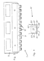
- Figure 1 is a side upper view of a preferred execution of a multi-blades applicator according to the present invention for the taking of a fluid sample to be analyzed according to an electro-phoretic method;
- Figure 2 is an enlarged view of a blade of the applicator of figure 1;
- Figure 3 is a side upper view of a further preferred execution of a multi-blades applicator according to the present invention for the taking of a fluid sample to be analyzed according to an electro-phoretic method;
- Figure 4 is an enlarged view of a blade of the applicator of figure 3;
- Figure 5 is an enlarged view of a third preferred execution of a blade of a multi-blades applicator according to the present invention for the taking of a fluid sample to be analyzed according to an electro-phoretic method; and
- Figure 6 is an enlarged view of a fourth preferred execution of a multi-blades applicator according to the present invention for the taking of a fluid to be analyzed according to an electro-phoretic method.
- A
multi-blades applicator 1 for sampling a fluid to be analyzed in electro-phoretic mode is shown, with reference to figures 1 and 2, comprising a laminarlongitudinal body 3 of theapplicator 1, and aframe 5 for the support of thebody 3 of theapplicator 1 having the thickness of some millimetres and an essentially rectangular shape with longitudinal axis parallel to that of thebody 3 of theapplicator 1. - The
body 3 of the applicator is fixed to theframe 5 by gluing or, as illustrated, by means of a series of buttons 7 of theframe 5 pressure-fitted in the respective holes 9 of thebody 3 of theapplicator 1. - The body of the
applicator 3 is preferably made of stainless steel while theframe 5 can also be made of plastic. - The edge of the part of the
body 3 of theapplicator 1 jutting out from the longitudinal side of thesupport frame 5 is shaped with a series of identical rectangular applyingblades 11 longitudinally aligned. - Each applying
blade 11 comprises in correspondence of a portion of inner blade adrain 13 substantially rectangular longitudinally stretching between the facingside edges blade 11 at a fixed distance from thetip 19 of theblade 11, whichdrain 13 defines a physical barrier for the fluid to be sampled. - Each applying
blade 11 further comprises in a position put between thetip 19 of theblade 11 and thedrain 13 of the blade 11 a longitudinalcalibrated aperture 21 for the retention of a fluid sample. - The
drain 13 of theblade 11 and theaperture 21 of theblade 11 are limited by facingside edges longitudinal edge 27 which separates thedrain 13 of theblade 11 from theaperture 21 of theblade 11 and the width of thelongitudinal edge 29 which separates thetip 19 of theblade 11 from theaperture 21 of theblade 11 are also calibrated. - The size preferred for the applicator is as follows.
- Each
blade 11 has a longitudinal size equal to 4.5 mm and height equal to 4 mm, thedrain 13 of eachblade 11 has height equal to 2 mm, theaperture 21 of each blade has height equal to 0.25 mm and preferably comprised between 0.2 and 0.3 mm, the facingside edges blade 11 have a width equal to 0.375 mm and preferably comprised between 0.35 and 0.4 mm, thelongitudinal edge 27 which separates thedrain 13 of eachblade 11 from theaperture 21 of eachblade 11 has a width equal to 0.1 mm and preferably comprised between 0.05 mm and 0.15 mm, thelongitudinal edge 29 which separates thetip 19 of eachblade 11 from theaperture 21 of eachblade 11 has a width equal to 0.15 mm and preferably comprised between 0.1 mm and 0.2 mm. - A different form of multi-blades applicator for the sampling of a fluid to be analyzed in an electro-phoretic mode is shown, with reference to figures 3 and 4, whose parts equivalent to those of the applicator shown in figures 1 and 2 will be marked with the same numerical reference followed by an apostrophe.
- The applicator 1' comprises a laminar longitudinal body 3' of the applicator 1', and a frame 5' for the support of the body 3' of the applicator 1'.
- The edge of the part of the body 3' of the applicator 1' jutting out from the longitudinal side of the support frame 5' is shaped with a series of identical rectangular applying blades 11' longitudinally aligned.
- Each applying blade 11' comprises in correspondence of a portion of inner blade a drain 13' substantially rectangular longitudinally stretching between the facing side edges 15' and 17' of the blade 11' at a fixed distance from the tip 19' of the blade 11', which drain 13' defines a physical barrier for the fluid to be sampled.
- Each applying blade 11' further comprises in a position put between the tip 19' of the blade 11' and the drain 13' of the blade 11' a series of calibrated apertures 21' longitudinally aligned for the retention of a fluid sample.
- The drain 13' of the blade 11' and the series of apertures 21' of the blade 11' are limited by facing side edges 23' and 25' having calibrated width, so as the width of the longitudinal edge 27' which separates the drain 13' of the blade 11' from the series of apertures 21' of the blade 11' and the width of the longitudinal edge 29' which separates the tip 19' of the blade 11' from the series of apertures 21' of the blade 11' are also calibrated.
- The size preferred for the applicator is as follows.
- Each blade 11' has a longitudinal size equal to 4.5 mm and height equal to 4 mm, the drain 13' of each blade 11' has height equal to 2 mm, the apertures 21' of each blade have height equal to 0.3 mm and preferably comprised between 0.25 and 0.35 mm, width equal to 0.15 mm and preferably comprised between 0.1 mm and 0.2 mm, and distance between centres equal to 0.3 mm and preferably comprised between 0.25 mm and 0.35 mm, the facing side edges 23' and 25' of each blade 11' have a width equal to 0.375 mm and preferably comprised between 0.35 and 0.4 mm, the longitudinal edge 27' which separates the drain 13' of each blade 11' from the apertures 21' of each blade 11' has a width equal to 0.1 mm and preferably comprised between 0.05 mm and 0.15 mm, the longitudinal edge 29' which separates the tip 19' of each blade 11' from the apertures 21' of each blade 11' has a width equal to 0.15 mm and preferably comprised between 0.1 mm and 0.2 mm.
- A third and respectively a fourth form of blade of multi-blades applicator for the sampling of a fluid to be analyzed in an electro-phoretic mode are shown, with reference now to figures 5 and respectively 6, whose parts equivalent to those of the blade shown in figures 2 and respectively 4 will be marked with the same numerical reference followed by two and respectively three apostrophes.
- The applying
blade 11" of figure 5 differs from that of figure 2 only because of the fact that thedrain 13" of theblade 11" now is subdivided into two equal parts separated by a centralcalibrated edge 16 stretching parallely to theside facing edges 15" and 17" of theblade 11" and sized in width like theside facing edges 23" and 25" of theblade 11". - Similarly, the applying
blade 11"' of figure 6 differs from that of figure 4 only because of the fact that thedrain 13"' of theblade 11"' now is subdivided into two equal parts separated by acentral edge 16 stretching parallely to the side facing edges 15''' and 17"' of theblade 11"' and sized in width like theside facing edges 23"' and 25"' of theblade 11"'.
Claims (11)
- Applicator (1) of a fluid sample on a substrate, comprising at least an applying blade (11) substantially of rectangular shape in its turn defining a body of the blade, a tip (19) of the blade and two facing side edges (15,17) of the blade each blade comprising- a drain (13) of the body of the blade stretching between the facing side edges of the blade, said drain defining a physical barrier for the fluid sample; and characterised in said each blade also comprising- at least one calibrated retention aperture (21) of the fluid sample, put between the tip (19) of the blade and the drain (13) of the blade, said at least one aperture (21) being calibrated in order to keep on its inside an exactly defined amount of fluid sample.
- Applicator of a fluid sample on a substrate according to claim 1, characterised in that said drain of the blade has substantially rectangular shape.
- Applicator of a fluid sample on a substrate according to claim 1, characterized in that said drain of the blade is subdivided into two parts separated by a central edge parallel to the side egdes of the blade and having calibrated width.
- Applicator of a fluid sample on a substrate according to claim 1, characterised in that the body of the blade defines two facing edges having calibrated width which laterally limit the drain of the blade.
- Applicator of a fluid sample on a substrate according to claim 1, characterised in that the body of the blade defines an edge having calibrated width which separates the drain of the blade from said at least one aperture of the blade.
- Applicator of a fluid sample on a substrate according to claim 1, characterised in that the body of the blade defines an edge having calibrated width between the tip of the blade and said at least one aperture of the blade.
- Applicator of a fluid sample on a substrate according to claim 1, characterised in that it comprises only one calibrated aperture stretching between the facing side edges of the blade parallelly to the tip of the blade.
- Applicator of a fluid sample on a substrate according to claim 1, characterised in that it comprises a series of calibrated apertures parallelly aligned to the tip of the blade.
- Applicator of a fluid sample on a substrate according to claim 1, characterised in that the body of the applicator is made of stainless steel.
- Applicator of a fluid sample on a substrate according to claim 1, characterised in that it is used for the electro-phoretic analysis of the fluid sample.
- Applicator of a fluid sample on a substrate according to claim 1, characterised in that it comprises a multiplicity of blades aligned along a longitudinal axis of the applicator.
Applications Claiming Priority (2)
| Application Number | Priority Date | Filing Date | Title |
|---|---|---|---|
| ITMI20020367 | 2002-02-25 | ||
| IT2002MI000367A ITMI20020367A1 (en) | 2002-02-25 | 2002-02-25 | APPLICATOR OF A FLUID SAMPLE TO A SUBSTRATE |
Publications (3)
| Publication Number | Publication Date |
|---|---|
| EP1338893A2 EP1338893A2 (en) | 2003-08-27 |
| EP1338893A3 EP1338893A3 (en) | 2004-02-04 |
| EP1338893B1 true EP1338893B1 (en) | 2007-04-04 |
Family
ID=11449362
Family Applications (1)
| Application Number | Title | Priority Date | Filing Date |
|---|---|---|---|
| EP03003117A Expired - Lifetime EP1338893B1 (en) | 2002-02-25 | 2003-02-13 | Applicator of a fluid sample on a substrate |
Country Status (8)
| Country | Link |
|---|---|
| US (1) | US7435388B2 (en) |
| EP (1) | EP1338893B1 (en) |
| JP (1) | JP2003254940A (en) |
| AT (1) | ATE358821T1 (en) |
| DE (1) | DE60312908D1 (en) |
| ES (1) | ES2281574T3 (en) |
| IT (1) | ITMI20020367A1 (en) |
| PT (1) | PT1338893E (en) |
Families Citing this family (5)
| Publication number | Priority date | Publication date | Assignee | Title |
|---|---|---|---|---|
| ITRM20040009A1 (en) * | 2004-01-14 | 2004-04-14 | Interlab S R L | FLUID SAMPLE APPLICATOR ON A MATRIX FOR CHEMICAL ANALYSIS, IN PARTICULAR ELECTROPHORETIC ANALYSIS. |
| JP6099643B2 (en) * | 2012-06-04 | 2017-03-22 | シャープ株式会社 | Electrophoresis cassette and electrophoresis method |
| US9759682B2 (en) * | 2013-08-09 | 2017-09-12 | True Health Ip Llc | Applicator comb for gel electrophoresis |
| HK1226805A1 (en) * | 2013-08-09 | 2017-10-06 | Health Diagnostic Laboratory, Inc. | Applicator comb for gel electrophoresis |
| EP3924729A1 (en) | 2019-02-11 | 2021-12-22 | Agilent Technologies, Inc. | Pre-shaping fluidic sample in a planar way before processing |
Family Cites Families (12)
| Publication number | Priority date | Publication date | Assignee | Title |
|---|---|---|---|---|
| DE1180166B (en) * | 1961-12-06 | 1964-10-22 | Dr Egon Stahl | Broadband pipette, especially for paper and thin layer chromatography as well as for electrophoresis, for applying liquids to sorbent layers |
| US3616387A (en) | 1969-11-13 | 1971-10-26 | Bio Rad Laboratories | Method and apparatus for the transfer of fluid samples |
| US3855846A (en) | 1972-04-07 | 1974-12-24 | Marine Colloids Inc | Sample applicator |
| US4086372A (en) | 1975-10-08 | 1978-04-25 | Helena Laboratories Corporation | Method for applying an organic liquid sample |
| JPS5295491U (en) * | 1976-01-16 | 1977-07-16 | ||
| DE2704096A1 (en) | 1977-02-01 | 1978-08-03 | Bissbort Siegbert Dipl Biologe | Electrophoretic sepn. of protein - with introduction of protein into carrier gel as mixt. with dextran swollen with sucrose soln. |
| JPS5841479Y2 (en) * | 1978-07-20 | 1983-09-19 | オリンパス光学工業株式会社 | Pen tip for serum application |
| JPS5882152A (en) * | 1981-11-10 | 1983-05-17 | Matsushita Electric Ind Co Ltd | electrophoresis device |
| US5217591A (en) | 1990-05-14 | 1993-06-08 | Labintelligence, Inc. | Gel electrophoresis sample applicator/retriever |
| IL112147A (en) | 1994-01-19 | 1999-12-22 | Du Pont | Sample holder and method for automated electrophoresis |
| US5972188A (en) * | 1995-03-03 | 1999-10-26 | Genetic Biosystems, Inc. | Membrane loader for gel electrophoresis |
| EP1007955B1 (en) | 1996-05-06 | 2003-11-26 | Helena Laboratories Corporation | Apparatus for the application of samples on a substrate |
-
2002
- 2002-02-25 IT IT2002MI000367A patent/ITMI20020367A1/en unknown
-
2003
- 2003-02-07 JP JP2003031371A patent/JP2003254940A/en active Pending
- 2003-02-10 US US10/361,213 patent/US7435388B2/en not_active Expired - Fee Related
- 2003-02-13 ES ES03003117T patent/ES2281574T3/en not_active Expired - Lifetime
- 2003-02-13 DE DE60312908T patent/DE60312908D1/en not_active Expired - Lifetime
- 2003-02-13 PT PT03003117T patent/PT1338893E/en unknown
- 2003-02-13 AT AT03003117T patent/ATE358821T1/en not_active IP Right Cessation
- 2003-02-13 EP EP03003117A patent/EP1338893B1/en not_active Expired - Lifetime
Also Published As
| Publication number | Publication date |
|---|---|
| DE60312908D1 (en) | 2007-05-16 |
| ES2281574T3 (en) | 2007-10-01 |
| US20030159934A1 (en) | 2003-08-28 |
| ITMI20020367A1 (en) | 2003-08-25 |
| EP1338893A2 (en) | 2003-08-27 |
| EP1338893A3 (en) | 2004-02-04 |
| ATE358821T1 (en) | 2007-04-15 |
| US7435388B2 (en) | 2008-10-14 |
| PT1338893E (en) | 2007-05-31 |
| ITMI20020367A0 (en) | 2002-02-25 |
| JP2003254940A (en) | 2003-09-10 |
Similar Documents
| Publication | Publication Date | Title |
|---|---|---|
| US8015685B2 (en) | Method for producing a puncturing and measuring device | |
| US7244264B2 (en) | Dual blade lancing test strip | |
| JP5257620B2 (en) | Specimen measuring device protection apparatus and method | |
| CA2267919C (en) | Process for the production of analytical devices | |
| AU742823B2 (en) | Capillary active test element having an intermediate layer situated between the support and the covering | |
| US6098802A (en) | Deep well rack assembly for pipette tips and the like | |
| EP0447888A2 (en) | Device for wiping a reagent strip | |
| EP2363062A1 (en) | Analytical system for detecting an analyte in a body fluid and disposable integrated puncturing and analyzing element | |
| US9279761B1 (en) | Cuvette system | |
| RU2002116402A (en) | Testing device, testing strip, device and method for measuring concentration | |
| CA2629214A1 (en) | Kinked lancet | |
| US7562774B2 (en) | Kit holding adapter | |
| US7435388B2 (en) | Applicator of a fluid sample on a substrate | |
| EP3710164B1 (en) | Sensor cassette | |
| US5569607A (en) | Slide for the microscopic evaluation of liquid specimens | |
| JP7005094B2 (en) | Septum | |
| US8353848B2 (en) | Test device | |
| KR20050072055A (en) | Improved method of lancing skin for the extraction of blood | |
| US10690626B2 (en) | Cassettes for use in automated parallel electrophoretic assays and methods for manufacturing and using same | |
| WO2016127061A1 (en) | Cuvette system | |
| ATE343122T1 (en) | AUTOMATED BIOLOGICAL ANALYSIS DEVICE | |
| KR102028573B1 (en) | Biological sample cutting device | |
| US4870756A (en) | Strip cutter | |
| CN103533890A (en) | Analysis system having a measurement device and a testing element | |
| EP0940181A1 (en) | Pin plate with holder attached to it by clamping or gluing |
Legal Events
| Date | Code | Title | Description |
|---|---|---|---|
| PUAI | Public reference made under article 153(3) epc to a published international application that has entered the european phase |
Free format text: ORIGINAL CODE: 0009012 |
|
| AK | Designated contracting states |
Designated state(s): AT BE BG CH CY CZ DE DK EE ES FI FR GB GR HU IE IT LI LU MC NL PT SE SI SK TR |
|
| AX | Request for extension of the european patent |
Extension state: AL LT LV MK RO |
|
| PUAL | Search report despatched |
Free format text: ORIGINAL CODE: 0009013 |
|
| AK | Designated contracting states |
Kind code of ref document: A3 Designated state(s): AT BE BG CH CY CZ DE DK EE ES FI FR GB GR HU IE IT LI LU MC NL PT SE SI SK TR |
|
| AX | Request for extension of the european patent |
Extension state: AL LT LV MK RO |
|
| 17P | Request for examination filed |
Effective date: 20040304 |
|
| AKX | Designation fees paid |
Designated state(s): AT BE BG CH CY CZ DE DK EE ES FI FR GB GR HU IE IT LI LU MC NL PT SE SI SK TR |
|
| GRAP | Despatch of communication of intention to grant a patent |
Free format text: ORIGINAL CODE: EPIDOSNIGR1 |
|
| GRAS | Grant fee paid |
Free format text: ORIGINAL CODE: EPIDOSNIGR3 |
|
| GRAA | (expected) grant |
Free format text: ORIGINAL CODE: 0009210 |
|
| AK | Designated contracting states |
Kind code of ref document: B1 Designated state(s): AT BE BG CH CY CZ DE DK EE ES FI FR GB GR HU IE IT LI LU MC NL PT SE SI SK TR |
|
| PG25 | Lapsed in a contracting state [announced via postgrant information from national office to epo] |
Ref country code: FI Free format text: LAPSE BECAUSE OF FAILURE TO SUBMIT A TRANSLATION OF THE DESCRIPTION OR TO PAY THE FEE WITHIN THE PRESCRIBED TIME-LIMIT Effective date: 20070404 Ref country code: SI Free format text: LAPSE BECAUSE OF FAILURE TO SUBMIT A TRANSLATION OF THE DESCRIPTION OR TO PAY THE FEE WITHIN THE PRESCRIBED TIME-LIMIT Effective date: 20070404 Ref country code: LI Free format text: LAPSE BECAUSE OF FAILURE TO SUBMIT A TRANSLATION OF THE DESCRIPTION OR TO PAY THE FEE WITHIN THE PRESCRIBED TIME-LIMIT Effective date: 20070404 Ref country code: CH Free format text: LAPSE BECAUSE OF FAILURE TO SUBMIT A TRANSLATION OF THE DESCRIPTION OR TO PAY THE FEE WITHIN THE PRESCRIBED TIME-LIMIT Effective date: 20070404 |
|
| REG | Reference to a national code |
Ref country code: GB Ref legal event code: FG4D |
|
| REG | Reference to a national code |
Ref country code: CH Ref legal event code: EP |
|
| REF | Corresponds to: |
Ref document number: 60312908 Country of ref document: DE Date of ref document: 20070516 Kind code of ref document: P |
|
| REG | Reference to a national code |
Ref country code: IE Ref legal event code: FG4D |
|
| REG | Reference to a national code |
Ref country code: PT Ref legal event code: SC4A Free format text: AVAILABILITY OF NATIONAL TRANSLATION Effective date: 20070517 |
|
| PG25 | Lapsed in a contracting state [announced via postgrant information from national office to epo] |
Ref country code: SE Free format text: LAPSE BECAUSE OF FAILURE TO SUBMIT A TRANSLATION OF THE DESCRIPTION OR TO PAY THE FEE WITHIN THE PRESCRIBED TIME-LIMIT Effective date: 20070704 |
|
| REG | Reference to a national code |
Ref country code: GR Ref legal event code: EP Ref document number: 20070401835 Country of ref document: GR |
|
| ET | Fr: translation filed | ||
| NLV1 | Nl: lapsed or annulled due to failure to fulfill the requirements of art. 29p and 29m of the patents act | ||
| REG | Reference to a national code |
Ref country code: ES Ref legal event code: FG2A Ref document number: 2281574 Country of ref document: ES Kind code of ref document: T3 |
|
| REG | Reference to a national code |
Ref country code: CH Ref legal event code: PL |
|
| PG25 | Lapsed in a contracting state [announced via postgrant information from national office to epo] |
Ref country code: AT Free format text: LAPSE BECAUSE OF FAILURE TO SUBMIT A TRANSLATION OF THE DESCRIPTION OR TO PAY THE FEE WITHIN THE PRESCRIBED TIME-LIMIT Effective date: 20070404 |
|
| PG25 | Lapsed in a contracting state [announced via postgrant information from national office to epo] |
Ref country code: BE Free format text: LAPSE BECAUSE OF FAILURE TO SUBMIT A TRANSLATION OF THE DESCRIPTION OR TO PAY THE FEE WITHIN THE PRESCRIBED TIME-LIMIT Effective date: 20070404 |
|
| PG25 | Lapsed in a contracting state [announced via postgrant information from national office to epo] |
Ref country code: NL Free format text: LAPSE BECAUSE OF FAILURE TO SUBMIT A TRANSLATION OF THE DESCRIPTION OR TO PAY THE FEE WITHIN THE PRESCRIBED TIME-LIMIT Effective date: 20070404 Ref country code: CZ Free format text: LAPSE BECAUSE OF FAILURE TO SUBMIT A TRANSLATION OF THE DESCRIPTION OR TO PAY THE FEE WITHIN THE PRESCRIBED TIME-LIMIT Effective date: 20070404 Ref country code: DK Free format text: LAPSE BECAUSE OF FAILURE TO SUBMIT A TRANSLATION OF THE DESCRIPTION OR TO PAY THE FEE WITHIN THE PRESCRIBED TIME-LIMIT Effective date: 20070404 Ref country code: BG Free format text: LAPSE BECAUSE OF FAILURE TO SUBMIT A TRANSLATION OF THE DESCRIPTION OR TO PAY THE FEE WITHIN THE PRESCRIBED TIME-LIMIT Effective date: 20070704 |
|
| PLBE | No opposition filed within time limit |
Free format text: ORIGINAL CODE: 0009261 |
|
| STAA | Information on the status of an ep patent application or granted ep patent |
Free format text: STATUS: NO OPPOSITION FILED WITHIN TIME LIMIT |
|
| PG25 | Lapsed in a contracting state [announced via postgrant information from national office to epo] |
Ref country code: SK Free format text: LAPSE BECAUSE OF FAILURE TO SUBMIT A TRANSLATION OF THE DESCRIPTION OR TO PAY THE FEE WITHIN THE PRESCRIBED TIME-LIMIT Effective date: 20070404 |
|
| 26N | No opposition filed |
Effective date: 20080107 |
|
| PG25 | Lapsed in a contracting state [announced via postgrant information from national office to epo] |
Ref country code: IT Free format text: LAPSE BECAUSE OF FAILURE TO SUBMIT A TRANSLATION OF THE DESCRIPTION OR TO PAY THE FEE WITHIN THE PRESCRIBED TIME-LIMIT Effective date: 20070404 Ref country code: DE Free format text: LAPSE BECAUSE OF FAILURE TO SUBMIT A TRANSLATION OF THE DESCRIPTION OR TO PAY THE FEE WITHIN THE PRESCRIBED TIME-LIMIT Effective date: 20070705 |
|
| PGFP | Annual fee paid to national office [announced via postgrant information from national office to epo] |
Ref country code: ES Payment date: 20080206 Year of fee payment: 6 |
|
| PGFP | Annual fee paid to national office [announced via postgrant information from national office to epo] |
Ref country code: GB Payment date: 20080129 Year of fee payment: 6 Ref country code: PT Payment date: 20080124 Year of fee payment: 6 |
|
| PGFP | Annual fee paid to national office [announced via postgrant information from national office to epo] |
Ref country code: FR Payment date: 20080228 Year of fee payment: 6 |
|
| PG25 | Lapsed in a contracting state [announced via postgrant information from national office to epo] |
Ref country code: MC Free format text: LAPSE BECAUSE OF NON-PAYMENT OF DUE FEES Effective date: 20080228 |
|
| PG25 | Lapsed in a contracting state [announced via postgrant information from national office to epo] |
Ref country code: EE Free format text: LAPSE BECAUSE OF FAILURE TO SUBMIT A TRANSLATION OF THE DESCRIPTION OR TO PAY THE FEE WITHIN THE PRESCRIBED TIME-LIMIT Effective date: 20070404 Ref country code: IE Free format text: LAPSE BECAUSE OF NON-PAYMENT OF DUE FEES Effective date: 20080213 |
|
| PGFP | Annual fee paid to national office [announced via postgrant information from national office to epo] |
Ref country code: GR Payment date: 20080128 Year of fee payment: 6 |
|
| PG25 | Lapsed in a contracting state [announced via postgrant information from national office to epo] |
Ref country code: CY Free format text: LAPSE BECAUSE OF FAILURE TO SUBMIT A TRANSLATION OF THE DESCRIPTION OR TO PAY THE FEE WITHIN THE PRESCRIBED TIME-LIMIT Effective date: 20070404 |
|
| REG | Reference to a national code |
Ref country code: PT Ref legal event code: MM4A Free format text: LAPSE DUE TO NON-PAYMENT OF FEES Effective date: 20090813 |
|
| GBPC | Gb: european patent ceased through non-payment of renewal fee |
Effective date: 20090213 |
|
| PG25 | Lapsed in a contracting state [announced via postgrant information from national office to epo] |
Ref country code: PT Free format text: LAPSE BECAUSE OF NON-PAYMENT OF DUE FEES Effective date: 20090813 |
|
| REG | Reference to a national code |
Ref country code: FR Ref legal event code: ST Effective date: 20091030 |
|
| PG25 | Lapsed in a contracting state [announced via postgrant information from national office to epo] |
Ref country code: GR Free format text: LAPSE BECAUSE OF NON-PAYMENT OF DUE FEES Effective date: 20090902 |
|
| REG | Reference to a national code |
Ref country code: ES Ref legal event code: FD2A Effective date: 20090214 |
|
| PG25 | Lapsed in a contracting state [announced via postgrant information from national office to epo] |
Ref country code: FR Free format text: LAPSE BECAUSE OF NON-PAYMENT OF DUE FEES Effective date: 20090302 Ref country code: GB Free format text: LAPSE BECAUSE OF NON-PAYMENT OF DUE FEES Effective date: 20090213 |
|
| PG25 | Lapsed in a contracting state [announced via postgrant information from national office to epo] |
Ref country code: ES Free format text: LAPSE BECAUSE OF NON-PAYMENT OF DUE FEES Effective date: 20090214 Ref country code: LU Free format text: LAPSE BECAUSE OF NON-PAYMENT OF DUE FEES Effective date: 20080213 Ref country code: HU Free format text: LAPSE BECAUSE OF FAILURE TO SUBMIT A TRANSLATION OF THE DESCRIPTION OR TO PAY THE FEE WITHIN THE PRESCRIBED TIME-LIMIT Effective date: 20071005 |
|
| PG25 | Lapsed in a contracting state [announced via postgrant information from national office to epo] |
Ref country code: TR Free format text: LAPSE BECAUSE OF FAILURE TO SUBMIT A TRANSLATION OF THE DESCRIPTION OR TO PAY THE FEE WITHIN THE PRESCRIBED TIME-LIMIT Effective date: 20070404 |