EP1338813B1 - Shaft coupling, preferably screw-less steering shaft coupling - Google Patents
Shaft coupling, preferably screw-less steering shaft coupling Download PDFInfo
- Publication number
- EP1338813B1 EP1338813B1 EP02004147A EP02004147A EP1338813B1 EP 1338813 B1 EP1338813 B1 EP 1338813B1 EP 02004147 A EP02004147 A EP 02004147A EP 02004147 A EP02004147 A EP 02004147A EP 1338813 B1 EP1338813 B1 EP 1338813B1
- Authority
- EP
- European Patent Office
- Prior art keywords
- shaft coupling
- shaft
- ring
- splines
- coupling according
- Prior art date
- Legal status (The legal status is an assumption and is not a legal conclusion. Google has not performed a legal analysis and makes no representation as to the accuracy of the status listed.)
- Expired - Lifetime
Links
- 230000008878 coupling Effects 0.000 title claims description 34
- 238000010168 coupling process Methods 0.000 title claims description 34
- 238000005859 coupling reaction Methods 0.000 title claims description 34
- 238000003780 insertion Methods 0.000 claims description 5
- 230000037431 insertion Effects 0.000 claims description 5
- 230000013011 mating Effects 0.000 claims description 3
- 241001272720 Medialuna californiensis Species 0.000 claims 1
- 238000013016 damping Methods 0.000 claims 1
- 230000002093 peripheral effect Effects 0.000 claims 1
- 238000000034 method Methods 0.000 description 3
- 230000000452 restraining effect Effects 0.000 description 3
- 238000010276 construction Methods 0.000 description 2
- 239000000463 material Substances 0.000 description 2
- 238000005192 partition Methods 0.000 description 2
- 230000035515 penetration Effects 0.000 description 2
- 229910000639 Spring steel Inorganic materials 0.000 description 1
- 230000002860 competitive effect Effects 0.000 description 1
- 238000005260 corrosion Methods 0.000 description 1
- 230000007797 corrosion Effects 0.000 description 1
- 230000000694 effects Effects 0.000 description 1
- 230000014759 maintenance of location Effects 0.000 description 1
- 230000000717 retained effect Effects 0.000 description 1
Images



Classifications
-
- B—PERFORMING OPERATIONS; TRANSPORTING
- B62—LAND VEHICLES FOR TRAVELLING OTHERWISE THAN ON RAILS
- B62D—MOTOR VEHICLES; TRAILERS
- B62D1/00—Steering controls, i.e. means for initiating a change of direction of the vehicle
- B62D1/02—Steering controls, i.e. means for initiating a change of direction of the vehicle vehicle-mounted
- B62D1/16—Steering columns
- B62D1/20—Connecting steering column to steering gear
-
- F—MECHANICAL ENGINEERING; LIGHTING; HEATING; WEAPONS; BLASTING
- F16—ENGINEERING ELEMENTS AND UNITS; GENERAL MEASURES FOR PRODUCING AND MAINTAINING EFFECTIVE FUNCTIONING OF MACHINES OR INSTALLATIONS; THERMAL INSULATION IN GENERAL
- F16D—COUPLINGS FOR TRANSMITTING ROTATION; CLUTCHES; BRAKES
- F16D1/00—Couplings for rigidly connecting two coaxial shafts or other movable machine elements
- F16D1/10—Quick-acting couplings in which the parts are connected by simply bringing them together axially
-
- F—MECHANICAL ENGINEERING; LIGHTING; HEATING; WEAPONS; BLASTING
- F16—ENGINEERING ELEMENTS AND UNITS; GENERAL MEASURES FOR PRODUCING AND MAINTAINING EFFECTIVE FUNCTIONING OF MACHINES OR INSTALLATIONS; THERMAL INSULATION IN GENERAL
- F16D—COUPLINGS FOR TRANSMITTING ROTATION; CLUTCHES; BRAKES
- F16D1/00—Couplings for rigidly connecting two coaxial shafts or other movable machine elements
- F16D1/10—Quick-acting couplings in which the parts are connected by simply bringing them together axially
- F16D1/108—Quick-acting couplings in which the parts are connected by simply bringing them together axially having retaining means rotating with the coupling and acting by interengaging parts, i.e. positive coupling
- F16D1/112—Quick-acting couplings in which the parts are connected by simply bringing them together axially having retaining means rotating with the coupling and acting by interengaging parts, i.e. positive coupling the interengaging parts comprising torque-transmitting surfaces, e.g. bayonet joints
-
- Y—GENERAL TAGGING OF NEW TECHNOLOGICAL DEVELOPMENTS; GENERAL TAGGING OF CROSS-SECTIONAL TECHNOLOGIES SPANNING OVER SEVERAL SECTIONS OF THE IPC; TECHNICAL SUBJECTS COVERED BY FORMER USPC CROSS-REFERENCE ART COLLECTIONS [XRACs] AND DIGESTS
- Y10—TECHNICAL SUBJECTS COVERED BY FORMER USPC
- Y10T—TECHNICAL SUBJECTS COVERED BY FORMER US CLASSIFICATION
- Y10T403/00—Joints and connections
- Y10T403/32—Articulated members
- Y10T403/32254—Lockable at fixed position
- Y10T403/32467—Telescoping members
- Y10T403/32475—Telescoping members having detent
- Y10T403/32483—Spring biased
-
- Y—GENERAL TAGGING OF NEW TECHNOLOGICAL DEVELOPMENTS; GENERAL TAGGING OF CROSS-SECTIONAL TECHNOLOGIES SPANNING OVER SEVERAL SECTIONS OF THE IPC; TECHNICAL SUBJECTS COVERED BY FORMER USPC CROSS-REFERENCE ART COLLECTIONS [XRACs] AND DIGESTS
- Y10—TECHNICAL SUBJECTS COVERED BY FORMER USPC
- Y10T—TECHNICAL SUBJECTS COVERED BY FORMER US CLASSIFICATION
- Y10T403/00—Joints and connections
- Y10T403/70—Interfitted members
- Y10T403/7026—Longitudinally splined or fluted rod
- Y10T403/7033—Longitudinally splined or fluted rod including a lock or retainer
Definitions
- the present invention relates to a shaft coupling, preferably a steering shaft coupling. More in detail the invention relates to an improved coupling between a first shaft section and a second shaft section, as stated in the preamble of claim 1.
- a prior art construction shows a connector (12) adapted to connect a steering column (10) to a steering gear.
- This connector (12) comprises a first yoke (20), secured to a steering column (10) and a second yoke (22), connected to a shaft (14) of a control valve (16) related to a steering mechanism.
- Connecting means (28, 30, 32, 34, 46) are provided for a snap-fit of the second yoke (22) onto the shaft (14) of the control valve (16) and restraining means, as splines (48), are provided for restraining the second yoke (22) from rotating relative to the shaft (14).
- This restraining means is including a lash adjuster (34), coupled to the shaft (14), and cooperable with the second yoke (22) for substantially eliminating lash in the connector (12).
- a clip (36), a retaining ring (28), a delashing element (34) and a further clip (42) are assembled onto the shaft (14) before the control valve (16) is fitted to the vehicle.
- the yoke (20), via a universal joint (18), is fixed to the steering column.
- the steering column (10) is then fitted to the vehicle, in the process of which the body portion (32) is aligned with the delashing element (34) so that their respective splines mates.
- the body portion (32) is then urged over the ring (28), at which time the bevelled edge begins to compress the ring (28).
- the body portion As the body portion reaches the top of the shaft (14) it is aligned with the splines of the shaft (14) and, on application of a further force, is compressed fully to fit within the body portion (32). During this time the coil spring arrangement (36) begins to be compressed.
- GB-A-2 270 054 discloses further a snap fit steering column connection, having an external spring for axially biasing the joint.
- the device of this patent will require an additional retention ring and spring, both of which are subject to corrosion and loss of structure integrity because of their exterior mounting and both of which present cost over and above that required by the present inventive coupling.
- the section (3') and the ring arrangement (22) are adapted to be pressed through splines in a hole (20) of a yoke (8).
- EP-A1-0 300 854 discloses an axially engageable steering coupling having a snap ring retainer but no axially biasing structure.
- Another object with the present invention is to present a safe, easy to assemble and disassemble arrangement, which also is suitable for an automated assembly process.
- Yet another object with the invention is to eliminate or dampen such play and thus unwanted noise that always will occur in an assembly made by splines, which is manufactured to industrial standards.
- one of either the first or the second shaft i.e. the one having an outer serration (male portion), in a portion thereof to be inserted in the mating inner serration (female portion) is provided with a groove for the fitting of a radially elastical locking arrangement for upon insertion of said male portion into the female portion, co-operation with a corresponding circumferentially extending groove or shoulder arranged in the latter. Due to the small number of parts comprised in the coupling quick and easy assembly is achieved, which also makes it suitable and easy to implement in an automated assembly station.
- said groove for a locking ring is located in a diameter reduced foremost end of said male portion. Due to the fact that thereby no torque is transferred through the part of the shaft where the shafts are kept together, the thickness of material of said foremost end may be of a smaller dimension, which except for saving weight also makes assembly easier.
- Fig 1 shows a complete coupling unit A of one embodiment of the invention as an exploded view.
- a leftmost portion constitutes a male portion 1 (shaft) of the coupling.
- the male portion is here an end portion of a steering column of a car. Said male portion 1 will be further described below.
- two further portions namely an elastic and/or flexible ring 3 and a locking ring 4 are located. The assembly, location as well as the function of the parts or portions is described below.
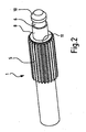
- Fig 2 which is a perspective view of the male portion 1 and which more clearly shows the same as being an end part of a shaft emanating from for instance a steering column of a car.
- the male portion 1 comprise an outer splines section 5, while it, as shown from fig 2, the foremost right end, after said splines section 5, in a consecutive fashion comprise from left to right an outside cylindrical shoulder 8, a groove 6 and a chamfered tip 10.
- each outer tip 11 (rightmost in Fig 2) of the elements in the splines 5 is pointed.
- the female portion 2 is shown as a cut perspective view in Fig 3. As oriented therein its leftmost end is its penetration end 9, i.e. where the male portion 1 is to penetrate the same. Said end 9 comprise a conically shaped entry 12 in which the initial portion of inner splines 13, following thereafter, has a more or less conform shape to the pointed shape of the outer splines tips 11 of the male portion 1 counterpart, i.e. each outer tip 25 of the inner splines 13 is pointed.
- the female portion transforms into a chamfered or frusto conical throat section 14 ending with a neck 15, which in turn leads to a shoulder 16.
- the portion 2 being a hollow shaft, is in radial direction to said axis penetrated threefold by holes H with a partition of 120°.
- the flexible or elastic ring 3 is in Fig 4 depicted in an enlarged perspective view.
- said ring 3 is to be sandwiched between the male and female portions 1 and 2, respectively, supported on the one hand by the shoulder 8 of the male portion 1 and on the other by the throat section 14 of the female portion 2.
- the ring 3 partly has a hollow cylindrical form, (in leftmost portion of Fig 4) at 17, and partly a hollow frusto conical or chamfered form, (in rightmost portion of Fig 4) at 18, which shape not fully corresponds to the space between the abovementioned male and female portions 1 and 2 respectively, in their assembled form, since the ring 3 requires some extra space for its deformation during forced or positive assembly of the coupling.
- the inner shape of the ring 3 has a suitable tolerance close to forced fit set in relation to its shaft.
- Fig 5 locking means in the form of a ring 4 for positively keeping an assembled coupling together, is shown.
- Said ring 4 is preferably made from spring steel, however, other materials such as a plastic possessing adequate properties may also be used.
- the outside of the locking ring 4 in part has a hollow cylindrical form, (in leftmost portion of Fig 5) at 20 where also its locking edge 19 is situated, and in part a hollow frusto conical form, (in rightmost portion of Fig 5) at 21.
- the inside of the ring 4 is in its relaxed state cylindrical with a specific loose fit dimension (see below) in relation to that of the male portion 1 groove 6.
- the overall diametrical dimensions of the ring 4, inside as well as outside are such that due to the fact that the ring 4 is provided with a notch 22, extending obliquely or spiral wise relative to the main axis thereof, said ring 4 may be positively diametrically urged to a smaller dimension during fitting as well as in a ready state, during which conditions said ring 4 at its extreme almost fully enclose the groove 6.
- Fig 6 shows an alternative embodiment of a locking means for the same purpose as that of the ring 4 according to Fig 5.
- the locking means according to Fig 6 comprise two identical semi-cylindrical pieces 23, adapted to fit the groove 6 of the male portion 1 and engage the same with locking edges 19.
- the pieces 23 are positively urged towards a relaxed position by a spring 24, diametrically arranged between said pieces 23.
- the spring 24 must for obvious reasons be arranged in a through hole (not shown) of the male portion 1.
- the different parts of the steering shaft coupling according to the embodiment shown is supposed to interact as follows.
- the elastic ring 3 Before fitting the male portion1 in its counterpart, the elastic ring 3 is fitted to rest against the shoulder 8 of the male portion 1.
- the ring 3 may be forced into its position on the shaft end by making use of diametrical elasticity in the ring 3.
- the locking ring 4 as depicted in Fig 5 or possibly an arrangement of semi cylindrical pieces 23 and a spring 24 as depicted in Fig 6, is positively fitted to the end of the male portion 1, more precisely to the groove 6.
- the female portion 2 is penetrated by the male portion 1 under a slight axial pressure, whereupon the locking ring 4 or the cylindrical pieces 23 with its respective locking edges 19 are supposed to attain a locked position in cooperation with the shoulder 16 of the female portion.
- the applied axial pressure has to be large enough to elastically deform the elastic or flexible ring 3 to such an extent that the locking ring 4 or the semi-cylindrical pieces 23 may pass the throat section 14 as well as the neck 15 of the female portion 2, whereby the element/-s in question with its locking edges 19 enters into a locking engagement with the shoulder 16 of the female portion 2.
- the male portion 1 as well as the female portion 2 and the elastic or flexible ring 3, it is mentioned that these parts each comprise at least one conical, frusto conical and/or chamfered surface or portion.
- the chamfered tip portion 10 at the very end thereof (the rightmost end according to Fig 2) is supposed to aid the initial insertion of the male portion 1 into the corresponding female portion 2.
- each tip 11 of the elements of the splines 5 to be further inserted are as mentioned above pointed. This feature aids the further insertion by eliminating the risk that the end of the splines 5 climbs on the ends of its counterpart (a position top-on-top), the inner splines 13.
- the female portion 2 its chamfered portion 14 is supposed to establish a support surface for taking up axial as well as radial forces due to play between the splines elements of the male and female portions to thereby minimize the risk of generating unnecessary noise which could impede the quality feeling of the product as a whole.
- the chamfered part 14 of the female portion 2 counteracts with the chamfered portion at 18 of the elastic or flexible ring 3 to, when this ring deforms uniformly, elastically bias the coupling, whereby no noise even due to surrounding vibrations is escalated.
- the locking ring 4 according to Fig 5, which also comprise a frusto conical or chamfered portion at 21.
- the female portion 2 comprises the above-mentioned holes H.
- a specially designed tool (not shown) is used for this purpose, which tool employs three movable fingers to be inserted through said holes for uniformly deforming the locking ring to such an extent that it becomes possible to withdraw the male portion from its mating female counterpart, to thereby detach the coupling unit A.
- the invention shall not be delimited by the description given above, it is instead to be understood that the invention should cover all subject matter defined by the enclosed claims.
Landscapes
- Engineering & Computer Science (AREA)
- General Engineering & Computer Science (AREA)
- Mechanical Engineering (AREA)
- Chemical & Material Sciences (AREA)
- Combustion & Propulsion (AREA)
- Transportation (AREA)
- Steering Controls (AREA)
- Snaps, Bayonet Connections, Set Pins, And Snap Rings (AREA)
Description
- The present invention relates to a shaft coupling, preferably a steering shaft coupling. More in detail the invention relates to an improved coupling between a first shaft section and a second shaft section, as stated in the preamble of claim 1.
- When nowadays assembling vehicles like a car it is for competitive reasons more critical than ever to be able to do so within a minimum amount of hours.
Simultaneously the building density of cars has during the last ten or so years been driven to its outer limits for reasons of capability of carrying a vast amount of features in spite of a more and more limited outer format.
Thus some assembling operations become difficult and time consuming to perform in such limited time whilst all previous requirements concerning quality, function, performance and of course safety are features that are musts to be upheld.
Under these circumstances the use of conventional fastening means such as screws or nuts, as is the case, is complicated and time consuming, while such use also require at least one time consuming and of course thereby costly control station in the assembly process to really check that nothing has been overlooked in previous asse bly stages. - A prior art construction, as disclosed in patent publication GB-A-2 270 054, shows a connector (12) adapted to connect a steering column (10) to a steering gear.
- This connector (12) comprises a first yoke (20), secured to a steering column (10) and a second yoke (22), connected to a shaft (14) of a control valve (16) related to a steering mechanism.
- Connecting means (28, 30, 32, 34, 46) are provided for a snap-fit of the second yoke (22) onto the shaft (14) of the control valve (16) and restraining means, as splines (48), are provided for restraining the second yoke (22) from rotating relative to the shaft (14).
- This restraining means is including a lash adjuster (34), coupled to the shaft (14), and cooperable with the second yoke (22) for substantially eliminating lash in the connector (12).
- In Figure 2 it is clearly shown that the splines, related to the shaft (14), are divided into two sections, one longer section, surrounded by a coil spring arrangement (36), and a shorter section (50).
- A clip (36), a retaining ring (28), a delashing element (34) and a further clip (42) are assembled onto the shaft (14) before the control valve (16) is fitted to the vehicle.
- More precisely it is here suggested that, before fitting the steering column to the vehicle, the yoke (20), via a universal joint (18), is fixed to the steering column.
- Once this is done the steering column (10) is then fitted to the vehicle, in the process of which the body portion (32) is aligned with the delashing element (34) so that their respective splines mates.
- The body portion (32) is then urged over the ring (28), at which time the bevelled edge begins to compress the ring (28).
- As the body portion reaches the top of the shaft (14) it is aligned with the splines of the shaft (14) and, on application of a further force, is compressed fully to fit within the body portion (32). During this time the coil spring arrangement (36) begins to be compressed.
- As soon as the ring (28) becomes aligned with a channel (30) it expands to its normal diameter so as to lie partly in a first channel (30) and partly in a second channel, the latter formed on the shaft (14). This causes the ring (28) to lock the yoke (22) to the shaft (14).
- GB-A-2 270 054 discloses further a snap fit steering column connection, having an external spring for axially biasing the joint.
- Because the biasing spring is mounted externally of the joint, the device of this patent will require an additional retention ring and spring, both of which are subject to corrosion and loss of structure integrity because of their exterior mounting and both of which present cost over and above that required by the present inventive coupling.
- The construction, shown and described in the patent publication EP-A1-0 300 854, also gives advise of a shaft (3) having splines (20) divided into two sections (an upper section 3') and where these sections are interrelated by an elastic ring arrangement (22).
- The section (3') and the ring arrangement (22) are adapted to be pressed through splines in a hole (20) of a yoke (8).
- EP-A1-0 300 854 discloses an axially engageable steering coupling having a snap ring retainer but no axially biasing structure.
- The coupling of this patent will thus be prone to unwanted vibration caused by unwanted axial movement.
- Therefore it is an object with the present invention to achieve a solution that makes it easier and quicker to assemble a steering shaft to a steering gear while necessary aspects relating to quality, function, performance and safety, well conserved in previous solutions, are retained.
- Another object with the present invention is to present a safe, easy to assemble and disassemble arrangement, which also is suitable for an automated assembly process.
- Yet another object with the invention is to eliminate or dampen such play and thus unwanted noise that always will occur in an assembly made by splines, which is manufactured to industrial standards.
- According to the present invention one of either the first or the second shaft, i.e. the one having an outer serration (male portion), in a portion thereof to be inserted in the mating inner serration (female portion) is provided with a groove for the fitting of a radially elastical locking arrangement for upon insertion of said male portion into the female portion, co-operation with a corresponding circumferentially extending groove or shoulder arranged in the latter.
Due to the small number of parts comprised in the coupling quick and easy assembly is achieved, which also makes it suitable and easy to implement in an automated assembly station. - In a further developed embodiment of the invention said groove for a locking ring is located in a diameter reduced foremost end of said male portion. Due to the fact that thereby no torque is transferred through the part of the shaft where the shafts are kept together, the thickness of material of said foremost end may be of a smaller dimension, which except for saving weight also makes assembly easier.
- By also providing the very foremost end of the male portion with a chamfered top, assembly is to an even greater extent made easier in that the initial insertion of the male portion may be made with less exactness.
- Due to the location of a dampening rubber ring between an axial fixation of the joint and the splines or serration of its torque transmitting coupling, the elements of the coupling to a large extent becomes isolated from vibrations carried over from other components of its implement, for instance a car.
Further objects of the invention are various from the claims. - Below the invention is described more in detail with reference to accompanying drawings illustrating a preferred embodiment of the invention, and in which,
- Fig 1 shows as an exploded in part cut view in consecutive order all parts constituting a steering shaft coupling according to the invention,
- Fig 2 shows in a perspective view and as a separate element a male portion of said coupling,
- Fig 3, again as a separate element in a cut slight perspective view shows a corresponding female portion of said coupling,
- Fig 4 shows a perspective view of an elastic element being used as a biasing means between the male and female portion respectively,
- Fig 5 shows a perspective view of a diametrically compressible locking ring for positively keeping the coupling as a whole in its assembled state, to be situated in the vicinity of the foremost end of the male coupling portion, and
- Fig 6 shows a perspective view of an alternative embodiment of a locking arrangement.
- Referring now to the accompanying drawings, Fig 1 shows a complete coupling unit A of one embodiment of the invention as an exploded view. As viewed on the drawing a leftmost portion constitutes a male portion 1 (shaft) of the coupling. The male portion is here an end portion of a steering column of a car. Said male portion 1 will be further described below. Between the male portion 1 and its corresponding female portion 2 (socket), two further portions, namely an elastic and/or
flexible ring 3 and alocking ring 4 are located. The assembly, location as well as the function of the parts or portions is described below. - Fig 2, which is a perspective view of the male portion 1 and which more clearly shows the same as being an end part of a shaft emanating from for instance a steering column of a car. The male portion 1 comprise an
outer splines section 5, while it, as shown from fig 2, the foremost right end, after saidsplines section 5, in a consecutive fashion comprise from left to right an outsidecylindrical shoulder 8, agroove 6 and achamfered tip 10. It should also be noted that each outer tip 11 (rightmost in Fig 2) of the elements in thesplines 5 is pointed. By the location of thegroove 6 and thereby the joint between the shaft portions close to the end of the male portion, as discussed above, no rotative torque will ever be transmitted through said joint. This is due to that all the torque is transmitted via the splines of the shaft portions. Said torque will thereby have no dimensioning effect on the joint, whereby its dimensions may be kept smaller, which inevitably will make assembly easier and also will save weight. - The
female portion 2 is shown as a cut perspective view in Fig 3. As oriented therein its leftmost end is its penetration end 9, i.e. where the male portion 1 is to penetrate the same. Said end 9 comprise a conically shaped entry 12 in which the initial portion ofinner splines 13, following thereafter, has a more or less conform shape to the pointed shape of theouter splines tips 11 of the male portion 1 counterpart, i.e. eachouter tip 25 of theinner splines 13 is pointed. At the rightmost end of thesplines 13, the female portion transforms into a chamfered or frustoconical throat section 14 ending with aneck 15, which in turn leads to ashoulder 16. As seen along the axis of thefemale portion 2, close to theshoulder 16, theportion 2, being a hollow shaft, is in radial direction to said axis penetrated threefold by holes H with a partition of 120°. - The flexible or
elastic ring 3 is in Fig 4 depicted in an enlarged perspective view. In the assembled form of the coupling, saidring 3 is to be sandwiched between the male andfemale portions 1 and 2, respectively, supported on the one hand by theshoulder 8 of the male portion 1 and on the other by thethroat section 14 of thefemale portion 2. Thering 3 partly has a hollow cylindrical form, (in leftmost portion of Fig 4) at 17, and partly a hollow frusto conical or chamfered form, (in rightmost portion of Fig 4) at 18, which shape not fully corresponds to the space between the abovementioned male andfemale portions 1 and 2 respectively, in their assembled form, since thering 3 requires some extra space for its deformation during forced or positive assembly of the coupling. The inner shape of thering 3 has a suitable tolerance close to forced fit set in relation to its shaft. - In Fig 5 locking means in the form of a
ring 4 for positively keeping an assembled coupling together, is shown. Saidring 4 is preferably made from spring steel, however, other materials such as a plastic possessing adequate properties may also be used. Like theflexible ring 3, shown in Fig 4, the outside of thelocking ring 4 in part has a hollow cylindrical form, (in leftmost portion of Fig 5) at 20 where also itslocking edge 19 is situated, and in part a hollow frusto conical form, (in rightmost portion of Fig 5) at 21. The inside of thering 4 is in its relaxed state cylindrical with a specific loose fit dimension (see below) in relation to that of the male portion 1groove 6. Further the overall diametrical dimensions of thering 4, inside as well as outside are such that due to the fact that thering 4 is provided with anotch 22, extending obliquely or spiral wise relative to the main axis thereof, saidring 4 may be positively diametrically urged to a smaller dimension during fitting as well as in a ready state, during which conditions saidring 4 at its extreme almost fully enclose thegroove 6. - Fig 6 shows an alternative embodiment of a locking means for the same purpose as that of the
ring 4 according to Fig 5. The locking means according to Fig 6 comprise two identicalsemi-cylindrical pieces 23, adapted to fit thegroove 6 of the male portion 1 and engage the same with locking edges 19. Thepieces 23 are positively urged towards a relaxed position by aspring 24, diametrically arranged between saidpieces 23. Thespring 24 must for obvious reasons be arranged in a through hole (not shown) of the male portion 1. - As is best seen in Fig 1 the different parts of the steering shaft coupling according to the embodiment shown is supposed to interact as follows. Before fitting the male portion1 in its counterpart, the
elastic ring 3 is fitted to rest against theshoulder 8 of the male portion 1. Thering 3 may be forced into its position on the shaft end by making use of diametrical elasticity in thering 3. Thereafter thelocking ring 4 as depicted in Fig 5 or possibly an arrangement of semicylindrical pieces 23 and aspring 24 as depicted in Fig 6, is positively fitted to the end of the male portion 1, more precisely to thegroove 6.
Thereafter thefemale portion 2 is penetrated by the male portion 1 under a slight axial pressure, whereupon thelocking ring 4 or thecylindrical pieces 23 with its respective locking edges 19 are supposed to attain a locked position in cooperation with theshoulder 16 of the female portion. The applied axial pressure has to be large enough to elastically deform the elastic orflexible ring 3 to such an extent that thelocking ring 4 or thesemi-cylindrical pieces 23 may pass thethroat section 14 as well as theneck 15 of thefemale portion 2, whereby the element/-s in question with its locking edges 19 enters into a locking engagement with theshoulder 16 of thefemale portion 2.
In connection with the above description of the male portion 1 as well as thefemale portion 2 and the elastic orflexible ring 3, it is mentioned that these parts each comprise at least one conical, frusto conical and/or chamfered surface or portion. Regarding the male portion 1, the chamferedtip portion 10 at the very end thereof (the rightmost end according to Fig 2) is supposed to aid the initial insertion of the male portion 1 into the correspondingfemale portion 2. Having been aided by saidchamfer 10, eachtip 11 of the elements of thesplines 5 to be further inserted are as mentioned above pointed. This feature aids the further insertion by eliminating the risk that the end of thesplines 5 climbs on the ends of its counterpart (a position top-on-top), theinner splines 13.
Regarding thefemale portion 2, its chamferedportion 14 is supposed to establish a support surface for taking up axial as well as radial forces due to play between the splines elements of the male and female portions to thereby minimize the risk of generating unnecessary noise which could impede the quality feeling of the product as a whole. Thechamfered part 14 of thefemale portion 2 counteracts with the chamfered portion at 18 of the elastic orflexible ring 3 to, when this ring deforms uniformly, elastically bias the coupling, whereby no noise even due to surrounding vibrations is escalated.
Regarding thelocking ring 4 according to Fig 5, which also comprise a frusto conical or chamfered portion at 21. This chamfer is used to facilitate the deformation of thering 4 while it passes the throat andneck portions female portion 2.
Regarding a future possible disassembly of the coupling A, thefemale portion 2 comprises the above-mentioned holes H. A specially designed tool (not shown) is used for this purpose, which tool employs three movable fingers to be inserted through said holes for uniformly deforming the locking ring to such an extent that it becomes possible to withdraw the male portion from its mating female counterpart, to thereby detach the coupling unit A.
The invention shall not be delimited by the description given above, it is instead to be understood that the invention should cover all subject matter defined by the enclosed claims. -
- 1.
- male portion
- 2
- female portion
- 3.
- elastic or flexible ring
- 4.
- locking ring
- 5.
- splines portion of male port.
- 6.
- groove
- 7.
- foremost end of male portion
- 8.
- shoulder
- 9.
- penetration end of female portion
- 10
- chamfered tip
- 11
- tips of splines
- 12.
- conically shaped entry
- 13.
- inner splines
- 14.
- chamfered or frusto conical throat section
- 15.
- neck
- 16
- shoulder
- 17.
- hollow cylindrical portion of ring
- 18
- frusto conical portion of
flexible ring 3 - 19
- locking edge of
ring 4 - 20
- leftmost portion of locking ring, in Fig 5
- 21
- rightmost portion of locking ring in Fig 5
- 22.
- notch
- 23
- semi-cylindrical pieces
- 24.
- spring
- "A". coupling unit
- "H." holes at 120° partition
Claims (8)
- A shaft coupling (A) between a first shaft section (1) and a second shaft section (2), which when in an operative position, are oriented along a common longitudinal axis, and wherein said first and second shaft sections (1, 2) comprise inner and/or outer splines or other serration (5, 13) respectively for the interconnection of said first and second shafts sections (1, 2) respectively, whereby one of said, either the first or the second, shaft sections (1, 2) having an outer splines or serration (male portion) in a portion thereof to be inserted into a mating inner splines or serration (female portion) of the other shaft section is provided with a groove (6) for the fitting of a radially elastically deformable locking arrangement (4; 23, 24) for, upon insertion thereof into the female portion, co-operating with a corresponding radially extending groove or shoulder (16) arranged in the latter, characterized in that a vibration damping elastic or flexible ring (3) is applied to a rearmost end of a diameter reducing foremost end (7) of said male portion (1), that said ring (3) is oriented or sandwiched between a shoulder (8), arranged on the male portion (1), and a throat section (14) of the female portion (2) in order to, in respect of vibrations, isolate said two shaft sections from each other and in that said flexible ring is conically shaped at its foremost peripheral surface in order to, under bias, be able to carry both radial and axial loads from a corresponding throat section (14) surface in the female portion.
- Shaft coupling according to claim 1, characterized by said locking arrangement having a form of an elastically deformable locking ring (4), formed in one single piece.
- Shaft coupling according to claim 1 or 2, characterized by said locking arrangement having a form of two half-moon shaped or partially circular rings (23), being biased by a spring means (24) therebetween, arranged in a diameter through a hole (H) at a bottom of a female portion groove (16).
- Shaft coupling according to anyone of the preceding claims 1 to 3, characterized in that said groove is circular (6) and is arranged within said diameter reducing foremost end section (7) of said male portion (1).
- Shaft coupling according to claim 4, characterized in that the end of said foremost end section (7) of said male portion (1) is formed as a chamfered top (10).
- Shaft coupling according to anyone of the preceding claims, characterized in that each outer tip (11) of the splines or serrations (5) on the male portion (1) is pointed.
- Shaft coupling according to anyone of the preceding claims, characterized in that an entry region (9) of said female portion (2) is slightly chamfered (12), and that each outer tip (25) of the splines or serrations (13) of the female portion (2) is pointed.
- Shaft coupling according to claim 5, characterized in that the locking ring is conically shaped.
Priority Applications (3)
| Application Number | Priority Date | Filing Date | Title |
|---|---|---|---|
| EP02004147A EP1338813B1 (en) | 2002-02-25 | 2002-02-25 | Shaft coupling, preferably screw-less steering shaft coupling |
| DE60215911T DE60215911T2 (en) | 2002-02-25 | 2002-02-25 | Clutch, preferably clutch of a motor vehicle steering column shaft without screws |
| US10/248,844 US7198425B2 (en) | 2002-02-25 | 2003-02-24 | Steering shaft coupling for automotive vehicle |
Applications Claiming Priority (1)
| Application Number | Priority Date | Filing Date | Title |
|---|---|---|---|
| EP02004147A EP1338813B1 (en) | 2002-02-25 | 2002-02-25 | Shaft coupling, preferably screw-less steering shaft coupling |
Publications (2)
| Publication Number | Publication Date |
|---|---|
| EP1338813A1 EP1338813A1 (en) | 2003-08-27 |
| EP1338813B1 true EP1338813B1 (en) | 2006-11-08 |
Family
ID=27635832
Family Applications (1)
| Application Number | Title | Priority Date | Filing Date |
|---|---|---|---|
| EP02004147A Expired - Lifetime EP1338813B1 (en) | 2002-02-25 | 2002-02-25 | Shaft coupling, preferably screw-less steering shaft coupling |
Country Status (3)
| Country | Link |
|---|---|
| US (1) | US7198425B2 (en) |
| EP (1) | EP1338813B1 (en) |
| DE (1) | DE60215911T2 (en) |
Families Citing this family (31)
| Publication number | Priority date | Publication date | Assignee | Title |
|---|---|---|---|---|
| US7354216B2 (en) * | 2005-04-12 | 2008-04-08 | Honeywell International, Inc. | Grease seal cup to retain lubrication for life extension in existing splined joint |
| US7574940B2 (en) * | 2005-11-23 | 2009-08-18 | Delphi Technologies, Inc. | Steering column assembly including anti-rotation device |
| US20090199375A1 (en) * | 2006-01-20 | 2009-08-13 | Fred Koelling | Latching system |
| US7717463B2 (en) * | 2007-04-14 | 2010-05-18 | Fong Jian-Jhong | Steering column set with changeable angle and length |
| US8133142B2 (en) * | 2007-05-08 | 2012-03-13 | Dunkermotoren Gmbh | Belt pulley for the output shaft of a gear, gear, electric motor, and output shaft |
| US7681349B2 (en) * | 2007-09-20 | 2010-03-23 | Dicke Tool Company | Hand operated traffic signal device |
| US20090077848A1 (en) * | 2007-09-20 | 2009-03-26 | Dicke Grant D | Hand operated traffic signal device |
| US20090217493A1 (en) * | 2008-02-26 | 2009-09-03 | Michael Greenhill | Hoop retaining ring |
| USD644905S1 (en) * | 2009-06-30 | 2011-09-13 | A. Richard Tools Co./Outils A. Richard Co. | Flexible pole extension |
| US8491408B2 (en) * | 2009-10-07 | 2013-07-23 | Taylor Made Golf Company, Inc. | Golf club shaft |
| DE102010005830A1 (en) * | 2010-01-27 | 2011-07-28 | GM Global Technology Operations LLC, ( n. d. Ges. d. Staates Delaware ), Mich. | Gear arrangement for a motor vehicle |
| JP5293641B2 (en) * | 2010-03-01 | 2013-09-18 | 日本精工株式会社 | Steering device |
| DE102011109691A1 (en) * | 2011-08-06 | 2013-02-07 | Daimler Ag | The steering spindle arrangement |
| KR101405591B1 (en) * | 2011-10-24 | 2014-06-10 | 주식회사 만도 | Steering shaft with miss-assembly prevention structure |
| US20140116184A1 (en) * | 2012-10-31 | 2014-05-01 | Michael W. Clark | Steering wheel retention assembly |
| US9919279B2 (en) * | 2012-12-17 | 2018-03-20 | B&P Littleford Llc | Shaft spacing flange for a kneading machine |
| US9157482B2 (en) | 2013-10-11 | 2015-10-13 | Steering Solutions Ip Holding Corporation | Shaft assembly with anti-pull apart stake |
| JP5745604B2 (en) * | 2013-12-17 | 2015-07-08 | 株式会社山田製作所 | Steering device |
| JP6372455B2 (en) * | 2015-09-07 | 2018-08-15 | トヨタ自動車株式会社 | Power transmission device for vehicle |
| DE102015219644A1 (en) * | 2015-10-09 | 2017-04-13 | Ford Global Technologies, Llc | Plug connection between a steering wheel and a handlebar and steering wheel and handlebar to form a connector |
| DE102016215023B4 (en) * | 2016-08-11 | 2023-02-02 | Thyssenkrupp Ag | Method for manufacturing a length-adjustable steering shaft and length-adjustable steering shaft |
| US10641315B2 (en) * | 2017-04-04 | 2020-05-05 | Steering Solutions Ip Holding Corporation | Steering shaft assembly having anti-pull apart feature |
| DE102017221075B4 (en) * | 2017-11-24 | 2019-06-27 | Thyssenkrupp Ag | Steering shaft for a motor vehicle |
| US12460666B2 (en) * | 2018-11-16 | 2025-11-04 | Jameson, Llc | Ferrules for pole and tool extension |
| JP7079756B2 (en) * | 2019-09-05 | 2022-06-02 | 川崎車両株式会社 | handrail |
| US11384827B2 (en) | 2019-11-25 | 2022-07-12 | Steering Solutions Ip Holding Corporation | Electric power steering polymer drive pulley |
| EP3913248B1 (en) | 2020-05-20 | 2023-07-05 | Hitachi Energy Switzerland AG | A shaft system |
| DE102021115898B4 (en) | 2021-06-18 | 2023-04-20 | Alexandra Kuhnle | shaft-hub connection |
| DE102022201802A1 (en) | 2022-02-22 | 2023-08-24 | Zf Friedrichshafen Ag | Bearing arrangement of two shafts |
| DE102022116887A1 (en) * | 2022-07-06 | 2024-01-11 | Stabilus Gmbh | Shaft-hub assembly |
| DE102024201712A1 (en) * | 2024-02-23 | 2025-08-28 | Zf Friedrichshafen Ag | Arrangement with a first component and a second component |
Citations (1)
| Publication number | Priority date | Publication date | Assignee | Title |
|---|---|---|---|---|
| US4124318A (en) * | 1978-03-23 | 1978-11-07 | General Motors Corporation | Splined assembly with retaining rings |
Family Cites Families (21)
| Publication number | Priority date | Publication date | Assignee | Title |
|---|---|---|---|---|
| US3279835A (en) * | 1964-02-12 | 1966-10-18 | Anderson Co | Adapter |
| US3588154A (en) * | 1968-10-29 | 1971-06-28 | Bendix Corp | Torque coupling device |
| US3531144A (en) * | 1969-02-27 | 1970-09-29 | Ingersoll Rand Co | Retainer ring |
| US3832076A (en) * | 1972-09-25 | 1974-08-27 | Gen Motors Corp | Splined assembly with retaining rings |
| US3962931A (en) * | 1975-03-21 | 1976-06-15 | International Harvester Company | Telescopic steering column |
| FR2427506A1 (en) * | 1978-06-02 | 1979-12-28 | Citroen Sa | ELASTIC RING FOR IMMOBILIZATION OF RIBBED OR TOOTHED PARTS |
| JPS6034048U (en) * | 1983-08-17 | 1985-03-08 | 日産自動車株式会社 | steering device |
| FR2618502B1 (en) * | 1987-07-24 | 1989-10-27 | Renault | DEVICE FOR COUPLING A MECHANISM WITH A STEERING SHAFT |
| FR2616399B1 (en) * | 1987-12-09 | 1989-10-20 | Ecia Equip Composants Ind Auto | DEVICE FOR PROVIDING THE FINE ADJUSTMENT OF THE SETTING OF THE ANGULAR ORIENTATION OF A STEERING WHEEL ON AN AUTOMOTIVE STEERING SHAFT |
| GB2256027A (en) | 1991-05-24 | 1992-11-25 | Torrington Co | Adjustable length vehicle steering column |
| DE4207839C2 (en) * | 1992-03-12 | 1993-12-16 | Loehr & Bromkamp Gmbh | Hub attachment |
| GB2270054A (en) * | 1992-08-29 | 1994-03-02 | Gen Motors France | Snap-fit steering column connection with lash adjuster. |
| FR2701914B1 (en) | 1993-02-24 | 1995-05-24 | Ecia Equip Composants Ind Auto | Telescopic steering shaft for example for a motor vehicle. |
| US6190263B1 (en) * | 1993-11-30 | 2001-02-20 | Toray Industries, Inc. | Propeller shaft including compressive load transmitting section |
| DE29501158U1 (en) * | 1995-01-25 | 1995-03-30 | Aktiebolaget Electrolux Corporate Patents & Trademarks, Stockholm | Locking device for a drive shaft |
| JP3004590B2 (en) * | 1996-08-02 | 2000-01-31 | 株式会社山田製作所 | Steering shaft |
| US6241616B1 (en) * | 1999-05-20 | 2001-06-05 | Neapco Inc. | Variable length double telescoping drive shaft assembly |
| JP3853150B2 (en) * | 1999-12-02 | 2006-12-06 | 株式会社ジェイテクト | Telescopic shaft |
| US6279953B1 (en) * | 1999-12-22 | 2001-08-28 | Trw Inc. | Flexible mount for an intermediate steering column |
| US6390925B1 (en) * | 2000-10-16 | 2002-05-21 | Delphi Technologies, Inc. | Retainer assembly |
| FR2830912B1 (en) * | 2001-10-15 | 2003-12-19 | Nacam | DEVICE FOR COUPLING ROTATION OF TWO TELESCOPIC SHAFTS |
-
2002
- 2002-02-25 EP EP02004147A patent/EP1338813B1/en not_active Expired - Lifetime
- 2002-02-25 DE DE60215911T patent/DE60215911T2/en not_active Expired - Lifetime
-
2003
- 2003-02-24 US US10/248,844 patent/US7198425B2/en not_active Expired - Fee Related
Patent Citations (1)
| Publication number | Priority date | Publication date | Assignee | Title |
|---|---|---|---|---|
| US4124318A (en) * | 1978-03-23 | 1978-11-07 | General Motors Corporation | Splined assembly with retaining rings |
Also Published As
| Publication number | Publication date |
|---|---|
| EP1338813A1 (en) | 2003-08-27 |
| US20030159536A1 (en) | 2003-08-28 |
| DE60215911T2 (en) | 2007-05-31 |
| DE60215911D1 (en) | 2006-12-21 |
| US7198425B2 (en) | 2007-04-03 |
Similar Documents
| Publication | Publication Date | Title |
|---|---|---|
| EP1338813A1 (en) | Screw-less steering shaft coupling | |
| JPS6044610A (en) | Axial holding member | |
| US8740712B2 (en) | Steering shaft with misassembly prevention structure | |
| US6270418B1 (en) | Elastic shaft joint | |
| CZ20022374A3 (en) | Bolted connection | |
| US4983143A (en) | Elastically coupled joint | |
| US5820291A (en) | Method for connecting a torque-transmitting shaft journal with a structural component | |
| US6949026B2 (en) | Axially compliant isolator | |
| US7909702B2 (en) | Shaft mounting structure of constant velocity joint | |
| US5660484A (en) | Shaft with bearing assembly | |
| CN104136307B (en) | Elastomeric assembly including the universal joint yoke of the steering column shaft | |
| AU703906B2 (en) | Device for permanently coupling two shafts | |
| CN104685231B (en) | For moving the terminal of transmission remotely control component | |
| WO2005059383A1 (en) | Controlled collapsible drive line arrangement | |
| JP2000234629A (en) | Clamp joint for shaft and universal joint using same | |
| CN112922958B (en) | Wheel hub bearing or constant velocity joint for vehicles with improved clamping system | |
| CN118176117A (en) | Wheel bearing unit for a vehicle | |
| EP3047169B1 (en) | Elastic coupling for steering columns | |
| JP2006084005A (en) | Fixed type constant velocity universal joint | |
| JPH0422111Y2 (en) | ||
| CN220465605U (en) | Steering gear input shaft, countershaft yoke and vehicle steering system | |
| JP4298529B2 (en) | Fixed type constant velocity universal joint | |
| KR101951246B1 (en) | Steering Apparatus for Vehicle | |
| JPS637470Y2 (en) | ||
| US7393282B2 (en) | Coupling structure of steering torque transmitting member for steering shaft |
Legal Events
| Date | Code | Title | Description |
|---|---|---|---|
| PUAI | Public reference made under article 153(3) epc to a published international application that has entered the european phase |
Free format text: ORIGINAL CODE: 0009012 |
|
| AK | Designated contracting states |
Designated state(s): AT BE CH CY DE DK ES FI FR GB GR IE IT LI LU MC NL PT SE TR |
|
| AX | Request for extension of the european patent |
Extension state: AL LT LV MK RO SI |
|
| 17P | Request for examination filed |
Effective date: 20040227 |
|
| AKX | Designation fees paid |
Designated state(s): DE GB SE |
|
| 17Q | First examination report despatched |
Effective date: 20050531 |
|
| GRAP | Despatch of communication of intention to grant a patent |
Free format text: ORIGINAL CODE: EPIDOSNIGR1 |
|
| RTI1 | Title (correction) |
Free format text: SHAFT COUPLING, PREFERABLY SCREW-LESS STEERING SHAFT COUPLING |
|
| GRAS | Grant fee paid |
Free format text: ORIGINAL CODE: EPIDOSNIGR3 |
|
| GRAA | (expected) grant |
Free format text: ORIGINAL CODE: 0009210 |
|
| AK | Designated contracting states |
Kind code of ref document: B1 Designated state(s): DE GB SE |
|
| REG | Reference to a national code |
Ref country code: GB Ref legal event code: FG4D |
|
| REF | Corresponds to: |
Ref document number: 60215911 Country of ref document: DE Date of ref document: 20061221 Kind code of ref document: P |
|
| REG | Reference to a national code |
Ref country code: SE Ref legal event code: TRGR |
|
| PLBE | No opposition filed within time limit |
Free format text: ORIGINAL CODE: 0009261 |
|
| STAA | Information on the status of an ep patent application or granted ep patent |
Free format text: STATUS: NO OPPOSITION FILED WITHIN TIME LIMIT |
|
| 26N | No opposition filed |
Effective date: 20070809 |
|
| REG | Reference to a national code |
Ref country code: DE Ref legal event code: R082 Ref document number: 60215911 Country of ref document: DE Representative=s name: GRAPE & SCHWARZENSTEINER, DE |
|
| REG | Reference to a national code |
Ref country code: DE Ref legal event code: R082 Ref document number: 60215911 Country of ref document: DE Representative=s name: GRAPE & SCHWARZENSTEINER, DE Effective date: 20120208 Ref country code: DE Ref legal event code: R081 Ref document number: 60215911 Country of ref document: DE Owner name: VOLVO CAR CORPORATION, SE Free format text: FORMER OWNER: FORD GLOBAL TECHNOLOGIES, INC., DEARBORN, MICH., US Effective date: 20120208 Ref country code: DE Ref legal event code: R081 Ref document number: 60215911 Country of ref document: DE Owner name: VOLVO CAR CORPORATION, SE Free format text: FORMER OWNER: FORD GLOBAL TECHNOLOGIES, INC., DEARBORN, US Effective date: 20120208 |
|
| REG | Reference to a national code |
Ref country code: GB Ref legal event code: 732E Free format text: REGISTERED BETWEEN 20120510 AND 20120516 |
|
| REG | Reference to a national code |
Ref country code: GB Ref legal event code: 732E Free format text: REGISTERED BETWEEN 20120517 AND 20120523 |
|
| PGFP | Annual fee paid to national office [announced via postgrant information from national office to epo] |
Ref country code: GB Payment date: 20190206 Year of fee payment: 18 |
|
| PGFP | Annual fee paid to national office [announced via postgrant information from national office to epo] |
Ref country code: SE Payment date: 20190228 Year of fee payment: 18 |
|
| REG | Reference to a national code |
Ref country code: SE Ref legal event code: EUG |
|
| GBPC | Gb: european patent ceased through non-payment of renewal fee |
Effective date: 20200225 |
|
| PG25 | Lapsed in a contracting state [announced via postgrant information from national office to epo] |
Ref country code: SE Free format text: LAPSE BECAUSE OF NON-PAYMENT OF DUE FEES Effective date: 20200226 |
|
| PG25 | Lapsed in a contracting state [announced via postgrant information from national office to epo] |
Ref country code: GB Free format text: LAPSE BECAUSE OF NON-PAYMENT OF DUE FEES Effective date: 20200225 |
|
| PGFP | Annual fee paid to national office [announced via postgrant information from national office to epo] |
Ref country code: DE Payment date: 20210118 Year of fee payment: 20 |
|
| REG | Reference to a national code |
Ref country code: DE Ref legal event code: R071 Ref document number: 60215911 Country of ref document: DE |