EP1338765A2 - Method and apparatus for setting valve lift within a cylinder - Google Patents
Method and apparatus for setting valve lift within a cylinder Download PDFInfo
- Publication number
- EP1338765A2 EP1338765A2 EP03075284A EP03075284A EP1338765A2 EP 1338765 A2 EP1338765 A2 EP 1338765A2 EP 03075284 A EP03075284 A EP 03075284A EP 03075284 A EP03075284 A EP 03075284A EP 1338765 A2 EP1338765 A2 EP 1338765A2
- Authority
- EP
- European Patent Office
- Prior art keywords
- pin
- centerline
- eccentric
- relative
- output cam
- Prior art date
- Legal status (The legal status is an assumption and is not a legal conclusion. Google has not performed a legal analysis and makes no representation as to the accuracy of the status listed.)
- Withdrawn
Links
- 238000000034 method Methods 0.000 title claims description 9
- 230000007246 mechanism Effects 0.000 claims abstract description 77
- 230000008878 coupling Effects 0.000 claims description 5
- 238000010168 coupling process Methods 0.000 claims description 5
- 238000005859 coupling reaction Methods 0.000 claims description 5
- 238000002485 combustion reaction Methods 0.000 claims description 2
- 230000003247 decreasing effect Effects 0.000 claims description 2
- 230000010355 oscillation Effects 0.000 description 8
- 230000007423 decrease Effects 0.000 description 6
- 230000008901 benefit Effects 0.000 description 5
- 230000008859 change Effects 0.000 description 3
- 230000000694 effects Effects 0.000 description 2
- 230000003534 oscillatory effect Effects 0.000 description 2
- 230000006978 adaptation Effects 0.000 description 1
- 230000001419 dependent effect Effects 0.000 description 1
- 230000009977 dual effect Effects 0.000 description 1
- 230000002349 favourable effect Effects 0.000 description 1
- 239000000446 fuel Substances 0.000 description 1
- 238000009434 installation Methods 0.000 description 1
- KJFBVJALEQWJBS-XUXIUFHCSA-N maribavir Chemical compound CC(C)NC1=NC2=CC(Cl)=C(Cl)C=C2N1[C@H]1O[C@@H](CO)[C@H](O)[C@@H]1O KJFBVJALEQWJBS-XUXIUFHCSA-N 0.000 description 1
- 230000004044 response Effects 0.000 description 1
Images

Classifications
-
- F—MECHANICAL ENGINEERING; LIGHTING; HEATING; WEAPONS; BLASTING
- F01—MACHINES OR ENGINES IN GENERAL; ENGINE PLANTS IN GENERAL; STEAM ENGINES
- F01L—CYCLICALLY OPERATING VALVES FOR MACHINES OR ENGINES
- F01L13/00—Modifications of valve-gear to facilitate reversing, braking, starting, changing compression ratio, or other specific operations
- F01L13/0015—Modifications of valve-gear to facilitate reversing, braking, starting, changing compression ratio, or other specific operations for optimising engine performances by modifying valve lift according to various working parameters, e.g. rotational speed, load, torque
- F01L13/0021—Modifications of valve-gear to facilitate reversing, braking, starting, changing compression ratio, or other specific operations for optimising engine performances by modifying valve lift according to various working parameters, e.g. rotational speed, load, torque by modification of rocker arm ratio
- F01L13/0026—Modifications of valve-gear to facilitate reversing, braking, starting, changing compression ratio, or other specific operations for optimising engine performances by modifying valve lift according to various working parameters, e.g. rotational speed, load, torque by modification of rocker arm ratio by means of an eccentric
-
- F—MECHANICAL ENGINEERING; LIGHTING; HEATING; WEAPONS; BLASTING
- F01—MACHINES OR ENGINES IN GENERAL; ENGINE PLANTS IN GENERAL; STEAM ENGINES
- F01L—CYCLICALLY OPERATING VALVES FOR MACHINES OR ENGINES
- F01L13/00—Modifications of valve-gear to facilitate reversing, braking, starting, changing compression ratio, or other specific operations
- F01L13/0015—Modifications of valve-gear to facilitate reversing, braking, starting, changing compression ratio, or other specific operations for optimising engine performances by modifying valve lift according to various working parameters, e.g. rotational speed, load, torque
- F01L13/0021—Modifications of valve-gear to facilitate reversing, braking, starting, changing compression ratio, or other specific operations for optimising engine performances by modifying valve lift according to various working parameters, e.g. rotational speed, load, torque by modification of rocker arm ratio
-
- F—MECHANICAL ENGINEERING; LIGHTING; HEATING; WEAPONS; BLASTING
- F01—MACHINES OR ENGINES IN GENERAL; ENGINE PLANTS IN GENERAL; STEAM ENGINES
- F01L—CYCLICALLY OPERATING VALVES FOR MACHINES OR ENGINES
- F01L13/00—Modifications of valve-gear to facilitate reversing, braking, starting, changing compression ratio, or other specific operations
- F01L13/0015—Modifications of valve-gear to facilitate reversing, braking, starting, changing compression ratio, or other specific operations for optimising engine performances by modifying valve lift according to various working parameters, e.g. rotational speed, load, torque
- F01L13/0063—Modifications of valve-gear to facilitate reversing, braking, starting, changing compression ratio, or other specific operations for optimising engine performances by modifying valve lift according to various working parameters, e.g. rotational speed, load, torque by modification of cam contact point by displacing an intermediate lever or wedge-shaped intermediate element, e.g. Tourtelot
- F01L2013/0073—Modifications of valve-gear to facilitate reversing, braking, starting, changing compression ratio, or other specific operations for optimising engine performances by modifying valve lift according to various working parameters, e.g. rotational speed, load, torque by modification of cam contact point by displacing an intermediate lever or wedge-shaped intermediate element, e.g. Tourtelot with an oscillating cam acting on the valve of the "Delphi" type
-
- Y—GENERAL TAGGING OF NEW TECHNOLOGICAL DEVELOPMENTS; GENERAL TAGGING OF CROSS-SECTIONAL TECHNOLOGIES SPANNING OVER SEVERAL SECTIONS OF THE IPC; TECHNICAL SUBJECTS COVERED BY FORMER USPC CROSS-REFERENCE ART COLLECTIONS [XRACs] AND DIGESTS
- Y10—TECHNICAL SUBJECTS COVERED BY FORMER USPC
- Y10T—TECHNICAL SUBJECTS COVERED BY FORMER US CLASSIFICATION
- Y10T74/00—Machine element or mechanism
- Y10T74/21—Elements
- Y10T74/2101—Cams
- Y10T74/2102—Adjustable
Definitions
- the present invention relates to variable valve actuating mechanisms and, more particularly, to a variable valve actuating mechanism that enables adjustment of the amount by which one valve is lifted relative to another valve within the same engine cylinder.
- Modern internal combustion engines may incorporate advanced throttle control systems, such as, for example, intake valve throttle control systems, to improve fuel economy and performance.
- intake valve throttle control systems control the flow of gas and air into and out of the engine cylinders by varying the timing and/or lift (i.e., the valve lift profile) of the cylinder valves in response to engine operating parameters, such as engine load, speed, and driver input.
- the valve lift profile is varied from a relatively high-lift profile under high-load engine operating conditions to a reduced/lower low-lift profile under engine operating conditions of moderate and low loads.
- variable valve actuation mechanisms vary the valve lift profile through the use of various mechanical and/or electromechanical configurations, collectively referred to herein as variable valve actuation mechanisms.
- variable valve actuation mechanisms Several examples of particular variable valve actuation mechanisms are detailed in commonly-assigned U.S. Patent No. 5,937,809, the disclosure of which is incorporated herein by reference.
- a variable valve actuation mechanism varies the lift profiles of one or more associated valves from a high-lift profile under high-load engine operating conditions to a reduced/lower low-lift profile under engine operating conditions of moderate and low loads.
- the valves may be lifted, for example, 8-10 millimeter (mm) under the high-lift profile and 1.0 mm or less under the low-lift profile.
- Contemporary engines typically include 4 valves per cylinder, i.e., two intake valves and two exhaust valves.
- the engine may be variously configured, such as, for example, with one variable valve actuation mechanism per cylinder that actuates both intake valves of that cylinder or configured with two variable valve actuation mechanisms per cylinder each of which actuate a corresponding pair of intake or exhaust valves.
- Variable valve actuating mechanisms may be manually adjusted during installation in order to match the peak lifts of valves in different cylinders. Matching the peak valve lifts of valves in different cylinders increases engine stability and reduces rough engine operation, especially at low peak lift operating conditions. Matching the peak lifts ensures each of the valves is opened the same amount and, thus, each cylinder produces approximately the same amount of power. Although the peak lifts of valves of different cylinders can be matched, conventional variable valve actuating mechanisms do not enable the adjustment and/or matching of peak valve lifts of the valves associated with an individual engine cylinder. Thus, the peak lifts of the valves associated with an individual engine cylinder may be undesirably mismatched.
- An undesirable mismatch between the peak lifts of valves associated with an individual engine cylinder is generally attributable to dimensional variation, and will typically be in the range of from approximately 1.0 mm to approximately 0.5 mm or less.
- the valves When the valves are actuated such that their peak lifts are relatively high, such as, for example, greater than 8 mm, such a mismatch constitutes a relatively small percentage of the peak lift.
- the valves Under certain engine operating conditions, such as, for example, engine idle and low speed engine operating conditions, the valves are actuated such that their peak lift is relatively small, such as, for example, from approximately 0.5 millimeters (mm) to approximately 1.0 mm of peak lift. At such relatively low peak lift amounts, such a mismatch constitutes a substantial and significant percentage of the peak valve lift.
- the mismatch in lifts becomes proportionally greater as the peak lifts decrease.
- a mismatch between the peak lifts of the valves associated with an individual engine cylinder can result in undesirable or unintended airflow characteristics, such as, for example, reduced tumble and/or excessive swirl. Since the mismatch becomes proportionally greater relative to the peak valve lift as the peak valve lift decreases, these undesirable characteristics are also magnified as the peak valve lifts decrease.
- the present invention provides a variable valve actuating mechanism that enables independent adjustment of the peak lift of one valve relative to another valve actuated by the same mechanism.
- the invention comprises, in one form thereof, a frame member and a rocker.
- the rocker includes a first end and a second end, with the first end being pivotally coupled to the frame.
- a link includes a first end and a second end.
- a first pin pivotally couples the first end of the link to the second end of the rocker.
- a second pin pivotally couples an output cam to the second end of the link. At least one of the first and second pins is an eccentric pin.
- An advantage of the present invention is that the peak valve lift of one valve relative to another valve within the same cylinder is adjustable.
- a further advantage of the present invention is that the peak lifts of the valves within a cylinder are matched and/or set to within a relatively close tolerance.
- a still further advantage of the present invention is that tumble and/or swirl within a cylinder is adjusted by adjusting the relative lifts of the valves within the cylinder.
- An even further advantage of the present invention is that the peak lifts of the valves within a cylinder are matched to within a relatively close tolerance at low peak lift engine operating conditions.
- VVA mechanism 10 is configured as a control gear type VVA mechanism.
- VVA mechanism 10 is operably installed in relation to camshaft 12 of engine 14, and includes frame 20, rocker 22, link 24a and output cam 26.
- Camshaft 12 is driven to rotate by and in timed relation to a crankshaft (not shown) of engine 14.
- Camshaft 12 rotates relative to central axis A thereof, and includes cam lobe 28 that rotates as substantially one body with camshaft 12.
- Frame 20 is pivotally associated with camshaft 12 and is pivoted relative to central axis A by control gear 30.
- Control gear 30 is disposed upon and pivoted by control shaft 32, which has a central axis S that is substantially parallel relative to and spaced apart from central axis A.
- Frame 20 is pivotally coupled to rocker 22 by pin 34.
- Rocker 22 carries roller 36 that engages cam lobe 28 of camshaft 12.
- Rotation of cam lobe 28 pivotally oscillates roller 36 and, thus, rocker 22 in a generally radial direction toward and away from central axis A of camshaft 12.
- Rocker 22 is pivotally coupled to link 24a by pin 38, which transfers the pivotal oscillation of rocker 22 to corresponding pivotal oscillation of link 24a.
- Link 24a is pivotally coupled to output cam 26 by pin 40, which transfers the pivotal oscillation of link 24a to corresponding pivotal oscillation of output cam 26.
- the pivotal oscillation of output cam 26 acts on cam follower 42, such as, for example, a direct acting cam follower or roller finger follower, that reciprocates and thereby opens and closes valve 44 of engine 14.
- the angular orientation of output cam 26 relative to central axis A and relative to cam follower 42 determines the portion of the lift profile of output cam 26 that engages cam follower 42 as output cam 26 is pivotally oscillated.
- the angular orientation of output cam 26 relative to central axis A and relative to cam follower 42 determines the lift profile of valve 44.
- frame 20 is pivoted relative to central axis A of camshaft 12 by control gear 30 which, in turn, is pivoted by control shaft 32.
- Control shaft 32 is placed in a predetermined angular position relative to central axis S thereof to thereby determine the angular position of frame 20 and, thus, output cam 26 relative to central axis A.
- Output cam 26 is thus placed in a predetermined angular orientation relative to central axis A which corresponds to a desired valve lift profile.
- Valve 44 is one of the valves, such as, for example, an intake valve, associated with a cylinder (not shown) of engine 14.
- Each cylinder of engine 14 includes, for example, two intake valves and two exhaust valves.
- VVA mechanism 10 may include a second link and output cam assembly that actuates one of the other valves of the same cylinder with which valve 44 is associated.
- variable valve actuating mechanisms do not enable the peak valve lifts of the valves actuated thereby to be relatively adjusted.
- a relatively small mismatch, such as, for example, 0.5 mm, between the peak lifts of the valves within an engine cylinder can result in undesirable airflow characteristics within the cylinder, such as, for example, reduced tumble and/or excessive swirl.
- the present invention enables the relative peak lifts of the valves to be matched and/or set, thereby enabling adjustment of tumble and/or swirl within that cylinder.
- the present invention enables the lifts of valves operating under such low peak lift operation conditions to be more closely matched, thereby improving engine stability and reducing rough engine idling.
- VVA mechanism 60 although differently configured from VVA mechanism 10 (Fig. 1), includes several parts that correspond to VVA mechanism 10 in function and in design, and corresponding reference numbers are used to refer to those corresponding parts.
- VVA mechanism 60 includes frame 20, rocker 22 carrying roller 36 (Fig. 3), links 24a and 24b (Fig. 3), output cam 26, control clamp 30 and control shaft 32 (shown in Fig. 2 only).
- VVA mechanism 60 substitutes an eccentric pin for pin 38 of VVA 10 (Fig. 1) to pivotally couple rocker 22 to links 24a, 24b.
- the use of an eccentric pin to pivotally couple rocker 22 to links 24a and 24b enables the lift of a first valve (not shown) actuated by output cam 26 via link 24a to be matched and/or set relative to the lift of a second valve (not shown) actuated by a second output cam (not shown) via link 24b of VVA mechanism 60.
- VVA mechanism 60 includes eccentric pin 62 that pivotally couples together rocker 22 and links 24a and 24b.
- Eccentric pin 62 has a first centerline C and a second centerline C' that is substantially parallel relative to and spaced apart from centerline C.
- Eccentric pin 62 further includes pin sections 62a, 62b and eccentric pin section 62c.
- Pin section 62a extends axially from one side of pin section 62b, and both pin section 62a and section 62b are substantially concentric relative to each other and relative to centerline C.
- Eccentric section 62c is substantially concentric relative to centerline C' and is, thus, eccentric relative to centerline C and pin sections 62a and 62b.
- the amount or distance by which centerlines C and C' are separated, i.e., the degree of relative eccentricity of centerlines C and C', is from approximately 0.001 millimeters (mm) to approximately 1.0 mm.
- At least one of pin section 62a and eccentric section 62c define tool-accepting feature 64 (Fig. 3, shown in pin section 62a), such as, for example, a hexagonal socket.
- Tool-accepting feature 64 accepts a tool, such as, for example, an Allen wrench or other type of wrench, to facilitate rotation and/or adjustment of the angular orientation of eccentric pin 62 when in the installed or use position.
- eccentric pin 62 pivotally couples together rocker 22 and links 24a, 24b. More particularly, pin section 62a is received within orifice 66 formed in link 24b, eccentric section 62c is received within orifice 66 formed in link 24a, and pin section 62b is received within bore 68 formed through rocker 22.
- One of retaining means 72 (two shown), such as, for example, set screws, retains eccentric pin 62 in position within bore 68 and orifice 66, and retains centerline C' in a desired angular position or relative orientation relative to centerline C. It is to be understood that two retaining means 72 are shown only to illustrate two possible locations therefor. The use of both retaining means 72 is not required and, furthermore, would cause slippage between and undesirable wear of retaining means 72 and/or eccentric pin 62.
- Link 24a is pivotally coupled by pin 40 (Fig. 5) to output cam 26, whereas link 24b is pivotally coupled to the second output cam (not shown) of VVA mechanism 60 by a second pin (not shown).
- VVA mechanism 60 In use, the nominal lift and/or the nominal lift profile of the valves associated with VVA mechanism 60 is set by the angular position of control shaft 32 (Fig. 2) relative to central axis S thereof, as is known in the art.
- VVA mechanism 60 enables the peak lift of the valve actuated by output cam 26 to be matched with and/or set relative to the peak lift of the valve (not shown) actuated by the second output cam (not shown) of VVA mechanism 60 by pivoting eccentric pin 62 relative to centerline C. More particularly, pivoting eccentric pin 62 relative to centerline C pushes and/or pulls on link 24a to thereby pivot output cam 26 relative to central axis A.
- Pivoting output cam 26 relative to central axis A changes the portion of the lift profile of output cam 26 that engages cam follower 42 (Figs. 1 and 2) associated therewith and which transfers pivotal oscillation of output cam 26 to actuation of the associated valve (not shown).
- the portion of the lift profile of output cam 26 that engages the cam follower determines the amount of lift imparted to the associated valve.
- angle ⁇ is defined between respective lines drawn from centerlines C and C' to central axis A of camshaft 12. With angle ⁇ equal to zero degrees, output cam 26 occupies a base angular orientation B relative to central axis A of camshaft 12. Output cam 26 in base angular orientation B imparts substantially the desired nominal lift to the associated valve, since the position of output cam 26 is substantially unchanged from that established by control shaft 32. Angle ⁇ is defined as the degree to which output cam 26 has been pivoted from the base angular orientation B thereof relative to central axis A and into a new or adjusted base angular orientation. Generally, pivoting eccentric pin 62 relative to the centerline C varies angle ⁇ . A change in angle ⁇ results in a corresponding change in angle ⁇ and, thus, a change in the angular orientation of output cam 26 relative to central axis A.
- eccentric pin 62 is pivoted centerline C' and eccentric section 62c (Fig. 3) pivot relative to centerline C thus causing angle ⁇ to vary.
- the pivoting of eccentric section 62c pushes and/or pulls link 24a thereby pivoting output cam 26 relative to central axis A and varying angle ⁇ .
- Angle ⁇ is varied by rotation of eccentric pin 62 from a positive or clockwise maximum value ⁇ MAX to a negative or counterclockwise maximum value referred to hereinafter as ⁇ MIN (not shown).
- angle ⁇ is varied by the rotation of eccentric pin 62 from a positive or clockwise maximum ⁇ MAX to a negative or counterclockwise maximum hereinafter referred to as ⁇ MIN (not shown).
- angles ⁇ and ⁇ are approximately equal to zero degrees with eccentric pin 62 oriented such that centerlines C and C' are approximately coplanar with central axis A, regardless of whether centerline C or centerline C' is disposed most proximate to central axis A.
- angles ⁇ and ⁇ are approximately equal to zero degrees with eccentric pin 62 in one of the two aforementioned angular orientations.
- output cam 26 is oriented in base angular orientation B.
- the lift imparted by output cam 26 to the associated valve is approximately the nominal lift as established by control shaft 32.
- Angle ⁇ is maximized in the clockwise direction to ⁇ MAX by pivoting eccentric pin 62 such that centerlines C and C' are disposed in a generally coplanar manner with the central axis (not referenced) of pin 40 with centerline C' being disposed most proximate to pin 40. Pivoting eccentric pin 62 to place angle ⁇ at ⁇ MAX displaces or pushes link 24a in a clockwise direction, and thereby causes output cam 26 to pivot relative to central axis A in a clockwise direction such that angle ⁇ is also maximized in a clockwise direction to angle ⁇ MAX .
- output cam 26 is oriented in a new or adjusted base angular orientation B MAX by pivoting eccentric pin 62 such that centerlines C and C' are disposed in a generally coplanar manner relative to the central axis (not referenced) of pin 40 with centerline C' being disposed most proximate to pin 40.
- Adjusted base angular orientation B MAX represents the maximum clockwise angular orientation of output cam 26, i.e., output cam 26 is maximally pivoted in a clockwise direction relative to base angular orientation B.
- Orienting output cam 26 in adjusted base orientation B MAX disposes a greater portion of the low lift or constant radius portion of output cam 26 within the pivotal oscillatory range of output cam 26.
- As output cam 26 is pivotally oscillated from adjusted base orientation B MAX more of the low-lift portion of the lift profile of output cam 26 engages the cam follower relative to the portion that engages the cam follower when output cam 26 is pivotally oscillated from base orientation B.
- the lift imparted to the associated valve when output cam 26 is pivotally oscillated from adjusted base orientation B MAX is maximally reduced relative to the nominal lift that is imparted by pivotally oscillating output cam 26 from base orientation B.
- Angle ⁇ is maximized in the counterclockwise direction to ⁇ MIN (not shown) by pivoting eccentric pin 62 such that centerlines C and C' are disposed approximately coplanar with the central axis (not referenced) of pin 40 with centerline C being disposed most proximate to pin 40. Pivoting eccentric pin 62 to place angle ⁇ at ⁇ MIN displaces or pulls link 24a in a counter-clockwise direction and thereby causes output cam 26 to pivot relative to central axis A in a counter-clockwise direction such that angle ⁇ is also maximized in a counter-clockwise direction to angle ⁇ MIN (not shown).
- output cam 26 is oriented in a new or adjusted base angular orientation B MIN (not shown) by pivoting eccentric pin 62 such that centerlines C and C' are disposed approximately coplanar relative to the central axis (not referenced) of pin 40 with centerline C being disposed most proximate to pin 40.
- Adjusted base orientation B MIN represents the maximum counterclockwise base position of output cam 26, i.e., output cam 26 is maximally pivoted in a counter-clockwise direction relative to base angular orientation B.
- Orienting output cam 26 in adjusted base orientation B MIN disposes a greater portion of the higher lift profile of output cam 26 within the pivotal oscillation range of output cam 26.
- As output cam 26 is pivotally oscillated from adjusted base orientation B MIN more of the high lift portion of the lift profile of output cam 26 engages the cam follower relative to the portion that engages the cam follower when output cam 26 is pivotally oscillated from adjusted base orientation B MIN .
- the lift imparted to the associated valve when output cam 26 is pivotally oscillated from adjusted base position B MIN is maximally increased relative to the nominal lift that is imparted by pivotally oscillating output cam 26 from base angular orientation B.
- VVA 60 enables the substantially continuous adjustment of the lift of the valve associated with output cam 26.
- the lift of the associated valve is minimized, i.e., adjusted to a peak value of the nominal lift minus an adjustment value, with output cam 26 oriented in adjusted base position B MAX .
- the lift of the associated valve is maximized, i.e., adjusted to a peak value of the nominal lift plus an adjustment value, with output cam 26 oriented in adjusted base position B MIN .
- eccentric pin 62 is pivoted in either direction approximately one-hundred eighty degrees (180°) from adjusted base angular orientation B MAX .
- Pivoting eccentric pin 62 approximately 180° in either direction from adjusted base angular orientation B MAX orients eccentric pin 62 such that centerlines C and C' are substantially coplanar relative to the central axis of pin 40 with centerline C most proximate to pin 40.
- output cam 26 is placed in adjusted base angular orientation B MIN wherein the lift imparted to the valve is maximized.
- eccentric pin 62 in either a clockwise or counterclockwise direction with output cam 26 in adjusted base angular orientation B MIN , wherein the lift is maximized, decreases the lift imparted to the associated valve.
- Such a pivoting of eccentric pin 62 displaces or pushes link 24a in a clockwise direction thereby causing output cam 26 to pivot in a clockwise direction.
- the low lift portion thereof is brought angularly more proximate to the cam follower.
- output cam 26 is pivotally oscillated more of the low lift portion of the lift profile of output cam 26 engages the cam follower relative to adjusted base angular orientation B MAX .
- the clockwise pivoting of output cam 26, and thus the decrease in lift imparted to the associated valve continues until eccentric pin 62 is pivoted in either direction approximately 180° from adjusted base angular orientation B MIN .
- the relative eccentricity of centerlines C and C' is from approximately 0.001 mm to approximately 1.0 mm.
- Centerlines C and C' can be positioned such that they are each substantially coplanar relative to the central axis of pin 40 in two possible orientations, i.e., one with centerline C' most proximate to pin 40 and the other with centerline C most proximate to pin 40.
- the eccentricity of eccentric pin 62 is continuously adjustable from ⁇ 1.0 mm relative to (i.e., toward and away from) pin 40.
- the corresponding range over which output cam 26 is pivoted relative to central axis A, and thus the range over which the lift of the valve associated with output cam 26 is adjusted, is dependent upon the configuration of the particular VVA mechanism with which eccentric pin 62 is used.
- Adjustment of the angular orientation of eccentric pin 62 is facilitated by, for example, inserting a wrench or other tool into, tool-accepting feature 64. With eccentric pin 62 in the desired angular orientation, either one of retaining means 72 is installed and tightened to secure and retain eccentric pin 62 in the desired orientation and position within orifices 66 and bore 68.
- the lift of the valve associated with output cam 26 is adjusted from a nominal value to an adjusted valve relative to the lift of the second valve actuated by the second output cam of VVA mechanism 60.
- the relative lifts of the valve actuated by output cam 26 and the second output cam are set and/or calibrated to achieve, for example, matching peak lifts or a desirable difference in peak lifts to create favorable air flow characteristics within the cylinder.
- VVA mechanism 80 substitutes an eccentric pin for pin 40 of VVA 10 (Fig. 1) to pivotally couple links 24a and 24b to output cam 26.
- the eccentric pin enables the lift of a first valve (not shown) actuated by output cam 26 via link 24a to be matched with and/or set relative to the lift of a second valve (not shown) actuated by a second output cam via link 24b (not shown) of VVA mechanism 80.
- VVA mechanism 80 includes eccentric pin 82 having centerlines C and C', pin sections 82a, 82b, and eccentric section 82c.
- Centerline C is substantially parallel relative to and spaced apart from centerline C'.
- Pin section 82a extends axially from one side of eccentric section 82c, and pin section 82b extends axially from an opposite end of eccentric section 82c.
- Pin sections 82a and 82b are substantially concentric relative to each other and relative to centerline C.
- Eccentric section 82c is substantially concentric relative to centerline C' and is, thus, eccentric relative to centerline C and pin sections 82a and 82b.
- the amount or distance by which centerlines C and C' are separated, i.e., the degree of relative eccentricity of centerlines C and C', is from approximately 0.001 millimeters (mm) to approximately 1.0 mm.
- Eccentric pin 82 pivotally couples link 24a with output cam 26.
- Pin sections 82a and 82b are received within a respective one of orifices 84 formed in link 24a, and eccentric section 82c is received within orifice 86 formed in output cam 26.
- Retaining means 72 such as, for example, a set screw, retains eccentric pin 62 within orifice 86 and further retains centerline C' and centerline C in a desired angular position and/or relative angular orientation.
- Collars or bushings 88 are inserted into a respective one of orifices 84 and over a corresponding one of pin sections 82a and 82b.
- VVA mechanism 80 operates in a generally similar manner to VVA mechanism 60 and enables the lift of the valve associated with output cam 26 to be matched with and/or set relative to the lift of a second valve actuated by a second output cam of VVA mechanism 80.
- the nominal lift and/or the nominal lift profile of the valves associated with VVA mechanism 60 is set by the angular position of control shaft 32 (Fig. 2) relative to central axis S thereof, as is known in the art.
- angle ⁇ is varied by rotation of eccentric pin 82 from a positive or clockwise maximum value ⁇ MAX to a negative or counter-clockwise maximum value ⁇ MIN (not shown).
- angle ⁇ is varied by the rotation of eccentric pin 82 from a positive or clockwise maximum ⁇ MAX to a negative or counterclockwise maximum ⁇ MIN (not shown).
- angles ⁇ and ⁇ are approximately equal to zero degrees with eccentric pin 82 oriented such that centerlines C and C' are approximately coplanar with central axis A, regardless of whether centerline C or centerline C' is disposed most proximate to central axis A.
- angles ⁇ and ⁇ are approximately equal to zero degrees with eccentric pin 82 in one of the two aforementioned angular orientations.
- output cam 26 is oriented in base angular orientation B.
- the lift imparted by output cam 26 to the associated valve is approximately the nominal lift as established by control shaft 32.
- Angle ⁇ is maximized in the clockwise direction to ⁇ MAX by pivoting eccentric pin 82 such that centerlines C and C' are disposed in a generally coplanar manner with the central axis (not referenced) of pin 38 with centerline C being disposed most proximate to pin 38.
- Pivoting eccentric pin 82 to place angle ⁇ at ⁇ MAX displaces or pushes output cam 26 in a clockwise direction, and thereby causes output cam 26 to pivot relative to central axis A in a clockwise direction such that angle ⁇ is also maximized in a clockwise direction to angle ⁇ MAX .
- output cam 26 is oriented in adjusted base angular orientation B MAX with eccentric pin 82 oriented such that centerlines C and C' are disposed in a generally coplanar manner relative to the central axis (not referenced) of pin 30 with centerline C being disposed most proximate to pin 38.
- Adjusted base position B MAX represents the maximum clockwise base position of output cam 26, i.e., output cam 26 is maximally pivoted in a clockwise direction relative to base angular orientation B.
- Orienting output cam 26 in adjusted base orientation B MAX disposes a greater portion of the low lift or constant radius portion of output cam 26 within the pivotal oscillatory range of output cam 26.
- As output cam 26 is pivotally oscillated from adjusted base orientation B MAX more of the low-lift portion of the lift profile of output cam 26 engages the cam follower relative to the portion that engages the cam follower when output cam 26 is pivotally oscillated from base position B.
- the lift imparted to the associated valve when output cam 26 is pivotally oscillated from adjusted base orientation B MAX is maximally reduced relative to the nominal lift that is imparted by pivotally oscillating output cam 26 from base position B.
- Angle ⁇ is maximized in the counterclockwise direction to ⁇ MIN (not shown) by pivoting eccentric pin 82 such that centerlines C and C' are disposed approximately coplanar with the central axis (not referenced) of pin 38 with centerline C' being disposed most proximate to pin 30. Pivoting eccentric pin 82 to place angle ⁇ at ⁇ MIN displaces or pulls output cam 26 in a counter-clockwise direction such that angle ⁇ is also maximized in a counter-clockwise direction to angle ⁇ MIN (not shown). Thus, output cam 26 is oriented in adjusted base angular orientation B MIN (not shown).
- Adjusted base orientation B MIN represents the maximum counterclockwise base position of output cam 26, i.e., output cam 26 is maximally pivoted in a counter-clockwise direction relative to base angular orientation B.
- Orienting output cam 26 in adjusted base orientation B MIN disposes a greater portion of the higher lift profile of output cam 26 within the pivotal oscillation range of output cam 26.
- As output cam 26 is pivotally oscillated from adjusted base orientation B MIN more of the high lift portion of the lift profile of output cam 26 engages the cam follower relative to the portion that engages the cam follower when output cam 26 is pivotally oscillated from adjusted base orientation B MIN .
- the lift imparted to the associated valve when output cam 26 is pivotally oscillated from adjusted base position B MIN is maximally increased relative to the nominal lift that is imparted by pivotally oscillating output cam 26 from base angular orientation B.
- the angular orientation of eccentric pin 82 of VVA mechanism 80 and, thus, the angular orientation of centerline C' relative to centerline C are variable through three hundred and sixty degrees. Accordingly, the angular orientation of output cam 26 is substantially continuously adjustable from adjusted base orientation B MIN to adjusted base orientation B MAX . Therefore, the lift of the valve associated with output cam 26 is also substantially continuously adjustable from a maximally increased lift to a maximally decreased lift relative to the nominal lift, as determined by the angular orientation of control shaft 32. The lift of the valve associated with output cam 26 is thereby set or relative to or calibrated with the lift of the valve associated with the second output cam of VVA mechanism 80.
- pivoting eccentric pin 82 in either a clockwise or counterclockwise direction with output cam 26 in adjusted base angular orientation B MAX increases the lift imparted to the associated valve.
- pivoting eccentric pin 82 in either a clockwise or counterclockwise direction with output cam 26 in adjusted base angular orientation B MIN decreases the lift imparted to the associated valve.
- an eccentric pin couples together at least one of the links with one of a rocker or corresponding output cam.
- the VVA of the present invention can be alternately configured, such as, for example, with an eccentric pin coupling at least one of the links with each of a corresponding output cam and the rocker.
- the eccentric pins are shown in conjunction with a particularly configured VVA mechanism.
- VVA mechanism of the present invention can be alternately configured, such as, for example, as a belt-driven VVA mechanism or any other suitable type of VVA mechanism, and still effectively adjust the amount of lift imparted to the associated valve.
- an eccentric pin is used to pivotally couple together one of two links with an output cam or one of two links with a rocker.
- the present invention can be alternately configured, such as, for example, with a dual or integrated link (rather than two separate links) that is pivotally coupled by an eccentric pin to one of a pair of output cams or to a corresponding separate or an integrated rocker.
- retaining means such as a set screw and/or a set screw and collar assembly, are used to retain the eccentric pin in the desired location and angular orientation.
- retaining means such as a set screw and/or a set screw and collar assembly, are used to retain the eccentric pin in the desired location and angular orientation.
- the present invention can be alternately configured with various other retaining means.
- an eccentric pin is used to pivotally couple together one of a link and an output cam or a link and a rocker.
- the present invention can be alternately configured, such as, for example, using an eccentric pin to pivotally couple together each link and rocker, and each link and corresponding output cam.
Landscapes
- Engineering & Computer Science (AREA)
- Mechanical Engineering (AREA)
- General Engineering & Computer Science (AREA)
- Valve Device For Special Equipments (AREA)
- Valve-Gear Or Valve Arrangements (AREA)
Abstract
Description
- The present invention relates to variable valve actuating mechanisms and, more particularly, to a variable valve actuating mechanism that enables adjustment of the amount by which one valve is lifted relative to another valve within the same engine cylinder.
- Modern internal combustion engines may incorporate advanced throttle control systems, such as, for example, intake valve throttle control systems, to improve fuel economy and performance. Generally, intake valve throttle control systems control the flow of gas and air into and out of the engine cylinders by varying the timing and/or lift (i.e., the valve lift profile) of the cylinder valves in response to engine operating parameters, such as engine load, speed, and driver input. For example, the valve lift profile is varied from a relatively high-lift profile under high-load engine operating conditions to a reduced/lower low-lift profile under engine operating conditions of moderate and low loads.
- Intake valve throttle control systems vary the valve lift profile through the use of various mechanical and/or electromechanical configurations, collectively referred to herein as variable valve actuation mechanisms. Several examples of particular variable valve actuation mechanisms are detailed in commonly-assigned U.S. Patent No. 5,937,809, the disclosure of which is incorporated herein by reference. A variable valve actuation mechanism varies the lift profiles of one or more associated valves from a high-lift profile under high-load engine operating conditions to a reduced/lower low-lift profile under engine operating conditions of moderate and low loads. The valves may be lifted, for example, 8-10 millimeter (mm) under the high-lift profile and 1.0 mm or less under the low-lift profile. Contemporary engines typically include 4 valves per cylinder, i.e., two intake valves and two exhaust valves. The engine may be variously configured, such as, for example, with one variable valve actuation mechanism per cylinder that actuates both intake valves of that cylinder or configured with two variable valve actuation mechanisms per cylinder each of which actuate a corresponding pair of intake or exhaust valves.
- Variable valve actuating mechanisms may be manually adjusted during installation in order to match the peak lifts of valves in different cylinders. Matching the peak valve lifts of valves in different cylinders increases engine stability and reduces rough engine operation, especially at low peak lift operating conditions. Matching the peak lifts ensures each of the valves is opened the same amount and, thus, each cylinder produces approximately the same amount of power. Although the peak lifts of valves of different cylinders can be matched, conventional variable valve actuating mechanisms do not enable the adjustment and/or matching of peak valve lifts of the valves associated with an individual engine cylinder. Thus, the peak lifts of the valves associated with an individual engine cylinder may be undesirably mismatched.
- An undesirable mismatch between the peak lifts of valves associated with an individual engine cylinder is generally attributable to dimensional variation, and will typically be in the range of from approximately 1.0 mm to approximately 0.5 mm or less. When the valves are actuated such that their peak lifts are relatively high, such as, for example, greater than 8 mm, such a mismatch constitutes a relatively small percentage of the peak lift. However, under certain engine operating conditions, such as, for example, engine idle and low speed engine operating conditions, the valves are actuated such that their peak lift is relatively small, such as, for example, from approximately 0.5 millimeters (mm) to approximately 1.0 mm of peak lift. At such relatively low peak lift amounts, such a mismatch constitutes a substantial and significant percentage of the peak valve lift. Thus, the mismatch in lifts becomes proportionally greater as the peak lifts decrease.
- A mismatch between the peak lifts of the valves associated with an individual engine cylinder can result in undesirable or unintended airflow characteristics, such as, for example, reduced tumble and/or excessive swirl. Since the mismatch becomes proportionally greater relative to the peak valve lift as the peak valve lift decreases, these undesirable characteristics are also magnified as the peak valve lifts decrease.
- Therefore, what is needed in the art is an apparatus and method that enables the peak valve lifts within a cylinder to be adjusted and, thus, set or calibrated to within a relatively close or desired tolerance.
- Furthermore, what is needed in the art is an apparatus and method that enables the peak valve lifts within a cylinder to be matched to within a relatively close tolerance at low peak lift engine operating conditions.
- The present invention provides a variable valve actuating mechanism that enables independent adjustment of the peak lift of one valve relative to another valve actuated by the same mechanism.
- The invention comprises, in one form thereof, a frame member and a rocker. The rocker includes a first end and a second end, with the first end being pivotally coupled to the frame. A link includes a first end and a second end. A first pin pivotally couples the first end of the link to the second end of the rocker. A second pin pivotally couples an output cam to the second end of the link. At least one of the first and second pins is an eccentric pin.
- An advantage of the present invention is that the peak valve lift of one valve relative to another valve within the same cylinder is adjustable.
- A further advantage of the present invention is that the peak lifts of the valves within a cylinder are matched and/or set to within a relatively close tolerance.
- A still further advantage of the present invention is that tumble and/or swirl within a cylinder is adjusted by adjusting the relative lifts of the valves within the cylinder.
- An even further advantage of the present invention is that the peak lifts of the valves within a cylinder are matched to within a relatively close tolerance at low peak lift engine operating conditions.
- The above-mentioned and other features and advantages of this invention, and the manner of attaining them, will become apparent and be better understood by reference to the following description of one embodiment of the invention in conjunction with the accompanying drawings, wherein:
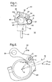
- FIG. 1 is a side view of a conventional variable valve actuating (VVA) mechanism;
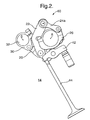
- FIG. 2 is a side view of one embodiment of a variable valve actuating mechanism of the present invention;
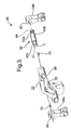
- FIG. 3 is an exploded view of the rocker, links and eccentric pin of Fig. 2;
- FIG. 4 is a partial, exploded view of an alternate embodiment of a VVA mechanism of the present invention;
- FIG. 5 is a side view of the VVA mechanism of Fig. 3; and
- FIG. 6 is a side view of the VVA mechanism of Fig. 4.
-
- Corresponding reference characters indicate corresponding parts throughout the several views. The exemplification set out herein illustrates one preferred embodiment of the invention, in one form, and such exemplification is not to be construed as limiting the scope of the invention in any manner.
- Referring now to the drawings, and particularly to Fig. 1, there is shown a conventional variable valve actuating (VVA) mechanism.
VVA mechanism 10 is configured as a control gear type VVA mechanism.VVA mechanism 10 is operably installed in relation to camshaft 12 ofengine 14, and includesframe 20,rocker 22,link 24a andoutput cam 26. - Camshaft 12 is driven to rotate by and in timed relation to a crankshaft (not shown) of
engine 14. Camshaft 12 rotates relative to central axis A thereof, and includescam lobe 28 that rotates as substantially one body withcamshaft 12.Frame 20 is pivotally associated withcamshaft 12 and is pivoted relative to central axis A bycontrol gear 30.Control gear 30 is disposed upon and pivoted bycontrol shaft 32, which has a central axis S that is substantially parallel relative to and spaced apart from centralaxis A. Frame 20 is pivotally coupled torocker 22 bypin 34.Rocker 22 carriesroller 36 that engagescam lobe 28 of camshaft 12. Rotation ofcam lobe 28 pivotally oscillatesroller 36 and, thus,rocker 22 in a generally radial direction toward and away from central axis A ofcamshaft 12. Rocker 22 is pivotally coupled to link 24a bypin 38, which transfers the pivotal oscillation ofrocker 22 to corresponding pivotal oscillation oflink 24a.Link 24a is pivotally coupled tooutput cam 26 bypin 40, which transfers the pivotal oscillation oflink 24a to corresponding pivotal oscillation ofoutput cam 26. The pivotal oscillation ofoutput cam 26 acts oncam follower 42, such as, for example, a direct acting cam follower or roller finger follower, that reciprocates and thereby opens and closesvalve 44 ofengine 14. - The angular orientation of
output cam 26 relative to central axis A and relative tocam follower 42 determines the portion of the lift profile ofoutput cam 26 that engagescam follower 42 asoutput cam 26 is pivotally oscillated. Thus, the angular orientation ofoutput cam 26 relative to central axis A and relative tocam follower 42 determines the lift profile ofvalve 44. As described above,frame 20 is pivoted relative to central axis A ofcamshaft 12 bycontrol gear 30 which, in turn, is pivoted bycontrol shaft 32.Control shaft 32 is placed in a predetermined angular position relative to central axis S thereof to thereby determine the angular position offrame 20 and, thus,output cam 26 relative to central axisA. Output cam 26 is thus placed in a predetermined angular orientation relative to central axis A which corresponds to a desired valve lift profile. -
Valve 44 is one of the valves, such as, for example, an intake valve, associated with a cylinder (not shown) ofengine 14. Each cylinder ofengine 14 includes, for example, two intake valves and two exhaust valves. Thus, although not shown in Fig. 1,VVA mechanism 10 may include a second link and output cam assembly that actuates one of the other valves of the same cylinder with whichvalve 44 is associated. - As described above, conventional variable valve actuating mechanisms do not enable the peak valve lifts of the valves actuated thereby to be relatively adjusted. Thus, there is likely to be a mismatch between the peak lift amounts of the valves actuated by the variable valve actuating mechanism. A relatively small mismatch, such as, for example, 0.5 mm, between the peak lifts of the valves within an engine cylinder can result in undesirable airflow characteristics within the cylinder, such as, for example, reduced tumble and/or excessive swirl. The present invention enables the relative peak lifts of the valves to be matched and/or set, thereby enabling adjustment of tumble and/or swirl within that cylinder. Furthermore, dimensional variation within a conventional variable valve actuating mechanisms results in a mismatch between valve lifts operating under relatively low peak lift operating conditions. The present invention enables the lifts of valves operating under such low peak lift operation conditions to be more closely matched, thereby improving engine stability and reducing rough engine idling.
- Referring now to Fig. 2, 3 and 5, one embodiment of a VVA mechanism of the present invention is shown.
VVA mechanism 60, although differently configured from VVA mechanism 10 (Fig. 1), includes several parts that correspond toVVA mechanism 10 in function and in design, and corresponding reference numbers are used to refer to those corresponding parts.VVA mechanism 60 includesframe 20,rocker 22 carrying roller 36 (Fig. 3),links output cam 26,control clamp 30 and control shaft 32 (shown in Fig. 2 only). - Generally,
VVA mechanism 60 substitutes an eccentric pin forpin 38 of VVA 10 (Fig. 1) to pivotally couplerocker 22 tolinks rocker 22 tolinks output cam 26 vialink 24a to be matched and/or set relative to the lift of a second valve (not shown) actuated by a second output cam (not shown) vialink 24b ofVVA mechanism 60. - As best shown in Figs. 3 and 5,
VVA mechanism 60 includeseccentric pin 62 that pivotally couples togetherrocker 22 andlinks Eccentric pin 62 has a first centerline C and a second centerline C' that is substantially parallel relative to and spaced apart from centerlineC. Eccentric pin 62 further includespin sections eccentric pin section 62c. -
Pin section 62a extends axially from one side ofpin section 62b, and bothpin section 62a andsection 62b are substantially concentric relative to each other and relative to centerlineC. Eccentric section 62c is substantially concentric relative to centerline C' and is, thus, eccentric relative to centerline C andpin sections pin section 62a andeccentric section 62c define tool-accepting feature 64 (Fig. 3, shown inpin section 62a), such as, for example, a hexagonal socket. Tool-acceptingfeature 64 accepts a tool, such as, for example, an Allen wrench or other type of wrench, to facilitate rotation and/or adjustment of the angular orientation ofeccentric pin 62 when in the installed or use position. - As stated above,
eccentric pin 62 pivotally couples togetherrocker 22 andlinks pin section 62a is received withinorifice 66 formed inlink 24b,eccentric section 62c is received withinorifice 66 formed inlink 24a, andpin section 62b is received withinbore 68 formed throughrocker 22. One of retaining means 72 (two shown), such as, for example, set screws, retainseccentric pin 62 in position withinbore 68 andorifice 66, and retains centerline C' in a desired angular position or relative orientation relative to centerline C. It is to be understood that two retaining means 72 are shown only to illustrate two possible locations therefor. The use of both retaining means 72 is not required and, furthermore, would cause slippage between and undesirable wear of retaining means 72 and/oreccentric pin 62. -
Link 24a is pivotally coupled by pin 40 (Fig. 5) tooutput cam 26, whereaslink 24b is pivotally coupled to the second output cam (not shown) ofVVA mechanism 60 by a second pin (not shown). - In use, the nominal lift and/or the nominal lift profile of the valves associated with
VVA mechanism 60 is set by the angular position of control shaft 32 (Fig. 2) relative to central axis S thereof, as is known in the art. Generally,VVA mechanism 60 enables the peak lift of the valve actuated byoutput cam 26 to be matched with and/or set relative to the peak lift of the valve (not shown) actuated by the second output cam (not shown) ofVVA mechanism 60 by pivotingeccentric pin 62 relative to centerline C. More particularly, pivotingeccentric pin 62 relative to centerline C pushes and/or pulls onlink 24a to thereby pivotoutput cam 26 relative to central axis A.Pivoting output cam 26 relative to central axis A, in turn, changes the portion of the lift profile ofoutput cam 26 that engages cam follower 42 (Figs. 1 and 2) associated therewith and which transfers pivotal oscillation ofoutput cam 26 to actuation of the associated valve (not shown). The portion of the lift profile ofoutput cam 26 that engages the cam follower determines the amount of lift imparted to the associated valve. Thus, by pivotingeccentric pin 62 the peak lift of the valve associated withoutput cam 26 is adjusted relative to the peak lift of a second valve that is actuated by a second output cam ofVVA mechanism 60. - The effect of pivoting
eccentric pin 62 on the angular orientation ofoutput cam 26 is hereinafter discussed in detail. Referring to Fig. 5, angle α is defined between respective lines drawn from centerlines C and C' to central axis A ofcamshaft 12. With angle α equal to zero degrees,output cam 26 occupies a base angular orientation B relative to central axis A ofcamshaft 12.Output cam 26 in base angular orientation B imparts substantially the desired nominal lift to the associated valve, since the position ofoutput cam 26 is substantially unchanged from that established bycontrol shaft 32. Angle is defined as the degree to whichoutput cam 26 has been pivoted from the base angular orientation B thereof relative to central axis A and into a new or adjusted base angular orientation. Generally, pivotingeccentric pin 62 relative to the centerline C varies angle α. A change in angle α results in a corresponding change in angle and, thus, a change in the angular orientation ofoutput cam 26 relative to central axis A. - More particularly, as
eccentric pin 62 is pivoted centerline C' andeccentric section 62c (Fig. 3) pivot relative to centerline C thus causing angle α to vary. The pivoting ofeccentric section 62c pushes and/or pullslink 24a thereby pivotingoutput cam 26 relative to central axis A and varying angle . Angle α is varied by rotation ofeccentric pin 62 from a positive or clockwise maximum value α MAX to a negative or counterclockwise maximum value referred to hereinafter as αMIN (not shown). Similarly, angle is varied by the rotation ofeccentric pin 62 from a positive or clockwise maximum MAX to a negative or counterclockwise maximum hereinafter referred to as MIN (not shown). - Each of angles α and are approximately equal to zero degrees with
eccentric pin 62 oriented such that centerlines C and C' are approximately coplanar with central axis A, regardless of whether centerline C or centerline C' is disposed most proximate to central axis A. Thus, angles α and are approximately equal to zero degrees witheccentric pin 62 in one of the two aforementioned angular orientations. With angles α and equal to zero degrees,output cam 26 is oriented in base angular orientation B. Thus, the lift imparted byoutput cam 26 to the associated valve is approximately the nominal lift as established bycontrol shaft 32. - Angle α is maximized in the clockwise direction to αMAX by pivoting
eccentric pin 62 such that centerlines C and C' are disposed in a generally coplanar manner with the central axis (not referenced) ofpin 40 with centerline C' being disposed most proximate to pin 40. Pivotingeccentric pin 62 to place angle α at αMAX displaces or pushes link 24a in a clockwise direction, and thereby causesoutput cam 26 to pivot relative to central axis A in a clockwise direction such that angle is also maximized in a clockwise direction to angle MAX . Thus,output cam 26 is oriented in a new or adjusted base angular orientation B MAX by pivotingeccentric pin 62 such that centerlines C and C' are disposed in a generally coplanar manner relative to the central axis (not referenced) ofpin 40 with centerline C' being disposed most proximate to pin 40. - Adjusted base angular orientation B MAX represents the maximum clockwise angular orientation of
output cam 26, i.e.,output cam 26 is maximally pivoted in a clockwise direction relative to base angular orientation B.Orienting output cam 26 in adjusted base orientation B MAX disposes a greater portion of the low lift or constant radius portion ofoutput cam 26 within the pivotal oscillatory range ofoutput cam 26. Asoutput cam 26 is pivotally oscillated from adjusted base orientation B MAX , more of the low-lift portion of the lift profile ofoutput cam 26 engages the cam follower relative to the portion that engages the cam follower whenoutput cam 26 is pivotally oscillated from base orientation B. Thus, the lift imparted to the associated valve whenoutput cam 26 is pivotally oscillated from adjusted base orientation B MAX is maximally reduced relative to the nominal lift that is imparted by pivotally oscillatingoutput cam 26 from base orientation B. - Angle α is maximized in the counterclockwise direction to αMIN (not shown) by pivoting
eccentric pin 62 such that centerlines C and C' are disposed approximately coplanar with the central axis (not referenced) ofpin 40 with centerline C being disposed most proximate to pin 40. Pivotingeccentric pin 62 to place angle α at αMIN displaces or pullslink 24a in a counter-clockwise direction and thereby causesoutput cam 26 to pivot relative to central axis A in a counter-clockwise direction such that angle is also maximized in a counter-clockwise direction to angle MIN (not shown). Thus,output cam 26 is oriented in a new or adjusted base angular orientation B MIN (not shown) by pivotingeccentric pin 62 such that centerlines C and C' are disposed approximately coplanar relative to the central axis (not referenced) ofpin 40 with centerline C being disposed most proximate to pin 40. - Adjusted base orientation B MIN represents the maximum counterclockwise base position of
output cam 26, i.e.,output cam 26 is maximally pivoted in a counter-clockwise direction relative to base angular orientation B.Orienting output cam 26 in adjusted base orientation B MIN disposes a greater portion of the higher lift profile ofoutput cam 26 within the pivotal oscillation range ofoutput cam 26. Asoutput cam 26 is pivotally oscillated from adjusted base orientation B MIN, more of the high lift portion of the lift profile ofoutput cam 26 engages the cam follower relative to the portion that engages the cam follower whenoutput cam 26 is pivotally oscillated from adjusted base orientation B MIN. Thus, the lift imparted to the associated valve whenoutput cam 26 is pivotally oscillated from adjusted base position B MIN is maximally increased relative to the nominal lift that is imparted by pivotally oscillatingoutput cam 26 from base angular orientation B. - It should be particularly noted that the angular orientation of
eccentric pin 62 and, thus, the angular position of centerline C' relative to centerline C are variable through three hundred and sixty degrees. Therefore,VVA 60 enables the substantially continuous adjustment of the lift of the valve associated withoutput cam 26. The lift of the associated valve is minimized, i.e., adjusted to a peak value of the nominal lift minus an adjustment value, withoutput cam 26 oriented in adjusted base position B MAX. Conversely, the lift of the associated valve is maximized, i.e., adjusted to a peak value of the nominal lift plus an adjustment value, withoutput cam 26 oriented in adjusted base position B MIN. - Pivoting
eccentric pin 62 in either a clockwise or counterclockwise direction withoutput cam 26 in adjusted base angular orientation B MAX, wherein the lift is minimized, increases the lift imparted to the associated valve. More particularly, such a pivoting ofeccentric pin 62 displaces or pullslink 24a thereby causingoutput cam 26 to pivot in a counterclockwise direction. Asoutput cam 26 pivots in a counterclockwise direction from adjusted base angular orientation B MAX , the high lift portion thereof is brought angularly more proximate to the cam follower. Thus, asoutput cam 26 is pivotally oscillated more of the high lift portion of the lift profile ofoutput cam 26 engages the cam follower relative to adjusted base angular orientation B MAX. - The counterclockwise pivoting of
output cam 26, and thus the increase in lift imparted to the associated valve, continues untileccentric pin 62 is pivoted in either direction approximately one-hundred eighty degrees (180°) from adjusted base angular orientation B MAX. Pivotingeccentric pin 62 approximately 180° in either direction from adjusted base angular orientation B MAX orientseccentric pin 62 such that centerlines C and C' are substantially coplanar relative to the central axis ofpin 40 with centerline C most proximate to pin 40. Thus,output cam 26 is placed in adjusted base angular orientation B MIN wherein the lift imparted to the valve is maximized. - Conversely, pivoting
eccentric pin 62 in either a clockwise or counterclockwise direction withoutput cam 26 in adjusted base angular orientation B MIN , wherein the lift is maximized, decreases the lift imparted to the associated valve. Such a pivoting ofeccentric pin 62 displaces or pushes link 24a in a clockwise direction thereby causingoutput cam 26 to pivot in a clockwise direction. Asoutput cam 26 pivots in a clockwise direction from adjusted base angular orientation B MIN , the low lift portion thereof is brought angularly more proximate to the cam follower. Thus, asoutput cam 26 is pivotally oscillated more of the low lift portion of the lift profile ofoutput cam 26 engages the cam follower relative to adjusted base angular orientation B MAX . The clockwise pivoting ofoutput cam 26, and thus the decrease in lift imparted to the associated valve, continues untileccentric pin 62 is pivoted in either direction approximately 180° from adjusted base angular orientation B MIN. - As stated above, the relative eccentricity of centerlines C and C' is from approximately 0.001 mm to approximately 1.0 mm. Centerlines C and C' can be positioned such that they are each substantially coplanar relative to the central axis of
pin 40 in two possible orientations, i.e., one with centerline C' most proximate to pin 40 and the other with centerline C most proximate to pin 40. Thus, for example, with a given eccentricity of 1.0mm the eccentricity ofeccentric pin 62 is continuously adjustable from ±1.0 mm relative to (i.e., toward and away from)pin 40. The corresponding range over whichoutput cam 26 is pivoted relative to central axis A, and thus the range over which the lift of the valve associated withoutput cam 26 is adjusted, is dependent upon the configuration of the particular VVA mechanism with whicheccentric pin 62 is used. - Adjustment of the angular orientation of
eccentric pin 62 is facilitated by, for example, inserting a wrench or other tool into, tool-acceptingfeature 64. Witheccentric pin 62 in the desired angular orientation, either one of retaining means 72 is installed and tightened to secure and retaineccentric pin 62 in the desired orientation and position withinorifices 66 and bore 68. Thus, the lift of the valve associated withoutput cam 26 is adjusted from a nominal value to an adjusted valve relative to the lift of the second valve actuated by the second output cam ofVVA mechanism 60. The relative lifts of the valve actuated byoutput cam 26 and the second output cam are set and/or calibrated to achieve, for example, matching peak lifts or a desirable difference in peak lifts to create favorable air flow characteristics within the cylinder. - Referring now to Figs. 4 and 6, a second exemplary embodiment of a VVA mechanism of the present invention is shown. Generally,
VVA mechanism 80 substitutes an eccentric pin forpin 40 of VVA 10 (Fig. 1) topivotally couple links output cam 26. The eccentric pin enables the lift of a first valve (not shown) actuated byoutput cam 26 vialink 24a to be matched with and/or set relative to the lift of a second valve (not shown) actuated by a second output cam vialink 24b (not shown) ofVVA mechanism 80. -
VVA mechanism 80 includeseccentric pin 82 having centerlines C and C',pin sections eccentric section 82c. Centerline C is substantially parallel relative to and spaced apart from centerline C'.Pin section 82a extends axially from one side ofeccentric section 82c, andpin section 82b extends axially from an opposite end ofeccentric section 82c.Pin sections C. Eccentric section 82c is substantially concentric relative to centerline C' and is, thus, eccentric relative to centerline C andpin sections -
Eccentric pin 82 pivotally couples link 24a withoutput cam 26.Pin sections orifices 84 formed inlink 24a, andeccentric section 82c is received withinorifice 86 formed inoutput cam 26. Retaining means 72, such as, for example, a set screw, retainseccentric pin 62 withinorifice 86 and further retains centerline C' and centerline C in a desired angular position and/or relative angular orientation. Collars orbushings 88 are inserted into a respective one oforifices 84 and over a corresponding one ofpin sections - In use,
VVA mechanism 80 operates in a generally similar manner toVVA mechanism 60 and enables the lift of the valve associated withoutput cam 26 to be matched with and/or set relative to the lift of a second valve actuated by a second output cam ofVVA mechanism 80. The nominal lift and/or the nominal lift profile of the valves associated withVVA mechanism 60 is set by the angular position of control shaft 32 (Fig. 2) relative to central axis S thereof, as is known in the art. - The effect of pivoting
eccentric pin 82 on the angular orientation ofoutput cam 26 is hereinafter discussed in detail. Referring to Fig. 6, angle α is varied by rotation ofeccentric pin 82 from a positive or clockwise maximum value αMAX to a negative or counter-clockwise maximum value αMIN (not shown). Similarly, angle is varied by the rotation ofeccentric pin 82 from a positive or clockwise maximum MAX to a negative or counterclockwise maximum MIN (not shown). - Each of angles α and are approximately equal to zero degrees with
eccentric pin 82 oriented such that centerlines C and C' are approximately coplanar with central axis A, regardless of whether centerline C or centerline C' is disposed most proximate to central axis A. Thus, angles α and are approximately equal to zero degrees witheccentric pin 82 in one of the two aforementioned angular orientations. With angles α and equal to zero degrees,output cam 26 is oriented in base angular orientation B. Thus, the lift imparted byoutput cam 26 to the associated valve is approximately the nominal lift as established bycontrol shaft 32. - Angle α is maximized in the clockwise direction to αMAX by pivoting
eccentric pin 82 such that centerlines C and C' are disposed in a generally coplanar manner with the central axis (not referenced) ofpin 38 with centerline C being disposed most proximate to pin 38. Pivotingeccentric pin 82 to place angle α at αMAX displaces or pushesoutput cam 26 in a clockwise direction, and thereby causesoutput cam 26 to pivot relative to central axis A in a clockwise direction such that angle is also maximized in a clockwise direction to angle MAX. Thus,output cam 26 is oriented in adjusted base angular orientation B MAX witheccentric pin 82 oriented such that centerlines C and C' are disposed in a generally coplanar manner relative to the central axis (not referenced) ofpin 30 with centerline C being disposed most proximate to pin 38. - Adjusted base position B MAX represents the maximum clockwise base position of
output cam 26, i.e.,output cam 26 is maximally pivoted in a clockwise direction relative to base angular orientation B.Orienting output cam 26 in adjusted base orientation B MAX disposes a greater portion of the low lift or constant radius portion ofoutput cam 26 within the pivotal oscillatory range ofoutput cam 26. Asoutput cam 26 is pivotally oscillated from adjusted base orientation B MAX , more of the low-lift portion of the lift profile ofoutput cam 26 engages the cam follower relative to the portion that engages the cam follower whenoutput cam 26 is pivotally oscillated from base position B. Thus, the lift imparted to the associated valve whenoutput cam 26 is pivotally oscillated from adjusted base orientation B MAX is maximally reduced relative to the nominal lift that is imparted by pivotally oscillatingoutput cam 26 from base position B. - Angle α is maximized in the counterclockwise direction to αMIN (not shown) by pivoting
eccentric pin 82 such that centerlines C and C' are disposed approximately coplanar with the central axis (not referenced) ofpin 38 with centerline C' being disposed most proximate to pin 30. Pivotingeccentric pin 82 to place angle α at αMIN displaces or pullsoutput cam 26 in a counter-clockwise direction such that angle is also maximized in a counter-clockwise direction to angle MIN (not shown). Thus,output cam 26 is oriented in adjusted base angular orientation B MIN (not shown). - Adjusted base orientation B MIN represents the maximum counterclockwise base position of
output cam 26, i.e.,output cam 26 is maximally pivoted in a counter-clockwise direction relative to base angular orientation B.Orienting output cam 26 in adjusted base orientation B MIN disposes a greater portion of the higher lift profile ofoutput cam 26 within the pivotal oscillation range ofoutput cam 26. Asoutput cam 26 is pivotally oscillated from adjusted base orientation B MIN, more of the high lift portion of the lift profile ofoutput cam 26 engages the cam follower relative to the portion that engages the cam follower whenoutput cam 26 is pivotally oscillated from adjusted base orientation B MIN. Thus, the lift imparted to the associated valve whenoutput cam 26 is pivotally oscillated from adjusted base position B MIN is maximally increased relative to the nominal lift that is imparted by pivotally oscillatingoutput cam 26 from base angular orientation B. - It should be particularly noted that, substantially similar to
VVA mechanism 60, the angular orientation ofeccentric pin 82 ofVVA mechanism 80 and, thus, the angular orientation of centerline C' relative to centerline C are variable through three hundred and sixty degrees. Accordingly, the angular orientation ofoutput cam 26 is substantially continuously adjustable from adjusted base orientation B MIN to adjusted base orientation B MAX . Therefore, the lift of the valve associated withoutput cam 26 is also substantially continuously adjustable from a maximally increased lift to a maximally decreased lift relative to the nominal lift, as determined by the angular orientation ofcontrol shaft 32. The lift of the valve associated withoutput cam 26 is thereby set or relative to or calibrated with the lift of the valve associated with the second output cam ofVVA mechanism 80. - It should further be particularly noted that, substantially similar to
VVA mechanism 60, pivotingeccentric pin 82 in either a clockwise or counterclockwise direction withoutput cam 26 in adjusted base angular orientation B MAX, wherein the lift is minimized, increases the lift imparted to the associated valve. Conversely, and still substantially similar toVVA mechanism 60, pivotingeccentric pin 82 in either a clockwise or counterclockwise direction withoutput cam 26 in adjusted base angular orientation B MIN, wherein the lift is maximized, decreases the lift imparted to the associated valve. - In the embodiments shown, an eccentric pin couples together at least one of the links with one of a rocker or corresponding output cam. However, it is to be understood that the VVA of the present invention can be alternately configured, such as, for example, with an eccentric pin coupling at least one of the links with each of a corresponding output cam and the rocker.
- In the embodiments shown, the eccentric pins are shown in conjunction with a particularly configured VVA mechanism. However, it is to be understood that the VVA mechanism of the present invention can be alternately configured, such as, for example, as a belt-driven VVA mechanism or any other suitable type of VVA mechanism, and still effectively adjust the amount of lift imparted to the associated valve.
- In the embodiments shown, an eccentric pin is used to pivotally couple together one of two links with an output cam or one of two links with a rocker. However, it is to be understood that the present invention can be alternately configured, such as, for example, with a dual or integrated link (rather than two separate links) that is pivotally coupled by an eccentric pin to one of a pair of output cams or to a corresponding separate or an integrated rocker.
- In the embodiments shown, retaining means, such as a set screw and/or a set screw and collar assembly, are used to retain the eccentric pin in the desired location and angular orientation. However, it is to be understood that the present invention can be alternately configured with various other retaining means.
- In the embodiment shown, an eccentric pin is used to pivotally couple together one of a link and an output cam or a link and a rocker. However, it is to be understood that the present invention can be alternately configured, such as, for example, using an eccentric pin to pivotally couple together each link and rocker, and each link and corresponding output cam.
- While this invention has been described as having a preferred design, the present invention can be further modified within the spirit and scope of this disclosure. This application is therefore intended to cover any variations, uses, or adaptations of the present invention using the general principles disclosed herein. Further, this application is intended to cover such departures from the present disclosure as come within the known or customary practice in the art to which this invention pertains and which fall within the limits of the appended claims.
Claims (19)
- A variable valve actuating (VVA) mechanism 60,80, comprising:wherein at least one of said first and second pins 38, 40 is an eccentric pin 62,82.a frame member 20 configured for being pivoted relative to a central axis A that is at least one of substantially parallel relative to and coaxial with a central axis A of an input shaft 12;a rocker 22 having a first end and a second end, said first end pivotally coupled to said frame;a link 24a having a first end and a second end;a first pin 38 pivotally coupling said first end of said link to said second end of said rocker;an output cam 26;a second pin 40 pivotally coupling said output cam to said second end of said link;
- The VVA mechanism 60 of claim 1, wherein said first pin 38 comprises an eccentric pin 62.
- The VVA mechanism 60 of claim 2, wherein said first pin 62 comprises:a first pin portion 62a having a first centerline C, said first pin portion being substantially concentric relative to said first centerline;a second pin portion 62b extending axially from said first pin portion 62a, said second pin portion being substantially concentric relative to said second centerline C; andan eccentric portion 62c extending axially from said second pin portion 62b, said eccentric portion having a second centerline C', said eccentric portion 62c being substantially concentric relative to said second centerline C' and eccentric relative to said first centerline C, said first centerline being substantially parallel with and spaced apart from said second centerline.
- The VVA mechanism 60 of claim 3, wherein said second end of said rocker 22 defines a rocker bore 68 therethrough, said first end of said link defines a link bore 66 therethrough, said eccentric portion 62c being disposed at least partially within said link bore 66, said second pin portion 62b being disposed at least partially within said rocker bore 68.
- The VVA mechanism 60 of claim 4, wherein said first centerline C and said second centerline C' are spaced apart from each other from approximately 0.001 mm to approximately 1.5 mm.
- The VVA mechanism 80 of claim 1, wherein said second pin 40 comprises an eccentric pin 82.
- The VVA mechanism 80 of claim 6, wherein said second pin comprises:an eccentric portion 82c having a first centerline C', said eccentric portion being substantially concentric relative to said first centerline C'; andpin portions 82a,82b extending axially in each direction from said eccentric portion 82c, said pin portions having a second centerline C and being substantially concentric relative thereto, said eccentric portion 82c being eccentric relative to said second centerline C, said second centerline C being substantially parallel relative to and spaced apart from said first centerline C'.
- The VVA mechanism 80 of claim 7, wherein said second end of said link defines opposing link orifices 84 therethrough, said output cam 26 defines a cam orifice 86 therein, said eccentric portion 82c being disposed within said cam orifice 86, said pin portions 82a,82b being disposed at least partially within a respective one of said link orifices 84.
- The VVA mechanism 80 of claim 7, wherein said first centerline C' and said second centerline C are spaced apart from each other from approximately 0.015 mm to approximately 1.5 mm.
- The VVA mechanism 60,80 of claim 1, further comprising retaining means 72 associated with each said at least one eccentric pin.
- The VVA mechanism 60,80 of claim 10, wherein said retaining means 72 comprises a set screw.
- The VVA mechanism 60,80 of claim 1, wherein said at least one eccentric pin includes a tool-accepting feature 64.
- The VVA mechanism 60,80 of claim 12, wherein said tool-accepting feature comprises a recessed socket defined by an end of said eccentric pin.
- A method for setting the lift of a first valve 44 relative to a second valve 44 of an engine cylinder, at least said first valve being actuated by a variable valve actuating (VVA) mechanism 60,80, said method comprising:ascertaining the maximum lift of the second valve;determining the maximum lift of the first valve; andpivoting an eccentric pin 62,82 of the VVA mechanism to thereby pivot an output cam thereof from a base angular orientation to an adjusted base angular orientation, thereby one of increasing and decreasing the lift imparted to the first valve by the VVA mechanism.
- The method of claim 14, wherein said pivoting step comprises pivoting an eccentric pin 62 that pivotally couples together a rocker 22 and a link 24a of the VVA mechanism 60.
- The method of claim 14, wherein said pivoting step comprises pivoting an eccentric pin 82 that pivotally couples together a link 24a and an output cam 26 of the VVA mechanism 80.
- The method of claim 14, wherein said pivoting step comprises engaging a tool-accepting feature of the eccentric pin with a corresponding tool.
- The method of claim 17, wherein said tool-accepting feature comprises a socket defined by an end of the eccentric pin.
- An internal combustion engine14, said engine having at least one cylinder, at least four valves 44 operably associated with said cylinder, said engine comprising:wherein at least one of said first and second pins 38,40 is an eccentric pin 62,82.a variable valve actuating mechanism 60,80 actuating at least one of said valves, said variable valve mechanism including:a frame member 20 configured for being pivoted relative to a central axis A that is one of substantially parallel relative to and coaxial with a central axis A of a camshaft 12 of said engine 14;a rocker 22 having a first end and a second end, said first end pivotally coupled to said frame;a link 24a having a first end and a second end;a first pin 38 pivotally coupling said first end of said link to said second end of said rocker;an output cam 26;a second pin 40 pivotally coupling said output cam to said second end of said link;
Applications Claiming Priority (2)
| Application Number | Priority Date | Filing Date | Title |
|---|---|---|---|
| US10/080,214 US6736096B2 (en) | 2002-02-21 | 2002-02-21 | Method and apparatus for setting valve lift within a cylinder |
| US80214 | 2002-02-21 |
Publications (2)
| Publication Number | Publication Date |
|---|---|
| EP1338765A2 true EP1338765A2 (en) | 2003-08-27 |
| EP1338765A3 EP1338765A3 (en) | 2007-12-19 |
Family
ID=27660329
Family Applications (1)
| Application Number | Title | Priority Date | Filing Date |
|---|---|---|---|
| EP03075284A Withdrawn EP1338765A3 (en) | 2002-02-21 | 2003-01-30 | Method and apparatus for setting valve lift within a cylinder |
Country Status (2)
| Country | Link |
|---|---|
| US (1) | US6736096B2 (en) |
| EP (1) | EP1338765A3 (en) |
Cited By (4)
| Publication number | Priority date | Publication date | Assignee | Title |
|---|---|---|---|---|
| DE10342075A1 (en) * | 2003-09-10 | 2005-06-16 | Rolf Jung | Fully variable globe valve control of an internal combustion engine |
| WO2006054147A1 (en) * | 2004-11-17 | 2006-05-26 | Nissan Motor Co., Ltd. | Valve mechanism lift adjustment device and method |
| EP1956201A3 (en) * | 2007-02-06 | 2008-08-20 | Mazda Motor Corporation | An adjustable valve drive device of an engine and mounting method therefore |
| EP1574679A3 (en) * | 2004-03-12 | 2009-02-25 | Nissan Motor Co., Ltd. | Adjusting mechanism and adjusting method of valve-lift amount of internal combustion engine |
Families Citing this family (5)
| Publication number | Priority date | Publication date | Assignee | Title |
|---|---|---|---|---|
| US6877465B1 (en) * | 2003-12-19 | 2005-04-12 | Delphi Technologies, Inc. | Method and apparatus for adjusting the angular position of a collar on a shaft |
| US6971355B2 (en) | 2004-03-29 | 2005-12-06 | Borgwarner Inc. | Variable lift and duration device for poppet valves |
| US7047957B1 (en) | 2005-04-25 | 2006-05-23 | Delphi Technologies, Inc. | Method and apparatus for monitoring a multiple step valve lifter |
| US8640660B2 (en) * | 2011-03-10 | 2014-02-04 | Jesper Frickmann | Continuously variable valve actuation apparatus for an internal combustion engine |
| US9133735B2 (en) | 2013-03-15 | 2015-09-15 | Kohler Co. | Variable valve timing apparatus and internal combustion engine incorporating the same |
Citations (1)
| Publication number | Priority date | Publication date | Assignee | Title |
|---|---|---|---|---|
| US5937809A (en) | 1997-03-20 | 1999-08-17 | General Motors Corporation | Variable valve timing mechanisms |
Family Cites Families (11)
| Publication number | Priority date | Publication date | Assignee | Title |
|---|---|---|---|---|
| US4475489A (en) * | 1981-05-27 | 1984-10-09 | Honda Giken Kogyo Kabushiki Kaisha | Variable valve timing device for an internal combustion engine |
| SE464367B (en) * | 1987-02-26 | 1991-04-15 | Volvo Ab | VALVE MECHANISM CONTROLS A DISTRICT VALVE |
| GB9003603D0 (en) * | 1990-02-16 | 1990-04-11 | Lotus Group Plc | Cam mechanisms |
| DE4425560A1 (en) * | 1994-07-20 | 1996-01-25 | Schuler Pressen Gmbh & Co | Press with gripper rails |
| US5860328A (en) * | 1995-06-22 | 1999-01-19 | Chrysler Corporation | Shaft phase control mechanism with an axially shiftable splined member |
| JPH108927A (en) * | 1996-06-26 | 1998-01-13 | Unisia Jecs Corp | Intake and exhaust valve drive control device for internal combustion engine |
| JP3924078B2 (en) * | 1998-05-21 | 2007-06-06 | 株式会社日立製作所 | Variable valve operating device for internal combustion engine |
| US6588387B2 (en) * | 1998-10-20 | 2003-07-08 | Eaton Corporation | Rocker arm device for simultaneous control of valve lift and relative timing in a combustion engine |
| JP4253109B2 (en) * | 2000-08-31 | 2009-04-08 | 日産自動車株式会社 | Variable valve operating device for internal combustion engine |
| US6568361B2 (en) * | 2000-09-21 | 2003-05-27 | Unisia Jecs Corporation | Valve operating device for internal combustion engines |
| US6439178B1 (en) * | 2001-01-05 | 2002-08-27 | Delphi Technologies, Inc. | Mechanical lash adjuster apparatus for an engine cam |
-
2002
- 2002-02-21 US US10/080,214 patent/US6736096B2/en not_active Expired - Fee Related
-
2003
- 2003-01-30 EP EP03075284A patent/EP1338765A3/en not_active Withdrawn
Patent Citations (1)
| Publication number | Priority date | Publication date | Assignee | Title |
|---|---|---|---|---|
| US5937809A (en) | 1997-03-20 | 1999-08-17 | General Motors Corporation | Variable valve timing mechanisms |
Cited By (7)
| Publication number | Priority date | Publication date | Assignee | Title |
|---|---|---|---|---|
| DE10342075A1 (en) * | 2003-09-10 | 2005-06-16 | Rolf Jung | Fully variable globe valve control of an internal combustion engine |
| EP1574679A3 (en) * | 2004-03-12 | 2009-02-25 | Nissan Motor Co., Ltd. | Adjusting mechanism and adjusting method of valve-lift amount of internal combustion engine |
| WO2006054147A1 (en) * | 2004-11-17 | 2006-05-26 | Nissan Motor Co., Ltd. | Valve mechanism lift adjustment device and method |
| CN100467835C (en) * | 2004-11-17 | 2009-03-11 | 日产自动车株式会社 | Valve lift adjusting device and method and valve lift adjusting method |
| US7562643B2 (en) | 2004-11-17 | 2009-07-21 | Nissan Motor Co., Ltd. | Valve mechanism lift adjustment device and method |
| EP1956201A3 (en) * | 2007-02-06 | 2008-08-20 | Mazda Motor Corporation | An adjustable valve drive device of an engine and mounting method therefore |
| US7739991B2 (en) | 2007-02-06 | 2010-06-22 | Mazda Motor Corporation | Adjustable valve drive device of engine |
Also Published As
| Publication number | Publication date |
|---|---|
| US20030154940A1 (en) | 2003-08-21 |
| EP1338765A3 (en) | 2007-12-19 |
| US6736096B2 (en) | 2004-05-18 |
Similar Documents
| Publication | Publication Date | Title |
|---|---|---|
| US7562643B2 (en) | Valve mechanism lift adjustment device and method | |
| US6615775B2 (en) | Variable valve operating system of internal combustion engine enabling variation of valve-lift characteristic and phase | |
| US6041746A (en) | Variable valve actuation apparatus | |
| JP3680863B2 (en) | Valve mechanism for internal combustion engine | |
| EP1873362B1 (en) | Variable valve mechanism | |
| EP1318286A2 (en) | Engine control system of internal combustion engine with variable compression ratio mechanism and exhaust-gas recirculation control system | |
| US6736096B2 (en) | Method and apparatus for setting valve lift within a cylinder | |
| JPH0893515A (en) | Switching control method of valve operating characteristics and air-fuel ratio in internal combustion engine | |
| JP2006274951A (en) | 4-cycle spark ignition engine | |
| US6988473B2 (en) | Variable valve actuation mechanism having an integrated rocker arm, input cam follower and output cam body | |
| JP4402798B2 (en) | Control device for internal combustion engine | |
| JP2002256905A (en) | Intake control device for internal combustion engine | |
| US7814873B2 (en) | Variable valve operating device and valve opening amount adjustment method | |
| EP1300551A3 (en) | Variable valve operating system of internal combustion engine enabling variation of valve-lift characteristic | |
| US6868811B2 (en) | Frameless variable valve actuation mechanism | |
| JPH06146829A (en) | Switching control device for engine with valve variable driving mechanism | |
| US20110120398A1 (en) | Valve Control Apparatus for Internal Combustion Engine | |
| US20080087242A1 (en) | Valve mechanism for multi-cylinder internal combustion engine and assembling method of valve mechanism therefor | |
| US6439178B1 (en) | Mechanical lash adjuster apparatus for an engine cam | |
| US7942123B2 (en) | Variable valve system for internal combustion engine | |
| US20030101951A1 (en) | Extended duration cam lobe for variable valve actuation mechanism | |
| US6655330B2 (en) | Offset variable valve actuation mechanism | |
| KR101465634B1 (en) | Continuously variable valve lift actuator of engine | |
| US20030172886A1 (en) | Variable valve actuation mechanism having partial wrap bearings for output cams and frames | |
| JP4661647B2 (en) | Control device for variable valve mechanism |
Legal Events
| Date | Code | Title | Description |
|---|---|---|---|
| PUAI | Public reference made under article 153(3) epc to a published international application that has entered the european phase |
Free format text: ORIGINAL CODE: 0009012 |
|
| AK | Designated contracting states |
Designated state(s): AT BE BG CH CY CZ DE DK EE ES FI FR GB GR HU IE IT LI LU MC NL PT SE SI SK TR |
|
| AX | Request for extension of the european patent |
Extension state: AL LT LV MK RO |
|
| PUAL | Search report despatched |
Free format text: ORIGINAL CODE: 0009013 |
|
| AK | Designated contracting states |
Kind code of ref document: A3 Designated state(s): AT BE BG CH CY CZ DE DK EE ES FI FR GB GR HU IE IT LI LU MC NL PT SE SI SK TR |
|
| AX | Request for extension of the european patent |
Extension state: AL LT LV MK RO |
|
| AKX | Designation fees paid | ||
| REG | Reference to a national code |
Ref country code: DE Ref legal event code: 8566 |
|
| STAA | Information on the status of an ep patent application or granted ep patent |
Free format text: STATUS: THE APPLICATION IS DEEMED TO BE WITHDRAWN |
|
| 18D | Application deemed to be withdrawn |
Effective date: 20080620 |