EP1338679A1 - Metallic sliding member, piston for internal combustion engine, method of surface-treating these, and apparatus therefor - Google Patents
Metallic sliding member, piston for internal combustion engine, method of surface-treating these, and apparatus therefor Download PDFInfo
- Publication number
- EP1338679A1 EP1338679A1 EP01983814A EP01983814A EP1338679A1 EP 1338679 A1 EP1338679 A1 EP 1338679A1 EP 01983814 A EP01983814 A EP 01983814A EP 01983814 A EP01983814 A EP 01983814A EP 1338679 A1 EP1338679 A1 EP 1338679A1
- Authority
- EP
- European Patent Office
- Prior art keywords
- piston
- molybdenum disulfide
- sliding
- powder
- dimples
- Prior art date
- Legal status (The legal status is an assumption and is not a legal conclusion. Google has not performed a legal analysis and makes no representation as to the accuracy of the status listed.)
- Granted
Links
Images





Classifications
-
- C—CHEMISTRY; METALLURGY
- C23—COATING METALLIC MATERIAL; COATING MATERIAL WITH METALLIC MATERIAL; CHEMICAL SURFACE TREATMENT; DIFFUSION TREATMENT OF METALLIC MATERIAL; COATING BY VACUUM EVAPORATION, BY SPUTTERING, BY ION IMPLANTATION OR BY CHEMICAL VAPOUR DEPOSITION, IN GENERAL; INHIBITING CORROSION OF METALLIC MATERIAL OR INCRUSTATION IN GENERAL
- C23C—COATING METALLIC MATERIAL; COATING MATERIAL WITH METALLIC MATERIAL; SURFACE TREATMENT OF METALLIC MATERIAL BY DIFFUSION INTO THE SURFACE, BY CHEMICAL CONVERSION OR SUBSTITUTION; COATING BY VACUUM EVAPORATION, BY SPUTTERING, BY ION IMPLANTATION OR BY CHEMICAL VAPOUR DEPOSITION, IN GENERAL
- C23C24/00—Coating starting from inorganic powder
- C23C24/02—Coating starting from inorganic powder by application of pressure only
- C23C24/04—Impact or kinetic deposition of particles
-
- F—MECHANICAL ENGINEERING; LIGHTING; HEATING; WEAPONS; BLASTING
- F16—ENGINEERING ELEMENTS AND UNITS; GENERAL MEASURES FOR PRODUCING AND MAINTAINING EFFECTIVE FUNCTIONING OF MACHINES OR INSTALLATIONS; THERMAL INSULATION IN GENERAL
- F16C—SHAFTS; FLEXIBLE SHAFTS; ELEMENTS OR CRANKSHAFT MECHANISMS; ROTARY BODIES OTHER THAN GEARING ELEMENTS; BEARINGS
- F16C33/00—Parts of bearings; Special methods for making bearings or parts thereof
- F16C33/02—Parts of sliding-contact bearings
- F16C33/04—Brasses; Bushes; Linings
- F16C33/06—Sliding surface mainly made of metal
- F16C33/10—Construction relative to lubrication
- F16C33/1095—Construction relative to lubrication with solids as lubricant, e.g. dry coatings, powder
-
- Y—GENERAL TAGGING OF NEW TECHNOLOGICAL DEVELOPMENTS; GENERAL TAGGING OF CROSS-SECTIONAL TECHNOLOGIES SPANNING OVER SEVERAL SECTIONS OF THE IPC; TECHNICAL SUBJECTS COVERED BY FORMER USPC CROSS-REFERENCE ART COLLECTIONS [XRACs] AND DIGESTS
- Y10—TECHNICAL SUBJECTS COVERED BY FORMER USPC
- Y10T—TECHNICAL SUBJECTS COVERED BY FORMER US CLASSIFICATION
- Y10T428/00—Stock material or miscellaneous articles
- Y10T428/25—Web or sheet containing structurally defined element or component and including a second component containing structurally defined particles
Definitions
- the present invention relates to pistons for internal combustion engines and other metallic sliding members having reduced sliding resistance by forming solid lubricant layers on sliding surfaces and relates to surface treatment methods therefor, and more particularly, the present invention relates to a technique for improving the initial fitting and substantially reducing the frictional resistance by forming a solid lubricant layer from the surface to the inside of sliding surfaces.
- the function of the solid lubricant is not exhibited sufficiently due to the presence of the binder portion (for example, about 50%).
- common problems in the prior art include changes in dimensions of sliding members by formation of solid lubricant film, difficulty in control of thickness of solid lubricant film, risk of peeling of solid lubricant film, and shortness of service life.
- the method for forming a solid lubricant film by sputtering is higher in equipment cost and manufacturing expenses, and it is difficult to treat curved surfaces.
- Pistons for internal combustion engines are designed to maintain their position by receiving a part of an explosion pressure in a combustion chamber by a piston ring sliding on a sleeve, and bringing a skirt portion provided at the lower side of the piston ring into contact with the sleeve. Therefore, if the skirt portion and sleeve do not contact with each other favorably, the sliding resistance increases and the fuel economy is sacrificed, or possibly due to abnormal contact between the piston and the sleeve, galling, seizure, or unusual sounds may occur.
- Japanese Utility Model Application Laid-open No. 52-16451 and Japanese Utility Model Application Laid-open No. 57-193941 propose methods for forming fine dimples by sand blasting or shot peening in the skirt of the piston, but such methods are known not to be effective for preventing occurrence of unusual sounds.
- the metallic sliding member of the invention is characterized by forming a layer containing molybdenum disulfide as a solid lubricant (hereinafter called a solid lubricant layer) with a depth of 20 ⁇ m from the surface thereof by collision of fine powder of molybdenum disulfide on the surface thereof.
- a solid lubricant layer a layer containing molybdenum disulfide as a solid lubricant (hereinafter called a solid lubricant layer) with a depth of 20 ⁇ m from the surface thereof by collision of fine powder of molybdenum disulfide on the surface thereof.
- the metallic sliding member of this composition does not require binder resin at all, and the molybdenum disulfide is directly driven into the matrix by driving, for example, by employing a shot peening technique, and therefore the essential characteristic of molybdenum disulfide for enhancing the sliding resistance decreasing effect, that is, the initial fitting improving effect, is exhibited, as well as the frictional resistance is substantially decreased.
- the solid lubricant is driven into the metallic sliding member while partly diffusing thermally, it is free from problems such as dimensional changes due to formation of solid lubricant film and complicated dimensional control, and the solid lubricant layer thus formed is very firm and resistant to peeling and wear, and the sliding resistance decreasing effect is maintained for a long period. Also, due to the shot peening technique, metallic sliding members having curved surfaces can be treated without any difficulty.
- Such metallic sliding members can be manufactured by the surface treatment of collision of fine powder of molybdenum disulfide against the surface at a speed of 100 m/sec or more together with compressed air at 0.5 MPa or more (gauge pressure).
- Other features of the invention include such surface treatment method and surface treatment apparatus.
- fine powder of molybdenum disulfide is driven into the surface, and a solid lubricant layer is formed. That is, by the collision energy of molybdenum disulfide against the surface, the surface layer portion of the matrix of, for example, aluminum, is melted by a momentary temperature rise, and particles of molybdenum disulfide are embedded or fixed to the surface.
- an intermetallic compound of molybdenum disulfide may be formed, for example, on the aluminum alloy matrix surface. It is believed that an intermetallic compound is present in the crystal grain boundary of driven particles of molybdenum disulfide and the matrix and the fixing strength of the two is thereby enhanced.
- fine dimples are formed on the surface of a solid lubricant layer.
- Dimples can be formed by driving particles of molybdenum disulfide into the surface of a metallic sliding member. The action of dimples is explained by referring to an example of a piston shown in Fig. 1A and others.
- Fig. 1A is a computer graphic depiction of the surface of a skirt portion of a piston having no dimples, showing a convex portion extending in the circumferential direction of the piston main body.
- Fig. 1A also shows a state before machining of an outer circumference of the piston main body, and convex portions are formed between arc-shaped concave portions.
- the piston main body can be machined by moving relatively in the axial direction while cutting the outer circumference of the piston by using a cutting tool. In this case, convex portions are formed spirally in the axial direction.
- Figs. 2A and 2B are sectional views showing the convex portion shown in Figs. 1A and 1B, and more specifically Fig. 2A shows a state after machining and Fig. 2B shows a state after running-in.
- Fig. 2B shows a state after running-in.
- the edge formed in the margin of the sliding surface after running-in kicks back, and the lubricating oil is not supplied in some parts of the sliding surface, and the temperature rises in such parts, which may cause galling, seizure or unusual sounds.
- Fig. 3A is a schematic computer graphic depiction of the surface of the skirt portion of the piston having dimples, showing the convex portion extending in the circumferential direction of the piston main body, and fine dimples formed on the convex surface.
- the tip of the convex portion is worn and becomes trapezoidal as shown in Fig. 3B.
- a bay B is formed by dimples.
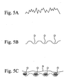
- Figs. 5A and 5B The function of dimples is explained by referring to Figs. 5A and 5B.
- the machined surface of the piston main body has V-grooves extending in the circumferential direction, microscopically, as shown in Fig. 5A.
- Fig. 5B shows dimples.
- dimples D serve as an oil reservoir to hold oil droplets O, as shown in Fig. 5C, and if a surface pressure is applied, an oil film S is held, and an increase in sliding resistance is prevented.
- Figs. 4A and 4B show the sectional shape of the convex portion shown in Figs. 3A and 3B, and specifically, Fig. 4A shows a state before initial wear, and Fig. 4B shows a state after running-in. As shown in Fig.
- fine corrugations are formed by shot peening in the convex portion, and a layer containing a solid lubricant of molybdenum disulfide is also formed.
- the oil holding improving effect on the surface by dimples and the solid lubrication effect by the molybdenum disulfide the initial wear of the initial fitting is terminated in a short time. That is, the balance of various factors such as the amount of lubricating oil supplied on the sliding surface and magnitude of the surface pressure generated on the sliding surface is achieved in an extremely short time by the layer containing molybdenum disulfide formed on the surface, and the sliding resistance is decreased substantially in the initial fitting. As shown in Fig.
- Such fitting phenomenon should preferably be completed earlier and at a smaller wear amount.
- the tip of the convex portion provided along the circumferential direction of the skirt portion on the sliding surface with the sleeve slides and is worn until the surface pressure is stabilized. This is because an extra tip portion of the convex portion is removed in order to maintain a corresponding surface area for withstanding the surface pressure of sliding.
- the removed tip portions are collected in the lubricating oil as worn particles.
- the convex portion is preferred to be trapezoidal in sectional view along the sliding direction. In this configuration, as compared with the case of forming sharp edges by machining, the surface pressure applied on the sliding surface, the surface roughness, and the amount of lubricating oil supplied depending on the relative sliding speed are stabilized earlier.
- Dimples must have a proper size for obtaining these effects. If the dimples are too small, the ability to hold the lubricating oil is insufficient, and the size of the bay is too small, and the action of pulling out the lubricating oil to the sliding surface is insufficient. On the other hand, if the dimples are too large, deformation of the convex shape is significant, and the effect of forming the convex portion is sacrificed, and the surface roughness is excessive, which may lead to an increase in the sliding resistance. Dimples can be formed by shot peening. In this case, since the size of the dimples is limited as explained above, the average depth of dimples is preferred to be 0.5 to 6.0 ⁇ m. The average depth of dimples is calculated by measuring the values of surface roughness Ra.
- Figs. 6A and 6B show the sectional shape of the convex portion before initial wear.
- Fig. 6A shows an arc-shaped section of the concave portion, but is not limited to this shape, and contrary to Fig. 6A, the convex portion may have an arc-shaped section (Fig. 6B), or concave portions and convex portions may be continuous to form corrugations in a sectional view (Fig. 6C).
- the section of the concave portion and convex portion may be trapezoidal (Fig. 6D) or triangular (Fig. 6E).
- the interval P of the convex portions is preferred to be 200 to 400 ⁇ m, and more preferably 250 to 300 ⁇ m.
- the height H 1 from the bottom of the concave portion to the tip of the convex portion before initial wear is preferred to be 7 to 15 ⁇ m, or more preferably 8 to 12 ⁇ m.
- the average size of fine powder of molybdenum disulfide colliding against the surface of the metallic sliding member is preferred to be 2 to 200 ⁇ m, and more preferably 4 to 10 ⁇ m.
- Dimples may be provided only on the convex portion surface, but are preferred to be provided on all surfaces including concave portions.
- the metallic sliding member of the invention is not limited to such a piston as described above, but may be applied to any other members sliding with respect to each other.
- it may be applied to reciprocating sliding parts or rotating sliding parts, such as a piston pin, sliding bearing for internal-combustion engine, cam shaft holder, etc.
- the invention may be applied also to parts abutting against or contacting with opposite parts, but not sliding with each other.
- the invention can also be applied to piston side surface, cam journal, cam end surface, crank journal surface, rocker arm slipper surface, oil pump rotor, oil pump rotor's case, or the like.
- Fig. 11 is a side sectional view showing a preferred embodiment of a surface treatment apparatus of the invention.
- reference numeral 11 is a powder tank
- reference numeral 12 is a powder amount adjusting tank.
- a feed pipe 16 is fixed, which extends downward to penetrate through the top wall of the powder amount adjusting tank 12.
- a feed port 19 of the feed pipe 16 is provided at a position of about 2/3 of the height from the bottom of the powder amount adjusting tank 12.
- a capturing rotary plate 21 is rotatably supported by a shaft 25 installed in a horizontal direction.
- plural V-section grooves (not shown) are formed on the entire circumference.
- a suction pipe 23 is positioned in the center of the peak of the capturing rotary plate 21.
- a suction port 24 is provided with its lower edge kept in contact with the outer circumference of the capturing rotary plate 21.
- the upper end of the suction pipe 23 protrudes by penetrating through the top wall of the powder amount adjusting tank 12, and an injection nozzle 13 is linked to its end through a powder feed pipe 14. Compressed air is supplied to the rear end of the injection nozzle 13.
- Reference numeral 70 in the diagram shows a recovery tank such as cyclone, and reference numeral 28 is a vibrator for keeping constant the amount of powder captured in the grooves on the outer circumference of the capturing rotary plate 21.
- the capturing rotary plate 21 rotates in the direction of the arrow, and the powder is captured in the grooves on the outer circumference.
- the compressed air is supplied into the injection nozzle 13
- the inside of the suction portion 24 is evacuated to have a negative pressure. Accordingly, when the powder reaches the suction port 24, it is sucked into the suction pipe 23 by the negative pressure, and is injected from the injection nozzle 13 through the powder feed pipe 14.
- the pressure of the compressed air is 0.5 MPa (gauge pressure)
- the powder of molybdenum disulfide injected from the injection nozzle 13 collides against the metallic sliding member, such as a piston, together with the compressed air, at a speed of 100 m/sec or more.
- a layer containing molybdenum disulfide as solid lubricant is formed within a depth of 20 ⁇ m from the surface of the metallic sliding member.
- the molybdenum disulfide powder is a mixture of ground powder and non-ground powder, but since no foreign matter is mixed therein in the invention, this powder is recoverable, and non-ground powder or ground powder having a specified particle size may be classified by a special classifier, and be supplied into the powder tank 11 from the powder feed portion 70 for recycling as indicated by double dot chain line in Fig. 11.
- the ground molybdenum dioxide powder having a small particle size is classified by the classifier, and may be used for other purposes. Therefore, according to the invention, the consumption of molybdenum disulfide powder can be substantially reduced, and hence the product cost can be lowered.
- FIG. 6D A piston of typical shape and size was fabricated. On the outer circumference of the piston, trapezoidal convex portions (stripes) as shown in Fig. 6D were formed, at the interval of convex portions of about 250 ⁇ m and height of convex portions of about 10 ⁇ m.
- Scaly fine powder of molybdenum disulfide of average size of 4 ⁇ m and purity of 98.6% by weight was blasted at the side surface of the piston at a distance of 50 mm by compressed air at a pressure of 8 atmospheres. The blasting duration to the piston was 8 minutes.
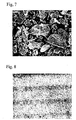
- Fig. 7 is an electron microscope photograph (500 times) of the molybdenum disulfide used herein.
- Fig. 10 shows time-course changes of the reduction index of friction loss output, assuming the reduction index of friction loss output upon start of running-in to be 1.
- the reduction index of friction loss output of 0.86 means that the sliding resistance is decreased by 14%.
- the reduction index of friction loss output upon start of running-in was about 0.87, and was stable at about 0.85 in 60 hours.
- the comparative example treated by shot peening using glass beads it took 80 hours until the reduction index of friction loss output was stabilized, and the value was about 0.87.
- the comparative example of the piston material without any treatment it took 100 hours until the reduction index of friction loss output was stabilized, and the value was about 0.9.
- the running-in ended in a shorter time, and the reduction index of friction loss output was substantially improved.
- molybdenum disulfide remained in 40 to 50 % by area.
- Fig. 8 shows an electron microscope photograph (100 times) of the side surface of the piston of the invention having molybdenum dioxide after running-in.
- molybdenum disulfide is driven in the entire side surface of the piston, and fine dimples remain.
- the surface roughness Ra of the piston side surface was measured, and the average Ra value was obtained as the average depth.
- the average depth of dimples was 1.8 ⁇ m.
- the driving depth of molybdenum disulfide (the dimension from the surface to the deepest end of molybdenum disulfide) was estimated to be about 6 ⁇ m.
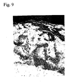
- Fig. 9 is an electron microscope photograph (2000 times) of the side section of the same piston. As shown in Fig.
- the driven molybdenum disulfide (dark area) is present near the piston surface. Gray and black spots beneath the molybdenum disulfide are recrystallized aluminum alloy portions.
- traces of intermetallic compounds such as ⁇ '-Mo 2 C and Al 8 Mo 3 were found in the boundary of the molybdenum disulfide and aluminum alloy portions. These intermetallic compounds are expected to increase the binding force between the molybdenum disulfide and aluminum alloy portions.
Landscapes
- Chemical & Material Sciences (AREA)
- Chemical Kinetics & Catalysis (AREA)
- Engineering & Computer Science (AREA)
- Materials Engineering (AREA)
- Mechanical Engineering (AREA)
- Metallurgy (AREA)
- Organic Chemistry (AREA)
- Pistons, Piston Rings, And Cylinders (AREA)
- Other Surface Treatments For Metallic Materials (AREA)
Abstract
Description
Claims (8)
- A metallic sliding member comprising a layer containing molybdenum disulfide as a solid lubricant within a depth of 20 µm from the surface thereof by collision of fine powder of molybdenum disulfide against the surface thereof.
- A metallic sliding member according to claim 1, wherein fine dimples are provided in the surface of the layer containing molybdenum disulfide.
- A piston for an internal combustion engine of which sliding parts are made of a metallic sliding member according to claim 1 or 2.
- A surface treatment method for a metallic sliding member comprising of a step for forming a layer containing molybdenum disulfide as a solid lubricant within a depth of 20 µm from the surface thereof by collision of a fine powder of molybdenum disulfide against the surface thereof together with compressed air of 0.5 MPa or more at a speed of 100 m/sec or more.
- A surface treatment method according to claim 4, wherein fine dimples are provided in the surface of the layer containing molybdenum disulfide.
- A surface treatment method for a piston for an internal combustion engine of which sliding parts are treated by a surface treatment method for a metallic sliding member according to claim 4 or 5.
- A surface treatment apparatus for forming a layer containing molybdenum disulfide as a solid lubricant within a depth of 20 µm from the surface thereof by collision of fine powder of molybdenum disulfide against the surface thereof together with compressed air of 0.5 MPa or more at a speed of 100 m/sec or more.
- A surface treatment apparatus according to claim 7, wherein fine dimples are provided in the surface of the layer containing molybdenum disulfide.
Applications Claiming Priority (3)
| Application Number | Priority Date | Filing Date | Title |
|---|---|---|---|
| JP2000350123 | 2000-11-16 | ||
| JP2000350123 | 2000-11-16 | ||
| PCT/JP2001/010053 WO2002040743A1 (en) | 2000-11-16 | 2001-11-16 | Metallic sliding member, piston for internal combustion engine, method of surface-treating these, and apparatus therefor |
Publications (3)
| Publication Number | Publication Date |
|---|---|
| EP1338679A1 true EP1338679A1 (en) | 2003-08-27 |
| EP1338679A4 EP1338679A4 (en) | 2006-11-08 |
| EP1338679B1 EP1338679B1 (en) | 2010-09-22 |
Family
ID=18823410
Family Applications (1)
| Application Number | Title | Priority Date | Filing Date |
|---|---|---|---|
| EP01983814A Expired - Lifetime EP1338679B1 (en) | 2000-11-16 | 2001-11-16 | Metallic sliding member and method of surface-treating thereof |
Country Status (7)
| Country | Link |
|---|---|
| US (2) | US6863922B2 (en) |
| EP (1) | EP1338679B1 (en) |
| JP (1) | JP4011478B2 (en) |
| CA (1) | CA2396577C (en) |
| DE (1) | DE60143123D1 (en) |
| MX (1) | MXPA02006983A (en) |
| WO (1) | WO2002040743A1 (en) |
Cited By (1)
| Publication number | Priority date | Publication date | Assignee | Title |
|---|---|---|---|---|
| DE102005006397B4 (en) * | 2004-02-18 | 2007-03-22 | Daido Metal Co. Ltd., Nagoya | Plain bearing for internal combustion engines |
Families Citing this family (32)
| Publication number | Priority date | Publication date | Assignee | Title |
|---|---|---|---|---|
| JP2004002912A (en) * | 2002-05-31 | 2004-01-08 | Nippon Piston Ring Co Ltd | Ferrous sintering cam lobe material |
| JP2004060742A (en) * | 2002-07-29 | 2004-02-26 | Nidec Tosok Corp | Ball screw |
| AU2003289340A1 (en) * | 2002-12-16 | 2004-07-09 | Matsushita Refrigeration Company | Refrigerant compressor, and refrigerating machine using the same |
| JP2004316699A (en) * | 2003-04-11 | 2004-11-11 | Nsk Ltd | Linear motion guide bearing device |
| US8414718B2 (en) * | 2004-01-14 | 2013-04-09 | Lockheed Martin Corporation | Energetic material composition |
| JP4776885B2 (en) * | 2004-03-11 | 2011-09-21 | 株式会社不二製作所 | Method for forming a film with flakes |
| JP2005307903A (en) * | 2004-04-23 | 2005-11-04 | Matsushita Electric Ind Co Ltd | Scroll compressor |
| US20070134468A1 (en) * | 2004-07-14 | 2007-06-14 | Buehler Jane E | Enhanced friction reducing surface and method of making the same |
| JP4603304B2 (en) * | 2004-07-20 | 2010-12-22 | Ntn株式会社 | Sealed rolling bearing |
| JP4665905B2 (en) * | 2005-01-18 | 2011-04-06 | 日本精工株式会社 | Method for manufacturing rolling device |
| CA2597266A1 (en) * | 2005-02-16 | 2006-08-24 | Mitsubishi Heavy Industries, Ltd. | Surface treatment method of titanium alloy member for aerospace equipment |
| JP3993204B2 (en) * | 2005-06-07 | 2007-10-17 | 株式会社不二機販 | Surface treatment method for sliding parts |
| JP4358801B2 (en) * | 2005-08-08 | 2009-11-04 | 大同メタル工業株式会社 | Slide bearing for internal combustion engine |
| US7886668B2 (en) * | 2006-06-06 | 2011-02-15 | Lockheed Martin Corporation | Metal matrix composite energetic structures |
| US8250985B2 (en) * | 2006-06-06 | 2012-08-28 | Lockheed Martin Corporation | Structural metallic binders for reactive fragmentation weapons |
| JP4658094B2 (en) | 2006-07-28 | 2011-03-23 | アート金属工業株式会社 | Piston surface modification method for internal combustion engine and piston for internal combustion engine |
| WO2008047931A1 (en) * | 2006-10-16 | 2008-04-24 | Panasonic Corporation | Sliding face modification material, method for producing sliding face modification material, method for using sliding face modification material, sliding members having sliding face modification material, and compressor comprising sliding members |
| US7536945B2 (en) * | 2006-12-29 | 2009-05-26 | Mahle Technology, Inc. | Piston pin for a combustion engine and method for its manufacture |
| JP5054452B2 (en) * | 2007-07-24 | 2012-10-24 | パナソニック株式会社 | Sliding member and manufacturing method thereof |
| JP2009120917A (en) * | 2007-11-16 | 2009-06-04 | Panasonic Corp | Sliding member and fluid machine |
| WO2009128258A1 (en) | 2008-04-14 | 2009-10-22 | 有限会社アプライドダイヤモンド | Oil-in-water type emulsion composition |
| JP4719249B2 (en) * | 2008-06-11 | 2011-07-06 | 株式会社不二機販 | Surface oxidation wear-resistant lubricating coating and method for forming the same |
| FR2933700B1 (en) * | 2008-07-08 | 2010-07-30 | Sanofi Aventis | PYRIDINO-PYRIDINONE DERIVATIVES, THEIR PREPARATION AND THEIR THERAPEUTIC APPLICATION |
| JP5117986B2 (en) * | 2008-10-08 | 2013-01-16 | アート金属工業株式会社 | Surface treatment method for piston skirt for internal combustion engine and piston for internal combustion engine |
| US8408116B2 (en) * | 2009-04-01 | 2013-04-02 | Delaware Capital Formation, Inc. | Method of fitting a piston for use in an internal combustion engine |
| US8389129B2 (en) | 2010-07-09 | 2013-03-05 | Climax Engineered Materials, Llc | Low-friction surface coatings and methods for producing same |
| US8038760B1 (en) | 2010-07-09 | 2011-10-18 | Climax Engineered Materials, Llc | Molybdenum/molybdenum disulfide metal articles and methods for producing same |
| DE102010051319A1 (en) * | 2010-11-13 | 2012-05-16 | Mahle International Gmbh | Piston for an internal combustion engine |
| US8507090B2 (en) | 2011-04-27 | 2013-08-13 | Climax Engineered Materials, Llc | Spherical molybdenum disulfide powders, molybdenum disulfide coatings, and methods for producing same |
| JP6653841B2 (en) * | 2015-03-31 | 2020-02-26 | 株式会社クボタ | Manufacturing method of sliding member |
| JP2018123916A (en) * | 2017-02-02 | 2018-08-09 | 日野自動車株式会社 | Sliding member |
| TWI880122B (en) * | 2021-10-14 | 2025-04-11 | 美商聖高拜塑膠製品公司 | Sliding material, bearing, and methods of making and using the same |
Family Cites Families (11)
| Publication number | Priority date | Publication date | Assignee | Title |
|---|---|---|---|---|
| US3574658A (en) * | 1967-12-22 | 1971-04-13 | Ball Brothers Res Corp | Dry-lubricated surface and method of producing such surfaces |
| JPS5216451U (en) | 1975-07-24 | 1977-02-05 | ||
| US4553417A (en) * | 1981-04-16 | 1985-11-19 | Miracle Metals, Inc. | Implantation of certain solid lubricants into certain metallic surfaces by mechanical inclusion |
| JPS57193941U (en) | 1981-06-04 | 1982-12-08 | ||
| US4753094A (en) * | 1986-06-19 | 1988-06-28 | Spears Richard L | Apparatus and method of powder-metal peen coating metallic surfaces |
| JP2818226B2 (en) * | 1989-11-22 | 1998-10-30 | 株式会社川邑研究所 | Method of forming solid lubricating film |
| US5486299A (en) * | 1993-11-02 | 1996-01-23 | Dow Corning Asia, Ltd | Wear-resistant lubricant composition |
| JP3212433B2 (en) * | 1993-12-28 | 2001-09-25 | 株式会社不二機販 | Wear prevention method for sliding parts of metal products |
| JPH07268620A (en) | 1994-03-28 | 1995-10-17 | Nikon Corp | Molybdenum sulfide lubricant film used at low load |
| JP3357586B2 (en) * | 1997-10-31 | 2002-12-16 | 株式会社不二機販 | Abrasion-resistant film molding of sliding part and film molding method |
| JP3822345B2 (en) | 1997-12-26 | 2006-09-20 | Ntn株式会社 | Solid lubricating film structure and solid lubricated rolling bearing |
-
2001
- 2001-11-16 US US10/169,063 patent/US6863922B2/en not_active Expired - Lifetime
- 2001-11-16 EP EP01983814A patent/EP1338679B1/en not_active Expired - Lifetime
- 2001-11-16 DE DE60143123T patent/DE60143123D1/en not_active Expired - Lifetime
- 2001-11-16 CA CA002396577A patent/CA2396577C/en not_active Expired - Fee Related
- 2001-11-16 WO PCT/JP2001/010053 patent/WO2002040743A1/en not_active Ceased
- 2001-11-16 MX MXPA02006983A patent/MXPA02006983A/en active IP Right Grant
- 2001-11-16 JP JP2002543050A patent/JP4011478B2/en not_active Expired - Lifetime
-
2004
- 2004-12-30 US US11/024,457 patent/US7399733B2/en not_active Expired - Lifetime
Cited By (2)
| Publication number | Priority date | Publication date | Assignee | Title |
|---|---|---|---|---|
| DE102005006397B4 (en) * | 2004-02-18 | 2007-03-22 | Daido Metal Co. Ltd., Nagoya | Plain bearing for internal combustion engines |
| US7771120B2 (en) | 2004-02-18 | 2010-08-10 | Daido Metal Corporation, Ltd. | Plain bearing for internal combustion engines |
Also Published As
| Publication number | Publication date |
|---|---|
| DE60143123D1 (en) | 2010-11-04 |
| WO2002040743A1 (en) | 2002-05-23 |
| EP1338679A4 (en) | 2006-11-08 |
| JP4011478B2 (en) | 2007-11-21 |
| CA2396577C (en) | 2006-12-19 |
| US20030000383A1 (en) | 2003-01-02 |
| JPWO2002040743A1 (en) | 2004-03-25 |
| CA2396577A1 (en) | 2002-05-23 |
| US6863922B2 (en) | 2005-03-08 |
| EP1338679B1 (en) | 2010-09-22 |
| MXPA02006983A (en) | 2002-12-13 |
| US20050202234A1 (en) | 2005-09-15 |
| US7399733B2 (en) | 2008-07-15 |
Similar Documents
| Publication | Publication Date | Title |
|---|---|---|
| US6863922B2 (en) | Metallic sliding member, piston for internal combustion engine, method of surface treating these, and apparatus therefor | |
| EP1111225B1 (en) | Sliding member and piston for internal combustion engine | |
| EP2549089B1 (en) | Piston for internal combustion engine | |
| RU2156370C1 (en) | Cylinder member such as cylinder liner, piston, piston skirt or piston ring in diesel engine, and piston ring for such engine | |
| EP1433838B1 (en) | Slide member | |
| JPWO2001002712A1 (en) | Slide member and piston for internal combustion engine | |
| JP2003184883A (en) | Bearing sliding member | |
| US8020529B2 (en) | Piston pin with slide layer for connecting rod eye for internal combustion engines | |
| KR102624586B1 (en) | Cylinder liners and cylinder bores | |
| JP2010031840A (en) | Cylinder block, internal combustion engine, transport equipment, and manufacturing method of cylinder block | |
| KR100411867B1 (en) | Reciprocating piston engine | |
| JP4122305B2 (en) | Slide bearing for internal combustion engine | |
| JP4358801B2 (en) | Slide bearing for internal combustion engine | |
| JP2002147459A (en) | Sliding bearing with overlay layer quality-improved | |
| US20220065188A1 (en) | Internal combustion engine including an element at the cylinder inner wall for scraping off oil carbon | |
| EP4219929B1 (en) | Internal combustion engine and transportation device | |
| JPH0641722A (en) | Sliding member and its production | |
| Haynes et al. | Accelerated chromium plate piston ring wear associated with liner pitting | |
| JPH09184079A (en) | Wear resistant member | |
| JPH08232754A (en) | Cylinder of internal combustion engine and manufacturing method thereof | |
| JPH0641721A (en) | Sliding member and its production | |
| JPH03247795A (en) | Cylinder for internal combustion engine |
Legal Events
| Date | Code | Title | Description |
|---|---|---|---|
| PUAI | Public reference made under article 153(3) epc to a published international application that has entered the european phase |
Free format text: ORIGINAL CODE: 0009012 |
|
| 17P | Request for examination filed |
Effective date: 20020702 |
|
| AK | Designated contracting states |
Designated state(s): BE DE ES FR GB |
|
| A4 | Supplementary search report drawn up and despatched |
Effective date: 20061011 |
|
| 17Q | First examination report despatched |
Effective date: 20071218 |
|
| GRAP | Despatch of communication of intention to grant a patent |
Free format text: ORIGINAL CODE: EPIDOSNIGR1 |
|
| RTI1 | Title (correction) |
Free format text: METALLIC SLIDING MEMBER AND METHOD OF SURFACE-TREATING THEREOF |
|
| GRAS | Grant fee paid |
Free format text: ORIGINAL CODE: EPIDOSNIGR3 |
|
| GRAA | (expected) grant |
Free format text: ORIGINAL CODE: 0009210 |
|
| RAP1 | Party data changed (applicant data changed or rights of an application transferred) |
Owner name: HONDA GIKEN KOGYO KABUSHIKI KAISHA |
|
| RIN1 | Information on inventor provided before grant (corrected) |
Inventor name: ISHIWATA, MASATOC/O KABUSHIKI KAISHA FUJI SEISAKUS Inventor name: OGIHARA, HIDEMIC/O KABUSHIKI KAISHA HONDA GIJUTSU |
|
| AK | Designated contracting states |
Kind code of ref document: B1 Designated state(s): BE DE ES FR GB |
|
| REG | Reference to a national code |
Ref country code: GB Ref legal event code: FG4D |
|
| REF | Corresponds to: |
Ref document number: 60143123 Country of ref document: DE Date of ref document: 20101104 Kind code of ref document: P |
|
| PG25 | Lapsed in a contracting state [announced via postgrant information from national office to epo] |
Ref country code: BE Free format text: LAPSE BECAUSE OF FAILURE TO SUBMIT A TRANSLATION OF THE DESCRIPTION OR TO PAY THE FEE WITHIN THE PRESCRIBED TIME-LIMIT Effective date: 20100922 |
|
| PG25 | Lapsed in a contracting state [announced via postgrant information from national office to epo] |
Ref country code: ES Free format text: LAPSE BECAUSE OF FAILURE TO SUBMIT A TRANSLATION OF THE DESCRIPTION OR TO PAY THE FEE WITHIN THE PRESCRIBED TIME-LIMIT Effective date: 20110102 |
|
| PLBE | No opposition filed within time limit |
Free format text: ORIGINAL CODE: 0009261 |
|
| STAA | Information on the status of an ep patent application or granted ep patent |
Free format text: STATUS: NO OPPOSITION FILED WITHIN TIME LIMIT |
|
| 26N | No opposition filed |
Effective date: 20110623 |
|
| REG | Reference to a national code |
Ref country code: DE Ref legal event code: R097 Ref document number: 60143123 Country of ref document: DE Effective date: 20110623 |
|
| REG | Reference to a national code |
Ref country code: DE Ref legal event code: R084 Ref document number: 60143123 Country of ref document: DE |
|
| REG | Reference to a national code |
Ref country code: GB Ref legal event code: 746 Effective date: 20140813 |
|
| REG | Reference to a national code |
Ref country code: DE Ref legal event code: R084 Ref document number: 60143123 Country of ref document: DE Effective date: 20140821 |
|
| REG | Reference to a national code |
Ref country code: FR Ref legal event code: PLFP Year of fee payment: 15 |
|
| PGFP | Annual fee paid to national office [announced via postgrant information from national office to epo] |
Ref country code: GB Payment date: 20151111 Year of fee payment: 15 |
|
| PGFP | Annual fee paid to national office [announced via postgrant information from national office to epo] |
Ref country code: FR Payment date: 20151008 Year of fee payment: 15 |
|
| GBPC | Gb: european patent ceased through non-payment of renewal fee |
Effective date: 20161116 |
|
| REG | Reference to a national code |
Ref country code: FR Ref legal event code: ST Effective date: 20170731 |
|
| PG25 | Lapsed in a contracting state [announced via postgrant information from national office to epo] |
Ref country code: FR Free format text: LAPSE BECAUSE OF NON-PAYMENT OF DUE FEES Effective date: 20161130 |
|
| PG25 | Lapsed in a contracting state [announced via postgrant information from national office to epo] |
Ref country code: GB Free format text: LAPSE BECAUSE OF NON-PAYMENT OF DUE FEES Effective date: 20161116 |
|
| PGFP | Annual fee paid to national office [announced via postgrant information from national office to epo] |
Ref country code: DE Payment date: 20171108 Year of fee payment: 17 |
|
| REG | Reference to a national code |
Ref country code: DE Ref legal event code: R119 Ref document number: 60143123 Country of ref document: DE |
|
| PG25 | Lapsed in a contracting state [announced via postgrant information from national office to epo] |
Ref country code: DE Free format text: LAPSE BECAUSE OF NON-PAYMENT OF DUE FEES Effective date: 20190601 |