EP1338460A2 - Driving assist system for vehicle - Google Patents
Driving assist system for vehicle Download PDFInfo
- Publication number
- EP1338460A2 EP1338460A2 EP03003684A EP03003684A EP1338460A2 EP 1338460 A2 EP1338460 A2 EP 1338460A2 EP 03003684 A EP03003684 A EP 03003684A EP 03003684 A EP03003684 A EP 03003684A EP 1338460 A2 EP1338460 A2 EP 1338460A2
- Authority
- EP
- European Patent Office
- Prior art keywords
- vehicle
- reactive force
- condition
- assist system
- subject vehicle
- Prior art date
- Legal status (The legal status is an assumption and is not a legal conclusion. Google has not performed a legal analysis and makes no representation as to the accuracy of the status listed.)
- Granted
Links
Images


Classifications
-
- B—PERFORMING OPERATIONS; TRANSPORTING
- B60—VEHICLES IN GENERAL
- B60K—ARRANGEMENT OR MOUNTING OF PROPULSION UNITS OR OF TRANSMISSIONS IN VEHICLES; ARRANGEMENT OR MOUNTING OF PLURAL DIVERSE PRIME-MOVERS IN VEHICLES; AUXILIARY DRIVES FOR VEHICLES; INSTRUMENTATION OR DASHBOARDS FOR VEHICLES; ARRANGEMENTS IN CONNECTION WITH COOLING, AIR INTAKE, GAS EXHAUST OR FUEL SUPPLY OF PROPULSION UNITS IN VEHICLES
- B60K31/00—Vehicle fittings, acting on a single sub-unit only, for automatically controlling vehicle speed, i.e. preventing speed from exceeding an arbitrarily established velocity or maintaining speed at a particular velocity, as selected by the vehicle operator
- B60K31/0008—Vehicle fittings, acting on a single sub-unit only, for automatically controlling vehicle speed, i.e. preventing speed from exceeding an arbitrarily established velocity or maintaining speed at a particular velocity, as selected by the vehicle operator including means for detecting potential obstacles in vehicle path
-
- B—PERFORMING OPERATIONS; TRANSPORTING
- B60—VEHICLES IN GENERAL
- B60K—ARRANGEMENT OR MOUNTING OF PROPULSION UNITS OR OF TRANSMISSIONS IN VEHICLES; ARRANGEMENT OR MOUNTING OF PLURAL DIVERSE PRIME-MOVERS IN VEHICLES; AUXILIARY DRIVES FOR VEHICLES; INSTRUMENTATION OR DASHBOARDS FOR VEHICLES; ARRANGEMENTS IN CONNECTION WITH COOLING, AIR INTAKE, GAS EXHAUST OR FUEL SUPPLY OF PROPULSION UNITS IN VEHICLES
- B60K26/00—Arrangement or mounting of propulsion-unit control devices in vehicles
- B60K26/02—Arrangement or mounting of propulsion-unit control devices in vehicles of initiating means or elements
- B60K26/021—Arrangement or mounting of propulsion-unit control devices in vehicles of initiating means or elements with means for providing feel, e.g. by changing pedal force characteristics
-
- B—PERFORMING OPERATIONS; TRANSPORTING
- B60—VEHICLES IN GENERAL
- B60W—CONJOINT CONTROL OF VEHICLE SUB-UNITS OF DIFFERENT TYPE OR DIFFERENT FUNCTION; CONTROL SYSTEMS SPECIALLY ADAPTED FOR HYBRID VEHICLES; ROAD VEHICLE DRIVE CONTROL SYSTEMS FOR PURPOSES NOT RELATED TO THE CONTROL OF A PARTICULAR SUB-UNIT
- B60W30/00—Purposes of road vehicle drive control systems not related to the control of a particular sub-unit, e.g. of systems using conjoint control of vehicle sub-units
- B60W30/14—Adaptive cruise control
- B60W30/16—Control of distance between vehicles, e.g. keeping a distance to preceding vehicle
-
- B—PERFORMING OPERATIONS; TRANSPORTING
- B60—VEHICLES IN GENERAL
- B60W—CONJOINT CONTROL OF VEHICLE SUB-UNITS OF DIFFERENT TYPE OR DIFFERENT FUNCTION; CONTROL SYSTEMS SPECIALLY ADAPTED FOR HYBRID VEHICLES; ROAD VEHICLE DRIVE CONTROL SYSTEMS FOR PURPOSES NOT RELATED TO THE CONTROL OF A PARTICULAR SUB-UNIT
- B60W50/00—Details of control systems for road vehicle drive control not related to the control of a particular sub-unit, e.g. process diagnostic or vehicle driver interfaces
- B60W50/08—Interaction between the driver and the control system
- B60W50/14—Means for informing the driver, warning the driver or prompting a driver intervention
- B60W2050/143—Alarm means
Definitions
- the present invention relates to a vehicle driving assist system that assists an operator to operate a vehicle and a vehicle equipped with the system.
- Systems employed to assist an operator to operate a vehicle include that disclosed in Japanese Laid Open Patent Publication No. 2000-54860.
- This system adjusts the reactive force against an accelerator pedal operation based upon the distance between a preceding vehicle and the subject vehicle detected with a laser radar or the like while automatic cruise control is implemented in the subject vehicle.
- the accelerator pedal reactive force is set to heavy as a warning to the operator if the detected distance between the vehicles becomes smaller than a predetermined value, and the accelerator pedal reactive force is also set to a greater value during the automatic cruise control so as to allow the operator to rest his foot on the accelerator pedal.
- the system described above does not enable the operator to verify whether or not any preceding vehicle has been detected without checking the monitor display or the like.
- another vehicle cuts in between the subject vehicle and the preceding vehicle and thus the condition surrounding the subject vehicle changes in a discontinuous manner while the automatic cruise control is engaged, it is difficult for the operator to promptly determine which of the two vehicles, i.e., the cut-in vehicle (the vehicle that has just cut in front of the subject vehicle) or the initial preceding vehicle, is currently being detected by the automatic cruise control system and which vehicle is being targeted by the system.
- a vehicle driving assist system comprises a condition recognition means for detecting a vehicle condition and a traveling environment around a subject vehicle; a reactive force application means for applying a reactive force, in conformance to the vehicle condition and the travelling environment around the subject vehicle detected by the condition recognition means, to an operation means for issuing a travel command for the subject vehicle; a condition change detection means for detecting a condition change occurring around the subject vehicle based upon the vehicle condition and the traveling environment around the subject vehicle detected by the condition recognition means; and a reactive force variation means for adjusting the reactive force applied by the reactive force application means in a period of time, when the condition change detection means detects that a condition around the subject vehicle has changed discontinuously.
- a vehicle according to the present invention comprises a vehicle driving assist system according to any one of claims 1 through 10.
- FIG. 1 is a system diagram of the structure adopted in a vehicle driving assist system 100 achieved in the embodiment and FIG. 2 shows the structure of the essential portion of an accelerator pedal 1 employed in the driving assist system 100.
- FIG. 9 shows how the vehicle driving assist system 100 is installed in a vehicle. It is to be noted that the following explanation focuses on an example in which the vehicle driving assist system 100 is adopted in a so-called automatic vehicle tracking system in which the distance between vehicles is automatically controlled in conformance to the extent to which the accelerator pedal 1 is operated.
- the accelerator pedal 1 is supported by a spring 3 via a wire 2 and a servomotor 4 that is linked to the rotating shaft of the accelerator pedal 1.
- reference numeral 5 indicates a body panel.
- a spring reactive force corresponding to the extent to which the pedal is operated is applied to the accelerator pedal 1 by the spring 3 and also a motor reactive force is applied to the accelerator pedal 1 by the servomotor 4.
- the motor reactive force is controlled based upon the results of a preceding vehicle detection and it is controlled to remain at 0 if no preceding vehicle is detected.
- the vehicle driving assist system 100 includes a laser radar 10 mounted at the front grille of the vehicle.
- the laser radar may be mounted to a front bumper of the vehicle.
- the laser radar is of a type which can scan horizontally and laterally about 6 degrees to each side of an axis parallel to the vehicle longitudinal centerline, by propagating infrared pulses forwardly and receiving the reflected radiation by an obstacle, such as a rear bumper of a preceding vehicle.
- the laser radar 10 provides a vehicle separation or a distance D between the subject vehicle and the preceding vehicle. It is to be noted that the vehicle distance D and the relative velocity ⁇ V are both 0 if no preceding vehicle is detected by the laser radar 10.
- a vehicle velocity sensor 14 detects the travelling speed of the subject vehicle based upon the rotation rate of the wheels or the like and outputs a detection signal to a controller 11.
- the controller 11 comprises a CPU and CPU peripheral components such as a ROM and a RAM, and a condition change detection device 12 and a reactive force calculating device 13 are achieved in the form of software in the CPU.
- the condition change detection device 12 detects a change occurring with regard to the condition surrounding the subject vehicle based upon the vehicle distance D and the relative velocity ⁇ V input from the laser radar 10.
- the condition change detection device 12 reads the signals input from the laser radar 10 every 100 ⁇ sec, for instance, and detects or determines that there is a condition change caused by another vehicle cutting in between the preceding vehicle and the subject vehicle if the difference between the current input values and the previous input values become equal to or greater than preset specific values (to be referred to as first predetermined values), i.e., if the vehicle distance D and the relative velocity ⁇ V change discontinuously.
- the condition change detection device 12 determines that there is a condition change resulting from starting a preceding vehicle detection if the vehicle distance D and the relative velocity ⁇ V indicate a change by an extent equal to or exceeding the first predetermined value Da and ⁇ Va.
- a preceding vehicle has already been detected, it determines a condition change resulting from stopping a preceding vehicle detection if the vehicle distance D and the relative velocity ⁇ V both become 0.
- the condition change detection device 12 determines that there is no condition change while the vehicle distance D and the relative velocity ⁇ V vary continuously. It is to be noted that the first predetermined values Da and ⁇ Va regarding the vehicle distance D and the relative vehicle velocity ⁇ V are set in advance in appropriate manner.
- the reactive force calculating device 13 calculates a target reactive force Fm + ⁇ Fm as explained in detail later based upon the input signals provided by the laser radar 10, the vehicle velocity sensor 14 and the condition change detection device 12 and outputs a signal corresponding to the target reactive force to a reactive force control device 15.
- the reactive force control device 15 outputs a control signal to the servomotor 4 so that the target reactive force Fm + ⁇ Fm is applied to the accelerator pedal 1.
- the torque corresponding to the target reactive force is generated at the servomotor 4 and when the operator operates the accelerator pedal 1 he feels the motor reactive force generated by the servomotor 4 in addition to the spring reaction force generated by the spring 3.
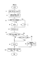
- FIG. 3 presents a flowchart of an example of the processing procedure of the program executed by the controller 11 in the first embodiment.
- the processing in this flowchart which may start in response to an ON operation of, for instance, a switch through which an automatic tracking operation start command is issued, is repeatedly executed over predetermined time intervals (e.g., every 100 ⁇ sec).
- step S1 the subject vehicle velocity V detected by the vehicle velocity sensor 14 is read in step S1 and then the vehicle distance D and the relative velocity ⁇ V detected by the laser radar 10 are read in step S2.
- step S3 a decision is made as to whether or not any condition change has occurred in the environment around the vehicle based upon the vehicle distance D and the relative velocity ⁇ V. If it is decided that there is a condition change due to another vehicle cutting in between the preceding vehicle and the subject vehicle, a preceding vehicle detection start or a preceding vehicle detection stop, as described above, the operation proceeds to step S4.
- step S6 calculate a target reactive force Fm in response to the vehicle condition and the traveling environment around the subject vehicle by using, for instance, the formula presented in expression (1) below.
- Fm ⁇ ( ⁇ V/D + V/D) (when Fm > 0)
- ⁇ represents a constant and the relative velocity ⁇ V represents the absolute value (
- the value obtained by dividing the relative velocity ⁇ V by the vehicle distance, which is a reciprocal of a time to contact TTC, represents a degree of proximity or closeness to the preceding vehicle from the subject vehicle.
- the value obtained by dividing the subject vehicle velocity V by the vehicle distance D, which is a reciprocal of a time headway THW represents a time required for the subject vehicle to reach the point that the preceding vehicle currently exists.
- the target reactive force Fm increases as the distance D to the preceding vehicle becomes smaller and thus as the degree of the proximity to the preceding vehicle increases. It is to be noted that the target reactive force Fm is at 0 if no preceding vehicle is detected.
- step S8 an additional pulse ⁇ Fm is generated over a predetermined length of time ⁇ t.
- the additional pulse ⁇ Fm is a reactive force to be added to the target reactive force Fm calculated in step S8 and is set in advance to a value corresponding to the vehicle velocity V and the vehicle distance D.
- a total target reactive force (Fm + ⁇ Fm) is calculated by adding the additional pulse ⁇ Fm to the target reactive force Fm and a signal corresponding to the new target reactive force (Fm + ⁇ Fm) is output to the reactive force control device 15.
- the reactive force control device 15 outputs a control signal corresponding to the target reactive force (Fm + ⁇ Fm) to the servomotor 4, thereby controlling the torque of the servomotor 4. Consequently, a motor reactive force equivalent to the target reactive force (Fm + ⁇ Fm) is applied to the accelerator pedal 1.
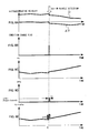
- FIGS. 4A ⁇ 4E respectively show the operational characteristics varying along a time axis prior to and following a preceding vehicle detection, with regard to the vehicle distance D and the relative velocity ⁇ V, the condition change flag, the target reactive force Fm, the additional pulse ⁇ Fm and the total target reactive force Fm + ⁇ Fm.
- the vehicle distance D, the relative velocity ⁇ V, the target reactive force Fm and the like are all set at 0. Accordingly, even when the vehicle is set in the automatic tracking mode, only the spring reactive force attributable to the spring 3 is applied to the accelerator pedal 1 in this state. Prior to the preceding vehicle detection, the vehicle does not engage in the automatic tracking operation and instead, the vehicle travels at the engine torque corresponding to the extent to which the accelerator pedal 1 is operated.
- the preceding vehicle detection starts (at a time point t1).
- the vehicle distance D rapidly or discontinuously increases from 0 and the relative velocity ⁇ V rapidly or discontinuously decreases from 0, as shown in FIG. 4A.
- the target reactive force Fm based upon the traveling environment is calculated (step S6), as shown in FIG. 4C.
- the motor reactive force (Fm + ⁇ Fm) shown in FIG. 4E is applied to the accelerator pedal 1, which rapidly increases the level of the motor reactive force at the preceding vehicle detection start. This rapid change in the motor reactive force (Fm + ⁇ Fm) allows the operator to sense via the accelerator pedal 1 that a preceding vehicle detection has started.
- FIGS. 5A ⁇ 5E respectively show the operational characteristics varying along the time axis prior to and following a cut-in vehicle detection, with regard to the vehicle distance D and the relative velocity ⁇ V, the condition change flag, the target reactive force Fm, the additional pulse ⁇ Fm and the total target reactive force Fm + ⁇ Fm.
- the subject vehicle is engaged in a traveling operation by tracking the preceding vehicle while maintaining the vehicle distance D corresponding to the extent to which the accelerator pedal 1 is operated and maintains the relative velocity at 0 prior to a cut-in vehicle detection.
- the target reactive force Fm corresponding to the vehicle distance D, the vehicle velocity V and the relative velocity ⁇ V is applied to the accelerator pedal 1, as shown in FIG. 5C.
- the additional pulse ⁇ Fm prior to the cut-in vehicle detection is 0.
- the laser radar 10 switches the detection target for detecting the vehicle distance D and the relative velocity ⁇ V to the cut-in vehicle and detects the distance to and the speed relative to the new preceding vehicle (at the time point t1), thereby switching the object of the control implemented by the tracking control system.
- the vehicle distance D and the relative velocity ⁇ V change rapidly (discontinuously) as shown in FIG. 5A.
- step S8 the total target reactive force (Fm + ⁇ Fm) which is obtained by adding the additional pulse ⁇ Fm to the target reaction force Fm is output to the reactive force control device 15 (step S10).
- the motor reactive force (Fm + ⁇ Fm) shown in FIG. 5E is applied to the accelerator pedal 1 so that the rapid increase in the motor reactive force at the time point t1 allows the operator to recognize that the detection of a cut-in vehicle has started.
- the vehicle driving assist system 100 in the first embodiment of the present invention achieves the following advantages.
- FIG. 6 presents a flowchart of an example of the processing procedure of the program executed by the controller 11 in the second embodiment. It is to be noted that in FIG. 6 the same step numbers are assigned to steps in which processing similar to that in FIG. 3 is executed and that the following explanation focuses on the difference from the processing shown in FIG. 3.
- step S21 the target reactive force Fm (k - 1) previously calculated through an arithmetic operation immediately before the occurrence of the condition change is subtracted from the target reactive force Fm(k) calculated through the current arithmetic operation in step S6 immediately following the occurrence of the condition change. Then, a decision is made as to whether or not the difference (Fm(k) - Fm(k - 1)) is equal to or greater than a preset specific value (to be referred to as a second specific value) ⁇ F.
- the second predetermined value ⁇ F may be set to equal to , for instance, the additional pulse ⁇ F0 used in the first embodiment.
- step S21 If an affirmative decision is made in step S21, the operation proceeds to step S9 to set 0 to the additional pulse ⁇ Fm. On the other hand, if a negative decision is made in step S21, the operation proceeds to step S8 to set ⁇ F0 to the additional pulse ⁇ Fm.
- the additional pulse ⁇ Fm is added only if the extent (Fm(k) - Fm(k - 1)) of the change in the target reactive force following the preceding vehicle detection relative to the target reactive force prior to the preceding vehicle detection is smaller than the second predetermined value ⁇ F in the second embodiment.
- the operator is able to recognize that a preceding vehicle has been detected.
- an application of an unnecessarily large motor reactive force to the accelerator pedal 1 is prevented to achieve better operability of the accelerator pedal 1 since no additional pulse ⁇ Fm is added when the extent of the change in the target reactive force Fm attributable to the detection of the preceding vehicle.
- FIG. 7 presents a flowchart of an example of the processing executed by the controller 11 in the third embodiment. It is to be noted that in FIG. 7 the same step numbers are assigned to steps in which processing identical to that in FIG. 3 is executed and that the following explanation focuses on the difference from the processing shown in FIG. 3.
- step S31 the target reactive force Fm (k - 1) previously calculated through an arithmetic operation immediately before the occurrence of the condition change is subtracted from the target reactive force Fm(k) calculated through the current arithmetic operation in step S6 immediately following the occurrence of the condition change. Then, a decision is made as to whether or not the absolute value of the difference
- the second predetermined value ⁇ F may be set to equal to it, for instance, the additional pulse ⁇ F0 used in the first embodiment. If an affirmative decision is made in step S31, the operation proceeds to step S9 to set 0 to the additional pulse ⁇ Fm. On the other hand, if a negative decision is made in step S31, the operation proceeds to step S32.
- step S32 a decision is made as to whether or not the difference (Fm(k) - Fm(k - 1)) obtained by subtracting the target reactive force Fm(k - 1) immediately before the occurrence of the condition change from the target reactive force Fm(k) immediately after the occurrence of the condition change is equal to or greater than 0, i.e., the target reactive force Fm(k) is equal to or greater than the target reactive force Fm(k - 1).
- step S33 If it is decided that the target reactive force Fm(k) is equal to or greater than the value Fm(k-1) (Fm(k) > Fm(k - 1)), the operation proceeds to step S33, whereas if it is decided that the target reaction force Fm(k) is smaller than the value Fm(k-1) (Fm(k) ⁇ Fm(k - 1)), the operation proceeds to step S8.
- step S33 the value ( ⁇ F0 - (Fm(k) - Fm(k-1))) obtained by subtracting the difference between the reactive forces Fm(k) and Fm(k-1) from the predetermined additional pulse ⁇ F0 is set for the additional pulse ⁇ Fm before the operation proceeds to step S10.
- FIGS. 8A ⁇ 8E respectively show the operational characteristics varying along the time axis prior to and following a cut-in vehicle detection, with regard to the vehicle distance D and the relative velocity ⁇ V, the condition change flag, the target reactive force Fm, the additional pulse ⁇ Fm and the total target reactive force Fm + ⁇ Fm.
- the additional force ⁇ Fm added to the motor reactive force which is applied to the accelerator pedal 1 becomes constant at ⁇ F0 regardless of the difference between the target reactive forces attributable to the detection of the cut-in vehicle, which makes it possible to minimize the increase in the reactive force to the minimal degree which is necessary to alert an operator.
- the additional pulse ⁇ F0 is output over the predetermined length of time ⁇ t (step S8).
- the motor reactive force changes rapidly to enable the operator to recognize that the detection of a cut-in vehicle has started.
- the additional pulse ⁇ Fm corresponding to the difference (F0 - (Fm (k) - Fm(k - 1))) is added. Accordingly, the motor reactive force is increased by a constant degree ⁇ F0 when the condition change has occurred. Thus, it is possible to alert the operator that a cut-in vehicle detection has started while minimizing the increase in the motor reactive force.
- the vehicle driving assist system is not limited to the examples presented in the embodiments described above and allows for a number of variations. While the sum (Fm + ⁇ Fm) of the target reactive force Fm and the additional pulse ⁇ Fm is output as the motor reactive force when the condition change has been detected in the embodiments described above, the difference (Fm - ⁇ Fm) obtained by subtracting the additional pulse ⁇ Fm from the target reactive force Fm may instead be output as the motor reactive force. In this case, too, the operator is easily able to recognize that a preceding vehicle detection has started through a rapid change in the motor reactive force.
- the target reactive force Fm is calculated by using a reciprocal ( ⁇ V/D) of the time to contact and a reciprocal (V/D) of the time headway, however, the present invention is not limited to this example.
- the target reactive force Fm may be calculated, for instance, by using only the reciprocal ( ⁇ V/D) of the time to contact.
- the waveform of the reactive force ⁇ Fm is not limited to this example.
- the reactive force ⁇ Fm may be gradually increased or gradually reduced.
- the additional reactive force ⁇ Fm may be repeatedly applied during the predetermined period of time ⁇ t. In other words, a reactive force ⁇ Fm with a high frequency waveform may be added.
- any additional force ⁇ F may be added, as long as the reactive force applied to the accelerator pedal 1 is adjusted in a period of time, when the condition change around the subject vehicle has been detected so that the operator is able to ascertain the condition change around the vehicle via the accelerator pedal 1.
- the present invention is not limited to this example, and the system may be adopted in a vehicle that does not implement vehicle distance control as long as accelerator pedal reactive force control is implemented based upon the traveling environment around the subject vehicle and the operator is easily able to recognize a condition change occurring around the vehicle as a change in the accelerator pedal reactive force.
- the vehicle distance control may be started or cleared in conformance to, for instance, the stroke quantity of the accelerator pedal 1.
- the laser radar 10 in the embodiments described above may be a radar adopting another detection method such as a milliwave radar.
- the operation device which is used to issue a travel command for the vehicle may be a member other than the accelerator pedal 1, such as a brake pedal. While a preceding vehicle is detected with the laser radar 10, an object other than a preceding vehicle may be detected.
- the servomotor 4 is employed to apply the reactive force, the reactive force may be applied with another actuator. While a single servomotor 4 is used to generate the target reactive force Fm and the additional reactive force ⁇ Fm, the target reactive force Fm and the additional reactive force ⁇ Fm may be generated by separate actuators, as well.
Landscapes
- Engineering & Computer Science (AREA)
- Transportation (AREA)
- Mechanical Engineering (AREA)
- Chemical & Material Sciences (AREA)
- Combustion & Propulsion (AREA)
- Automation & Control Theory (AREA)
- Control Of Driving Devices And Active Controlling Of Vehicle (AREA)
- Auxiliary Drives, Propulsion Controls, And Safety Devices (AREA)
- Controls For Constant Speed Travelling (AREA)
- Steering Control In Accordance With Driving Conditions (AREA)
Abstract
Description
Accordingly, the motor reactive force is increased by a constant degree ΔF0 when the condition change has occurred. Thus, it is possible to alert the operator that a cut-in vehicle detection has started while minimizing the increase in the motor reactive force.
Claims (11)
- A vehicle driving assist system comprising:a condition recognition means (10, 14) for detecting a vehicle condition and a traveling environment around a subject vehicle;a reactive force application means (13) for applying a reactive force, in conformance to the vehicle condition and the travelling environment around the subject vehicle detected by the condition recognition means, to an operation means (1) for issuing a travel command for the subject vehicle;a condition change detection means (12) for detecting a condition change occurring around the subject vehicle based upon the vehicle condition and the traveling environment around the subject vehicle detected by the condition recognition means (10, 14); anda reactive force variation means (13) for adjusting the reactive force applied by the reactive force application means (13) in a period of time, when the condition change detection means (12) detects that a condition around the subject vehicle has changed discontinuously.
- A vehicle driving assist system according to claim 1, wherein:the reactive force variation means (13) adjusts the reactive force applied by the reactive force application means (13) in pulse shape.
- A vehicle driving assist system according to claim 1 or claim 2, wherein:the reactive force variation means (13) adjusts the reactive force applied by the reactive force application means (13) so that the reactive force is allowed to change at a constant degree when the condition change detection means (12) detects that the condition around the subject vehicle has changed.
- A vehicle driving assist system according to any one of claims 1 through 3, wherein:the condition recognition means (10, 14) detects a relative velocity and a distance between the subject vehicle and a preceding vehicle as the vehicle condition and the traveling environment andthe condition change detection means (12) determines whether the condition around the subject vehicle has changed discontinuously based upon the relative velocity and the vehicle distance detected by the condition recognition means (10, 14).
- A vehicle driving assist system according to any one of claims 1, 2 and 4, wherein:the reactive force application means (13) calculates a target reactive force to be applied to the operation means based upon the vehicle condition and the traveling environment around the subject vehicle, andthe reactive force variation means (13) adds an additional force to the target reactive force if a change of the target reactive force due to the condition change is smaller than a predetermined value, when the condition change detection means (12) detects that the condition around the subject vehicle has changed discontinuously.
- A vehicle driving assist system according to any one of claims 1, 2 and 4, wherein:the reactive force application means (13) calculates a target reactive force to be applied to the operation means (1) based upon the vehicle condition and the traveling environment around the subject vehicle, andthe reactive force variation means (13) adds an additional force for regulating a change of the reactive force applied to the operation means (1) at a constant degree, to the target reactive force if a change of the target reactive force due to the condition change is smaller than a predetermined value and the target reactive force after the condition change is greater than the target reactive force before the condition change, when the condition change detection means (12) detects that the condition around the subject vehicle has changed discontinuously.
- A vehicle driving assist system according to claim 5 or claim 6, wherein:the reactive force variation means (13) sets substantially 0 to the additional force when the change of the target force due to the condition change is equal to or greater than the predetermined value.
- A vehicle driving assist system according to any one of claims 5 through 7, wherein:the condition recognition means (10, 14) detects a relative velocity and a distance between the subject vehicle and a preceding vehicle and a velocity of the subject vehicle as the vehicle condition and the traveling environment andthe reactive force application means (13) calculates the target reactive force based upon the relative velocity, the vehicle distance and the subject vehicle velocity detected by the condition recognition means (10, 14).
- A vehicle driving assist system according to any one of claims 5 through 8, wherein:the reactive force variation means (13) adds the additional force to the target reactive force over a predetermined time period.
- A vehicle driving assist system according to any one of claims 1 through 9, wherein:the operation means (1) is an accelerator pedal andthe reactive force application means (13) applies the reactive force to the accelerator pedal.
- A vehicle comprising:a vehicle driving assist system according to any one of claims 1 through 10.
Applications Claiming Priority (2)
| Application Number | Priority Date | Filing Date | Title |
|---|---|---|---|
| JP2002048190A JP3573134B2 (en) | 2002-02-25 | 2002-02-25 | Driving operation assist device for vehicles |
| JP2002048190 | 2002-02-25 |
Publications (3)
| Publication Number | Publication Date |
|---|---|
| EP1338460A2 true EP1338460A2 (en) | 2003-08-27 |
| EP1338460A3 EP1338460A3 (en) | 2006-02-01 |
| EP1338460B1 EP1338460B1 (en) | 2009-02-11 |
Family
ID=27655437
Family Applications (1)
| Application Number | Title | Priority Date | Filing Date |
|---|---|---|---|
| EP03003684A Expired - Lifetime EP1338460B1 (en) | 2002-02-25 | 2003-02-18 | Driving assist system for vehicle |
Country Status (4)
| Country | Link |
|---|---|
| US (1) | US7124010B2 (en) |
| EP (1) | EP1338460B1 (en) |
| JP (1) | JP3573134B2 (en) |
| DE (1) | DE60326095D1 (en) |
Cited By (4)
| Publication number | Priority date | Publication date | Assignee | Title |
|---|---|---|---|---|
| FR2882003A1 (en) * | 2005-02-15 | 2006-08-18 | Renault Sas | PILOT ACCELERATOR PEDAL ASSEMBLY |
| US7124010B2 (en) * | 2002-02-25 | 2006-10-17 | Nissan Motor Co., Ltd. | Driving assist system for vehicle |
| CN104139701A (en) * | 2013-05-07 | 2014-11-12 | 现代自动车株式会社 | Active control method of pedal effort for accelerator |
| CN105584367A (en) * | 2016-03-07 | 2016-05-18 | 成都亨通兆业精密机械有限公司 | Intelligent pedal control system |
Families Citing this family (26)
| Publication number | Priority date | Publication date | Assignee | Title |
|---|---|---|---|---|
| JP3531640B2 (en) * | 2002-01-10 | 2004-05-31 | 日産自動車株式会社 | Driving operation assist device for vehicles |
| JP3873876B2 (en) * | 2002-12-06 | 2007-01-31 | 日産自動車株式会社 | VEHICLE DRIVE OPERATION ASSISTANCE DEVICE AND VEHICLE HAVING THE DEVICE |
| JP3896993B2 (en) * | 2003-06-04 | 2007-03-22 | 日産自動車株式会社 | VEHICLE DRIVE OPERATION ASSISTANCE DEVICE AND VEHICLE HAVING VEHICLE DRIVE OPERATION ASSISTANCE DEVICE |
| JP3882797B2 (en) * | 2003-08-08 | 2007-02-21 | 日産自動車株式会社 | VEHICLE DRIVE OPERATION ASSISTANCE DEVICE AND VEHICLE HAVING VEHICLE DRIVE OPERATION ASSISTANCE DEVICE |
| JP4131327B2 (en) * | 2003-09-22 | 2008-08-13 | 日産自動車株式会社 | VEHICLE DRIVE OPERATION ASSISTANCE DEVICE AND VEHICLE WITH VEHICLE DRIVE OPERATION ASSISTANCE DEVICE |
| JP4487534B2 (en) * | 2003-10-23 | 2010-06-23 | 日産自動車株式会社 | VEHICLE DRIVE OPERATION ASSISTANCE DEVICE AND VEHICLE HAVING VEHICLE DRIVE OPERATION ASSISTANCE DEVICE |
| JP4419531B2 (en) * | 2003-11-20 | 2010-02-24 | 日産自動車株式会社 | VEHICLE DRIVE OPERATION ASSISTANCE DEVICE AND VEHICLE HAVING VEHICLE DRIVE OPERATION ASSISTANCE DEVICE |
| JP4254501B2 (en) | 2003-11-20 | 2009-04-15 | 日産自動車株式会社 | VEHICLE DRIVE OPERATION ASSISTANCE DEVICE AND VEHICLE HAVING VEHICLE DRIVE OPERATION ASSISTANCE DEVICE |
| JP3960317B2 (en) | 2004-03-03 | 2007-08-15 | 日産自動車株式会社 | VEHICLE DRIVE OPERATION ASSISTANCE DEVICE AND VEHICLE WITH VEHICLE DRIVE OPERATION ASSISTANCE DEVICE |
| JP4367322B2 (en) * | 2004-11-26 | 2009-11-18 | 日産自動車株式会社 | VEHICLE DRIVE OPERATION ASSISTANCE DEVICE AND VEHICLE HAVING VEHICLE DRIVE OPERATION ASSISTANCE DEVICE |
| JP4674464B2 (en) * | 2004-12-02 | 2011-04-20 | 日産自動車株式会社 | VEHICLE DRIVE OPERATION ASSISTANCE DEVICE AND VEHICLE WITH VEHICLE DRIVE OPERATION ASSISTANCE DEVICE |
| US7664584B2 (en) * | 2005-03-01 | 2010-02-16 | Nissan Motor Co., Ltd. | Steering control system |
| US7444241B2 (en) * | 2005-12-09 | 2008-10-28 | Gm Global Technology Operations, Inc. | Method for detecting or predicting vehicle cut-ins |
| US8000874B2 (en) * | 2006-03-10 | 2011-08-16 | Nissan Motor Co., Ltd. | Vehicle headway maintenance assist system and method |
| JP4816248B2 (en) | 2006-05-23 | 2011-11-16 | 日産自動車株式会社 | Driving assistance device for vehicle |
| JP4765766B2 (en) * | 2006-05-23 | 2011-09-07 | 日産自動車株式会社 | VEHICLE DRIVE OPERATION ASSISTANCE DEVICE AND VEHICLE WITH VEHICLE DRIVE OPERATION ASSISTANCE DEVICE |
| JP4835539B2 (en) * | 2007-08-10 | 2011-12-14 | トヨタ自動車株式会社 | Driving force control device |
| EP2052936B1 (en) | 2007-10-23 | 2012-02-29 | Nissan Motor Co., Ltd. | Headway distance maintenance assisting system and method |
| JP5689471B2 (en) * | 2010-09-21 | 2015-03-25 | 本田技研工業株式会社 | Vehicle travel control device |
| JP5806480B2 (en) * | 2011-02-23 | 2015-11-10 | 株式会社ミクニ | Accelerator pedal device |
| JP5969220B2 (en) * | 2012-02-28 | 2016-08-17 | 株式会社日本自動車部品総合研究所 | Inter-vehicle distance control device |
| US9809219B2 (en) * | 2014-01-29 | 2017-11-07 | Continental Automotive Systems, Inc. | System for accommodating a pedestrian during autonomous vehicle operation |
| DE102015004478A1 (en) * | 2015-04-07 | 2016-10-13 | Lucas Automotive Gmbh | A control system and method for enabling a shunting of another motor vehicle from a neighboring lane in the ACC operation of the own motor vehicle |
| JP6575451B2 (en) * | 2016-07-20 | 2019-09-18 | 株式会社デンソー | Driving support device and driving support program |
| DE102017004536A1 (en) * | 2017-05-11 | 2018-11-15 | Lucas Automotive Gmbh | System and method for predictive speed control of a motor vehicle |
| DE102017209666A1 (en) * | 2017-06-08 | 2018-12-13 | Robert Bosch Gmbh | Method and apparatus for providing a signal for operating at least two vehicles |
Family Cites Families (49)
| Publication number | Priority date | Publication date | Assignee | Title |
|---|---|---|---|---|
| JPS5733048A (en) | 1980-08-04 | 1982-02-23 | Honda Motor Co Ltd | Throttle reaction control device of car |
| DE3071395D1 (en) * | 1980-10-07 | 1986-03-13 | Kozlekedestudomanyi Intezet | Method and device for qualifying the shock absorbers of sprung vehicles equipped with resilient tyres, especially power-driven road vehicles |
| JPH0624953B2 (en) * | 1986-04-08 | 1994-04-06 | 本田技研工業株式会社 | Electric power steering device |
| JPH0662092B2 (en) * | 1986-04-11 | 1994-08-17 | 本田技研工業株式会社 | Electric power steering device |
| JPH0192537A (en) | 1987-10-01 | 1989-04-11 | Mitsubishi Electric Corp | Accelerator pedal device for vehicle |
| JPH0293134A (en) | 1988-09-29 | 1990-04-03 | Kinugawa Rubber Ind Co Ltd | Vibration isolating bush |
| JP2565384B2 (en) * | 1988-09-30 | 1996-12-18 | 富士重工業株式会社 | Control device for automobile active suspension |
| JP2658467B2 (en) | 1990-01-22 | 1997-09-30 | 日産自動車株式会社 | Accelerator reaction force control device |
| JP2883724B2 (en) * | 1990-11-13 | 1999-04-19 | 本田技研工業株式会社 | Brake equipment |
| US5473539A (en) * | 1992-12-11 | 1995-12-05 | Honda Giken Kogyo Kabushiki Kaisha | Electrically operated power steering apparatus |
| JP2906101B2 (en) | 1993-02-25 | 1999-06-14 | 日野自動車工業株式会社 | Accelerator pedal vibration device |
| JP2950096B2 (en) * | 1993-06-01 | 1999-09-20 | 三菱自動車工業株式会社 | Electronically controlled power steering device |
| DE4419049C2 (en) * | 1993-06-01 | 2002-10-31 | Mitsubishi Motors Corp | Control system and method for a power steering device |
| JP3523698B2 (en) * | 1994-12-21 | 2004-04-26 | 光洋精工株式会社 | Electric power steering device and preventive safety device |
| DE19505629B4 (en) * | 1995-02-18 | 2004-04-29 | Diehl Stiftung & Co.Kg | Protective device against an approaching projectile |
| JPH08318765A (en) * | 1995-05-25 | 1996-12-03 | Hitachi Ltd | Information vehicle control apparatus and method |
| US5805103A (en) | 1995-09-27 | 1998-09-08 | Mazda Motor Corporation | Method of and system for monitoring preceding vehicles |
| US6142581A (en) * | 1995-12-26 | 2000-11-07 | Denso Corporation | Hydraulic circuit having a rotary type pump and brake apparatus for a vehicle provided with the same |
| EP1155933B1 (en) * | 1995-12-26 | 2006-04-12 | Denso Corporation | Brake control apparatus for a vehicle |
| KR970046554A (en) * | 1995-12-29 | 1997-07-26 | 전성원 | Inhibitor switch signal control method |
| JPH09263233A (en) * | 1996-03-27 | 1997-10-07 | Denso Corp | Vehicle brake system |
| DE19620929A1 (en) * | 1996-05-24 | 1997-11-27 | Porsche Ag | Longitudinal control system for motor vehicles with accelerator pedal with feel characteristic |
| JPH10166890A (en) | 1996-12-04 | 1998-06-23 | Suzuki Motor Corp | Alarm device |
| JPH10166889A (en) | 1996-12-04 | 1998-06-23 | Suzuki Motor Corp | Alarm device |
| DE19741366C5 (en) * | 1997-09-19 | 2007-03-15 | Pacifica Group Technologies Pty Ltd | Brake pedal device |
| WO1999028172A1 (en) * | 1997-11-28 | 1999-06-10 | Denso Corporation | Vehicle controller |
| DE19821163A1 (en) * | 1998-05-12 | 1999-11-18 | Volkswagen Ag | Driver assist method for vehicle used as autonomous intelligent cruise control |
| JP2000054860A (en) | 1998-08-10 | 2000-02-22 | Denso Corp | Automatic traveling control device, pedal reaction force adjuster, and recording medium |
| US6298941B1 (en) * | 1999-01-29 | 2001-10-09 | Dana Corp | Electro-hydraulic power steering system |
| DE19909326A1 (en) * | 1999-03-03 | 2000-09-21 | Lucas Ind Plc | Device and method for controlling the driving speed of a motor vehicle |
| EP1065092A3 (en) * | 1999-07-01 | 2005-03-30 | Hitachi, Ltd. | Apparatus for controlling braking and propulsion in a vehicle |
| JP2001171504A (en) * | 1999-12-16 | 2001-06-26 | Nissan Motor Co Ltd | Road surface friction coefficient estimation device |
| JP2002019485A (en) | 2000-07-07 | 2002-01-23 | Hitachi Ltd | Driving support device |
| JP2002048232A (en) * | 2000-08-02 | 2002-02-15 | Jatco Transtechnology Ltd | Transmission control device for continuously variable transmission |
| KR100869183B1 (en) * | 2000-10-20 | 2008-11-18 | 루크 라멜렌 운트 쿠플룽스바우 베타일리궁스 카게 | Cars with gearboxes and how to use them |
| JP3797115B2 (en) * | 2001-02-15 | 2006-07-12 | 日産自動車株式会社 | Vehicle speed control device |
| JP3983495B2 (en) | 2001-04-25 | 2007-09-26 | 株式会社日立製作所 | VEHICLE PEDAL DEVICE AND VEHICLE HAVING THE SAME |
| DE60226817D1 (en) * | 2001-08-23 | 2008-07-10 | Nissan Motor | Driving Assistance System |
| JP4107471B2 (en) * | 2001-11-19 | 2008-06-25 | 三菱電機株式会社 | Vehicle steering system |
| JP3531640B2 (en) * | 2002-01-10 | 2004-05-31 | 日産自動車株式会社 | Driving operation assist device for vehicles |
| JP3573134B2 (en) * | 2002-02-25 | 2004-10-06 | 日産自動車株式会社 | Driving operation assist device for vehicles |
| JP3613264B2 (en) * | 2002-06-18 | 2005-01-26 | 日産自動車株式会社 | Driving assistance device for vehicle |
| JP3700682B2 (en) * | 2002-06-20 | 2005-09-28 | 日産自動車株式会社 | Accelerator pedal device |
| JP2005090347A (en) * | 2003-09-17 | 2005-04-07 | Honda Motor Co Ltd | Accelerator pedal device for vehicle |
| JP3915785B2 (en) * | 2004-02-09 | 2007-05-16 | 日産自動車株式会社 | VEHICLE DRIVE OPERATION ASSISTANCE DEVICE AND VEHICLE WITH VEHICLE DRIVE OPERATION ASSISTANCE DEVICE |
| JP3900162B2 (en) * | 2004-02-09 | 2007-04-04 | 日産自動車株式会社 | VEHICLE DRIVE OPERATION ASSISTANCE DEVICE AND VEHICLE WITH VEHICLE DRIVE OPERATION ASSISTANCE DEVICE |
| JP4329622B2 (en) * | 2004-06-02 | 2009-09-09 | 日産自動車株式会社 | VEHICLE DRIVE OPERATION ASSISTANCE DEVICE AND VEHICLE HAVING VEHICLE DRIVE OPERATION ASSISTANCE DEVICE |
| JP4453514B2 (en) * | 2004-06-09 | 2010-04-21 | 日産自動車株式会社 | VEHICLE DRIVE OPERATION ASSISTANCE DEVICE AND VEHICLE HAVING VEHICLE DRIVE OPERATION ASSISTANCE DEVICE |
| JP4367322B2 (en) * | 2004-11-26 | 2009-11-18 | 日産自動車株式会社 | VEHICLE DRIVE OPERATION ASSISTANCE DEVICE AND VEHICLE HAVING VEHICLE DRIVE OPERATION ASSISTANCE DEVICE |
-
2002
- 2002-02-25 JP JP2002048190A patent/JP3573134B2/en not_active Expired - Fee Related
-
2003
- 2003-02-14 US US10/366,530 patent/US7124010B2/en not_active Expired - Lifetime
- 2003-02-18 EP EP03003684A patent/EP1338460B1/en not_active Expired - Lifetime
- 2003-02-18 DE DE60326095T patent/DE60326095D1/en not_active Expired - Lifetime
Cited By (5)
| Publication number | Priority date | Publication date | Assignee | Title |
|---|---|---|---|---|
| US7124010B2 (en) * | 2002-02-25 | 2006-10-17 | Nissan Motor Co., Ltd. | Driving assist system for vehicle |
| FR2882003A1 (en) * | 2005-02-15 | 2006-08-18 | Renault Sas | PILOT ACCELERATOR PEDAL ASSEMBLY |
| CN104139701A (en) * | 2013-05-07 | 2014-11-12 | 现代自动车株式会社 | Active control method of pedal effort for accelerator |
| CN104139701B (en) * | 2013-05-07 | 2017-12-01 | 现代自动车株式会社 | The Active Control Method of the pedal force of accelerator |
| CN105584367A (en) * | 2016-03-07 | 2016-05-18 | 成都亨通兆业精密机械有限公司 | Intelligent pedal control system |
Also Published As
| Publication number | Publication date |
|---|---|
| US7124010B2 (en) | 2006-10-17 |
| US20030163240A1 (en) | 2003-08-28 |
| EP1338460A3 (en) | 2006-02-01 |
| JP2003246226A (en) | 2003-09-02 |
| DE60326095D1 (en) | 2009-03-26 |
| JP3573134B2 (en) | 2004-10-06 |
| EP1338460B1 (en) | 2009-02-11 |
Similar Documents
| Publication | Publication Date | Title |
|---|---|---|
| EP1338460B1 (en) | Driving assist system for vehicle | |
| US6889140B2 (en) | Collision avoidance control system for vehicle | |
| US11433898B2 (en) | Driving control apparatus for vehicle | |
| US11235765B2 (en) | Driving control apparatus for vehicle | |
| US11407427B2 (en) | Driving control apparatus for vehicle | |
| EP1484732B1 (en) | Driving assist system for vehicle | |
| US7200481B2 (en) | Driving assist system for vehicle | |
| US7006917B2 (en) | Driving assist system for vehicle | |
| US8060289B2 (en) | Vehicle driving assist system | |
| US6917872B2 (en) | Driving assist system for vehicle | |
| EP1484212B1 (en) | Risk potential calculation device and driving assist system | |
| US20110040467A1 (en) | Adaptive cruise control system | |
| US20080272898A1 (en) | Method and Device for Warning of a Collision | |
| JP4367319B2 (en) | VEHICLE DRIVE OPERATION ASSISTANCE DEVICE AND VEHICLE HAVING VEHICLE DRIVE OPERATION ASSISTANCE DEVICE | |
| JPH10338057A (en) | Automated cruise control device and inter-vehicle distance alarm device | |
| JP2005186813A (en) | Vehicle driving support device | |
| US20200255012A1 (en) | Driving Control Apparatus for Vehicle | |
| JP3785959B2 (en) | Vehicle travel control device | |
| JP2013171439A (en) | Driving support device | |
| JPH05217099A (en) | Vehicle drive controller | |
| JP4971094B2 (en) | Vehicle travel control device | |
| EP1233391B1 (en) | Apparatus and method for vehicle velocity control with preceding vehicle following control function | |
| US20060220908A1 (en) | Method and device for supporting the driver of a vehicle during an emergency braking | |
| US20070083309A1 (en) | Method for controlling the longitudinal movement of a motor vehicle | |
| JP3088100B2 (en) | Inter-vehicle distance control device |
Legal Events
| Date | Code | Title | Description |
|---|---|---|---|
| PUAI | Public reference made under article 153(3) epc to a published international application that has entered the european phase |
Free format text: ORIGINAL CODE: 0009012 |
|
| 17P | Request for examination filed |
Effective date: 20030218 |
|
| AK | Designated contracting states |
Designated state(s): AT BE BG CH CY CZ DE DK EE ES FI FR GB GR HU IE IT LI LU MC NL PT SE SI SK TR |
|
| AX | Request for extension of the european patent |
Extension state: AL LT LV MK RO |
|
| PUAL | Search report despatched |
Free format text: ORIGINAL CODE: 0009013 |
|
| AK | Designated contracting states |
Kind code of ref document: A3 Designated state(s): AT BE BG CH CY CZ DE DK EE ES FI FR GB GR HU IE IT LI LU MC NL PT SE SI SK TR |
|
| AX | Request for extension of the european patent |
Extension state: AL LT LV MK RO |
|
| RIC1 | Information provided on ipc code assigned before grant |
Ipc: B60K 26/02 20060101ALI20051215BHEP Ipc: B60K 31/00 20060101AFI20030618BHEP |
|
| AKX | Designation fees paid |
Designated state(s): DE FR GB |
|
| 17Q | First examination report despatched |
Effective date: 20070521 |
|
| GRAP | Despatch of communication of intention to grant a patent |
Free format text: ORIGINAL CODE: EPIDOSNIGR1 |
|
| GRAS | Grant fee paid |
Free format text: ORIGINAL CODE: EPIDOSNIGR3 |
|
| GRAA | (expected) grant |
Free format text: ORIGINAL CODE: 0009210 |
|
| AK | Designated contracting states |
Kind code of ref document: B1 Designated state(s): DE FR GB |
|
| REG | Reference to a national code |
Ref country code: GB Ref legal event code: FG4D |
|
| REF | Corresponds to: |
Ref document number: 60326095 Country of ref document: DE Date of ref document: 20090326 Kind code of ref document: P |
|
| PLBE | No opposition filed within time limit |
Free format text: ORIGINAL CODE: 0009261 |
|
| STAA | Information on the status of an ep patent application or granted ep patent |
Free format text: STATUS: NO OPPOSITION FILED WITHIN TIME LIMIT |
|
| 26N | No opposition filed |
Effective date: 20091112 |
|
| REG | Reference to a national code |
Ref country code: FR Ref legal event code: PLFP Year of fee payment: 14 |
|
| PGFP | Annual fee paid to national office [announced via postgrant information from national office to epo] |
Ref country code: DE Payment date: 20160209 Year of fee payment: 14 |
|
| PGFP | Annual fee paid to national office [announced via postgrant information from national office to epo] |
Ref country code: FR Payment date: 20160108 Year of fee payment: 14 Ref country code: GB Payment date: 20160217 Year of fee payment: 14 |
|
| REG | Reference to a national code |
Ref country code: DE Ref legal event code: R119 Ref document number: 60326095 Country of ref document: DE |
|
| GBPC | Gb: european patent ceased through non-payment of renewal fee |
Effective date: 20170218 |
|
| REG | Reference to a national code |
Ref country code: FR Ref legal event code: ST Effective date: 20171031 |
|
| PG25 | Lapsed in a contracting state [announced via postgrant information from national office to epo] |
Ref country code: DE Free format text: LAPSE BECAUSE OF NON-PAYMENT OF DUE FEES Effective date: 20170901 Ref country code: FR Free format text: LAPSE BECAUSE OF NON-PAYMENT OF DUE FEES Effective date: 20170228 |
|
| PG25 | Lapsed in a contracting state [announced via postgrant information from national office to epo] |
Ref country code: GB Free format text: LAPSE BECAUSE OF NON-PAYMENT OF DUE FEES Effective date: 20170218 |