Field of the invention
A ceramic decal assembly containing a ceramic substrate, a layer of adhesive
contiguous with the substrate, and a ceramic decal contiguous with the layer of
adhesive.
Background of the invention
Processes for preparing "decals" are well known. Thus, e.g., in United States
patent 5,132,165 of Louis A. Blanco, a wet printing technique was described..
The process described by this Blanco patent is not readily adaptable to processes
involving digital imaging, for the wet inks of this patent are generally too viscous for
ink jet printing and not suitably thermoplastic for thermal transfer or
electrophotographic printing.
Digital printing methodologies offer a more convenient and lower cost method
of mass customization of ceramic articles than do conventional analog printing
methodologies, but they cannot be effectively utilized by the process of the Blanco
patent.
The Blanco patent issued in July of 1992. In September of 1997, United States
patent 5,665,472 issued to Konsuke Tanaka. This patent described a dry printing
process that overcame some of the disadvantages of the Blanco process. The ink
formulations described in the Tanaka patent are dry and are suitable to processes
involving digital imaging.
However, although the Tanaka process is an improvement over the Blanco
process, it still suffers from several major disadvantages.
The Tanaka patent discloses a thermal transfer sheet which allegedly can
"...cope with color printing...." According to Tanaka, "...thermal transfer sheets for
multi-color printing also fall within the scope of the invention" (see Column 4, lines 64-67).
However, applicants have discovered that, when the Tanaka process is used to
prepare digitally printed backing sheets for multi-coloring printing on ceramic
substrates, unacceptable results are obtained.
When one attempts to use the process of the Tanaka patent to transfer images
from a backing sheet to solid ceramic substrates (such as glass, porcelain, ceramic
whitewares, etc.), one must use a temperature in excess of 550 degrees Celsius to
effectively transfer an image which is durable. However, when such a transfer
temperature is used with the Tanaka process, a poor image comprised with a
multiplicity of surface imperfections (such as bubbles, cracks, voids, etc.) is formed.
EP 0 308 518 discloses a pattern forming sheet which uniformly contains an ink
containing an inorganic compound and glass frit on or in a base. In particular a ceramic
decal is disclosed, which comprises an image layer comprising film forming glass flux
and particles having size between 0.1 and 20 µm.
It is an object of this invention to provide a ceramic decal assembly which, after
being fired, produces durable images on a ceramic substrate, wherein the optical quality
of the fired images is substantially as good as that of the unfired images.
Summary of the invention
In accordance with this invention, there is provided a ceramic decal assembly
containing a ceramic substrate, a layer of adhesive contiguous with the substrate, and a
ceramic decal contiguous with the layer of adhesive according to claim 1, a process for making a ceramic decal assembly according to claim 9, and a process of forming a decorated ceramic substrate according to claim 8.
Brief description of the drawings
The invention will be described by reference to this specification and the
attached drawings, in which like numerals refer to like elements, and in which:
Description of the preferred embodiments
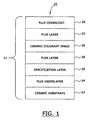
Figure 1 is a schematic representation of a printed ceramic substrate 10 that
comprises a ceramic substrate 12 onto which the color image(s) is fixed.
The ceramic substrate 12 preferably has a melting temperature of at least 550
degrees Centigrade. Such melting temperature is the temperature (or range of
temperatures) at which heterogeneous mixtures, such as a glass batch, glazes, and
porcelain enamels, become molten or softened. In one embodiment, the substrate has a
melting temperature of at least about 580 degrees Centigrade. In another embodiment,
such temperature is from about 580 to about 1,200 degrees Centigrade.
The ceramic substrate 12 preferably is a material which is subjected to a
temperature of at least about 540 degrees Celsius during processing and is comprised of
one or more metal oxides. Typical of such substrate 12 is e.g., glass, ceramic
whitewares, enamels, porcelains, etc. Thus, e.g., the substrate 12 may be dinnerware,
outdoor signage, glassware, decorative giftware, architectural tiles, color filter arrays,
floor tiles, wall tiles, perfume bottles, wine bottles, beverage containers, etc.
Referring again to Figure 1, a flux underlayer 14 is disposed on top of and
bonded to the top surface of the ceramic substrate 12. Flux underlayer 14 is preferably
transferred to the ceramic substrate surface at a coating weight (coverage) of at least
about 1 gram per square meter. It is preferred to use a coating weight (coverage) for
flux layer 14 of at least 7 grams per square meter; and it is more preferred to use a
coating weight (coverage) for layer 14 of at least about 14 grams per square meter. The
coating weight (coverage) is a dry weight, by weight of components which contain less
than 1 percent of solvent.
The coating composition used to apply layer 14 onto ceramic substrate 12 must
contain frit with a melting temperature of at least about 550 degrees Centigrade. Frit
refers to a glass which has been melted and quenched in water or air to form small
friable particles which then are processed for milling for use as the major constituent of
porcelain enamels, fritted glazes, frit chinaware, and the like.
In one embodiment, the frit used in the process of this invention has a melting
temperature of at least about 750 degrees Centigrade and, more preferably, at least
about 950 degrees Centigrade.
One may use commercially available frits. Thus, e.g., one may use a frit sold by
the Johnson Matthey Ceramics Inc. (498 Acorn Lane, Downington, Pa. 19335) as
product number 94C1001 ("Onglaze Unleaded Flux"), 23901 ("Unleaded Glass
Enamel Flux,"), and the like. One may use a flux sold by the Cerdec Corporation of
P.O. Box 519, Washington, Pa.. 15301 as product number 9630.
The melting temperature of the frit used preferably should be either substantially
the same as or no more than 50 degrees lower than the melting point of the substrate to
which the colored image is to be affixed..
The frit used in the coating composition, before it is melted onto the substrate by
the heat treatment process described elsewhere in this specification, preferably has a
particle size distribution such that substantially all of the particles are smaller than about
10 microns. In one embodiment, at least about 80 weight percent of the particles are
smaller than 5.0 microns.
One may use many of the frits known to those skilled in the art such as, e.g.,
those described in United States patents 5,562,748, 5,476,894, 5,132,165, 3,956,558,
3,898,362, and the like. Similarly, one may use some of the frits disclosed on pages 70-79
of Richard R. Eppler et al.'s "Glazes and Glass Coatings" (The American Ceramic
Society, Westerville, Ohio, 2000).
The flux underlayer 14 preferably is comprised of at least about 25 weight
percent of one or more frits, by total dry weight of all components in layer 14. In one
embodiment, from about 35 to about 85 weight percent of frit material is used in flux
underlayer 14. In another embodiment, from about 65 to about 75 percent of such frit
material is used.
It is preferred that the frit material used in layer 14 comprise at least about 5
weight percent, by dry weight, of silica. The term silica is included within the meaning
of the term metal oxide; and the preferred frits used in the process of this invention
comprise at least about 98 weight percent of one or more metal oxides selected from the
group consisting of lithium, sodium, potassium, calcium, magnesium, strontium,
barium, zinc, boron, aluminum, silicon, zirconium, lead, cadmium, titanium, and the
like.
In addition to the frit, layer 14 also is comprised of one or more thermoplastic
binder materials in a concentration of from about 0 to about 75 percent, based upon the
dry weight of frit and binder in such layer 14. In one embodiment, the binder is present
in a concentration of from about 15 to about 35 percent. In another embodiment, the
layer 14 is comprised of from about 15 to about 75 weight percent of binder.
One may use any of the thermal transfer binders known to those skilled in the
art. Thus, e.g., one may use one or more of the thermal transfer binders disclosed in
United States patent 6,127,316, 6,124,239, 6,114,088, 6,113,725, 6,083,610, 6,031,556,
6,031,021, 6,013,409, 6,008,157, 5,985,076, and the like. Thus, e.g., one may use a
binder which preferably has a softening point from about 45 to about 150 degrees
Celsius and a multiplicity of polar moieties such as, e.g., carboxyl groups, hydroxyl
groups, chloride groups, carboxylic acid groups, urethane groups, amide groups, amine
groups, urea, epoxy resins, and the like. Some suitable binders within this class of
binders include polyester resins, bisphenol-A polyesters, polvinyl chloride, copolymers
made from terephthalic acid, polymethyl methacrylate, vinylchloride/vinylacetate
resins, epoxy resins, nylon resins, urethane-formaldehyde resins, polyurethane,
mixtures thereof, etc.
In one embodiment a mixture of two synthetic resins is used as the binder.
Thus, e.g., one may use a mixture comprising from about 40 to about 60 weight percent
of polymethyl methacrylate and from about 40 to about 60 weight percent of
vinylchloride/vinylacetate resin. In one embodiment, the binder is comprised of
from 10 to 30 percent of polybutylmethacrylate and from 50 to 80 percent of the
polymethylacrylate. In one embodiment, this binder also is comprised of cellulose
acetate propionate, ethylenevinylacetate, vinyl chloride/vinyl acetate, urethanes, etc.
One may obtain these binders from many different commercial sources. Thus,
e.g., some of them may be purchased from Dianal America of 9675 Bayport Blvd.,
Pasadena, Texas 77507; suitable binders available from this source include "Dianal BR
113" and "Dianal BR 106." Similarly, suitable binders may also be obtained from the
Eastman Chemicals Company (Tennessee Eastman Division, Box 511, Kingsport,
Tennessee).
In addition to the frit and the binder, the layer 14 may optionally contain from
about 0 to about 75 weight of wax and, preferably, 5 to about 20 percent of such wax.
In one embodiment, layer 14 is comprised of from about 5 to about 10 weight percent of
such wax. Suitable waxes which may be used include carnuaba wax, rice wax,
beeswax, candelilla wax, montan wax, paraffin wax, microcrystalline waxes, synthetic
waxes such as oxidized wax, ester wax, low molecular weight polyethylene wax,
Fischer-Tropsch wax, and the like. These and other waxes are well known to those
skilled in the art and are described, e.g., in United States patent 5,776,280. One may
also use ethoxylated high molecular weight alcohols, long chain high molecular weight
linear alcohols, copolymers of alpha olefin and maleic anhydride, polyethylene,
polypopylene,
These and other suitable waxes are commercially available from, e.g., the Baker-Hughes
Baker Petrolite Company of 12645 West Airport Blvd., Sugarland, Texas.
In one preferred embodiment, carnuaba wax is used as the wax. Carnuabla wax
is a hard, high-melting lustrous wax which is composed largely of ceryl palmitate.
Reference may be had, e.g., to United States patents 6,024,950, 5,891,476, 5,665,462,
5,569,347, 5,536,627, 5,389,129, 4,873,078, 4,536,218, 4,497,851, 4,4610,490, and the
like.
Layer 14 may also be comprised of from about 0 to 16 weight percent of
plasticizers adapted to plasticize the resin used. In one embodiment, there is used from
about 1 to about 15 weight percent, by dry weight, of a plasticizer. Thus, by way of
illustration and not limitation, one may use one or more of the plasticizers disclosed in
United States patent 5,776,280 including, e.g., adipic acid esters, phthalic acid esters,
chlorinated biphenyls, citrates, epoxides, glycerols, glycol, hydrocarbons, chlorinated
hydrocarbons, phosphates, esters of phthalic acid such as, e.g., di-2-ethylhexylphthalate,
phthalic acid esters, polyethylene glycols, esters of citric acid,
epoxides, adipic acid esters, and the like.
In one embodiment, layer 14 is comprised of from about 6 to about 12 weight
percent of plasticizer which, in one embodiment, is dioctyl phthalate. The use of this
plasticizing agent is well known and is described, e.g., in United States patents
6,121,356, 6,117,572, 6,086,700, 6,060,214, 6,051,171, 6,051,097, 6,045,646, and the
like.
Disposed over flux layer 14, is opacification layer 16. Opacification layer 16 is
optional; but, when it is used, it is preferably used at a coating weight (coverage) of
from about 0.5 to about 10 grams per square meter and, more preferably, from about 1
to about 5 grams per square meter.
The opacification layer functions to introduce whiteness or opacity into the
substrate by utilizing a substance that disperses in the coating as discrete particles which
scatter and reflect some of the incident light. In one embodiment, the opacifying agent
is used on a transparent ceramic substrate (such as glass) to improve image contrast
properties.
One may use opacifying agents which were known to work with ceramic
substrates. Thus, e.g., one may use one or more of the agents disclosed in United States
patents 6,022,819, 4,977,013 (titanium dioxide), 4,895,516 (zirconium, tin oxide, and
titanium dioxide), 3,899,346, and the like. Thus, e.g., one may use opacifying agents
obtained from, e.g., Johnson Matthey Ceramic Inc., supra, as, e.g., "Superpax
Zirconium Opacifier."
The opacification agent used should preferably have a melting temperature at
least about 500 degrees Centigrade higher than the melting point of the frit(s) used in
layer 14. Generally, the opacification agent(s) has a melting temperature of at least
about 1200 degrees Centigrade.
The opacification agent should preferably have a refractive index of greater than
2.0 and, preferably, greater than 2.4.
The opacification agent preferably has a particle size distribution such that
substantially all of the particles are smaller than about 10 microns. In one embodiment,
at least about 80 weight percent of the particles are smaller than 5.0 microns.
In addition to the opacification agent, opacification layer 16 also preferably
comprises one or more thermoplastic binder materials in a concentration of from about
0 to about 75 percent, based upon the dry weight of opacification agent and binder in
such layer 14. In one embodiment, the binder is present in a concentration of from
about 15 to about 35 percent. One may use one or more of the binders described with
reference to layer 14. Alternatively, one may use one or more other suitable binders.
In addition to the opacifying agent and the optional binder, one may also utilize
the types and amounts of wax that are described with reference to layer 14, and/or
different amounts of different waxes. Alternatively, or additionally, one may also use
the types and amounts of plasticizer described with reference to layer 14. In one
embodiment, the only substantive differences between layers 14 and 16 are that the
calculations are made with respect to the amount of opacifying agent (in layer 16) and
not the amount of frit (as is done in layer 14)..
Referring again to Figure 1, one may optionally use a second flux layer 18
similar in composition and/or concentrations to layer 14. When such a second flux
layer is used, it will be disposed over and printed over the opacification layer 16.
Disposed over the flux layer 14 is one or more color images 20. These ceramic
colorant image(s) 20 will be disposed over either the ceramic substrate 12 or the flux
layer 14, and/or the optional opacification layer 16 when used, and/or the optional
second flux layer 18.
It is preferred to apply these color image(s) with a digital thermal transfer
printer. Such printers are well known to those skilled in the art and are described in
International Publication No. W0 97/00781, published on January 7, 1997. A thermal
transfer printer is a machine which creates an image by melting ink from a film ribbon
and transferring it at selective locations onto a receiving material. Such a printer
normally comprises a print head including a plurality of heating elements which may be
arranged in a line..
One may use one or more of the thermal transfer printers disclosed in United
States patents 6,124,944, 6,118,467, 6,116,709, 6,103,389, 6,102,534, 6,084,623,
6,083,872, 6,082,912, 6,078,346, and the like.
Digital thermal transfer printers are readily commercially available. Thus, e.g.,
one may use a printer identified as Gerber Scientific's Edge 2 sold by the Gerber
Scientific Corporation of Connecticut. With such a printer, the digital color image(s)
may be applied by one or more appropriate ribbon(s) in the manner discussed
elsewhere in this specification.
Referring again to Figure 1, the colorant, or colorants which form image 20 are
mixed with one or more of the ingredients listed for the opacification layer, with the
exception that the colorant(s) is substituted for the opacifying agent(s). Thus, a mixture
of the colorant and/or binder and/or wax and/or plasticizer may be used. No glass frit is
used in colorant image 20.
It is this element 20 which is selectively applied by the color printer. One such
mixture, comprised of one color, may first be digitally printed, optionally followed by
one or more differently colored mixtures. The number of colors one wishes to obtain in
element 20 will dictate how many different colors are printed.
The amount of colorant used in the composite 11 preferably should not exceed a
certain percentage of the total amount of flux used in such composite, generally being
33.33 percent or less. Put another way, the ratio of the total amount of flux in the
composite 11 (which includes layers 14, 18, and 24) to the amount of colorant in
element 20, in grams/grams, dry weight, should be at least about 2 and, preferably,
should be at least about 3. In one embodiment, such ratio is at least 4.0 In another
such embodiment, such ratio of flux/colorant is from about 5 to 6.
In another embodiment of the invention, the ratio of frit used in the process to
colorant used in the process is at least 1.25.
The unexpected results which obtain when the flux/colorant ratios of this
invention are substituted for the flux/colorant ratios of the Tanaka patent, and when the
flux and colorant layers are separated, are dramatic. A substantially more durable
product is produced by the process of the instant invention.
Furthermore, applicants have discovered that, despite the use of substantial
amounts of colorant, the process described in United States patent 5,665,472 does not
produce transferred images with good color density. Applicants believe that there is a
certain optimal amount of encapuslation and immobilization of colorant and/or
dissolution of colorant within the flux which is impeded by high concentrations of
colorant.
The colorants which work well in applicants' process preferably each contain at
least one metal-oxide. Thus, a blue colorant can contain the oxides of a cobalt,
chromium, aluminum, copper, manganese, zinc, etc. Thus, e.g., a yellow colorant can
contain the oxides of one or more of lead, antimony, zinc, titanium, vanadium, gold, and
the like. Thus, e.g., a red colorant can contain the oxides of one or more of chromium,
iron (two valence state), zinc, gold, cadmium, selenium, or copper. Thus, e.g., a black
colorant can contain the oxides of the metals of copper, chromium, cobalt, iron (plus
two valence), nickel, manganese, and the like. Furthermore, in general, one may use
colorants comprised of the oxides of calcium, cadmium, zinc, aluminum, silicon, etc.
Suitable colorants are well known to those skilled in the art. See, e.g., United
States patents 6,120,637, 6,108,456, 6,106,910, 6,103,389, 6,083,872, 6,077,594,
6,075,927, 6,057,028, 6,040,269, 6,040,267, 6,031,021, 6,004,718, 5,977,263, and the
like.
By way of further illustration, some of the colorants which can be used in the
process of this invention include those described in United States patents 6,086,846,
6,077,797 (a mixture of chromium oxide and blue cobalt spinel), 6,075,223 (oxides of
transition elements or compounds of oxides of transition elements), 6,045,859 (pink
coloring element)5,988,968 (chromium oxide, ferric oxide), 5,968,856 (glass coloring
oxides such as titania, cesium oxide, ferric oxide, and mixtures thereof), 5,962,152
(green chromium oxides), 5,912,064, 5,897,885, 5,895,511, 5,820,991 (coloring agents
for ceramic paint), 5,702,520 (a mixture of metal oxides adjusted to achieve a particular
color), and the like.
The ribbons are preferably leach-proof
and will not leach toxic metal oxide.
The particle size distribution of the colorant used in layer 20 should preferably
be within a relatively narrow range. It is preferred that the colorant have a particle size
distribution such that at least about 90 weight percent of its particles are within the
range of 0.2 to 20 microns.
The colorant used preferably has a refractive index greater than 1.4 and, more
preferably, greater than 1.6; and, furthermore, the colorant should preferably not
decompose and/or react with the molten flux when subjected to a temperature in range
of from about 550 to about 1200 degrees Celsius.
Referring again to Figure 1, a flux layer 22 optionally may be disposed over the
ceramic colorant image element 20. Thus flux layer, when used, will be comparable to
the flux layer 18 but need not necessarily utilize the same reagents and/or
concentrations. Disposed over the colorant image element 20, and coated either onto
such element 20 or the optional flux layer 22, is a flux covercoat 24.
Covercoats are described in the patent art. See, e.g., United States patents
6,123,794 (covercoat used in decal), 6,110,632, 5,912,064, 5,779,784 (Johnson Matthey
OPL 164 covercoat composition),5,779,784, 5,601,675 (screen printed organic
covercoat), 5,328,535 (covercoat for decal), 5,229,201, and the like.
The covercoat 24, in combination with the other flux-containing layers, should
preferably provide sufficient flux so that the ratio of flux to colorant is within the
specified range; and it should preferably apply structural integrity to the ceramic
colorant image element 20 so that, when composite 10 is removed from its backing
material, it will retain its structural integrity until it is applied to the ceramic substrate.
The covercoat 24 should be substantially water-insoluble so that, after it is
contacted with water at 40 degrees Centigrade for 1 minute, less than 0.5 percent of it
will dissolve.
The covercoat 24 should preferably have an elongation before break, as
measured by standard A.S.T.M. Test D638-58T, of more than 5 percent.
The covercoat 24 should be applied at a sufficient coating weight to result in a
coating weight of at least 2 grams per square meter and, more preferably, at least 5
grams per square meter.
The covercoat 24 preferably is comprised of the aforementioned flux and
carbonaceous material(s) which, in one preferred embodiment, when subjected to a
temperature of 440 degrees Centigrade for at least 5 minutes, will be substantially
completely converted to gaseous material. The aforementioned binders, and/or waxes,
and/or plasticizers described, e.g., with relation to layers 14, 16, 18, 20, 22, and 24, are
suitable carbonaceous materials, and one or more of them may be used in the
proportions described with regard to layer 14 to constitute the covercoat.
One may use a covercoat 24 which is similar in composition and structure to the
layer 14. In one embodiment, it is preferred that the covercoat 24 be comprised of a
binder selected from the group consisting of polyacrylate binders, polymethacrylate
binders, polyacetal binders, mixtures thereof, and the like.
Some suitable polyacrylate binders include polybutylacrylate, polyethyl-co-butylacrylate,
poly-2-ethylhexylacrylate, and the like.
Some suitable polymethacrylate binders include, e.g., polymethylmethacrylate,
polymethylmethacrylate-co-butylacrylate, polybutylmethacrylate, and the like.
Some suitable polyacetal binders include, e.g., polyvinylacetal, polyvinylbutyral,
polyvinylformal, polyvinylacetal-co-butyral, and the like.
Covercoat 24 preferably should have a softening point in the range of from
about 50 to about 150 degrees Centigrade.
In one embodiment, covercoat 24 is comprised of from 0 to 75 weight percent of
frit and from 25 to about 100 weight percent of a material selected from the group
consisting of binder, wax, plasticizer and mixtures thereof.
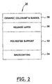
Figure 2 is a schematic representation of a preferred ribbon which may be used
in the process of this invention. It will be seen that ribbon 30 is comprised of a flexible
substrate 32.
Substrate 32 may be any substrate typically used in thermal transfer ribbons
such as, e.g., the substrates described in United States patent 5,776,280.
In one embodiment, substrate 32 is a flexible material which comprises a
smooth, tissue-type paper such as, e.g., 30-40 gauge capacitor tissue. In another
embodiment, substrate 32 is a flexible material consisting essentially of synthetic
polymeric material, such as poly(ethylene terephthalate) polyester with a thickness of
from about 1.5 to about 15 microns which, preferably, is biaxially oriented. Thus, e.g.,
one may use polyester film supplied by the Toray Plastics of America (of 50 Belvere
Avenue, North Kingstown, Rhode Island) as catalog number F53.
Thus, e.g., substrate 32 may be any of the substrate films disclosed in United
States patent 5,665,472,. Thus, e.g., one may use films of plastic such as polyester,
polypropylene, cellophane, polycarbonate, cellulose acetate, polyethylene, polyvinyl
chloride, polystyrene, nylon, polyimide, polyvinylidene chloride, polyvinyl alcohol,
fluororesin, chlorinated resin, ionomer, paper such as condenser paper and paraffin
paper, nonwoven fabric, and laminates of these materials as substrate 32.
Affixed to the bottom surface of substrate 32 is backcoating layer 34, which is
similar in function to the "backside layer" described at columns 2-3 of United States
patent 5,665,472. The function of this backcoating layer 34 is to prevent blocking
between a thermal backing sheet and a thermal head and, simultaneously, to improve
the slip property of the thermal backing sheet.
Backcoating layer 34, and the other layers which form the ribbons of this
invention, may be applied by conventional coating means. Thus, e.g., one may use one
or more of the coating processes described in United States patents 6,071,585 (spray
coating, roller coating, gravure or application with a kiss roll, air knife, or doctor blade,
such as a Meyer rod), 5,981,058 (myer rod coating), 5,997,227, 5,965,244, 5,891,294,
5,716,717, 5,672,428, 5,573,693, 4,304,700, and the like.
Thus, e.g., backcoating layer 34 may be formed by dissolving or dispersing the
above binder resin containing additive (such as a slip agent, surfactant, inorganic
particles, organic particles, etc.) in a suitable solvent to prepare a coating liquid.
Coating the coating liquid by means of conventional coating devices (such as Gravure
coater or a wire bar) may then occur, after which the coating may be dried.
One may form a backcoating layer 34 of a binder resin with additives such as,
e.g., a slip agent, a surfactant, inorganic particles, organic particles, etc.
Binder resins usable in the layer 34 include, e.g., cellulosic resins such as ethyl
cellulose, hydroxyethylcellulose, hydroxypropylcellulose, methylcellulose, cellulose
acetate, cellulose acetate buytryate, and nitrocellulose. Vinyl resins, such as
polyvinylalcohol, polyvinylacetate, polyvinylbutyral, polyvinylacetal, and
polyvinylpyrrolidone also may be used. One also may use acrylic resins such as
polyacrylamide, polyacrylonitrile-co-styrene, polymethylmethacrylate, and the like.
One may also use polyester resins, silicone-modified or fluorine-modified urethane
resins, etc.
In one embodiment, the binder comprises a cross-linked resin. In this case, a
resin having several reactive groups, for example, hydroxyl groups, is used in
combination with a crosslinking agent, such as a polyisocyanate.
In one embodiment, a backcoating layer 34 is prepared and applied at a coat
weight of 0.05 grams per square meter. This backcoating 34 preferably is
polydimethylsiloxane-urethane copolymer sold as ASP-2200@ by the Advanced
Polymer Company of New Jersey.
One may apply backcoating 34 at a coating weight of from about 0.01 to about 2
grams per square meter, with a range of from about 0.02 to about 0.4 grams/square
meter being preferred in one embodiment and a range of from about 0.5 to about 1.5
grams per square meter being preferred in another embodiment.
The substrate 32 contains an optional ribbon release layer 36 coated onto its top
surface of the substrate. The ribbon release layer 36, when used, facilitates the release
of the ceramic colorant/binder layer 38 from substrate 32 when a thermal ribbon 30 is
used to print at high temperatures.
Referring again to Figure 2, the layer 36 may be omitted and the layer 38 may be
directly contiguous with substrate 32.
Ceramic colorant/binder layer 38 is one of the layers preferably used to produce
the ceramic colorant image 20. In one embodiment, a multiplicity of ribbons 30, each
one of which preferably contains a ceramic colorant/binder layer 38 with different
colorant(s), are digitally printed to produce said ceramic colorant image 20. What these
ribbons preferably have in common is that they all contain both binder and colorant
material of the general type and in the general ratios described for layer 20. In one
embodiment, there is substantially no glass frit in layer 20 (i.e., less than about 5 weight
percent). The concentrations of colorant and binder, and the types of colorant and
binder, need not be the same for each ribbon.
Figure 3 is a schematic representation of a preferred ribbon 40 which is similar
to the ribbon 30 depicted in Figure 2 but differs therefrom in that it utilizes a flux layer
42 instead of the ceramic colorant and binder element 38. The flux layer 42, in general,
has similar components, and ratios, as the composition of flux layer 18 (see Figure 1)
and is used to deposit layer 14 and/or layer 18 and/or layer 22 onto the ceramic
substrate 12. The precise composition and coating weight of flux layer 42 will depend
upon the precise composition and coating weight of the flux layer 14 and/or flux layer
18 and/or flux layer 22 desired.
In the embodiment depicted in Figure 1, at least 4 separate flux-containing
layers are depicted. In one embodiment, it is preferred to utilize at least two such
layers. The number of layers of flux required often will depend upon how much total
flux must be used to keep the total flux/colorant ratio in composite 11 at least 2.0.
In one embodiment, it is preferred not to dispose all of the flux required in one
layer. In this embodiment, it is preferred that at least some of the flux be disposed
below the ceramic colorant image, and at least some of the flux be disposed above the
ceramic colorant image.
In one embodiment, at least 10 weight percent of the total amount of flux used
should be disposed on top of ceramic colorant image 20 in one or more flux layers (such
as layers 22 and 24). In this embodiment, at least about 50 percent of the total amount
of flux should be disposed below ceramic colorant image 20 in one or more of flux layer
18 and/or flux layer 14.
In another embodiment, from about 30 to about 70 weight percent of the entire
amount of frit used is disposed below the ceramic image 20, and from about 70 to about
30 weight percent of the entire amount of frit used is disposed above the ceramic image
20. A layer of material which contains frit need not necessarily be contiguous with the
ceramic colorant image 20 to be disposed either below or above it. Thus, e.g., and
referring to Figure 1, the flux underlayer 14 is not contiguous with the ceramic colorant
image 20 but is still disposed below such image.
In one embodiment, from about 40 to about 60 weight percent of the entire
amount of frit used in the process of this invention is disposed below the ceramic image
20, and from about 60 to about 40 weight percent of the entire amount of frit used in the
process of the invention is disposed above the ceramic image 20. In yet another
embodiment, from about 75 to about 90 weight percent of the entire amount of frit used
is disposed below the ceramic image 20, and from about 25 to about 10 weight percent
of the entire amount of frit used in the process of the invention is disposed above the
ceramic image 20
If the required amount of flux is not disposed above the ceramic colorant image
20, poor color development occurs when cadmium pigments and other pigments are
used. For non-cadmium-containing ceramic colorant images, acceptable results
utilizing a single layer of frit may be obtained so long as the single layer of frit is
positioned both above the colorant image 20 and the ceramic substrate 12 and provides
a ratio of total frit to ceramic colorant in excess of about 1.25, weight/weight.
Figures 4 is a schematic of yet another preferred ribbon 50 which is similar in
construction to the ribbons depicted in Figures 2 and 3 but differs therefrom in
containing a different arrangement of layers.
Figure 5 is a schematic of yet another preferred ribbon 52 which is similar to the
ribbons depicted in Figures 2, 3, and 4 but differs therefrom in containing a flux
covercoat layer 46. The flux covercoat layer 46 may be used to deposit the flux
covercoat 24 (see Figure 1) and, thus, should have a composition similar to the desired
covercoat 24.
Figure 6 is a schematic of yet another preferred ribbon 54 which is similar to the
other ribbons depicted but which, additionally, is comprised of opacification layer 48.
The opacification layer 48 may be used to print opacification layer 16 (see Figure 1)
and, thus, should contain substantially the same components and ratios as described for
layer 16.
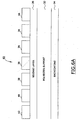
Figure 6A is a schematic representation of a another preferred ribbon 60 which
is comprised of backcoating layer 34, polyester support 32, and ribbon release layer 36.
Disposed on top of ribbon release layer 36 are a multiplicity of panels which are
disposed at selected locations on top of ribbon release layer 36. Using conventional
printing techniques, one of such panels (such as panel 42) is first coated onto ribbon
release layer 36 at the desired location, followed by selective coating of the second
panel 48, the third panel 38 etc. Although the panels 42, 48, 38, and 46 have been
shown in a particular configuration in Figure 6A, it will be apparent that other panels
and/or other configurations may be used.
To obtain such selective location(s) of the panels, one may use a gravure coating
press. What is obtained with this process is a ribbon with repeating sequences of
various panels, which thus can be utilized in a single head thermal transfer printer to
obtain a print image with multiple colors and or compositions and/or properties.
In this embodiment, it is preferred to use a sequence of 42/48/38/38/38/46 to
obtain, with printing operation, and covercoated decal which may be used to produce an
image on a ceramic substrate with good print density and good durability.
Figure 7 is a schematic representation of a ceramic decal 70, which can be
produced using one or more of the ribbons depicted in Figures 2 through 6A. The
various panels 38 shown in Figure 6A represent one or more ceramic colorant panels
used to produce a ceramic colorant image 20.
The ceramic decal 70 is preferably comprised of flexible substrate 72. This
flexible substrate 72 is often referred to as a "backing sheet" in the prior art; see, e.g.,
United States patent 5,132,165 of Blanco. Thus, e.g., substrate 72 can include a dry
strippable backing or a solvent mount or a water mount slide-off decal. The backing
may be of paper or other suitable material such as, e.g., plastic, fabric, and the like. In
one embodiment, the backing comprises paper which is coated with a release material,
such as dextrine-coated paper. Other possible backing layers include those coated with
polyethylene glycol and primary aliphatic oxyethylated alcohols.
By way of further illustration, one may use "Waterslide" paper, which is
commercially available paper with a soluble gel coat; such paper may be obtained from
Brittians Papers Company of England. This paper is also described in United States
patents 6,110,632, 5,830,529, 5,779,784, and the like.
Additionally, one may use heat transfer paper, i.e., commercially available
paper with a wax coating possessing a melt point in the range of from about 65 to about
85 degrees Centigrade. Such heat transfer paper is discussed, e.g., in United States
patents 6,126,669, 6,123,794, 6,025,860, 5,944,931, 5,916,399, 5,824,395, 5,032,449,
and the like..
It is optionally preferred that a flux layer 74 be either coated to or printed on
such paper 72. The thickness of such coating 74 should be at least about 5 microns after
such coating has dried, and even more preferably at least about 7 microns.
Referring again to Figure 7, ceramic colorant images 76 (yellow), and/or 78
(magenta) and/or 80 (cyan) and/or 82 (black) may be digitally printed by sequentially
using one or more ribbons 30. Flux layers 42 may optionally be printed by utilizing
ribbon 40, which can sequentially print layer 42 in between the various image colors.
Alternatively, layer 42 may be printed simultaneously with the image colors by the use
of ribbon 50.
The preferred ribbons depicted in Figures 2 through 6A afford one a substantial
amount of flexibility of preparing decals with many different configurations. One or
more printers equipped with one or more of such ribbons can be controlled by a
computer, which can produce a decal with substantially any desired combination of
colors, colored patterns, images, and physical properties.
Referring again to Figure 7, the flux covercoat 46 may be printed by means,
e.g., of ribbon 52.
Figure 8 is a schematic representation of a decal 80 which is similar in many
respects to decal 70 (see Figure 7) but differs therefrom in containing an opacification
layer 48 which is similar in function and composition to the opacification layer 48
depicted for ribbon 54 (see Figure 6); in another embodiment, not shown, the flux
underlayer 14 is omitted. In image 20, a multiplicity of ceramic images may be
digitally printed and superimposed on each other to form such image.
Figure 9 is a flow diagram of one preferred process for preparing a ribbon.
The process illustrated may be used to prepare ribbon 30, and/or ribbon 40,
and/or ribbon 50, etc.
In step 100, one may prepare a ceramic colorant ink in accordance with the
description, e.g., of layer 38 of Figure 2. This ink may be used to coat the faceside of
polyester support 32 in step 114 (see Figure 2).
In step 102, one may prepare a flux binder ink as described in this specification;
see, e.g., layer 42 of Figure 3 and its accompanying description. This flux binder ink
may be used to either directly coat the faceside of the polyester support 32 in step 112,
and/or coat over an optional ribbon release layer 36 in step 110.
In step 104, a ribbon release layer is prepared as described in this specification;
see, e.g., ribbon release layer 36 of Figure 2 and its accompanying description. This
ribbon release layer 36 may optionally be used in step 110 to coat the face side of the
polyester substrate 32.
In step 106, a backcoat ink may be prepared as described in this specification;
see, e.g., backcoating layer 34 of Figure 2 and its accompanying description. This
backcoat layer 34 may be used to coat the backside of the polyester substrate in step
108. In step 114, the faceside of the polyester support 32 may be coated with ceramic
colorant ink.
By using the combination of steps illustrated in Figure 9, one may readily
prepare one or more of the ribbons illustrated in Figures 2 through 5. Furthermore, one
may prepare an opacification layer in accordance with the description of opacification
layer 48 (See Figure 6 and its accompanying description) which may be used to prepare
ribbons containing such opacification layer; also see Figure 6A).
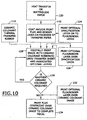
Figure 10 is a schematic diagram of a preferred process for producing a ceramic
decal. In step 120, either heat transfer or Waterslide paper is provided; these papers are
described in the specification (see element 72 of Figure 7 and its accompanying
description). A flux and binder layer is either coated or printed on the face of such
optional step 122 (see element 74 of Figure 7 and its accompanying description); and
this flux and binder layer, when dried, should be at least about 7 microns thick.
In step 124, one may optionally print an opacification layer onto the flux binder
layer described in step 122. This opacification layer corresponds to layer 48 of Figure
8. It is preferred, when such opacification layer is used in step 122, to print an optional
flux/binder layer over the opacification layer in step 126; this optional flux binder layer
is described as element 42 of Figure 8. However, as is illustrated in Figure 10, the
optional flux/binder layer may be omitted, and one may proceed directly from step 124
to step 128. Alternatively, one may omit both the opacification step and the optional
flux binder layer step and proceed directly from step 122 to 128.
It is preferred to use a ceramic colorant thermal transfer ribbon 114 in step 128.
The preparation of this ribbon was illustrated in Figure 9.
In step 128, which may optionally be repeated one or more times with different
ceramic colorant ribbons 114, a color image is digitally printed using such ribbon 114
and a digital thermal transfer printer. In one embodiment, prints were produced using a
Zebra 140XiII thermal transfer printer run at 4 inches per second with energy level
settings ranging from 18 to 24.
The digital image to be printed is preferably composed of one or more primary
colors, and such image is evaluated to determine how many printings of one or more
ceramic colorants are required to produce the desired image. Thus, in decision step 130,
if another printing of the same or a different colored image is required, step 128 is
repeated. If no such additional printing is required, one may then proceed to step 132
and/or step 134.
In optional step 132, an optional flux binder layer is printed over the ceramic
colorant image produced in step(s) 128. This optional flux binder layer corresponds to
element 42 of Figure 8. Thereafter, either one goes from step 132 to 134, or one goes
directly from decision step 130 to step 134. In printing step 134, a flux covercoat
corresponding to element 24 of Figure 8 is printed to complete the decal. One may
apply the covercoat over the entire decal (which includes both a printed image and
unprinted area[s]). Alternatively, one may apply the covercoat over the entire imaged
areas.
Thus, a complete decal is produced in Figure 10 and now may be used in
Figure 11 to produce the imaged ceramic article.
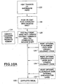
Figure 10A illustrates an alternative process for preparing a decal. The process
illustrated in Figure 10A is very similar to the process illustrated in Figure 10 with
several exceptions. In the first place, in the process of Figure 10A, in step 150 the
covercoat is applied or printed to the assembly prior to the time the ceramic colorant
image 128 is applied. Thereafter, following the application of ceramic colorant image
128, optional flux binder (step 126), and/or opacifying agent (step 124), and/or
flux/binder (step 122) may be applied to form the decal 152.
The process of Figure 10A may be used, e.g., to print a decal which thereafter
may be applied, e.g., to a wine bottle. Thus, e.g., in such an embodiment, the image is
preferably removed from the decal with hot silicone pad or a hot silicone roller.
Thereafter, the image is retransferred directly onto the ceramic article (wine bottle) and
processed as illustrated in Figure 11.
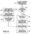
In the process depicted in Figure 11, the decal produced in step 134 of Figure 10
is treated in one of two ways, depending upon whether the substrate comprising the
decal is Waterslide or heat transfer paper.
If the substrate comprising the image is Waterslide paper, then the decal is first
soaked in hot water (at a temperature of greater than 40 degrees Centigrade. for
preferably at least about 30 seconds). In step 138, the image on the Waterslide paper is
then separated from the paper in step 140, this image is then placed onto a ceramic
substrate and smoothed to remove wrinkles or air bubbles in step 142 and dried; and
the image is then "fired." The imaged ceramic substrate is subjected to a temperature of
from about 550 to about 1200 degrees Centigrade in step 144.
If the substrate is heat transfer paper, then the decal is heated above the melting
point of the decal release layer on the paper in step 146; such temperature is generally
from about 50 to about 150 degrees Centigrade. Thereafter, while said decal release
layer is still in its molten state, one may remove the ceramic colorant image from the
paper in step 148, position the image onto the ceramic article in step 150, and then
follow steps 142 and 144 as described hereinabove.
When one wishes to make the ornamental wine bottle referred to hereinabove,
the step 148 may be accompanied with the use of the hot silicone pad and/or the hot
silicone roller described hereinabove.
A thermal transfer ribbon comprised of frosting ink
In one preferred embodiment, the thermal transfer ribbon is
used to directly or indirectly prepare a digitally printed "frost" or "frosting" on a
ceramic or glass substrate. Frosting is a process in which a roughened or speckled
appearance is applied to metal or glass. Reference may be had, e.g., to United States
patents 6,092,942, 5,844,682, 5,585,555, 5,536,595, 5,270,012, 5,209,903,
5,076,990, 4,402,704, 4,396,393, and the like. Figure 12 is a schematic
representation of one preferred thermal ribbon 200 comprised of a frosting ink layer
202. The frosting ink layer 202 is preferably comprised of from about 15 to about 94.5
weight percent of a solid, volatilizable carbonaceous binder; in one preferred
embodiment, the frosting ink layer is comprised of from about 20 to about 40 weight
percent of such solid, volatilizable carbonaceous binder.
The term carbonaceous refers to a material which is composed of carbon. The
term volatilizable refers to a material which, after having been heated to a temperature
of greater than 350 degrees Centigrade for at least 5 minutes in an atmosphere
containing at least about 15 volume percent of oxygen, will be transformed into gas and
will leave less than about 5 weight percent (by weight of the original material) of a
residue comprised of carbonaceous material.
The solid, volatilizable carbonaceous binder may be one or more of the resins,
and/or waxes, and/or plasticizers described elsewhere in this specification. Reference
may be had, for example, to the thermoplastic binders described elsewhere in this
specification.
Referring again to Figure 12, the frosting ink layer is preferably comprised of
from about 5 to about 75 weight percent of a film forming glass flux which melts at a
temperature of greater than about 550 degrees Centigrade. Such a film forming material
is able to form a continuous film when fired at a temperature of above 550 degrees
Centigrade. Reference may be had, e.g., to the frits used to form underlayer 14 (see
Figure 1) and or flux layer 18 (see Figure 1) and/or flux layer 22 (see Figure 1).
In one embodiment, the frosting ink layer is comprised of from about 35 to
about 75 weight percent of the film forming glass flux. In another embodiment, the
frosting ink layer is comprised of from about 40 to about 75 weight percent of the film
forming glass flux.
The film forming glass flux used in frosting ink layer 202 preferably has a
refractive index less than about 1.4.
In one embodiment, the film forming glass flux used in frosting ink layer 202 is
comprised of 48.8 weight percent of unleaded glass flux 23901 and 9.04 weight percent
of On Glaze Unleaded Flux 94C1001, each of which is described elsewhere in this
specification.
Referring again to Figure 12, the frosting ink layer 202 is preferably comprised
of at least about 0.5 weight percent of opacifying agent with a melting temperature of at
least 50 degrees Centigrade above the melting temperature of the film forming glass, a
refractive index of greater than about 1.4, and a particle size distribution such that
substantially all of its particles are smaller than about 20 microns. One may use one or
more of the opacifying agents described elsewhere in this specification by reference to
opacification layer 16. One may use other opacifying agents such as, e.g., Superpax
Zircon Opacifier. This and other suitable opacifying agents are described elsewhere in
this specification.
In one embodiment, from about 2 to about 25 weight percent of the opacifying
agent is used. In another embodiment, from about 5 to about 20 weight percent of the
opacifying agent is used. Thus, e.g., one may 8.17 weight percent of such Superpax
Zircon Opacifier opacifying agent.
In one preferred embodiment, it is preferred that the refractive index of the
opacifying agent(s) used in the frosting ink layer 202 be greater than about 1.4 and,
preferably, be greater than about 1.7.
The film forming glass flux(es) and the opacifying agent(s) should be chosen so
that the refractive index of the film forming glass flux material(s) and the refractive
index of the opacifying agent material(s) differ from each other by at least about 0.1
and, more preferably, by at least about 0.2. In another embodiment, the difference in
such refractive indices is at least 0.3, with the opacifying agent having the higher
refractive index.
The film forming glass flux(es) and the opacifying agent(s) used in the frosting
ink layer 202 should be chosen such that melting point of the opacifying agent(s) is at
least about 50 degrees Centigrade higher than the melting point of the film forming
glass flux(es) and, more preferably, at least about 100 degrees higher than the melting
point of the film forming glass fluxes. In one embodiment, the melting point of the
opacifying agent(s) is at least about 500 degrees Centigrade greater than the melting
point of the film forming glass flux(es). In one embodiment, the opacifying agent(s) has
a melting temperature of at least about 1,200 degrees Centigrade. It is preferred that the
weight/weight ratio of opacifying agent/film forming glass flux used in the frosting ink
layer 202 be no greater than about 1.25
Referring again to Figure 12, the frosting ink layer 202 is optionally comprised
of from about 1 to about 25 weight percent of platy particles; in an even more
preferred aspect of this embodiment, the concentration of the platy particles is from
about 5 to about 15 weight percent. A platy particle is one whose length is more than
three times its thickness. Reference may be had, e.g., to United States patents
6,277,903, 6,267,810, 6,153,709, 6,139,615, 6,124,031, 6,004,467, 5,830,364,
5,795,501, 5,780,154, 5,728,442, 5,693,397, 5,645,635, 5,601,916, 5,597,638,
5,560,983, 5,460,935, 5,457,628, 5,447,782, 5,437,720, 5,443,989, 5,364,828,
5,242,614, 5,231,127, 5,227,283, 5,196,131, 5,194,124, 5,153,250, 5,132,104,
4,548,801, 4,544,761, 4,465,797, 4,405,727, 4,154,899, 4,131,591, 4,125,411,
4,087,343, and the like.
The platy particles are preferably platy inorganic particles such as, e.g., platy
talc. Thus, by way of illustration and not limitation, one may use "Cantal 290"
micronized platy talc sold by the Canada Talc company of Marmora Mine Road,
Marmora, Ontario, Canada. This platy talc has a particle size distribution such that
substantially all of its particles are smaller than about 20 microns. Thus, e.g., one may
use, e.g., Cantal 45-85 platy particles, and/or Sierralite 603 platy particles; Sierralite
603 particles are sold by Luzenac America, Inc. of 9000 East Nicols Avenue,
Englewood, Colorado.
In one embodiment, the frosting ink layer 202 optionally contains from 0.5 to
about 25 weight percent of a colorant such as, e.g., the metal-oxide colorants referred to
in reference to ceramic colorant layer 38 (see Figure 2). It is preferred that such
optional metal oxide pigment, when used in ink layer 202, have a have a refractive
index of greater than 1.4.
The thermal ribbon 202 depicted in Figure 12 may be prepared by the means
described elsewhere in this specification. In particular, the frosting ink layer 202 is
preferably prepared by coating a frosting ink at a coating weight of from about 2.0 to
about 15 grams per square meter onto the polyester substrate. In one embodiment, the
coating weight of the frosting ink layer 202 is from about 4 to about 10 grams per
square meter.
In the embodiment depicted in Figure 12, the polyester support 32 preferably has
a thickness of from about 2.5 to about 15 microns, and the backcoat 34 preferably has a
coating weight of from about 0.02 to about 1.0 grams per square meter. A similar
ribbon 210 is depicted in Figure 13.
The ribbon 210 is substantially identical to the ribbon 200 with the exception
that it contains an undercoating layer 212. This undercoat layer 212 is preferably
comprised of at least about 75 weight percent of one or more of the waxes and
thermoplastic binders described elsewhere in this specification, and it preferably has a
coating weight of from about 0.1 to about 2.0 grams per square meter. The ribbon 210
(see Figure 13) may be prepared by means described elsewhere in this specification.
In Figure 13A, a ribbon 211 is illustrated which may be constructed in a manner
similar to that used for ribbons 200 and 210. The ribbon 211 additionally comprises
one or more covercoats 213 which are substantially free of glass frit (containing less
than about 5 weight percent of glass) and which preferably each has a coating weight of
from about 1 to about 10 grams per square meter. These covercoats 213 preferably are
comprised of at least 80 weight percent of one or more of the thermoplastic binders
described elsewhere in this specification. The thermoplastic binder material(s) used in
the covercoat(s) preferably have an elongation to break of more than about 2 percent.
In the embodiment depicted in Figure 13A, the frosting ink layer preferably has
a coat weight of from about 2 to about 15 grams per square meter, the undercoat 212
preferably has a coat weight of from about 0.2 to about 1 grams per square meter, and
the polyester substrate 32 preferably has a thickness of from about 3 to about 10
microns.
A similar ribbon 215 is depicted in Figure 13B. This ribbon is substantially
identical to the ribbon depicted in Figure 13A with the exception that it omits a
covercoat 213 disposed on top of the frosting ink layer 202.
The ribbons 200 and/or 210 and/or 211 and/or 215 may be used to prepare a
frosting decal. Thus, e.g., one such process comprises the steps of applying to a backing
sheet a covercoat comprised of a thermoplastic material with an elongation to break
greater than 2 percent and a digitally printed frosting image. The digitally printed
frosting image is comprised of a solid carbonaceous binder (described elsewhere in this
specification), and a mixture of a film forming glass flux and one or more opacity
modifying particles, wherein the difference in the refractive index between the particles
and the glass frit is at least 0.1 and the melting point of the particles is at least 50
degrees Centigrade greater than that of the film forming glass flux.
The backing sheet used in this process may be typically polyester or paper.
Alternatively, or additionally, the backing sheet may comprise or consist of cloth,
flexible plastic substrates, and other substrates such as, e.g., substantially flat materials.
When paper is used in this embodiment, it is preferred that similar in composition to
the papers described elsewhere in this specification.
Figure 14 is a schematic representation of one preferred heat transfer paper 220
made with the thermal ribbon of Figure 12 or Figure 13. A decal release layer 220 may
be coated onto paper 226 by means described elsewhere in this specification. This decal
release layer 220 preferably has a thickness of from about 0.2 to about 2.0 microns
and typically is comprised of at least about 50 weight percent of wax.
In one embodiment, the decal release layer 220 is comprised of at least about 50
weight percent of wax. Suitable waxes which may be used include carnuaba wax, rice
wax, beeswax, candelilla wax, montan wax, paraffin wax, mirocrystalline waxes,
synthetic waxes such as oxidized wax, ester wax, low molecular weight polyethylene
wax, Fischer-Tropsch wax, and the like. These and other waxes are well known to
those skilled in the art and are described, e.g., in United States patent 5,776,280.
In one embodiment, at least about 75 weight percent of layer 220 is comprised
of wax. In this embodiment, the wax used is preferably carnuaba wax. Minor amounts
of other materials may be present in layer 220. Thus, one may include from about 5 to
about 20 weight percent of heat-softening resin which softens at a temperature of from
about 60 to about 150 degrees Centigrade. Some suitable heat-softening resins include,
e.g., the heat-meltable resins described in columns 2 and of United States patent
5,525,403.
In one embodiment, the heat-meltable resin used is polyethylene-co-vinylacetate
with a melt index of from about 40 to about 2500 dg. per minute.
In one embodiment the release layer 220 is produced by extrusion coating a
polyethylene and wax mixture to a coatweight of 20 grams per square meter.
In one embodiment, the release layer 220 need not necessarily comprise wax.
The release layer 220, in this embodiment, does preferably comprise a material that,
when coated upon a substrate, provides a smooth surface with a surface energy of less
than about 35 dynes per centimeter.
In one embodiment, the release layer 220 is comprised of a polyolefin, such as,
e.g., polyethylene, polypropylene, polybutylene, and mixtures thereof.
In one embodiment, it is preferred to coat the release layer 220 onto a substrate
by means of extrusion, at a temperature of from about 200 to about 300 degrees Celsius.
Extrusion coating of a resin is well known. Reference may be had, e.g., to United States
patents 5,104,722, 4,481,352, 4,389,445, 5,093,306, 5,895,542, and the like.
It is preferred that the release layer coating 220 be substantially smooth. In one
embodiment, the coated substrate has a Sheffield smoothness of from about 10 to about
150 and, more preferably, from about 10 to about 40 Sheffield Units. Means for
determining Sheffield smoothness are well known. Reference may be had, e.g., to
United States patents 5,451,559, 5,271,990 (image receptor heat transfer paper),
5,716,900, 6,332,953, 5,985,424, and the like.
The release layer may be of any composition that will produce the desired
surface energy and smoothness upon coating the substrate. Thus, by way of illustration
and not limitation, one may utilize a cured silicone release layer. Release layers
comprised of silicone are well known. Reference may be had, e.g., to United States
patents 5,415,935 (polymeric release film), 5,139,815 (acid catalyzed silicone release
layer), 5,654,093, 5,761,595, 5,543,231 (radiation curable silicone release layer), and
the like.
By way of further illustration, one may use fluoropolymer release agents See,
e.g., United States patents 5,882,753 (extrudable release coating), 5,807,632,
6,248,435, and the like.
In one embodiment, decal release layer 220 is a resin release layer. Suitable
resins may be selected from the class of thermoplastic polymers which can be coated
into smooth layers with surface energies less than 0.4 mN/cm (40 dynes/cm). In one embodiment, the
resin release layer may be comprised of polyethylene, polypropylene, polybutylene and
the like.
Referring again to Figure 14, a covercoat layer 224 is disposed above a paper
substrate 226. The covercoat layer 224 preferably is comprised of at least 25 weight
percent of one or more of the aforementioned thermoplastic materials with an
elongation at break greater than about 2 percent. In one embodiment, the covercoat
layer 224 is comprised of at least about 50 weight percent of such thermoplastic
material.
In the embodiments depicted in Figures 13, 13A, 13B, 14, 15, and 16, the
covercoat layers 213 and/or 224 contain less than about 5 weight percent of glass frit.
In another embodiment, such covercoat layers contain less than about 1 weight percent
of glass frit.
In one embodiment, the covercoat layer 224 is comprised of a thermoplastic
material with an elongation at break of at least about 5 percent.
Suitable thermoplastic materials which may be used in covercoat layer 224
include, e.g., polyvinylbutyral, ethyl cellulose, cellulose acetate propionate,
polyvinylacetal, polymethylmethacrylate, polybutylmethacrylate, and mixtures thereof.
After the covercoat layer 224 has been applied, the frosting ink image 222 may
be digitally applied with the use of either the ribbon 200 and/or the ribbon 210 and/or
the ribbon 211 and/or the ribbon 215.
Figure 15 is a schematic representation of a Waterslide assembly 230 which is
similar to the heat transfer paper 220 but differs therefrom in several respects. In the
first place, the decal release layer 220 is replaced by the water soluble gel layer 228;
in the second place, the paper 226 is replaced by the Waterslide paper substrate 229.
Waterslide paper is commercially available with soluble gel coating 228.
The Waterslide paper assembly (elements 229 and 228), in the embodiment
depicted in Figure 15, is first coated with covercoat layer 224 at a coat weight of from
about 2 to about 20 grams per square meter and then digitally printed with frosting ink
image 222.
Figure 16 is a schematic representation of a transferable covercoat assembly
240, which is comprised of paper substrate 226, transferable covercoat paper 242, and
frosting ink image 222.
The aforementioned description is illustrative only and that changes can be made
in the ingredients and their proportions, and in the sequence of combinations and
process steps, as well as in other aspects of the invention discussed herein.
In one embodiment the decorated ceramic article 10 depicted in Figure 1
comprises a ceramic or glass substrate 12 on which a ceramic colorant image 20 is
disposed. A similar ceramic glass substrate 300 is depicted in Figure 19. In both cases
the ceramic/glass substrate 12 is fired to either sinter it or to cause the materials
disposed on it to adhere to it. When such firing occurs, the frit in layers 224 melts and
reforms as glass. Thus, after such firing, the ceramic colorant image 20 of Figure 1 and
the frosting ink image 222 of Figure 19 are disposed between two glass layers.
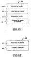
Thus, e.g., Figure 19 depicts a coated ceramic/glass substrate 301 which is
similar to the coated substrate assembly 10 but differs therefrom in having a covercoat
213/frosting ink image 222/covercoat layer 213 disposed over the substrate 12..
Thus, e.g., other structures may be formed in which, e.g., the frosting ink image
222 is disposed between two glass layers. Thus, e.g., and in the process depicted in
Figure 20, one may print a frosting ink image 222 onto a thermoplastic substrate 302
with the use of a ribbon 200, 210, 211, and/or 215. One may use a substrate such as,
e.g., a sheet of biaxially oriented poly(ethyelene terephthalate), a sheet of polyvinyl
chloride, a sheet of polycarbonate, etc. The digitally printed thermoplastic substrate
may then be attached to a first pane of ceramic or glass material and, thereafter, the
assembly thus formed may be attached to a second pane of ceramic or glass material to
form a ceramic(glass)/thermoplastic sheet/ceramic(glass) laminate.
Figure 21 discloses a structure 305 in which the coated flexible substrate 303 is
attached to a ceramic/glass substrate 12. It is preferred not to fire this structure, because
the gases evolved from the flexible substrate layer 302 may degrade the frosting ink
layer 305.
Figure 22 depicts a laminated structure 307 in which the assembly 303 is
sandwiched between two ceramic/glass substrates 12 to form a laminated structure.
Figure 23 shows a structure which is similar to that of Figure 21 but that can be
fired without substantially degrading the structural integrity of frosting ink image 222.
A process for making a ceramic decal assembly
Figure 24 is a flow diagram of one preferred process of the invention. In step
400 thereof, a decal is prepared which can thereafter be adhesively attached to a
ceramic/glass substrate. The decal to be prepared is preferably a digitally printed decal
whose preparation is described elsewhere in this specification.
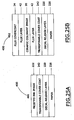
Thus, e.g., and referring to Figures 25A and 25B, one may prepare ceramic
decal 401 and/or ceramic decal 402. When these embodiments are used, it is preferred
that they comprise, in one preferred aspect of this embodiment, an "ethocel coated heat
transfer paper." This term as used herein refers to heat transfer paper, i.e.,
commercially available paper with a wax coating possessing a melt point in the range of
from about 65 to about 85 degrees Centigrade which is coated with a layer of
ethylcellulose which, in one embodiment, is about 10 grams/square meter thick. Such
heat transfer paper is discussed, e.g., in United States patents 6,126,669, 6,123,794,
6,025,860, 5,944,931, 5,916,399, 5,824,395, 5,032,449, and the like.
What each of decals 401 and 402 preferably have in common is a substrate 226.
This substrate 226, which is typically paper, is described elsewhere in the specification.
However, this substrate may be any type of flat, thin, flexible sheet, for example,
polyester or polyolefin films, non-woven sheets and the like. The substrate for the
decal should first be coated with a decal release layer 220 and then a covercoat layer.
The covercoated substrate should have the characteristics of being able to receive a
thermally printed digital image from the various thermal transfer ribbons described
elsewhere in this specification. After printing onto such coated substrates, a ceramic
decal is formed. A further characteristic of the these decals is that, after the decal has
been attached to the glass or ceramic substrate, the substrate on which the decal was
formed should be able to be cleanly separated from the image. This separation should
occur between the decal release layer 220 layer and the covercoat such that the
covercoat and the image remain entirely on the glass and ceramic substrate.
Each of the decals 401 and 402 preferably has a decal release layer 220 in
common. This decal release layer 220 preferably has a thickness of from about 0.2 to
about 2.0 microns and in one embodiment is comprised of at least about 50 weight
percent of wax.
Each of the decals 401 and 402 also comprise a transferable covercoat layer 242.
In one embodiment, the transferable covercoat layer 242 is comprised of ethylcellulose.
Such a covercoat is prepared by dissolving 12 grams of ethylcellulose with a mixture of
16.4 grams of isopropyl alcohol, 68.17 grams of toluene, and 3.42 grams of dioctyl
pthalate that has been heated to 50 degrees Celsius. This solution thus formed is then
applied to a decal release layer 220 coated substrate with a Meyer rod to achieve a
coating weight of about 10 grams/square meter. Thus, e.g., the transferable covercoat
layer 242 may have the same composition as covercoat layer 224 (see Figure 14) and/or
covercoat layer 24. In this embodiment, covercoat layer 242 is comprised of at least
about 25 weight percent of thermoplastic material with an elongation to break of greater
than about 2 percent. In one embodiment, the covercoat layer 242 is comprised of at
least about 50 weight percent of thermoplastic material with an elongation at break of
greater than 2 percent. In another embodiment, the covercoat layer 242 is comprised of
thermoplastic material with an elongation at break greater than 5 percent.
In each of the decals 401 and 402, disposed above the transferable covercoat
layer 242 is either a frosted ink image 222 (decal 401), or a ceramic colorant image 20.
What each of these image layers preferably has in common with the other is the
presence of either opacification particles or colorant particles that have a particle size
distribution such that at least about 90 weight percent of such particles are within the
range of from about 0.2 to about 20 µm. In addition, both of these images must be
comprised of film forming glass flux. The aforementioned opacification particles or
colorant particles should preferably have a refractive index of at least about 0.1 and
preferably 0.2 units different from the refractive index of the film forming glass flux
used in the image. In addition, the aforementioned opacification particles or colorant
particles as well as the glass flux should be non-carbonaceous in their combination and
essentially inorganic such that they remain on the glass or ceramic substrate after firing.
Both of these images must also have the capability to alter the visual appearance of the
glass or ceramic substrates, in an image-wise fashion, after the substrates have been
fired to visually reveal the intended decoration of said substrates.
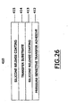
Referring again to Figure 24, and in step 410 thereof, a pressure sensitive
transfer adhesive assembly is prepared. As is indicated in Figure 26, the pressure
sensitive transfer adhesive assembly is comprised of pressure sensitive transfer
adhesive. These adhesives, and assemblies comprising them, are well known to those in
the art. Reference may be had, e.g., to United States patents 5,319,475, 6,302,134,
reissue 37,036, 6,063,589, 5,623,010, 5,059,964, 5,602,202, 6,284,338, 6,134,892,
5,931,000, and the like. Reference may be had, e.g., to United States patent applications
20010001060A1, 20020015836A1, and the like. Reference may be had to
international patent publications EP0530267B1, EP0833965B1, EP0833866B1,
WO9700922A1, WO9700913A1, EP0576530B2, and the like.
Pressure sensitive adhesives are also described at, e.g., pages 724-735 of Irving
Skeist's "Handbook of Adhesives," Second Edition (Van Nostrand Reinhold Company,
New York, New York, 1977). These adhesives are often composed of a rubbery type
elastomer combined with a liquid or solid resin tackifier component.
Pressure-sensitive acrylic adhesives are often used. The acrylate pressure-sensitive
adhesives are often a copolymer of a higher alkyl acrylate, such as, e.g., 2-ethylehexyl
acrylate copolymerized with a small amount of a polar comonomer.
Suitable polar comonomers include, e.g., acrylic acid, acylamide, maleic anhydride,
diacetone acrylaminde, and long chain alkyl acrylamides.
In one preferred embodiment, the pressure sensitive transfer adhesive is an
acrylic pressure sensitive transfer adhesive. These adhesives are also well known.
Reference may be had, e.g., to United States patents 5,623,010 (acrylate-containing
polymer blends and methods of using), 5,605,964, 5,602,202 (methods of using
acrylate-containing polymer blends), 6,134,892, 5,931,000, 5,677,376 (acrylate-containing
polymer blends), 5,657,516, and the like.
One suitable pressure sensitive transfer adhesive assembly is sold as "Arclad
7418" by Adhesives Research, Inc. of 400 Seaks Run Road, Glen Rock, Pennsylvania.
This assembly is comprised of an acrylic adhesive and a densified kraft liner.
Other laminating adhesive assemblies also may be used in the process of this
invention. Reference may be had, e.g., to United States patents 5,928,783 (pressure
sensitive adhesive compositions), 5,487,338, 5,339,737, and the like. Reference may
also be had to European patent publications EP0942003A1, EP0684133B1,
EP0576128A1, and the like.
Referring again to Figure 26, and in the preferred embodiment depicted therein,
the pressure sensitive adhesive assembly 410 is comprised of pressure sensitive
adhesive 412, silicone release coating 413, transfer substrate 414, and silicone release
coating 415. The adhesive assembly 410 preferably has a thickness 416 of less than
about 100 microns, preferably being from about 1 to about 20 microns thick. More
preferably, the adhesive assembly 410 has a thickness 416 from about 0.1 to about 2
microns thick.
In one embodiment, the pressure sensitive transfer adhesive is comprised of at
least 95 weight percent of carbonaceous material and less than about 5 weight percent of
inorganic material.
Referring again to Figure 24, and in step 420 of the process, the decal provided
in step 400 and the pressure-sensitive transfer adhesive assembly provided in step 410
are pressure laminated to form a composite laminated structure (see Figure 27). This
pressure lamination process is well known to those skilled in the art. Reference may be
had, e.g., to United States patents 6,120,882, 5,866,236, 5,656,360, 5,100,181,
5,124,187, 6,270,871, 5,397,634, and the like.
In the preferred embodiment depicted in Figure 27, the composite assembly is
pressure laminated with pressure rollers 425, preferably using a light pressure of less
than about 7 kPa (1 pound per square inch). It is preferred to remove substantially all air and/or
other gases between adjacent contiguous surfaces in this process.
Referring again to Figure 24, and in step 430 thereof, the release paper
(comprised of the transfer substrate 414, with silicone release coatings 413/415 on its
opposed surfaces) is stripped away from the pressure sensitive adhesive 412 to form a
pressure-sensitive adhesive decal. This process step 430 is schematically illustrated in
Figure 28.
Referring again to Figure 24, and in step 440 thereof, the pressure sensitive
adhesive decal is laminated to either a glass or a ceramic substrate with light pressure
(less than about 7 kPa (1 pound per square inch)) by pressure lamination; reference may be had
to Figure 29, wherein this step 440 is schematically illustrated.. This step 440 will leave
the paper 226 and the decal release layer 220 indirectly attached to the glass or ceramic
substrate 12. Alternatively, the glass or ceramic article may be directly coated or
laminated with a pressure sensitive adhesive. Such an article may then be directly
laminated to the decal as in Step 440, eliminating Steps 420 and 430.
Thereafter, and referring again to Figure 24, in step 450 the wax/resin coated
paper or substrate 226 is peeled away from the covercoat 242 of the ceramic decal
assembly. The assembly that remains after this step is illustrated in Figure 31.
The assembly depicted in Figure 31 is comprised of a frosted ink image 222; this
will be obtained when decal 401 is used (see Figure 25A). When decal 402 is used (see
Figure 25B), a ceramic colorant image 20 will be obtained.
In step 460, the ceramic/glass assembly is then fired to burn off substantially all
of the carbonaceous material in the assembly. In general, the assembly is subjected to a
temperature of from at least about 350 degrees Centigrade for at least about 5 minutes.
Thereafter, in step 470 of the process (see Figure 24), the fired substrate is
measured to determine its optical quality. The optical quality of a fired substrate may
be determined, e.g., by comparing the optical density of the image on the fired substrate
with the optical density of the image on the unfired substrate.
Applicants' process unexpectedly produces a fired product whose optical
properties are substantially as good as, if not identical to, the optical properties of the
unfired product.
As is illustrated in Figure 32, the unfired substrate assembly 473 is analyzed by
optical analyzer 471. Thereafter, the fired substrate assembly 475 is analyzed by optical
analyzer 471. The optical properties of the fired substrate 475 are preferably at least
about 80 percent as good as the optical properties of the unfired substrate 473.
In one embodiment, a pattern recognition algorithm (not shown) is used to
compare the unfired image on assembly 473 to the fired image on assembly 475. The
use of pattern recognition algorithms for the purpose is well known. Reference may be
had, e.g., to United States patents 6,278,798 (image object recognition), 6,275,559,
6,195,475, 6,128,561, 5,024,705, 6,017,440, 5,838,758, 5,264,933, 5,047,952,
5,040,232, 5,012,522 (automated face recognition), and the like.
One or more matching algorithms may be used to compare these optical
qualities. These algorithms, and their uses, are well known. See, e.g., United States
patents 6,041,137 (handwriting definition), 5,561,475, 5,961,454, 6,130,912,
6,128,047, 5,412,449, 4,955,056 (pattern recognition system), 6,031,980, 5,471,252,
5,875,108, 5,774,357, and the like.
In one embodiment, illustrated in Figure 32, when the substrate 12 is a clear
substrate (such as, e.g., glass), one may measure and compare the transmission density
of the unfired and fired optical images by means of, e.g., a densitometer. In another
embodiment, illustrated in Figure 32, when the substrate 12 is an opaque substrate, one
may measure and compare the reflection density of the unfired and fired optical images
by means of, e.g., a densitometer. Such uses of a densitometer are well known.
Reference may be had, e.g., to United States patents 3,614,241 (automatic recording
densitometer which simultaneously determines and records the optical density of a strip
of photographic film), 5,525,571, 5,118,183, 5,062,714, and the like.
Referring again to Figure 32, and in particular to fired assembly 475, it will be
seen that, in the embodiment depicted, in areas 477, 479, 481, and 483 some or all of the
image has been eroded during the firing. Applicants believe that this erosion can occur
when gases are formed during the firing and disrupt the layer 22 as they escape from the
fired assembly.
Regardless of the cause of such erosion, its existence damages the optical
properties of the fired substrate. The process of the instant invention produces a product
in which such erosion is substantially absent.
The following examples are presented to illustrate the claimed invention but are
not to be deemed limitative thereof. Unless otherwise specified, all parts are by weight,
and all temperatures are in degrees Centigrade.
Example 1
A 4.5 µm thick poly (ethylene terephthalate) film (Toray F31) was used as a
substrate film, and it was backcoated with a polydimethylsiloxane-urethane copolymer
SP-2200 crosslinked with D70 toluene diisocyanate prepolymer (both of which were
sold by the Advanced Polymer Company of New Jersey) at a coat weight of 0.03 grams
per square meter. The copolymer composition was applied with a Myer Rod and dried
in an oven at a temperature of 50 degrees Centigrade for 15 seconds.
A ribbon release coating composition was prepared for application to the face
coat of the polyester film. A first mixture, mixture #1, was prepared by dissolving 3.5
grams of Therban LT 2157 ( a acrylonitile butadiene rubber sold by The Bayer
Corporation of Morristown, New Jersey) into 46.5 grams of toluene that had been
heated to a temperature of 70 degrees Centigrade. A second mixture, mixture #2, was
then prepared by adding 12.62 grams of Polywax 850 ( a polyethylene wax sold by
Baker Hughes Petrolite Company of Sugarland, Texas ) to 71.51 grams of toluene; the
composition thus produced was mixed with 50 grams of ceramic grinding media and
milled on a paint shaker for 15 minutes until substantially all of the particles were
smaller than 10 µm. A third mixture, mixture #3, was prepared by heating 23.72
grams of toluene to a temperature of 70 degrees Centigrade, then adding 3.78 grams of
Evaflex 577 ( an ethylene-vinylacetate resin sold by DuPont Mitsui and Polychemicals
Company of Japan) until dissolved, then adding 4.62 grams of Ceramer 1608 ( a alpha-olefinic
wax sold by Baker Hughes Petrolite Company of Sugarland, Texas ), then
mixing until fully dissolved, and then reducing the temperature of the mixture #3 to 50
degrees Centigrade. Finally, an ink was prepared by adding 23.74 grams of mixture #1
and 32.12 grams of Mixture #3 to Mixture #2. Thereafter the mixture so produced was
filtered to separate the filtrate from the grinding media, and the filtrate was then coated
onto the polyester substrate at a coating weight of 0.75 grams per square meter using a
Meyer Rod. The coated substrate thus produced was then dried with hot air.
The polyester film, with its backcoating and ribbon release coating, then was coated
with a frosted ink layer at a coating weight of 5.6 grams per square meter; the frosted
ink layer was applied to the ribbon release layer. The frosted ink was prepared by
mixing 60.0 grams of hot toluene (at a temperature of 60 degrees Centigrade) with
14.73 grams of a mixture of Dianal BR 106 and Dianal BR 113 binders in
weight/weight ratio of 1/3; these binders were purchased from the Dianal America
Company of Pasadena, Texas. Thereafter, 3.99 grams of dioctyl pthalate ( sold by
Eastman Chemical, Kingsport, TN), 48.8 grams of Unleaded Glass Flux 23901 (sold by
Johnson Matthey Ceramic Inc. of Downington, Pa.) with a refractive index of 1.4, 9.04
grams of Onglaze Unleaded Glass Flux 94C1001 (sold by Johnson Matthey Ceramic
Inc. of Downington, Pa) with a refractive index of 1.7, 8.17 grams of Superpax Zircon
Opacifier (sold by Johnson Matthey Ceramic Inc. of Downington, Pa.) with a refractive
index of 1.9, 8.17 grams of Cantal 290 (sold by Canada Talc, Marmora, Ontario,
Canada), and 1.59 grams of Cerdec 1795 Black Oxide (sold by Cerdec-DMC2,
Washington, Pa) were charged to the mixture. The composition thus produced was
mixed with 50 grams of ceramic grinding media and milled on a paint shaker for 15
minutes until substantially all of the particles were smaller than 10 µm. Thereafter,
5.48 grams of Unilin 425 (a wax sold by the Baker Hughes Baker Petrolite Company)
were dissolved in sufficient reagent grade methylethylketone to prepare a 15 percent
solution, and this wax solution was then charged to the mixture with stirring, until a
homogeneous mixture was obtained. Thereafter the mixture was filtered to separate the
filtrate from the grinding media, and the filtrate was then coated onto the ribbon release
layer of the polyester substrate at a coating weight of 5.6 grams per square meter using a
Meyer Rod. The coated substrate thus produced was then dried with a hot air gun.
A covercoated backing sheet was prepared by coating a 12% solution of ethylcellulose
(supplied by Dow Chemical of Midland Michigan) in toluene onto a heat transfer
backing sheet (supplied by Brittains Papers, Stokes-on-Trent, United Kingdom) with a
Meyer Rod to achieve a dry coating weight of 10.0 grams per square meter. The coating
was dried with a hot air gun.
Thereafter a rectangular, solid fill image was printed onto the covercoated backing
sheet with the frosting ribbon using a Zebra 140xi printer at an energy setting of 22 and
a print speed of 10 centimeters per second to prepare a frosting ink decal.
The frosting ink image was then transferred to a sheet of borosilicate glass (10
centimeters x 10 centimeters x 0.5 centimeters) by pressing the frosting ink decal
against the glass sheet and heating this composite up to a temperature of 121 degrees
Centigrade. The backing sheet was then peeled away from the glass sheet, leaving the
frosting ink image on the glass. The glass and frosting ink image were then fired in a
kiln for 20 minutes at 340 degrees Centigrade. This thermal treatment caused the
carbonaceous binder in the frosting image to burn away, leaving the mixture of film
forming glass frit and opacifying agents on the glass sheet. The heat of the kiln also
caused the film forming glass frit to melt and flow into a film on the surface of the glass
sheet. The opacifying agents remained dispersed in this film, thus rendering the film
translucent yet not transparent.
The frosting ink image was then characterized for whiteness and opacity. The test for
determining opacity was carried out according to the Tappi Standard T519. The
measurements were taken on fired glass samples. The whiteness was calculated
according to CIE Lab color space measurement standard of 1976 with a D65 illuminate
and a 10 degree observation angle.
In the experiment of this example, the combination of Unleaded Glass Flux with a
refractive index of 1.4, Onglaze Unleaded Glass Flux with a refractive index of 1.7 and
Superpax Zircon Opacifier with a refractive index of 1.9 was fired into a frosting image
on the glass sheet with an opacity value of 52 and a whiteness of 20.06 delta L*.
Example 2
A pressure sensitive adhesive was prepared from a 20 percent solution of an
acrylic polymer, Dianal BR106 (a methyl n-butyl methacrylate copolymer, supplied by
Dianal America, Pasadena, Texas) in toluene was prepared. To 100 grams of this
solution was added 10 grams of dioctyl pthalate (sold by Eastman Chemical of
Kingsport, Tennessee). This solution was then coated onto a glass substrate using a
Meyer rod at a coatweight of 3.98 grams per square meter to form a pressure sensitive
adhesive coated glass substrate.
A decal was then prepared as described in accordance with the procedure of
Example 1 . This decal was then placed face side down onto the pressure sensitive
adhesive coated glass substrate(10 centimeters x 10 centimeters x 0.5 centimeters).
Pressure was applied at 1 pound per square inch to the backside of the decal for 15
seconds to affix the decal to the glass substrate . The backing sheet was then peeled
away from the glass sheet, leaving the frosting ink image and associated covercoat
affixed to the glass. The glass and frosting ink image were then fired in a kiln for 20
minutes at 340 degrees Centigrade. This thermal treatment caused the carbonaceous
binder in the frosting image to burn away, leaving the mixture of film forming glass frit
and opacifying agents on the glass sheet.
The opacity of the unfired decal assembly was 38.23. The opacity of the fired
decal assembly was 38.22, being substantially unchanged
Example 3
The procedure of Example 2 was substantially followed, with the exception that
the glass substrate was coated with the same acrylic pressure sensitive adhesive solution
using a meyer rod to achieve a coatweight of 16.34 grams per square meter.
A decal was prepared, attached to the pressure sensitive adhesive coated glass
substrate and fired essentially in the same fashion as described in Example #2. The
opacity of the unfired decal assembly was 38.67. The opacity of the fired decal
assembly was 38.18