EP1336886A2 - Telecentric system and image measuring device - Google Patents
Telecentric system and image measuring device Download PDFInfo
- Publication number
- EP1336886A2 EP1336886A2 EP03000585A EP03000585A EP1336886A2 EP 1336886 A2 EP1336886 A2 EP 1336886A2 EP 03000585 A EP03000585 A EP 03000585A EP 03000585 A EP03000585 A EP 03000585A EP 1336886 A2 EP1336886 A2 EP 1336886A2
- Authority
- EP
- European Patent Office
- Prior art keywords
- numerical aperture
- lens unit
- lens system
- diaphragm
- telecentric
- Prior art date
- Legal status (The legal status is an assumption and is not a legal conclusion. Google has not performed a legal analysis and makes no representation as to the accuracy of the status listed.)
- Withdrawn
Links
Images


Classifications
-
- G—PHYSICS
- G02—OPTICS
- G02B—OPTICAL ELEMENTS, SYSTEMS OR APPARATUS
- G02B13/00—Optical objectives specially designed for the purposes specified below
- G02B13/22—Telecentric objectives or lens systems
-
- G—PHYSICS
- G02—OPTICS
- G02B—OPTICAL ELEMENTS, SYSTEMS OR APPARATUS
- G02B26/00—Optical devices or arrangements for the control of light using movable or deformable optical elements
- G02B26/02—Optical devices or arrangements for the control of light using movable or deformable optical elements for controlling the intensity of light
-
- G—PHYSICS
- G02—OPTICS
- G02B—OPTICAL ELEMENTS, SYSTEMS OR APPARATUS
- G02B5/00—Optical elements other than lenses
- G02B5/005—Diaphragms
Definitions
- the present invention relates to a telecentric lens system and an image measuring device.
- the double telecentric lens system comprises two lens units, a front lens unit and a rear lens unit, with the back focal point of the front lens unit and the front focal point of the rear lens unit being disposed so that they coincide, and a diaphragm disposed at the location where these two focal points coincide.
- the telecentric lens system In the double telecentric lens system, the field of view of an object is wide, the focal depth is large, and the imaging magnification is determined by the focal lengths of the front lens unit and the rear lens unit regardless of the position of the object. Therefore, the telecentric lens system is frequently used to observe objects having stepped portions, such as edge tools, mechanical parts, and assembled electronic parts.
- the resolution and the focal depth are inversely proportional to each other. In other words, when the focal depth is increased, the resolution is reduced.
- separately providing a lens or a microscope is costly.
- a telecentric lens system comprising a front lens unit; a rear lens unit which is disposed so that the front focal point of the rear lens unit coincides with the back focal point of the front lens unit; and a diaphragm mechanism which is disposed at the location where the back focal point of the front lens unit and the front focal point of the rear lens unit coincide, and which comprises a numerical aperture changer for changing the numerical aperture of the diaphragm mechanism.
- the diaphragm mechanism comprises a numerical aperture changer
- the numerical aperture can be changed.
- the focal depth and the resolution are inversely proportional to each other.
- the numerical aperture is reduced by the numerical aperture changer, the resolution is low, but the focal depth is large. In other words, an object having a stepped portion can be observed clearly and measured.
- the numerical aperture is increased by the numerical aperture changer, the focal depth becomes small, but the resolution is high. In other words, an object can be observed and measured with precision and high resolution.
- the telecentric lens system can be used in a wide range of applications from those requiring a large focal depth to those requiring high resolution. Therefore, one telecentric lens system can be successively used for observations for different applications. As a result, operation efficiency is remarkably increased. In addition, since it is not necessary to separately provide, for example, a microscope according to the type of application, costs can be reduced.
- the numerical aperture changer has at least two diaphragms having numerical apertures that differ successively, and, by changing one diaphragm with another diaphragm, the numerical aperture is changed.
- the numerical aperture can be changed by changing a diaphragm with one having a different numerical aperture. Therefore, one telecentric lens system can be successively used for observations for different applications (such as, applications requiring large focal depths or high resolution) . As a result, operation efficiency can be increased. In addition, since it is not necessary to separately provide a microscope, costs can be reduced.
- optical features such as focal depth and resolution
- optimal numerical apertures can be easily selected according to various objects to be observed and various applications. Since the optical features are known when, for example, an observed image is processed and measured, the image can be optimally measured.
- the diaphragms are successively provided in one plate, and, by moving the plate, the numerical aperture is changed.
- the diaphragms may be provided in one row in one plate or along the circumference of one plate. According to such a structure, the numerical aperture can be changed by moving the plate. Therefore, the structure is simple, and observations for different applications can be successively carried out using one telecentric lens system by only simply moving the plate, so that operation efficiency can be increased.
- the diaphragms are provided in swingably supported levers, respectively, and, by movement of any one of the levers, the numerical aperture is changed.
- levers be provided perpendicular to the optical axis and be supported so that they swing within a plane that is perpendicular to the optical axis.
- levers having different numerical apertures be disposed along the optical axis.
- the numerical aperture changer comprises an iris diaphragm for successively changing the numerical aperture.
- the numerical aperture can be successively changed. Since the numerical aperture can be successively changed, the numerical aperture can be adjusted to an optimal numerical aperture according to the type of application. Therefore, observations for different applications, such as an observation requiring a large focal depth or that requiring a high resolution, can be successively carried out using one telecentric lens system. As a result, operation efficiency can be increased. Since it is not necessary to separately provide a microscope according to the type of application, costs can be reduced.
- either the front lens unit or the rear lens unit is changeable.
- the numerical aperture changer by the numerical aperture changer, observations ranging from those requiring a large focal depth to those required high resolution can be carried out.
- the setting range of focal depths and the setting range of resolutions can be increased.
- the focal depth and the resolution are uniquely determined for one lens unit. Therefore, in order to provide a wide range of focal depths and resolutions, it is necessary to provide a large number of lens units.
- the setting range of focal lengths and the setting range of resolutions of one lens unit can be increased, so that the number of lens units that are provided can be reduced. Therefore, it is possible to reduce costs for carrying out observations and measurements for a wide range of focal lengths and resolutions.
- an image measuring device comprising the telecentric lens system of any one of the one aspect to the fifth form, and an imaging optical system that is connected to the telecentric lens system.
- an image measuring device which provides the advantages of the telecentric lens systems of the one aspect to the fifth forms can be provided.
- observations for different applications can be successively carried out using one image measuring device.
- operation efficiency is remarkably increased.
- costs can be reduced.
- Fig. 1 shows an image measuring device using a telecentric lens system of a first embodiment of the present invention.
- An image measuring device 1 comprises a cylindrical lens barrel 2 having a space at the inside thereof, a telecentric lens system 3 that is formed inside the lens barrel 2, and an illumination optical section 4 that is provided perpendicular to the lens barrel 2.
- the lens barrel 2 comprises a front cylindrical section 21, a middle cylindrical section 22, and a rear cylindrical section 23.
- the middle cylindrical section 22 is connected to the back of the front cylindrical section 21, and the rear cylindrical section 23 is connected to the back of the middle cylindrical section 22.
- the connection portions are anchored by respective pins 24A and 24B, and are removably provided.
- An imaging optical system (not shown), such as a charge-coupled device (CCD) or a camera, is mounted to an opening that is formed in the back portion of the rear cylindrical section 23.
- CCD charge-coupled device
- the telecentric lens system 3 comprises a front lens unit G1, a rear lens unit G2, and a diaphragm mechanism 31.
- the front lens unit G1 comprises a convex lens, a concave lens, and a lens subunit having a convex lens and a concave lens cemented together. It comprises lenses whose telecentricities and various aberrations have been properly corrected.
- the rear lens unit G2 comprises a convex lens, a concave lens, and a lens subunit having a convex lens and a concave lens cemented together. It comprises lenses whose telecentricities and various aberrations have been properly corrected.
- lens combinations for correcting telecentricity and various aberrations are disclosed in, for example, Japanese Patent Application No. 2001-185241 by the applicant.
- the front lens unit G1 is disposed in the front cylindrical section 21, and the rear lens unit G2 is disposed in the rear cylindrical section 23.
- the front lens unit G1 and the rear lens unit G2 are disposed so that the back focal point of the front lens unit G1 and the front focal point of the rear lens unit G2 coincide.
- the diaphragm mechanism 31 is provided at the middle cylindrical section 22.
- Fig. 2 shows the diaphragm mechanism 31.
- the diaphragm mechanism 31 comprises a plate 32 slidably disposed perpendicular to a cylindrical hole of the middle cylindrical section 22, diaphragms 33 disposed in a row in the plate 32 and having diameters that differ gradually, and a positioning mechanism 34 for positioning the plate 32.
- each diaphragm 33 There are three diaphragms 33, or, more specifically, a large aperture diaphragm 33A having a large diameter, an intermediate aperture diaphragm 33B having an intermediate diameter, and a small aperture diaphragm 33C having a small diameter.
- the diameter of each diaphragm 33 increases towards the front.
- the diameter of the back portion of each diaphragm 33 corresponds to the numerical aperture of each diaphragm 33.
- the positioning mechanism 34 comprises v-shaped cutaway sections 35, disposed in a side surface of the plate 32 so as to allow each diaphragm 33 to be positioned on the optical axis, a ball 36 engaging any one of the cutaway sections 35, and a plate spring 37 for urging the ball 36 against the plate 32.
- a numerical aperture changer is formed by the diaphragms 33 having different diameters and the positioning mechanism 34.
- the illumination optical section 4 comprises an illumination cylindrical section 41 having one end that is perpendicular to the middle cylindrical section 22 and passing through and being attached to the inside portion of the middle cylindrical section 22; an optical fiber 42 connected to the other end of the illumination cylindrical section 41; a beam splitter 43, disposed inside the middle cylindrical section 22, for reflecting light from the illumination cylindrical section 41 towards the front lens unit G1; and relay lenses 44 for focusing the light.
- the optical fiber 42 is connected to a light source (not shown) and is used to guide light from the light source into the illumination cylindrical section 41.
- an object to be observed is disposed at a point P in Fig. 1.
- Light emitted from the optical fiber 42 passes through the relay lenses 44, and is reflected by the beam splitter 43. Then, the reflected light passes through the front lens unit G1, and illuminates the object to be measured. The light from the object passes through the front lens unit G1 and the beam splitter 43. Thereafter, the light is reduced in amount by the diaphragms 33. The reduced amount of light is incident upon the rear lens unit G2 and is imaged by the imaging optical system.
- the plate 32 is moved to set the large aperture diaphragm 33A, an image having a high resolution is provided because the numerical aperture is large.
- the small aperture diaphragm 33C when the small aperture diaphragm 33C is set, an image having a large focal depth is provided because the numerical aperture is small.
- the numerical aperture can be changed.
- the focal depth and the resolution can be changed.
- the numerical aperture can be made small in order to increase the focal depth. Therefore, it is possible to take a clear picture of the bumpy object.
- the numerical aperture can be made large. Therefore, the object can be observed with precision.
- the focal depth and resolution can be changed in accordance with the type of object and application. As a result, it is possible to increase operation efficiency. Since it is not necessary to provide a plurality of image measuring devices in accordance with the type of object and application, costs can be reduced.
- the numerical apertures of the diaphragm mechanism are previously determined with three values, the optical feature in terms of each numerical aperture can be previously determined. Therefore, it is possible to easily select a suitable numerical aperture according to the type of object and application, and to optimally measure an image by image processing.
- front cylindrical section 21 and the rear cylindrical section 23 are removably provided, it is possible to easily change the front lens unit G1 along with the front cylindrical section 21, and the rear lens unit G2 along with the rear cylindrical section 23. Therefore, it is possible to set a much wider range of focal depths and resolutions.
- the diaphragms 33 may be formed with circular shapes at a circular plate 32. Even with this structure, the numerical aperture can be changed by a revolving method.
- the structure used in a second embodiment of the present invention is basically the same as that used in the first embodiment.
- the second embodiment differs from the first embodiment in the structure of a diaphragm mechanism 31.
- Fig. 5 shows the diaphragm mechanism 31 used in the second embodiment.
- the diaphragm mechanism 31 comprises a plurality of levers 51, which are swingably supported with respect to the middle cylindrical section 22, and diaphragms 52, which are provided in the respective levers 51 and which have different diameters.
- a numerical aperture changer is formed by the levers 51 and the diaphragms 52 having different diameters.
- the levers 51 are disposed side by side in the direction of the optical axis, and are supported so as to be swingable within a plane that is perpendicular to the optical axis.
- the position of the lever 51 is fixed, so that the diaphragm 52 is positioned on the optical axis. According to such a structure, by moving the levers 51, the numerical aperture can be changed. Therefore, the numerical aperture can be adjusted to an optimal numerical aperture according to the type of object to be measured and application.
- the direction in which each lever swings may be parallel to the optical axis.
- the structure used in a third embodiment of the present invention is basically the same as that used in the first embodiment.
- the third embodiment differs from the first embodiment in the structure of a diaphragm mechanism 31.
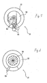
- Fig. 6 shows a diaphragm mechanism 31 used in the third embodiment.
- a plurality of vanes 54 are superimposed upon each other, one end of each vane 54 slidably engaging an inner peripheral groove that is formed along the inner periphery of the middle cylindrical section 22, and an iris diaphragm is formed as a numerical aperture changer.
- the numerical aperture can be successively changed. According to such a structure, since the numerical aperture can be successively changed, it can be adjusted to an optimal numerical aperture according to the type of object to be observed and type of application.
- the telecentric lens system 3 and the image measuring device 1 of the present invention are not limited to those of the above-described embodiments, so that, obviously, various modifications may be made within a scope not departing from the gist of the present invention.
- a drive source such as a motor, may be provided at the numerical aperture changer in order to change the numerical aperture by the drive source.
- the driving operation of the drive source may be controlled by, for example, a computer.
- the diaphragm mechanisms 31 are not limited to those of the above-described embodiments. Any diaphragm mechanism 31 may be used as long as it can change the numerical aperture.
- the telecentric lens system and the image measuring device of the present invention provide excellent advantages such as the capability of adjusting the focal depth and resolution and the capability of being used in a wide range of observational applications.
Landscapes
- Physics & Mathematics (AREA)
- General Physics & Mathematics (AREA)
- Optics & Photonics (AREA)
- Lenses (AREA)
- Microscoopes, Condenser (AREA)
- Lens Barrels (AREA)
- Diaphragms For Cameras (AREA)
Abstract
Description
Claims (7)
- A telecentric lens system comprising:a front lens unit;a rear lens unit which is disposed so that the front focal point of the rear lens unit coincides with the back focal point of the front lens unit; anda diaphragm mechanism which is disposed at the location where the back focal point of the front lens unit and the front focal point of the rear lens unit coincide, the diaphragm mechanism comprising a numerical aperture changer for changing the numerical aperture of the diaphragm mechanism.
- A telecentric lens system according to Claim 1, wherein the numerical aperture changer has at least two diaphragms having numerical apertures that differ successively, and wherein, by changing one diaphragm with another diaphragm, the numerical aperture is changed.
- A telecentric lens system according to Claim 2, wherein the diaphragms are successively provided in one plate, and wherein, by moving the plate, the numerical aperture is changed.
- A telecentric lens system according to Claim 2, wherein the diaphragms are provided in swingably supported levers, respectively, and wherein, by movement of any one of the levers, the numerical aperture is changed.
- A telecentric lens system according to Claim 1, wherein the numerical aperture changer comprises an iris diaphragm for successively changing the numerical aperture.
- A telecentric lens system according to any one of Claims 1 to 5, wherein either the front lens unit or the rear lens unit is changeable.
- An image measuring device comprising:the telecentric lens system of any one of Claims 1 to 6; andan imaging optical system that is connected to the telecentric lens system.
Applications Claiming Priority (2)
| Application Number | Priority Date | Filing Date | Title |
|---|---|---|---|
| JP2002035922A JP4157305B2 (en) | 2002-02-13 | 2002-02-13 | Telecentric lens system and image measuring device |
| JP2002035922 | 2002-02-13 |
Publications (2)
| Publication Number | Publication Date |
|---|---|
| EP1336886A2 true EP1336886A2 (en) | 2003-08-20 |
| EP1336886A3 EP1336886A3 (en) | 2004-06-23 |
Family
ID=27621410
Family Applications (1)
| Application Number | Title | Priority Date | Filing Date |
|---|---|---|---|
| EP03000585A Withdrawn EP1336886A3 (en) | 2002-02-13 | 2003-01-13 | Telecentric system and image measuring device |
Country Status (3)
| Country | Link |
|---|---|
| US (1) | US6707617B2 (en) |
| EP (1) | EP1336886A3 (en) |
| JP (1) | JP4157305B2 (en) |
Cited By (3)
| Publication number | Priority date | Publication date | Assignee | Title |
|---|---|---|---|---|
| WO2008138687A1 (en) * | 2007-05-11 | 2008-11-20 | Robert Bosch Gmbh | Optics for image processing and method for reducing aberrations in said optics |
| EP2093597A1 (en) * | 2008-02-21 | 2009-08-26 | Mitutoyo Corporation | Telecentric lens system and vision measuring instrument |
| CN103995337A (en) * | 2014-06-12 | 2014-08-20 | 苏州科德溯源仪器有限公司 | Long-focus telecentric lens of image measurement instrument |
Families Citing this family (16)
| Publication number | Priority date | Publication date | Assignee | Title |
|---|---|---|---|---|
| JP5439218B2 (en) * | 2010-02-17 | 2014-03-12 | 株式会社ミツトヨ | Image measuring machine |
| KR101186464B1 (en) * | 2011-04-13 | 2012-09-27 | 에스엔유 프리시젼 주식회사 | Interferometric system for measuring tsv and method using the same |
| US10088431B2 (en) | 2011-05-17 | 2018-10-02 | Gii Acquisition, Llc | Method and system for optically inspecting headed manufactured parts |
| US9697596B2 (en) | 2011-05-17 | 2017-07-04 | Gii Acquisition, Llc | Method and system for optically inspecting parts |
| US10094785B2 (en) | 2011-05-17 | 2018-10-09 | Gii Acquisition, Llc | Method and system for optically inspecting headed manufactured parts |
| CN102955228B (en) * | 2011-08-22 | 2014-12-17 | 上海微电子装备有限公司 | Machine vision imaging lens structure |
| ITBS20130179A1 (en) * | 2013-11-29 | 2015-05-30 | Claudio Sedazzari | APPARATUS FOR ARTIFICIAL VISION |
| JP6344977B2 (en) * | 2014-05-28 | 2018-06-20 | 株式会社ミツトヨ | Optical system and image measuring apparatus |
| CN104360463B (en) * | 2014-12-05 | 2016-08-24 | 桂林电子科技大学 | Three telecentricity coaxial-illuminating imaging optical systems |
| JP6685849B2 (en) | 2016-06-17 | 2020-04-22 | 株式会社ミツトヨ | Optical interference measuring device and optical interference measuring method |
| CN106483642B (en) * | 2016-12-14 | 2023-05-09 | 舜宇光学(中山)有限公司 | Double telecentric lens based on machine vision |
| CN110646929B (en) * | 2019-09-30 | 2025-06-13 | 陕西维视数字图像技术有限公司 | A double-magnification telecentric lens with a large field of view |
| CN110989137B (en) * | 2019-12-20 | 2022-03-11 | 东莞市普密斯精密仪器有限公司 | Double-telecentric lens |
| CN113655600A (en) * | 2021-08-18 | 2021-11-16 | 桂林量具刃具有限责任公司 | A double magnification bi-telecentric lens |
| WO2025041200A1 (en) * | 2023-08-18 | 2025-02-27 | 株式会社ニコン | Imaging device and imaging system |
| CN120044680B (en) * | 2025-03-24 | 2025-11-04 | 广东奥普特科技股份有限公司 | High-precision measuring lens and optical system thereof |
Family Cites Families (8)
| Publication number | Priority date | Publication date | Assignee | Title |
|---|---|---|---|---|
| US5625495A (en) * | 1994-12-07 | 1997-04-29 | U.S. Precision Lens Inc. | Telecentric lens systems for forming an image of an object composed of pixels |
| JP3386269B2 (en) * | 1995-01-25 | 2003-03-17 | 株式会社ニュークリエイション | Optical inspection equipment |
| EP0747743B1 (en) * | 1995-06-03 | 1997-08-27 | Jos. Schneider Optische Werke Kreuznach GmbH & Co. KG | Measurement objective telecentric on both sides |
| US5668665A (en) * | 1995-07-10 | 1997-09-16 | Optical Gaging Products, Inc. | Telecentric, parfocal, multiple magnification optical system for videoinspection apparatus |
| US6027261A (en) * | 1997-03-31 | 2000-02-22 | Nisca Corporation | Exposure adjusting device for a camera |
| JPH11214293A (en) * | 1998-01-22 | 1999-08-06 | Nikon Corp | Projection optical system, exposure apparatus having the optical system, and device manufacturing method |
| US6198577B1 (en) * | 1998-03-10 | 2001-03-06 | Glaxo Wellcome, Inc. | Doubly telecentric lens and imaging system for multiwell plates |
| JP2002090654A (en) * | 2000-09-12 | 2002-03-27 | Olympus Optical Co Ltd | Intermediate lens barrel having projection optical system, and microscope having projection optical system |
-
2002
- 2002-02-13 JP JP2002035922A patent/JP4157305B2/en not_active Expired - Fee Related
-
2003
- 2003-01-13 EP EP03000585A patent/EP1336886A3/en not_active Withdrawn
- 2003-01-30 US US10/354,678 patent/US6707617B2/en not_active Expired - Lifetime
Cited By (4)
| Publication number | Priority date | Publication date | Assignee | Title |
|---|---|---|---|---|
| WO2008138687A1 (en) * | 2007-05-11 | 2008-11-20 | Robert Bosch Gmbh | Optics for image processing and method for reducing aberrations in said optics |
| EP2093597A1 (en) * | 2008-02-21 | 2009-08-26 | Mitutoyo Corporation | Telecentric lens system and vision measuring instrument |
| US7959291B2 (en) | 2008-02-21 | 2011-06-14 | Mitutoyo Corporation | Telecentric lens system and vision measuring instrument |
| CN103995337A (en) * | 2014-06-12 | 2014-08-20 | 苏州科德溯源仪器有限公司 | Long-focus telecentric lens of image measurement instrument |
Also Published As
| Publication number | Publication date |
|---|---|
| JP2003232999A (en) | 2003-08-22 |
| US20030151823A1 (en) | 2003-08-14 |
| US6707617B2 (en) | 2004-03-16 |
| EP1336886A3 (en) | 2004-06-23 |
| JP4157305B2 (en) | 2008-10-01 |
Similar Documents
| Publication | Publication Date | Title |
|---|---|---|
| US6707617B2 (en) | Telecentric lens system and image measuring device | |
| EP2093597B1 (en) | Telecentric lens system and vision measuring instrument | |
| US6292306B1 (en) | Telecentric zoom lens system for video based inspection system | |
| CN1188674C (en) | Wavefront sensor and lens detector and active reflective optic telescope with it | |
| US9429740B2 (en) | Telecentric modular zoom system | |
| US4634240A (en) | Optical apparatus using polarized light | |
| JPH11351871A (en) | Focus adjustment lens position detector | |
| CN111366088B (en) | Laser confocal height measuring method | |
| KR101375196B1 (en) | Microscope | |
| CN114303086A (en) | Apparatus and method for imaging an object | |
| JP3782303B2 (en) | Epi-illumination microscope | |
| EP3951467B1 (en) | Scanning microscope unit | |
| US7330317B2 (en) | Lens system and image capturing apparatus | |
| EP2103981A1 (en) | Optical unit and measuring instrument with plural afocal optical systems for changing magnification | |
| JPH0593845A (en) | Automatic focus detecting device | |
| JP2005274837A (en) | Eccentricity adjustment method of zoom lens | |
| JP4792163B2 (en) | Microscope equipment | |
| US5289226A (en) | Focus detecting device including a diffusion surface disposed on a predetermined image surface | |
| Bloch et al. | Telecentric zoom lens used in metrology applications | |
| US12517005B2 (en) | Apparatus and method for measuring an optical property of an optical system | |
| JP2946839B2 (en) | Variable illumination optical system | |
| JP2004139065A (en) | Variable power binoculars | |
| JPH07253547A (en) | Illumination device for microscope | |
| US20060012861A1 (en) | Ergotube and inverted microscope having an ergotube | |
| JPH06214166A (en) | Epi-illumination microscope |
Legal Events
| Date | Code | Title | Description |
|---|---|---|---|
| PUAI | Public reference made under article 153(3) epc to a published international application that has entered the european phase |
Free format text: ORIGINAL CODE: 0009012 |
|
| AK | Designated contracting states |
Designated state(s): AT BE BG CH CY CZ DE DK EE ES FI FR GB GR HU IE IT LI LU MC NL PT SE SI SK TR |
|
| AX | Request for extension of the european patent |
Extension state: AL LT LV MK RO |
|
| PUAL | Search report despatched |
Free format text: ORIGINAL CODE: 0009013 |
|
| AK | Designated contracting states |
Kind code of ref document: A3 Designated state(s): AT BE BG CH CY CZ DE DK EE ES FI FR GB GR HU IE IT LI LU MC NL PT SE SI SK TR |
|
| AX | Request for extension of the european patent |
Extension state: AL LT LV MK RO |
|
| RIC1 | Information provided on ipc code assigned before grant |
Ipc: 7G 02B 5/00 B Ipc: 7G 02B 26/02 B Ipc: 7G 02B 13/22 A |
|
| 17P | Request for examination filed |
Effective date: 20040604 |
|
| 17Q | First examination report despatched |
Effective date: 20040804 |
|
| AKX | Designation fees paid |
Designated state(s): DE FR GB IT |
|
| RBV | Designated contracting states (corrected) |
Designated state(s): DE FR GB IT |
|
| STAA | Information on the status of an ep patent application or granted ep patent |
Free format text: STATUS: THE APPLICATION IS DEEMED TO BE WITHDRAWN |
|
| 18D | Application deemed to be withdrawn |
Effective date: 20060425 |