EP1336687B1 - Surface calender and a method for surface calendering - Google Patents
Surface calender and a method for surface calendering Download PDFInfo
- Publication number
- EP1336687B1 EP1336687B1 EP03002421A EP03002421A EP1336687B1 EP 1336687 B1 EP1336687 B1 EP 1336687B1 EP 03002421 A EP03002421 A EP 03002421A EP 03002421 A EP03002421 A EP 03002421A EP 1336687 B1 EP1336687 B1 EP 1336687B1
- Authority
- EP
- European Patent Office
- Prior art keywords
- roll
- carrier
- contact
- nip
- webs
- Prior art date
- Legal status (The legal status is an assumption and is not a legal conclusion. Google has not performed a legal analysis and makes no representation as to the accuracy of the status listed.)
- Expired - Lifetime
Links
- 238000000034 method Methods 0.000 title claims abstract description 37
- 238000003490 calendering Methods 0.000 title abstract description 46
- 239000000463 material Substances 0.000 claims description 42
- 238000010030 laminating Methods 0.000 claims description 35
- 238000003475 lamination Methods 0.000 claims description 26
- 238000000576 coating method Methods 0.000 claims description 25
- 239000011248 coating agent Substances 0.000 claims description 24
- 239000012530 fluid Substances 0.000 claims description 21
- 239000012876 carrier material Substances 0.000 claims description 8
- 239000012943 hotmelt Substances 0.000 claims description 8
- 239000000853 adhesive Substances 0.000 claims description 6
- -1 fleece Substances 0.000 claims description 4
- 239000004745 nonwoven fabric Substances 0.000 claims description 3
- 238000005516 engineering process Methods 0.000 claims description 2
- 239000006260 foam Substances 0.000 claims description 2
- 238000005507 spraying Methods 0.000 claims description 2
- 238000005253 cladding Methods 0.000 claims 4
- 238000001266 bandaging Methods 0.000 claims 2
- 230000003750 conditioning effect Effects 0.000 claims 2
- 239000010408 film Substances 0.000 claims 2
- 239000002759 woven fabric Substances 0.000 claims 2
- 230000008569 process Effects 0.000 description 23
- 230000035515 penetration Effects 0.000 description 9
- 238000005496 tempering Methods 0.000 description 8
- 239000000123 paper Substances 0.000 description 6
- 239000004744 fabric Substances 0.000 description 5
- 230000000694 effects Effects 0.000 description 4
- 239000000969 carrier Substances 0.000 description 3
- 239000002131 composite material Substances 0.000 description 3
- 239000000758 substrate Substances 0.000 description 3
- 230000009471 action Effects 0.000 description 2
- 238000004873 anchoring Methods 0.000 description 2
- 238000005266 casting Methods 0.000 description 2
- 238000003754 machining Methods 0.000 description 2
- 238000004519 manufacturing process Methods 0.000 description 2
- 229910052751 metal Inorganic materials 0.000 description 2
- 239000002184 metal Substances 0.000 description 2
- 239000000203 mixture Substances 0.000 description 2
- 238000003825 pressing Methods 0.000 description 2
- 238000005096 rolling process Methods 0.000 description 2
- 239000002390 adhesive tape Substances 0.000 description 1
- 229910052782 aluminium Inorganic materials 0.000 description 1
- XAGFODPZIPBFFR-UHFFFAOYSA-N aluminium Chemical compound [Al] XAGFODPZIPBFFR-UHFFFAOYSA-N 0.000 description 1
- 238000000418 atomic force spectrum Methods 0.000 description 1
- 230000009286 beneficial effect Effects 0.000 description 1
- 238000007664 blowing Methods 0.000 description 1
- 230000008859 change Effects 0.000 description 1
- 238000003776 cleavage reaction Methods 0.000 description 1
- 239000000470 constituent Substances 0.000 description 1
- 230000001419 dependent effect Effects 0.000 description 1
- 238000005485 electric heating Methods 0.000 description 1
- 230000009969 flowable effect Effects 0.000 description 1
- 238000010438 heat treatment Methods 0.000 description 1
- 239000002655 kraft paper Substances 0.000 description 1
- 238000007639 printing Methods 0.000 description 1
- 238000003672 processing method Methods 0.000 description 1
- 230000007017 scission Effects 0.000 description 1
- 239000007921 spray Substances 0.000 description 1
- 238000003892 spreading Methods 0.000 description 1
- 230000007480 spreading Effects 0.000 description 1
- 239000000126 substance Substances 0.000 description 1
- 239000004753 textile Substances 0.000 description 1
- 229920001187 thermosetting polymer Polymers 0.000 description 1
- XLYOFNOQVPJJNP-UHFFFAOYSA-N water Chemical compound O XLYOFNOQVPJJNP-UHFFFAOYSA-N 0.000 description 1
Images


Classifications
-
- B—PERFORMING OPERATIONS; TRANSPORTING
- B32—LAYERED PRODUCTS
- B32B—LAYERED PRODUCTS, i.e. PRODUCTS BUILT-UP OF STRATA OF FLAT OR NON-FLAT, e.g. CELLULAR OR HONEYCOMB, FORM
- B32B37/00—Methods or apparatus for laminating, e.g. by curing or by ultrasonic bonding
- B32B37/14—Methods or apparatus for laminating, e.g. by curing or by ultrasonic bonding characterised by the properties of the layers
- B32B37/16—Methods or apparatus for laminating, e.g. by curing or by ultrasonic bonding characterised by the properties of the layers with all layers existing as coherent layers before laminating
- B32B37/20—Methods or apparatus for laminating, e.g. by curing or by ultrasonic bonding characterised by the properties of the layers with all layers existing as coherent layers before laminating involving the assembly of continuous webs only
-
- B—PERFORMING OPERATIONS; TRANSPORTING
- B32—LAYERED PRODUCTS
- B32B—LAYERED PRODUCTS, i.e. PRODUCTS BUILT-UP OF STRATA OF FLAT OR NON-FLAT, e.g. CELLULAR OR HONEYCOMB, FORM
- B32B37/00—Methods or apparatus for laminating, e.g. by curing or by ultrasonic bonding
- B32B37/0046—Methods or apparatus for laminating, e.g. by curing or by ultrasonic bonding characterised by constructional aspects of the apparatus
- B32B37/0053—Constructional details of laminating machines comprising rollers; Constructional features of the rollers
-
- B—PERFORMING OPERATIONS; TRANSPORTING
- B32—LAYERED PRODUCTS
- B32B—LAYERED PRODUCTS, i.e. PRODUCTS BUILT-UP OF STRATA OF FLAT OR NON-FLAT, e.g. CELLULAR OR HONEYCOMB, FORM
- B32B2309/00—Parameters for the laminating or treatment process; Apparatus details
- B32B2309/06—Angles
-
- B—PERFORMING OPERATIONS; TRANSPORTING
- B32—LAYERED PRODUCTS
- B32B—LAYERED PRODUCTS, i.e. PRODUCTS BUILT-UP OF STRATA OF FLAT OR NON-FLAT, e.g. CELLULAR OR HONEYCOMB, FORM
- B32B2309/00—Parameters for the laminating or treatment process; Apparatus details
- B32B2309/16—Tension
Definitions
- the invention encompasses a surface calender and method for laminating or laminating support materials such as, for example, fabric, fleece or films, in particular for the production of dressings which are coated with hot-melt self-adhesive compositions.
- Calendering is a pressing and rolling treatment of support materials, such as paper, rubber or films, for finishing or finishing aftertreatment of fabrics, knitted fabrics, fleece or films.
- a calender can also be used for laminating or laminating materials. Between two rolls, a web-shaped material is introduced or several materials are brought together and treated or processed between the rolls. The web-shaped materials (carrier) can also be coated with other materials.
- a distinction is made between calendering, laminating, laminating and coating of carrier materials.
- Laminating is understood to mean the bonding of two support materials under the action of low to medium pressure. There is a hang up, covering the materials.
- Lamination is understood to mean the bonding of two carrier materials under the effect of generally higher pressure.
- Coating means the application / application of fluids, pastes and / or webs to a support in the form of spreading, casting, spraying, rolling, pressing or the like.
- laminating or laminating a basically identical technique can be used, so that is spoken by the calender, laminating or laminating.
- laminating or laminating which also includes the present invention, two substrates, one or both of which may be fluid coated, are laminated.
- Calendering is usually done by line contact between the rolls.
- Known simple calendering or laminating basically consist of two rolls.
- calendering also called calendering
- the product is passed in a defined path between the calender rolls.
- the gap or force between the roller pair tempering of the rollers, preheating of the laminate components or variation of the roller drive speeds, the calendering result is individually influenced. This leads u.a. on certain thickness, density or transparency values or surface effects of the calendered product.
- Figures 1 and 2 illustrate the principle of the two-roll calender ( illustration 1 ) and the multiple calender ( Figure 2 ) as known in the art.
- illustration 1 outlines a two-roll calender, with the two supports being passed between two rolls.
- Figure 2 shows a Mehrfachwalzenkalander, wherein the carriers are carried out by guide rollers one behind the other between two rollers.
- Figures 3, 4 and 5 The coating processes conventionally used in the paper, printing and textile industries in conjunction with calenders and calendering processes are outlined in Figures 3, 4 and 5.
- the illustrated calenders and calendering processes find application in the prior art even without a preceding coating. It is essential that all known devices and methods based on the principle of "line contact”. So shows Figure 3 a lamination / lamination process via engraving, screen or smooth roll against a calender roll.
- Figure 4 shows a lamination / lamination process via a coating roll against a calender roll.
- Figure 5 shows a lamination / lamination process via a roll applicator against a calender roll.
- DE 19547164 C1 describes a calender for the treatment of a paper web.
- the calender consists of several rolls, a top roll, a plurality of intermediate rolls and an end roll, which are arranged as a roll stack.
- deflection rollers By deflection rollers, the paper web passes through the respective nip of two rolls.
- the illustrated embodiments always give a line contact as a treatment zone between the rollers.
- the surface quality of the paper web can be determined by the roughness of the paper Roll surface, the temperature, the compressive stress in the nip and the gap width vary.
- WO 01/68019 A1 discloses an assembly for making stretchable closures.
- the stretchable material web is guided around a temperature-controlled roller and laminated in the nip with a second roller. Lamination over the circumference of the temperature-controlled roll does not take place.
- GB 2006109 describes the lamination of metal, primarily aluminum, by means of a calender, wherein also here the lamination between two rolls is in line contact.
- the pamphlets DE 10005306 C1 . DE 19945780 C1 . DE 10010772 C1 . DE 19820087 A1 and DE 19631056 A1 disclose calender arrangements in which the carrier webs to be laminated or also to be coated are processed by a line contact of two calender rolls.
- the machining parameters are, inter alia, always the nip and the roller pressure within the line contact gap.
- the profile adjustment on the calendering line gap is traditionally carried out by locally changing the diameter of the metal roll or the nip pressure and / or by using so-called deflection-adjustable rolls, by means of which the nip force profile can be set in the desired manner , which in turn leads to changes in the surface properties of the calendered carrier.
- the invention comprises a calendering process for surface laminating, laminating carrier webs.
- the calender according to the invention thus consists in the simplest embodiment ( Figure 6 ) of three rolls and two carrier webs or materials to be calendered.
- the carrier webs (4, 5) are guided via the feed roller (1) through the nip (6) between the feed roller (1) and the contact roller (3).
- the carrier webs are now guided around the contact roller (3) through the nip (7) between the contact roller (3) and the discharge roller (2). They enclose the contact roller (3) in a certain circular segment (8), which is determined by the positioning of the rollers (1, 2, 3) to each other.
- the circular segment spans an angular range of the contact roller of> 180 °.
- the carrier webs thus experience in the first gap (6) and second gap (7) a Walzentinientitle and additionally on the spanned circular segment (8) (cylindrical surface segment) of the contact roller (3) a flat roller contact.
- the carrier webs are line-calendered / laminated between the rolls (1) and (3) and (2) and (3) and additionally surface calendered / laminated over the wrap-around sheet (8) of the contact roll.
- the finished product (12) can then be further processed.
- Figure 6, 7 and 8th illustrates the arrangement possibilities of the rollers (1, 2, 3) in order to produce different wrap segments, angular regions (8) of the contact roller surface looped with the carrier webs (4, 5). Circle segments with an angle range between 5 ° and 355 °, depending on the roll diameter, can be set. Preferred are contact surfaces, ie angle ranges between 90 ° and 270 °, in particular angle ranges over 180 ° and particularly preferred is an angle of 210 °.
- the gap between the feed roller (1) and the contact roller (3) and / or the gap between the Abzhouwalze (2) and the contact roller (3) can be varied as desired via the roller arrangement, so that in extreme cases no line contact in the nip (6) and / or (7).
- Figure 9 outlined this embodiment of the surface calender according to the invention by in the gap (6) no line contact and in the gap (7) line contact is made.
- the other influencing factors in the calender according to the invention are identical to those of a conventional calendering unit. That Cleavage or nip pressure setting, pre-tempering of the laminate components, roll surface etc.
- An additional decisive influencing factor in the calender according to the invention but caused by the web guide around the contact roller (3) in the laminate perpendicular to the web tension / tensile forces acting on the radial forces on the roller (3 ), which are determined in size by the web tension / tension in the laminate.
- the web tension produced in the carrier webs does not ensure, as in the conventional calenders and calendering processes, only the degree of stretching of the laminate during lamination and a wrinkle-free lamination, but also determines the surface pressure at the circle segment (8) during the lamination process.
- the tensile stress in the laminate produced at the contact roller (3) radial forces acting in the laminate perpendicular to the tensile forces and not linear but flat on the laminate. This creates a surface pressure as a function of the web tension and the cylindrical surface segment (8). Depending on the web speed, a casting time of calendering is created.
- the radial forces additionally generated by the web tension in the contact area determine the laminating, lamination process, which is only influenced by the forces (pressure, gap size) between two rolls during line contact. In line contact, the web tension can not generate radial forces.
- the penetration depth (penetration) of a fluid-coated open carrier such as paving materials, non-wovens, etc., control more secure. An undesired complete penetration of the fluid through the carrier can thus be avoided.
- the anchoring and the composite of the curing fluid with one or more carriers can be significantly influenced.
- the lamination, lamination is effected by the surface contact and thus produces a longer contact time of the materials to be treated, carrier webs.
- the tensile stress in the carrier, laminate is a factor of influence additionally generated by this technique for lamination, lamination.
- the tension creates radial forces to the contact roller which act throughout the laminating, laminating process.
- Open backings, such as paving or fabric materials, can thus be laminated more gently, laminated, and adhesive tape penetrations, such as those that can occur, in particular, during the production of patches, are avoided.
- the surface calender takes place a lower force or pressure on the wearer over a longer contact period.
- stretchable carrier materials stretching of the material by surface calendering is also possible.
- the desired stretching end state can be better stabilized, ie frozen, by the calender arrangement according to the invention.
- the surface contact also allows a better temperature control of the laminate over the rollers.
- tempering during the laminating process the desired state can be additionally stabilized before the laminate is released again.
- the tempering during lamination is thus a further additional influencing factor in comparison with the conventional line calenders and calendering methods.
- the tempering before, during and after laminating can also be carried out with common devices, IR heating, hot air blowing, various electric heating elements.
- the tempering devices for tempering can be attached to and / or in the contact roller (3).
- the calendering unit may additionally be equipped with deflecting rollers (11), as known from the known calenders of the prior art, as disclosed in US Pat Figure 10 is clarified.
- a calendering unit can consist of several surface calenders according to the invention and / or known line calenders.
- the feed (1) and / or removal rollers (2) may further be equipped with compensation cylinders, with / without piston lifting devices, so that a Spaltkraft- and / or gap size adjustment is possible, as for example DE 10010772 C1 is known.
- the possibility of variation of the influencing variables is purposefully increased by the calender according to the invention. It is possible to combine two line and one area contact calenders, one line and one area contact calender and / or only one area contact calender, thus generating individual calendering methods with specific processing parameters.
- thermosetting fluid as a laminate component, such as a hotmelt PSA
- the coating, surface laminating also on the fluid coating roll (3), as in Figure 11 is clarified.
- the carrier webs (4, 5) are guided via the feed roller (1) to the contact roller (3), here also the coating roller.
- the coating material for example hot melt fluid
- the application of the fluid can be carried out by a coating head, for example a nozzle, or else from a fluid bath, via a roller applicator and by spray technology (10).
- the coating and lamination takes place via the contact surface (8) of the contact roller (3) before the laminated product is removed via the discharge roller (2).
- the carrier is applied to the contact roller during coating. There is a coating against the contact roller (3). If the carrier is coated off roll, the coating head is adjusted below the center of the roll, so that there is a greater distance between the coating head and the contact roller and the coating material has alternative possibilities.
- the surface calender according to the invention and the calendering process ultimately also enables higher process speeds as a result of the illustrated combination possibilities and processing methods, and it is possible to greatly reduce the described advantages in terms of process energy and plant investment costs.
- the surface calender can be used for a wide variety of laminating processes / laminates.
- the laminate components can be web-shaped, network-shaped Carrier webs and / or be coated with reactive, thermal or pressure-curing fluids or coated.
- the fluids on a web-shaped structure can be applied over the entire surface or partially.
- a permanent deformation of the application by the surface calender can be achieved due to the tempering and exposure time, which is not possible with a line calendering unit.
- the carrier materials may be open carriers, fleece, fabrics, foams or so-called non-wovens.
- the materials must be tolerated by the skin, usually permeable to air and / or water vapor, as well as easy to model and to conform to.
- the surface calender according to the invention the user can set the desired machining properties specifically.
Abstract
Description
Die Erfindung umfasst ein Flächenkalander und -verfahren zur flächigen Laminierung oder Kaschierung von Trägermaterialien wie beispielsweise Gewebe, Vlies oder Folien, insbesondere zur Herstellung von Verbandstoffen, die mit hotmelt-Selbstklebemassen beschichtet sind.The invention encompasses a surface calender and method for laminating or laminating support materials such as, for example, fabric, fleece or films, in particular for the production of dressings which are coated with hot-melt self-adhesive compositions.
Das Kalandern ist eine pressende und walzende Bearbeitung von Trägermaterialien, wie beispielsweise Papier, Kautschuk oder Folien, zur Appretur oder Appretur-Nachbehandlung von Gewebe, Gewirke, Vlies oder Folien. Ein Kalander ist zudem einsetzbar zum Kaschieren oder Laminieren von Materialien. Zwischen zwei Walzen wird ein bahnförmiges Material eingeführt oder es werden mehrere Materialien zusammengeführt und zwischen den Walzen behandelt bzw. bearbeitet. Die bahnförmigen Materialien (Träger) können zudem mit weiteren Materialien beschichtet sein.
Man unterscheidet zwischen dem Kalandern, Laminieren, Kaschieren und Beschichten von Trägermaterialien. Unter Kaschieren wird das Verbinden zweier Trägermaterialien unter Einwirkung geringen bis mittleren Drucks verstanden. Es erfolgt ein Auflegen, Abdecken der Materialien. Unter Laminieren wird das Verbinden zweier Trägermaterialien unter Einwirkung meist höheren Drucks verstanden. Beim Kalandern sind meist hohe Kräfte/Drücke erforderlich um die Eigenschaften des Materials durch mechanisch Einwirkung zu verändern. Beschichten bedeutet das Auftragen/Auflegen von Fluiden, Pasten und/oder Materialbahnen auf einen Träger in Form von Ausstreichen, Gießen, Aufsprühen, Aufwalzen, Auspressen oder dergleichen.
Für das Kalandern, Kaschieren oder Laminieren kann eine im Prinzip identische Technik verwendet werden, so dass gleichbedeutend vom Kalander, Kaschierwerk oder Laminierwerk gesprochen wird. Beim Kalandern, Laminieren oder Kaschieren, zu dem auch die vorliegende Erfindung zählt, werden zwei Trägermaterialen, von denen eins oder beide mit Fluiden beschichtet sein können, laminiert bzw. kaschiert.Calendering is a pressing and rolling treatment of support materials, such as paper, rubber or films, for finishing or finishing aftertreatment of fabrics, knitted fabrics, fleece or films. A calender can also be used for laminating or laminating materials. Between two rolls, a web-shaped material is introduced or several materials are brought together and treated or processed between the rolls. The web-shaped materials (carrier) can also be coated with other materials.
A distinction is made between calendering, laminating, laminating and coating of carrier materials. Laminating is understood to mean the bonding of two support materials under the action of low to medium pressure. There is a hang up, covering the materials. Lamination is understood to mean the bonding of two carrier materials under the effect of generally higher pressure. When calendering usually high forces / pressures are required to change the properties of the material by mechanical action. Coating means the application / application of fluids, pastes and / or webs to a support in the form of spreading, casting, spraying, rolling, pressing or the like.
For calendering, laminating or laminating a basically identical technique can be used, so that is spoken by the calender, laminating or laminating. In calendering, laminating or laminating, which also includes the present invention, two substrates, one or both of which may be fluid coated, are laminated.
Das Kalandern erfolgt üblicherweise durch einen Linienkontakt zwischen den Walzen. Bekannte einfache Kalander- oder Laminierwerke bestehen im Grunde aus zwei Walzen.Calendering is usually done by line contact between the rolls. Known simple calendering or laminating basically consist of two rolls.
Durch die Anordnung mehrerer Walzen entstehen zwar Mehrfachkalander, wobei jedoch nur eine linienförmige Berührung zwischen zwei Walzen gegeben ist. Beim Bearbeitungsprozeß durch Kalandern, auch Kalandrieren genannt, wird die Ware in definierter Bahn zwischen den Kalanderwalzen hindurchgeführt. Durch Spalt- oder Krafteinstellung zwischen dem Walzenpaar, Temperierung der Walzen, Vorwärmung der Laminatbestandteile oder Variation der Walzenantriebsgeschwindigkeiten wird das Kalanderergebnis individuell beeinflusst. Dies führt u.a. zu bestimmten Dicken-, Dichteoder Transparenzwerten oder Oberflächeneffekten der kalandrierten Ware.Although the arrangement of several rolls produces multiple calenders, only a linear contact between two rolls is provided. In the processing process by calendering, also called calendering, the product is passed in a defined path between the calender rolls. By adjusting the gap or force between the roller pair, tempering of the rollers, preheating of the laminate components or variation of the roller drive speeds, the calendering result is individually influenced. This leads u.a. on certain thickness, density or transparency values or surface effects of the calendered product.
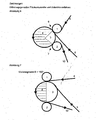
Die Abbildungen 1 und 2 veranschaulichen das Prinzip des Zweiwalzenkalander (
Die in der Papier-, Druck- und Textilindustrie herkömmlich verwendeten Beschichtungsverfahren in Verbindung mit Kalander und Kalandrierverfahren sind in den Abbildungen 3, 4 und 5 skizziert. Die dargestellten Kalander und Kalandrierverfahren finden auch ohne eine vorangehende Beschichtung Anwendung im Stand der Technik. Wesentlich ist, dass alle bekannten Vorrichtungen und Verfahren auf dem Prinzip des "Linien-Kontaktes" basieren. So zeigt
Auch die Druckschriften
- ein flächiger Kontakt der Trägerbahnen mit der Walze (16) resultiert (D1
Fig. 1 ) und - die Trägerbahnen durch einen Spalt (20), gebildet zwischen der Trägerbahnzuführwalze (14) und der Kontaktwalze (16), um die Kontaktwalze herum durch den Spalt (22), gebildet zwischen der Kontaktwalze und der Abführwalze (18), geführt werden.
- a flat contact of the carrier webs with the roller (16) results (D1
Fig. 1 ) and - the carrier webs are passed through a nip (20) formed between the carrier web feed roller (14) and the contact roller (16) around the contact roller through the nip (22) formed between the contact roller and the discharge roller (18).
Um Einfluss auf die Eigenschaften der kalandrierten Trägermaterialien zu gewinnen, wird traditionell die am Kalanderlinienspalt erfolgende Profileinstellung durch lokales Ändern des Durchmessers der Metallwalze oder des Spaltdruckes und/oder durch den Einsatz sog. durchbiegungseinstellbaren Walzen durchgeführt, mittels welcher sich das Spaltkraftprofil auf gewünschte Weise einstellen lässt, was wiederum zu Änderungen der Oberflächeneigenschaften des kalandrierten Trägers führt.To gain influence on the properties of the calendered support materials, the profile adjustment on the calendering line gap is traditionally carried out by locally changing the diameter of the metal roll or the nip pressure and / or by using so-called deflection-adjustable rolls, by means of which the nip force profile can be set in the desired manner , which in turn leads to changes in the surface properties of the calendered carrier.
Bekannt ist ebenfalls das vollflächige oder partielle Auftragen von Beschichtungsstoffen, wie z.B. Fluide, insbesondere hotmelt-Selbstklebemassen, auf Trägermaterialien durch Zweiwalzen- oder Mehrfachwalzenkalander. Bei der partiellen Auftragung von Beschichtungsstoffen ist jedoch eine dauerhafte Verformung des partiell aufgetragenen Stoffes durch den Linienkontakt beim üblichen Kalandrieren nicht möglich.Also known is the full-surface or partial application of coating materials, such. Fluids, in particular hot melt self-adhesive compositions, on support materials by two-roll or Mehrwalwalzenkalander. In the partial application of coating materials, however, a permanent deformation of the partially applied substance by the line contact in the usual calendering is not possible.
Bei allen bekannten Kalandrierverfahren besteht zwischen den Trägermaterialien und Beschichtungsstoffen zwischen zwei Walzen nur ein Linienkontakt. Nachteilig an dieser Verfahrensweise ist die relativ kurze Kontaktzeit zwischen Träger und dem Auftragmedium, das eine zweite Trägerbahn (Laminieren) und/oder ein Fluid (Beschichten) sein kann. Bei einem offenen Träger, wie z.B. Gewebe oder Flies, besteht dabei nachteilig die Möglichkeit entweder keinen ausreichenden Verbund der Materialien zu erzeugen oder eine vollständige Penetration des Fluids durch den Träger zu erhalten. Beides ist unerwüscht. Weiterhin nachteilig bei den bekannten Kalandern mit Linienkontakt ist der geringe Einfluss der Walzen auf die Temperatur im Laminat während des Laminier-, Kaschierprozesses.In all known calendering between the substrates and coating materials between two rolls only a line contact. A disadvantage of this procedure is the relatively short contact time between the carrier and the application medium, which may be a second carrier web (lamination) and / or a fluid (coating). In an open carrier, such as tissue or fleece, there is the disadvantage of either the possibility either not to produce sufficient composite of the materials or to obtain a complete penetration of the fluid by the carrier. Both are undesirable. Another disadvantage of the known calenders with line contact is the low influence of the rolls on the temperature in the laminate during the laminating, lamination process.
Eine Aufgabe der vorliegenden Erfindung ist es, die Nachteile des Standes der Technik zu beseitigen. Insbesondere ist es die Aufgabe der vorliegenden Erfindung, die Verankerung und den Verbund der zu laminierenden bzw. zu kaschierenden Materialien zu erhöhen. Weitere Aufgaben des erfindungsgemäßen Kalanders und Kalandrierverfahrens sind:
- die Steuerung der Eindringtiefe eines Materials mit Bestandteilen, die während des Kalanderns fließfahig sind (z.B. erwärmte hotmelt-Selbsthaftklebemasse auf einer Materialbahn) in eine andere Materialbahn
- die Vermeidung vollständiger Durchdringung eines während des Kalanderns fließfähigen Materialbestandteiles in eine Materialbahn (Penetration)
- die Verwendung von sehr "offenen" Kaschiermaterialien (offenporige, weitmaschige, gelochte, allgemein partiell durchlässige bahnförmige Materialien) beim Kalandern zu ermöglichen
- die Einwirkung der Temperierung und/oder der/des Kraft/Druckes auf die zu kalandrierenden Materialbahnen während des Kaschier-/Laminiervorganges zu erhöhen
- den während des Kaschier-/Laminierprozesses erreichten Zustand noch vor Austritt aus dem Kalandern zu stabilisieren
- einen vorteilhaften Einfluss auf die Oberflächengüte und -gestalt von Trägermaterialien auszuüben.
- the control of the penetration depth of a material with components that are fluid during calendering (eg heated hotmelt self-adhesive on a material web) in another material web
- the avoidance of complete penetration of a flowable material constituent during calendering into a material web (penetration)
- the use of very "open" laminating materials (open-pored, wide-meshed, perforated, generally partially permeable sheet-like materials) in calendering
- to increase the effect of the temperature and / or of the force / pressure on the material webs to be calendered during the laminating / lamination process
- to stabilize the state reached during the laminating / lamination process even before leaving the calender
- to exert a beneficial influence on the surface quality and shape of support materials.
Gelöst werden diese Aufgaben durch ein Flächenkalander gemäß dem Hauptanspruch. Gegenstand der Unteransprüche sind vorteilhafte Ausführungsformen des erfindungsgemäßen Kalanders. Des weiteren umfasst die Erfindung ein Kalandrierverfahren zum flächigen Laminieren, Kaschieren von Trägerbahnen.These objects are achieved by a Flächenkalander according to the main claim. The subject of the dependent claims are advantageous embodiments of the calender according to the invention. Furthermore, the invention comprises a calendering process for surface laminating, laminating carrier webs.
Es war überraschend und für den Fachmann, nicht vorauszusehen, dass zur Behandlung von mindestens zwei bahnförmigen Trägermaterialien ein Flächenkalander, umfassend mindestens eine Trägerbahnzuführwalze, eine Trägerbahnabführwalze und eine Kontaktwalze, wobei die zwei Trägerbahnen durch einen ersten Spalt, gebildet zwischen der Trägerbahnzuführwalze und der Kontaktwalze, um die Kontaktwalze herum durch einen zweiten Spalt, gebildet zwischen der Kontaktwalze und der Trägerbahnabführwalze, geführt werden, wobei der erste Spalt und/oder der zweite Spalt über die Walzenposition der Trägerbahnzuführwalze und/oder Trägerbahnabführwalze derart veränderbar sind, dass es im ersten Spalt und/oder zweiten Spalt zu einem Linienkontakt oder zu keinem Linienkontakt der zu behandelnden Trägerbahnen kommt und die Trägerbahnzuführwalze und/oder Trägerbahnabführwalze so angeordnet sind, dass ein flächiger Kontakt der Trägerbahnen mit der Kontaktwalze resultiert, die Aufgaben vollständig und zufriedenstellend löst.It was surprising and to those skilled in the art not to foresee that for the treatment of at least two web-shaped carrier materials, a surface calender comprising at least one Trägerbahnzuführwalze, Trägerbahnabführwalze and a contact roller, wherein the two carrier webs through a first gap formed between the Trägerbahnzuführwalze and the contact roller, are passed around the contact roller through a second nip formed between the contact roller and the Trägerbahnabführwalze, wherein the first gap and / or the second gap on the roll position of the Trägerbahnzuführwalze and / or Trägerbahnabführwalze are changeable such that in the first gap and / or second gap to a line contact or no line contact of the carrier webs to be treated comes and the Trägerbahnzuführwalze and / or Trägerbahnabführwalze are arranged so that a flat contact of the carrier webs results with the contact roller, the tasks completely and satisfactorily.
Zu besseren Erläuterung des erfindungsgemässen Kalanders und Kalandrierverfahrens stellen die Abbildungen 6 bis 11 besondere Ausführungsformen dar.
- Abbildung 6:
- einfacher Flächenkalander mit Trägerbahnen (4, 5), Zuführ- (1), Abführ-(2) und Kontaktwalze (3 ), das Kreissegment (8) umspannt einen Winkel von >180°
Abbildung 7, 8:- Flächenkalander mit verschiedenen Winkelbereichen des Kreissegmentes (8) an der Kontaktwalze (3).
- Abbildung 9:
- Flächenkalander ohne
Linienkontakt zwischen Walze 1 und Walze 3 - Abbildung 10:
- Flächenkalander mit Umlenkwalzen (11)
- Abbildung 11:
- Flächenkalander mit Auftragungseinrichtung (10) zur Beschichtung zwischen den Trägerbahnen.
- Figure 6:
- simple Flächenkalander with carrier webs (4, 5), feed (1), discharge (2) and contact roller (3), the circular segment (8) spans an angle of> 180 °
- Figure 7, 8:
- Area calender with different angular ranges of the circle segment (8) on the contact roller (3).
- Figure 9:
- Area calender without line contact between
roll 1 androll 3 - Figure 10:
- Surface calender with deflection rollers (11)
- Figure 11:
- Surface calender with application device (10) for coating between the carrier webs.
Das erfindungsgemäße Kalander besteht damit in der einfachsten Ausführungsform (
Die Trägerbahnen erfahren damit im ersten Spalt (6) und zweiten Spalt (7) einen Walzentinienkontakt und zusätzlich über das umspannte Kreissegment (8) (Zylinderflächensegment) der Kontaktwalze (3) einen flächigen Walzenkontakt.The carrier webs thus experience in the first gap (6) and second gap (7) a Walzentinienkontakt and additionally on the spanned circular segment (8) (cylindrical surface segment) of the contact roller (3) a flat roller contact.
Die Trägerbahnen werden zwischen den Walzen (1) und (3) sowie (2) und (3) linienkalandriert/laminiert und zusätzlich über dem Umschlingungsbogen (8) der Kontaktwalze flächenkalandriert/laminiert. Das fertig behandelte Produkt (12) kann anschließend weiter verarbeitet werden.The carrier webs are line-calendered / laminated between the rolls (1) and (3) and (2) and (3) and additionally surface calendered / laminated over the wrap-around sheet (8) of the contact roll. The finished product (12) can then be further processed.
In weiteren Ausführungsformen kann über die Walzenanordnung der Spalt zwischen der Zuführwalze (1) und der Kontaktwalze (3) und/oder der Spalt zwischen der Abführwalze (2) und der Kontaktwalze (3) beliebig variiert werden, so dass im Extremfall kein Linienkontakt im Walzenspalt (6) und/oder (7) erfolgt.
In further embodiments, the gap between the feed roller (1) and the contact roller (3) and / or the gap between the Abführwalze (2) and the contact roller (3) can be varied as desired via the roller arrangement, so that in extreme cases no line contact in the nip (6) and / or (7).
Die weiteren Einflussfaktoren beim erfindungsgemäßen Kalander sind identisch zu denen eines herkömmlichen Kalanderwerks. D.h. Spalt- oder Spaltdruckeinstellung, Vortemperierung der Laminatbestandteile, Walzenoberfläche etc. Ein zusätzlicher entscheidender Einflussfaktor ist beim erfindungsgemäßen Kalander aber die durch die Bahnführung um die Kontaktwalze (3) im Laminat hervorgerufenen senkrecht zur Bahnspannung/Zugspannung wirkenden Kräfte, die den Radialkräften an der Walze (3) entsprechen, die in ihrer Größe durch die Bahnspannung/Zugspannung im Laminat bestimmt werden.The other influencing factors in the calender according to the invention are identical to those of a conventional calendering unit. That Cleavage or nip pressure setting, pre-tempering of the laminate components, roll surface etc. An additional decisive influencing factor in the calender according to the invention but caused by the web guide around the contact roller (3) in the laminate perpendicular to the web tension / tensile forces acting on the radial forces on the roller (3 ), which are determined in size by the web tension / tension in the laminate.
Die erzeugte Bahnspannung in den Trägerbahnen stellt nicht wie bei den herkömmlichen Kalandern und Kalandrierverfahren nur den Reckgrad des Laminats beim Kaschieren und eine faltenfreie Kaschierung sicher, sondern bestimmt auch die Flächenpressung am Kreissegment (8) beim Kaschiervorgang. Die Zugspannung im Laminat erzeugt an der Kontaktwalze (3) Radialkräfte, die im Laminat senkrecht zu den Zugkräften und nicht linienförmig sondern flächig auf das Laminat wirken. Somit entsteht eine Flächenpressung in Abhängigkeit von der Bahnspannung und dem Zylinderflächensegment (8). Es entsteht abhängig von der Bahngeschwindigkeit eine Wirkzeit des Kalanderns. Die von der Bahnspannung zusätzlich erzeugten Radialkräfte im Kontaktbereich bestimmen den Laminier-, Kaschiervorgang, der beim Linienkontakt nur durch die Kräfte (Druck, Spaltgröße) zwischen zwei Walzen beeinflusst wird. Bei einem Linienkontakt kann die Bahnspannung keine Radialkräfte erzeugen. Durch diesen zusätzlichen Parameter lässt sich beispielsweise die Eindringtiefe (Penetration) eines mit Fluid beschichteten offenen Träger, wie Pflastermaterialien, non-wovens etc., sicherer steuern. Eine ungewünschte vollständige Penetration des Fluides durch den Träger kann somit vermieden werden. Die Verankerung und der Verbund des aushärtenden Fluides mit einem oder mehreren Trägern kann maßgeblich beeinflusst werden.The web tension produced in the carrier webs does not ensure, as in the conventional calenders and calendering processes, only the degree of stretching of the laminate during lamination and a wrinkle-free lamination, but also determines the surface pressure at the circle segment (8) during the lamination process. The tensile stress in the laminate produced at the contact roller (3) radial forces acting in the laminate perpendicular to the tensile forces and not linear but flat on the laminate. This creates a surface pressure as a function of the web tension and the cylindrical surface segment (8). Depending on the web speed, a casting time of calendering is created. The radial forces additionally generated by the web tension in the contact area determine the laminating, lamination process, which is only influenced by the forces (pressure, gap size) between two rolls during line contact. In line contact, the web tension can not generate radial forces. Through this additional parameters, for example, the penetration depth (penetration) of a fluid-coated open carrier, such as paving materials, non-wovens, etc., control more secure. An undesired complete penetration of the fluid through the carrier can thus be avoided. The anchoring and the composite of the curing fluid with one or more carriers can be significantly influenced.
Beim erfindungsgemäßen Flächenkalander erfolgt die Laminierung, Kaschierung durch den Flächenkontakt und erzeugt somit eine längere Kontaktzeit der zu behandelnden Materialien, Trägerbahnen. Die Zugspannung im Träger, Laminat ist eine durch diese Technik zusätzlich erzeugte Einflussgröße für die Laminierung, Kaschierung. Die Zugspannung erzeugt Radialkräfte zur Kontaktwalze, die während des gesamten Laminier, Kaschiervorgangs wirken. Offene Träger, wie Pflaster-, Gewebematerialien, können somit schonender laminiert, kaschiert werden und Klebemassendurchschläge, wie sie insbesondere bei der Pflasterherstellung auftreten können, werden vermieden. Im Gegensatz zu den herkömmlichen Linienkontaktverfahren, bei denen eine kurzzeitige und hohe Kraft bzw. Druckeinwirkung entsteht, erfolgt beim Flächenkalander eine geringere Kraft- bzw. Druckeinwirkung auf den Träger über einen längeren Kontaktzeitraum.
Bei dehnungsfähigen Trägermaterialien ist auch ein Recken des Materials durch das Flächenkalandrieren möglich. Im Unterschied zu den Linienkontaktverfahren kann der gewünschte Reckendzustand durch die erfindungsgemäße Kalanderanordnung besser stabilisiert, d.h. eingefroren werden.In the surface calender according to the invention, the lamination, lamination is effected by the surface contact and thus produces a longer contact time of the materials to be treated, carrier webs. The tensile stress in the carrier, laminate is a factor of influence additionally generated by this technique for lamination, lamination. The tension creates radial forces to the contact roller which act throughout the laminating, laminating process. Open backings, such as paving or fabric materials, can thus be laminated more gently, laminated, and adhesive tape penetrations, such as those that can occur, in particular, during the production of patches, are avoided. In contrast to the conventional line contact method, in which a short-term and high force or pressure effect, the surface calender takes place a lower force or pressure on the wearer over a longer contact period.
With stretchable carrier materials, stretching of the material by surface calendering is also possible. In contrast to the line contact method, the desired stretching end state can be better stabilized, ie frozen, by the calender arrangement according to the invention.
Der Flächenkontakt ermöglicht zudem eine bessere Temperierung des Laminates über die Walzen. Durch die Temperierung während des Kaschiervorganges kann der gewünschte Zustand zusätzlich stabilisiert werden bevor das Laminat wieder freigegeben wird. Die Temperierung während des Kaschierens ist damit ein weiterer zusätzlicher Einflussfaktor gegenüber den herkömmlichen Linienkalander und Kalanderverfahren. Die Temperierung vor, während und nach dem Kaschieren kann auch mit gängigen Vorrichtungen, IR-Heizung, Heißluftblasen, verschiedene Elektroheizelemente, durchgeführt werden. Die Temperiervorrichtungen zur Temperierung können an und/oder in der Kontaktwalze (3) angebracht sein.The surface contact also allows a better temperature control of the laminate over the rollers. By tempering during the laminating process, the desired state can be additionally stabilized before the laminate is released again. The tempering during lamination is thus a further additional influencing factor in comparison with the conventional line calenders and calendering methods. The tempering before, during and after laminating can also be carried out with common devices, IR heating, hot air blowing, various electric heating elements. The tempering devices for tempering can be attached to and / or in the contact roller (3).
Das Kalanderwerk kann zusätzlich mit Umlenkwalzen (11) bestückt sein, wie sie aus den bekannten Kalandern des Standes der Technik bekannt sind, wie es in
Die Zuführ- (1) und/oder Abführwalzen (2) können weiterhin über Kompensationszylinder, mit/ohne Kolbenhubvorrichtungen ausgestattet sein, so dass eine Spaltkraft- und/oder Spaltgrößeneinstellung möglich ist, wie es beispielsweise aus
The feed (1) and / or removal rollers (2) may further be equipped with compensation cylinders, with / without piston lifting devices, so that a Spaltkraft- and / or gap size adjustment is possible, as for example
Bei Einsatz eines aushärtenden Fluides als Laminatbestandteil, wie z.B. einer hotmelt-Haftklebemasse, kann mittels des erfindungsgemäßen Flächenkalanders das Beschichten, Flächenlaminieren auch auf der Fluidbeschichtungswalze (3) erfolgen, wie in
Entsprechend der "against roll Beschichtung" liegt der Träger beim Beschichten an der Kontaktwalze an. Es erfolgt eine Beschichtung gegen die Kontaktwalze (3). Wenn der Träger "off roll" beschichtet wird, wird der Beschichtungskopf unterhalb Walzenmitte eingestellt, so dass zwischen Beschichtungskopf und Kontaktwalze ein größere Abstand besteht und das Beschichtungsmaterial Ausweichmöglichkeiten besitzt.When using a thermosetting fluid as a laminate component, such as a hotmelt PSA, by means of the surface calender according to the invention, the coating, surface laminating also on the fluid coating roll (3), as in
According to the "against roll coating", the carrier is applied to the contact roller during coating. There is a coating against the contact roller (3). If the carrier is coated off roll, the coating head is adjusted below the center of the roll, so that there is a greater distance between the coating head and the contact roller and the coating material has alternative possibilities.
Der erfindungsgemäße Flächenkalander und das Kalandrierverfahren ermöglicht durch die dargestellten Kombinationsmöglichkeiten und Bearbeitungsverfahren letztendlich auch höhere Prozeßgeschwindigkeiten und es können rieben den beschriebenen Vorteilen noch Prozeßenergie und Anlageninvestitionskosten in hohem Maße eingespart werden.The surface calender according to the invention and the calendering process ultimately also enables higher process speeds as a result of the illustrated combination possibilities and processing methods, and it is possible to greatly reduce the described advantages in terms of process energy and plant investment costs.
Der Flächenkalander kann für verschiedenste Kaschierprozesse/Laminate zur Anwendung kommen. Die Laminatkomponenten können bahnförmig, netzbahnförmige Trägerbahnen und/oder auch mit reaktiv-, thermisch- oder druckaushärtende Fluiden beschichtet sein oder beschichtet werden. Die Fluide auf einer bahnförmigen Struktur können vollflächig oder partiell aufgetragen sein. Bei partiellem Auftrag ist eine dauerhafte Verformung des Auftrags durch das Flächenkalander aufgrund der Temperierung und Einwirkzeit erreichbar, die mit einem Linien-Kalanderwerk nicht möglich ist. Gleiches gilt für das Kaschieren einer verformbaren Netzstrukturbahn. Mit dem Flächenkalander können Oberflächengüte und -gestalt von Laminaten oder Laminatbestandteilen maßgeblich beeinflusst werden.The surface calender can be used for a wide variety of laminating processes / laminates. The laminate components can be web-shaped, network-shaped Carrier webs and / or be coated with reactive, thermal or pressure-curing fluids or coated. The fluids on a web-shaped structure can be applied over the entire surface or partially. In the case of partial application, a permanent deformation of the application by the surface calender can be achieved due to the tempering and exposure time, which is not possible with a line calendering unit. The same applies to the lamination of a deformable network structure web. With the surface calender surface quality and shape of laminates or laminate components can be significantly influenced.
Auf dem medicalen Sektor stellen sich besondere Anforderungen an die zu laminierenden Trägermaterialien. Bei den Trägermaterialien kann es sich um offene Träger, Vlies, Gewebe, Schaumstoffe oder sog. non-wovens handeln. Die Materialien müssen hautverträglich, in der Regel luft- und/oder wasserdampfdurchlässig sowie gut anmodellierbar und anschmiegsam sein. Mit dem erfindungsgemäßen Flächenkalander kann der Anwender die gewünschten Bearbeitungseigenschaften spezifisch einstellen.In the medical sector, special demands are placed on the substrates to be laminated. The carrier materials may be open carriers, fleece, fabrics, foams or so-called non-wovens. The materials must be tolerated by the skin, usually permeable to air and / or water vapor, as well as easy to model and to conform to. With the surface calender according to the invention, the user can set the desired machining properties specifically.
Claims (17)
- Surface calender for treating at least two carrier webs (4, 5), comprising at least one carrier web feed roll (1) , a carrier web takeoff roll (2) and a contact roll (3), the two carrier webs (4, 5) being passed through a first nip (6), formed between the carrier web feed roll (1) and the contact roll (3), around the contact roll (3), through a second nip (7), formed between the contact roll (3) and the carrier web takeoff roll (2), characterized in that the first nip (6) and/or the second nip (7) can be altered via the roll position of the carrier web feed roll (1) and/or carrier web takeoff roll (2), in such a way that in the first nip (6) and/or second nip (7) there is line contact or is not line contact of the carrier webs to be treated, and the carrier web feed roll (1) and/or carrier web takeoff roll (2) are so disposed as to result in surface contact of the carrier webs (4, 5) with the contact roll (3).
- Surface calender according to Claim 1, characterized in that the carrier web feed roll (1), carrier web takeoff roll (2) and contact roll (3) are so disposed that the circular segment (8) of the contact roll (3) that is spanned by the carrier webs (4, 5) spans an angular range of 5° to 355°.
- Surface calender according to Claim 2, characterized in that the angular range is between 90° and 270°, in particular between 180° and 355°, and in particular is 210°.
- Surface calender according to any of the preceding claims, characterized in that the carrier web feed roll (1) and/or carrier web takeoff roll (2) have compensation cylinders with or without reciprocating piston devices for nip force adjustment and/or nip size adjustment.
- Surface calenders according to any of the preceding claims, characterized in that deflection rolls (11) are additionally disposed ahead of the carrier web feed roll (1) and/or after the carrier web takeoff roll (2).
- Surface calender according to any of the preceding claims, characterized in that the carrier webs (4, 5) are web-form or net-web-form carrier webs (4, 5) and/or carrier webs coated with reactively curing, thermally curing or pressure-curing fluids, the fluids having been applied partially or over the full area to a web-form structure.
- Surface calender according to any of Claims 1 to 5, characterized in that additionally the coating or surface lamination of one of the carrier webs (4) takes place with a fluid ahead of the first nip (6) on the contact roll (3).
- Surface calender according to Claim 7, characterized in that the application of the fluid takes place by means of a coating head, a nozzle or else from a fluid bath, via a roll applicator mechanism or by means of spraying technology (10).
- Surface calender according to any of the preceding claims, characterized in that thermal conditioning devices are mounted for thermal conditioning on and/or in the contact roll (3).
- Use of the surface calender according to Claim 1 to 9 for laminating and/or cladding web-form or net-web-form carrier materials.
- Use of the surface calender according to Claim 1 to 9 for cladding or laminating open carrier materials, woven fabric, fleece, films, non-wovens or foams.
- Use of the surface calender according to Claim 6 or 7 for laminating bandaging materials coated with self-adhesive hotmelts.
- Use of the surface calender according to Claim 6 or 7 for laminating lining materials coated with self-adhesive hotmelts.
- Use of the surface calender according to Claim 13 for producing automotive interior equipment, seat coverings and/or furniture linings.
- Surface calender method for treating at least two carrier webs (4, 5), the two carrier webs (4, 5) being passed through a first nip (6), formed between the carrier web feed roll (1) and the contact roll (3), around the contact roll (3), through a second nip (7), formed between the contact roll (3) and the carrier web takeoff roll (2), characterized in that the first nip (6) and/or the second nip (7) can be altered via the roll position of the carrier web feed roll (1) and/or carrier web takeoff roll (2), in such a way that in the first nip (6) and/or second nip (7) there is line contact or is not line contact of the carrier webs to be treated, and the carrier web feed roll (1) and/or carrier web takeoff roll (2) are so disposed as to result in surface contact of the carrier webs (4, 5) with the contact roll (3), and so the circular segment (8) of the contact roll (3) that is spanned by the carrier webs (4, 5) spans an angular range of 5° to 355°.
- Surface calender method according to Claim 15, characterized in that, via the web tension/pulling tension of the carrier webs (4, 5, 12), forces are generated in the carrier webs at the contact roll (3) in order to influence the laminating/cladding operation.
- Method according to Claim 15 and 16 for surface-laminating or surface-cladding carrier materials, woven fabric, fleece, films or lining materials and bandaging materials coating with self-adhesive hotmelts.
Applications Claiming Priority (2)
| Application Number | Priority Date | Filing Date | Title |
|---|---|---|---|
| DE10206256A DE10206256B4 (en) | 2002-02-15 | 2002-02-15 | Area calender and surface calendering |
| DE10206256 | 2002-02-15 |
Publications (3)
| Publication Number | Publication Date |
|---|---|
| EP1336687A2 EP1336687A2 (en) | 2003-08-20 |
| EP1336687A3 EP1336687A3 (en) | 2004-06-16 |
| EP1336687B1 true EP1336687B1 (en) | 2009-05-13 |
Family
ID=27618705
Family Applications (1)
| Application Number | Title | Priority Date | Filing Date |
|---|---|---|---|
| EP03002421A Expired - Lifetime EP1336687B1 (en) | 2002-02-15 | 2003-02-05 | Surface calender and a method for surface calendering |
Country Status (4)
| Country | Link |
|---|---|
| EP (1) | EP1336687B1 (en) |
| AT (1) | ATE431459T1 (en) |
| DE (2) | DE10206256B4 (en) |
| ES (1) | ES2324211T3 (en) |
Families Citing this family (3)
| Publication number | Priority date | Publication date | Assignee | Title |
|---|---|---|---|---|
| CN100545335C (en) * | 2004-11-05 | 2009-09-30 | 康瑟特有限公司 | The roller that is used for the producd fibers net is arranged |
| DE102004056154A1 (en) * | 2004-11-05 | 2006-05-11 | Concert Gmbh | Roller arrangement for nonwoven production |
| CN114770956B (en) * | 2022-06-20 | 2022-09-30 | 苏州锐驰朗新材料有限公司 | Film multilayer hot pressing set composite |
Family Cites Families (13)
| Publication number | Priority date | Publication date | Assignee | Title |
|---|---|---|---|---|
| DE6602966U (en) * | 1963-10-29 | 1969-07-10 | Frans Mueller Maschinenfabrik | DEVICE FOR FINISHING AFTER-TREATMENT OF FABRICS AND KNITTED FABRICS. |
| US4069081A (en) * | 1976-08-04 | 1978-01-17 | Sealtran Corporation | Method for protective film lamination with curl control |
| DE2747241C2 (en) * | 1977-10-21 | 1986-03-20 | Helmuth 2058 Lauenburg Schmoock | Process for the production of a laminate combination |
| DE59207582D1 (en) * | 1991-09-12 | 1997-01-09 | Schaetti Ag | Device for calendering and / or laminating sheet materials and use of the device |
| DE19547164C1 (en) * | 1995-12-16 | 1997-02-06 | Voith Sulzer Finishing Gmbh | Calender for the treatment of a paper web and application of this calender |
| EP0907509B1 (en) * | 1996-05-29 | 2001-08-22 | Alusuisse Technology & Management AG | Laminating mechanism for producing a laminated composite |
| DE19631056C2 (en) * | 1996-08-01 | 2000-08-17 | Voith Sulzer Finishing Gmbh | calender |
| JPH1067187A (en) * | 1996-08-28 | 1998-03-10 | Fuji Photo Film Co Ltd | Method and apparatus for laminating thermal recording paper |
| DE19820087B4 (en) * | 1998-05-06 | 2005-06-23 | Eduard Küsters Maschinenfabrik GmbH & Co. KG | Calender for the treatment of a web |
| DE19945780C1 (en) * | 1999-09-24 | 2001-01-18 | Voith Paper Patent Gmbh | Mounting support for the intermediate roller in a calender assembly for finishing paper/cardboard webs has an overload safety system triggered by a breach of a set force threshold value |
| DE10005306C1 (en) * | 2000-02-07 | 2001-06-13 | Kleinewefers Textilmaschinen G | Calender for processing web materials, has a structure of three rollers where two are mounted on swing levers to move between working/parked positions for a selected pair as required from the three in an easily changed configuration |
| DE10010772C1 (en) * | 2000-03-04 | 2001-05-10 | Voith Paper Patent Gmbh | Calender has cylinders to support the rollers which are identical but have pistons at different settings for the closed roller nips each with a controlled outflow path for rapid calender roller separation |
| WO2001068019A1 (en) * | 2000-03-14 | 2001-09-20 | Velcro Industries B.V. | Stretchable fastener |
-
2002
- 2002-02-15 DE DE10206256A patent/DE10206256B4/en not_active Expired - Fee Related
-
2003
- 2003-02-05 AT AT03002421T patent/ATE431459T1/en not_active IP Right Cessation
- 2003-02-05 DE DE50311508T patent/DE50311508D1/en not_active Expired - Lifetime
- 2003-02-05 ES ES03002421T patent/ES2324211T3/en not_active Expired - Lifetime
- 2003-02-05 EP EP03002421A patent/EP1336687B1/en not_active Expired - Lifetime
Also Published As
| Publication number | Publication date |
|---|---|
| DE10206256B4 (en) | 2006-09-21 |
| ATE431459T1 (en) | 2009-05-15 |
| EP1336687A3 (en) | 2004-06-16 |
| DE10206256A1 (en) | 2003-09-04 |
| EP1336687A2 (en) | 2003-08-20 |
| ES2324211T3 (en) | 2009-08-03 |
| DE50311508D1 (en) | 2009-06-25 |
Similar Documents
| Publication | Publication Date | Title |
|---|---|---|
| DE69919559T2 (en) | METHOD AND DEVICE FOR CALENDARING PAPER AND PAPER BEFORE AND AFTER COATING | |
| EP0451449B1 (en) | Method of smoothing a paper or cardboard web coated on both sides | |
| EP3132074A1 (en) | Method and device for spreading fiber strands | |
| EP0453697B1 (en) | Method and apparatus for manufacturing a laminated web | |
| DE102016114968A1 (en) | Apparatus for treating fibrous webs | |
| EP2278067B1 (en) | Calender for treating a material web | |
| DE102007024581A1 (en) | Calender, has two paper or cardboard web handling units with two contact surfaces and current paper or cardboard strip under pressure or temperature impact is processed between contact surfaces of each paper or cardboard web handling unit | |
| EP1336687B1 (en) | Surface calender and a method for surface calendering | |
| EP2295632B1 (en) | Calendar | |
| EP2275601B1 (en) | Calendar for smoothing sheets of paper or cardboard | |
| AT506528B1 (en) | METHOD AND ARRANGEMENT FOR PRODUCING MULTILAYER PAINTED PAPER | |
| EP3124242A1 (en) | Method and device for producing a water vapour permeable web | |
| EP4178781A1 (en) | Coating system and coating method | |
| DE202016001759U1 (en) | Operation support | |
| DE102004062618A1 (en) | screed assembly | |
| EP0631012A1 (en) | Process and apparatus for adjusting the thickness, gloss and/or smoothness during the treatment of fibrous webs | |
| EP1382742B1 (en) | Apparatus and process for impregnating a web of paper or board | |
| EP2325387A2 (en) | Multi-roll calender and method for converting a multi-roll calender | |
| DE19732552A1 (en) | Process for the manufacture of closure elements for absorbent hygiene articles for single use | |
| DE102015113161A1 (en) | Method and device for applying a medium to a substrate | |
| DE102016201828B4 (en) | Apparatus and method for treating a fibrous web | |
| DE102006052136A1 (en) | Process and apparatus for the continuous production of prepregs | |
| AT410327B (en) | Production of an absorbent paper, takes the mechanically pressed web through the drying stations of a roller assembly with a needle roller to perforate the web to give additional pores | |
| EP2108737B1 (en) | Method and device for treating a web of fibrous material | |
| DE10239907A1 (en) | Wide nip calender arrangement and method for satinizing a paper or cardboard web |
Legal Events
| Date | Code | Title | Description |
|---|---|---|---|
| PUAI | Public reference made under article 153(3) epc to a published international application that has entered the european phase |
Free format text: ORIGINAL CODE: 0009012 |
|
| AK | Designated contracting states |
Designated state(s): AT BE BG CH CY CZ DE DK EE ES FI FR GB GR HU IE IT LI LU MC NL PT SE SI SK TR |
|
| AX | Request for extension of the european patent |
Extension state: AL LT LV MK RO |
|
| PUAL | Search report despatched |
Free format text: ORIGINAL CODE: 0009013 |
|
| AK | Designated contracting states |
Kind code of ref document: A3 Designated state(s): AT BE BG CH CY CZ DE DK EE ES FI FR GB GR HU IE IT LI LU MC NL PT SE SI SK TR |
|
| AX | Request for extension of the european patent |
Extension state: AL LT LV MK RO |
|
| 17P | Request for examination filed |
Effective date: 20041216 |
|
| AKX | Designation fees paid |
Designated state(s): AT BE BG CH CY CZ DE DK EE ES FI FR GB GR HU IE IT LI LU MC NL PT SE SI SK TR |
|
| 17Q | First examination report despatched |
Effective date: 20061006 |
|
| GRAJ | Information related to disapproval of communication of intention to grant by the applicant or resumption of examination proceedings by the epo deleted |
Free format text: ORIGINAL CODE: EPIDOSDIGR1 |
|
| GRAP | Despatch of communication of intention to grant a patent |
Free format text: ORIGINAL CODE: EPIDOSNIGR1 |
|
| GRAP | Despatch of communication of intention to grant a patent |
Free format text: ORIGINAL CODE: EPIDOSNIGR1 |
|
| RIC1 | Information provided on ipc code assigned before grant |
Ipc: D21G 1/00 20060101AFI20081114BHEP Ipc: B32B 37/00 20060101ALI20081114BHEP |
|
| GRAS | Grant fee paid |
Free format text: ORIGINAL CODE: EPIDOSNIGR3 |
|
| GRAA | (expected) grant |
Free format text: ORIGINAL CODE: 0009210 |
|
| AK | Designated contracting states |
Kind code of ref document: B1 Designated state(s): AT BE BG CH CY CZ DE DK EE ES FI FR GB GR HU IE IT LI LU MC NL PT SE SI SK TR |
|
| REG | Reference to a national code |
Ref country code: GB Ref legal event code: FG4D Free format text: NOT ENGLISH |
|
| REG | Reference to a national code |
Ref country code: CH Ref legal event code: EP |
|
| REG | Reference to a national code |
Ref country code: IE Ref legal event code: FG4D |
|
| REF | Corresponds to: |
Ref document number: 50311508 Country of ref document: DE Date of ref document: 20090625 Kind code of ref document: P |
|
| REG | Reference to a national code |
Ref country code: ES Ref legal event code: FG2A Ref document number: 2324211 Country of ref document: ES Kind code of ref document: T3 |
|
| PG25 | Lapsed in a contracting state [announced via postgrant information from national office to epo] |
Ref country code: PT Free format text: LAPSE BECAUSE OF FAILURE TO SUBMIT A TRANSLATION OF THE DESCRIPTION OR TO PAY THE FEE WITHIN THE PRESCRIBED TIME-LIMIT Effective date: 20090913 Ref country code: FI Free format text: LAPSE BECAUSE OF FAILURE TO SUBMIT A TRANSLATION OF THE DESCRIPTION OR TO PAY THE FEE WITHIN THE PRESCRIBED TIME-LIMIT Effective date: 20090513 |
|
| NLV1 | Nl: lapsed or annulled due to failure to fulfill the requirements of art. 29p and 29m of the patents act | ||
| PG25 | Lapsed in a contracting state [announced via postgrant information from national office to epo] |
Ref country code: SI Free format text: LAPSE BECAUSE OF FAILURE TO SUBMIT A TRANSLATION OF THE DESCRIPTION OR TO PAY THE FEE WITHIN THE PRESCRIBED TIME-LIMIT Effective date: 20090513 Ref country code: SE Free format text: LAPSE BECAUSE OF FAILURE TO SUBMIT A TRANSLATION OF THE DESCRIPTION OR TO PAY THE FEE WITHIN THE PRESCRIBED TIME-LIMIT Effective date: 20090813 Ref country code: NL Free format text: LAPSE BECAUSE OF FAILURE TO SUBMIT A TRANSLATION OF THE DESCRIPTION OR TO PAY THE FEE WITHIN THE PRESCRIBED TIME-LIMIT Effective date: 20090513 |
|
| REG | Reference to a national code |
Ref country code: IE Ref legal event code: FD4D |
|
| PG25 | Lapsed in a contracting state [announced via postgrant information from national office to epo] |
Ref country code: EE Free format text: LAPSE BECAUSE OF FAILURE TO SUBMIT A TRANSLATION OF THE DESCRIPTION OR TO PAY THE FEE WITHIN THE PRESCRIBED TIME-LIMIT Effective date: 20090513 Ref country code: DK Free format text: LAPSE BECAUSE OF FAILURE TO SUBMIT A TRANSLATION OF THE DESCRIPTION OR TO PAY THE FEE WITHIN THE PRESCRIBED TIME-LIMIT Effective date: 20090513 Ref country code: IE Free format text: LAPSE BECAUSE OF FAILURE TO SUBMIT A TRANSLATION OF THE DESCRIPTION OR TO PAY THE FEE WITHIN THE PRESCRIBED TIME-LIMIT Effective date: 20090513 Ref country code: CZ Free format text: LAPSE BECAUSE OF FAILURE TO SUBMIT A TRANSLATION OF THE DESCRIPTION OR TO PAY THE FEE WITHIN THE PRESCRIBED TIME-LIMIT Effective date: 20090513 |
|
| PG25 | Lapsed in a contracting state [announced via postgrant information from national office to epo] |
Ref country code: SK Free format text: LAPSE BECAUSE OF FAILURE TO SUBMIT A TRANSLATION OF THE DESCRIPTION OR TO PAY THE FEE WITHIN THE PRESCRIBED TIME-LIMIT Effective date: 20090513 |
|
| PLBE | No opposition filed within time limit |
Free format text: ORIGINAL CODE: 0009261 |
|
| STAA | Information on the status of an ep patent application or granted ep patent |
Free format text: STATUS: NO OPPOSITION FILED WITHIN TIME LIMIT |
|
| PG25 | Lapsed in a contracting state [announced via postgrant information from national office to epo] |
Ref country code: BG Free format text: LAPSE BECAUSE OF FAILURE TO SUBMIT A TRANSLATION OF THE DESCRIPTION OR TO PAY THE FEE WITHIN THE PRESCRIBED TIME-LIMIT Effective date: 20090813 |
|
| 26N | No opposition filed |
Effective date: 20100216 |
|
| BERE | Be: lapsed |
Owner name: BEIERSDORF A.G. Effective date: 20100228 |
|
| REG | Reference to a national code |
Ref country code: CH Ref legal event code: PL |
|
| GBPC | Gb: european patent ceased through non-payment of renewal fee |
Effective date: 20100205 |
|
| PG25 | Lapsed in a contracting state [announced via postgrant information from national office to epo] |
Ref country code: MC Free format text: LAPSE BECAUSE OF NON-PAYMENT OF DUE FEES Effective date: 20100301 Ref country code: LI Free format text: LAPSE BECAUSE OF NON-PAYMENT OF DUE FEES Effective date: 20100228 Ref country code: CH Free format text: LAPSE BECAUSE OF NON-PAYMENT OF DUE FEES Effective date: 20100228 Ref country code: GR Free format text: LAPSE BECAUSE OF FAILURE TO SUBMIT A TRANSLATION OF THE DESCRIPTION OR TO PAY THE FEE WITHIN THE PRESCRIBED TIME-LIMIT Effective date: 20090814 |
|
| REG | Reference to a national code |
Ref country code: FR Ref legal event code: ST Effective date: 20101029 |
|
| PG25 | Lapsed in a contracting state [announced via postgrant information from national office to epo] |
Ref country code: FR Free format text: LAPSE BECAUSE OF NON-PAYMENT OF DUE FEES Effective date: 20100301 |
|
| PG25 | Lapsed in a contracting state [announced via postgrant information from national office to epo] |
Ref country code: BE Free format text: LAPSE BECAUSE OF NON-PAYMENT OF DUE FEES Effective date: 20100228 |
|
| PG25 | Lapsed in a contracting state [announced via postgrant information from national office to epo] |
Ref country code: GB Free format text: LAPSE BECAUSE OF NON-PAYMENT OF DUE FEES Effective date: 20100205 Ref country code: IT Free format text: LAPSE BECAUSE OF FAILURE TO SUBMIT A TRANSLATION OF THE DESCRIPTION OR TO PAY THE FEE WITHIN THE PRESCRIBED TIME-LIMIT Effective date: 20090513 |
|
| PG25 | Lapsed in a contracting state [announced via postgrant information from national office to epo] |
Ref country code: AT Free format text: LAPSE BECAUSE OF NON-PAYMENT OF DUE FEES Effective date: 20100205 |
|
| PG25 | Lapsed in a contracting state [announced via postgrant information from national office to epo] |
Ref country code: CY Free format text: LAPSE BECAUSE OF FAILURE TO SUBMIT A TRANSLATION OF THE DESCRIPTION OR TO PAY THE FEE WITHIN THE PRESCRIBED TIME-LIMIT Effective date: 20090513 |
|
| PG25 | Lapsed in a contracting state [announced via postgrant information from national office to epo] |
Ref country code: LU Free format text: LAPSE BECAUSE OF NON-PAYMENT OF DUE FEES Effective date: 20100205 Ref country code: HU Free format text: LAPSE BECAUSE OF FAILURE TO SUBMIT A TRANSLATION OF THE DESCRIPTION OR TO PAY THE FEE WITHIN THE PRESCRIBED TIME-LIMIT Effective date: 20091114 |
|
| PG25 | Lapsed in a contracting state [announced via postgrant information from national office to epo] |
Ref country code: TR Free format text: LAPSE BECAUSE OF FAILURE TO SUBMIT A TRANSLATION OF THE DESCRIPTION OR TO PAY THE FEE WITHIN THE PRESCRIBED TIME-LIMIT Effective date: 20090513 |
|
| PGFP | Annual fee paid to national office [announced via postgrant information from national office to epo] |
Ref country code: ES Payment date: 20160210 Year of fee payment: 14 Ref country code: DE Payment date: 20160229 Year of fee payment: 14 |
|
| REG | Reference to a national code |
Ref country code: DE Ref legal event code: R119 Ref document number: 50311508 Country of ref document: DE |
|
| PG25 | Lapsed in a contracting state [announced via postgrant information from national office to epo] |
Ref country code: DE Free format text: LAPSE BECAUSE OF NON-PAYMENT OF DUE FEES Effective date: 20170901 |
|
| REG | Reference to a national code |
Ref country code: ES Ref legal event code: FD2A Effective date: 20180706 |
|
| PG25 | Lapsed in a contracting state [announced via postgrant information from national office to epo] |
Ref country code: ES Free format text: LAPSE BECAUSE OF NON-PAYMENT OF DUE FEES Effective date: 20170206 |