EP1336428A2 - Catalyst holder and agitation system for converting stirred tank reactor to fixed bed reactor - Google Patents
Catalyst holder and agitation system for converting stirred tank reactor to fixed bed reactor Download PDFInfo
- Publication number
- EP1336428A2 EP1336428A2 EP03002619A EP03002619A EP1336428A2 EP 1336428 A2 EP1336428 A2 EP 1336428A2 EP 03002619 A EP03002619 A EP 03002619A EP 03002619 A EP03002619 A EP 03002619A EP 1336428 A2 EP1336428 A2 EP 1336428A2
- Authority
- EP
- European Patent Office
- Prior art keywords
- housing
- autoclave
- fixed bed
- reactant
- liquid
- Prior art date
- Legal status (The legal status is an assumption and is not a legal conclusion. Google has not performed a legal analysis and makes no representation as to the accuracy of the status listed.)
- Withdrawn
Links
Images


Classifications
-
- C—CHEMISTRY; METALLURGY
- C07—ORGANIC CHEMISTRY
- C07C—ACYCLIC OR CARBOCYCLIC COMPOUNDS
- C07C209/00—Preparation of compounds containing amino groups bound to a carbon skeleton
- C07C209/30—Preparation of compounds containing amino groups bound to a carbon skeleton by reduction of nitrogen-to-oxygen or nitrogen-to-nitrogen bonds
- C07C209/32—Preparation of compounds containing amino groups bound to a carbon skeleton by reduction of nitrogen-to-oxygen or nitrogen-to-nitrogen bonds by reduction of nitro groups
- C07C209/36—Preparation of compounds containing amino groups bound to a carbon skeleton by reduction of nitrogen-to-oxygen or nitrogen-to-nitrogen bonds by reduction of nitro groups by reduction of nitro groups bound to carbon atoms of six-membered aromatic rings in presence of hydrogen-containing gases and a catalyst
-
- B—PERFORMING OPERATIONS; TRANSPORTING
- B01—PHYSICAL OR CHEMICAL PROCESSES OR APPARATUS IN GENERAL
- B01J—CHEMICAL OR PHYSICAL PROCESSES, e.g. CATALYSIS OR COLLOID CHEMISTRY; THEIR RELEVANT APPARATUS
- B01J10/00—Chemical processes in general for reacting liquid with gaseous media other than in the presence of solid particles, or apparatus specially adapted therefor
- B01J10/007—Chemical processes in general for reacting liquid with gaseous media other than in the presence of solid particles, or apparatus specially adapted therefor in the presence of catalytically active bodies, e.g. porous plates
-
- B—PERFORMING OPERATIONS; TRANSPORTING
- B01—PHYSICAL OR CHEMICAL PROCESSES OR APPARATUS IN GENERAL
- B01J—CHEMICAL OR PHYSICAL PROCESSES, e.g. CATALYSIS OR COLLOID CHEMISTRY; THEIR RELEVANT APPARATUS
- B01J19/00—Chemical, physical or physico-chemical processes in general; Their relevant apparatus
- B01J19/0053—Details of the reactor
- B01J19/006—Baffles
-
- B—PERFORMING OPERATIONS; TRANSPORTING
- B01—PHYSICAL OR CHEMICAL PROCESSES OR APPARATUS IN GENERAL
- B01J—CHEMICAL OR PHYSICAL PROCESSES, e.g. CATALYSIS OR COLLOID CHEMISTRY; THEIR RELEVANT APPARATUS
- B01J19/00—Chemical, physical or physico-chemical processes in general; Their relevant apparatus
- B01J19/18—Stationary reactors having moving elements inside
- B01J19/1868—Stationary reactors having moving elements inside resulting in a loop-type movement
- B01J19/1875—Stationary reactors having moving elements inside resulting in a loop-type movement internally, i.e. the mixture circulating inside the vessel such that the upwards stream is separated physically from the downwards stream(s)
-
- B—PERFORMING OPERATIONS; TRANSPORTING
- B01—PHYSICAL OR CHEMICAL PROCESSES OR APPARATUS IN GENERAL
- B01J—CHEMICAL OR PHYSICAL PROCESSES, e.g. CATALYSIS OR COLLOID CHEMISTRY; THEIR RELEVANT APPARATUS
- B01J19/00—Chemical, physical or physico-chemical processes in general; Their relevant apparatus
- B01J19/24—Stationary reactors without moving elements inside
- B01J19/248—Reactors comprising multiple separated flow channels
- B01J19/2485—Monolithic reactors
-
- B—PERFORMING OPERATIONS; TRANSPORTING
- B01—PHYSICAL OR CHEMICAL PROCESSES OR APPARATUS IN GENERAL
- B01J—CHEMICAL OR PHYSICAL PROCESSES, e.g. CATALYSIS OR COLLOID CHEMISTRY; THEIR RELEVANT APPARATUS
- B01J3/00—Processes of utilising sub-atmospheric or super-atmospheric pressure to effect chemical or physical change of matter; Apparatus therefor
- B01J3/04—Pressure vessels, e.g. autoclaves
-
- B—PERFORMING OPERATIONS; TRANSPORTING
- B01—PHYSICAL OR CHEMICAL PROCESSES OR APPARATUS IN GENERAL
- B01J—CHEMICAL OR PHYSICAL PROCESSES, e.g. CATALYSIS OR COLLOID CHEMISTRY; THEIR RELEVANT APPARATUS
- B01J8/00—Chemical or physical processes in general, conducted in the presence of fluids and solid particles; Apparatus for such processes
- B01J8/02—Chemical or physical processes in general, conducted in the presence of fluids and solid particles; Apparatus for such processes with stationary particles, e.g. in fixed beds
- B01J8/0292—Chemical or physical processes in general, conducted in the presence of fluids and solid particles; Apparatus for such processes with stationary particles, e.g. in fixed beds with stationary packing material in the bed, e.g. bricks, wire rings, baffles
-
- B—PERFORMING OPERATIONS; TRANSPORTING
- B01—PHYSICAL OR CHEMICAL PROCESSES OR APPARATUS IN GENERAL
- B01J—CHEMICAL OR PHYSICAL PROCESSES, e.g. CATALYSIS OR COLLOID CHEMISTRY; THEIR RELEVANT APPARATUS
- B01J2208/00—Processes carried out in the presence of solid particles; Reactors therefor
- B01J2208/00008—Controlling the process
- B01J2208/00017—Controlling the temperature
- B01J2208/00106—Controlling the temperature by indirect heat exchange
- B01J2208/00168—Controlling the temperature by indirect heat exchange with heat exchange elements outside the bed of solid particles
- B01J2208/00176—Controlling the temperature by indirect heat exchange with heat exchange elements outside the bed of solid particles outside the reactor
-
- B—PERFORMING OPERATIONS; TRANSPORTING
- B01—PHYSICAL OR CHEMICAL PROCESSES OR APPARATUS IN GENERAL
- B01J—CHEMICAL OR PHYSICAL PROCESSES, e.g. CATALYSIS OR COLLOID CHEMISTRY; THEIR RELEVANT APPARATUS
- B01J2208/00—Processes carried out in the presence of solid particles; Reactors therefor
- B01J2208/00008—Controlling the process
- B01J2208/00017—Controlling the temperature
- B01J2208/00106—Controlling the temperature by indirect heat exchange
- B01J2208/00168—Controlling the temperature by indirect heat exchange with heat exchange elements outside the bed of solid particles
- B01J2208/00203—Coils
-
- B—PERFORMING OPERATIONS; TRANSPORTING
- B01—PHYSICAL OR CHEMICAL PROCESSES OR APPARATUS IN GENERAL
- B01J—CHEMICAL OR PHYSICAL PROCESSES, e.g. CATALYSIS OR COLLOID CHEMISTRY; THEIR RELEVANT APPARATUS
- B01J2219/00—Chemical, physical or physico-chemical processes in general; Their relevant apparatus
- B01J2219/00049—Controlling or regulating processes
- B01J2219/00051—Controlling the temperature
- B01J2219/00074—Controlling the temperature by indirect heating or cooling employing heat exchange fluids
- B01J2219/00076—Controlling the temperature by indirect heating or cooling employing heat exchange fluids with heat exchange elements inside the reactor
- B01J2219/00083—Coils
-
- B—PERFORMING OPERATIONS; TRANSPORTING
- B01—PHYSICAL OR CHEMICAL PROCESSES OR APPARATUS IN GENERAL
- B01J—CHEMICAL OR PHYSICAL PROCESSES, e.g. CATALYSIS OR COLLOID CHEMISTRY; THEIR RELEVANT APPARATUS
- B01J2219/00—Chemical, physical or physico-chemical processes in general; Their relevant apparatus
- B01J2219/00049—Controlling or regulating processes
- B01J2219/00051—Controlling the temperature
- B01J2219/00074—Controlling the temperature by indirect heating or cooling employing heat exchange fluids
- B01J2219/00087—Controlling the temperature by indirect heating or cooling employing heat exchange fluids with heat exchange elements outside the reactor
- B01J2219/00094—Jackets
-
- B—PERFORMING OPERATIONS; TRANSPORTING
- B01—PHYSICAL OR CHEMICAL PROCESSES OR APPARATUS IN GENERAL
- B01J—CHEMICAL OR PHYSICAL PROCESSES, e.g. CATALYSIS OR COLLOID CHEMISTRY; THEIR RELEVANT APPARATUS
- B01J2219/00—Chemical, physical or physico-chemical processes in general; Their relevant apparatus
- B01J2219/00761—Details of the reactor
- B01J2219/00763—Baffles
- B01J2219/00765—Baffles attached to the reactor wall
- B01J2219/00768—Baffles attached to the reactor wall vertical
-
- B—PERFORMING OPERATIONS; TRANSPORTING
- B01—PHYSICAL OR CHEMICAL PROCESSES OR APPARATUS IN GENERAL
- B01J—CHEMICAL OR PHYSICAL PROCESSES, e.g. CATALYSIS OR COLLOID CHEMISTRY; THEIR RELEVANT APPARATUS
- B01J2219/00—Chemical, physical or physico-chemical processes in general; Their relevant apparatus
- B01J2219/00761—Details of the reactor
- B01J2219/00763—Baffles
- B01J2219/00765—Baffles attached to the reactor wall
- B01J2219/00777—Baffles attached to the reactor wall horizontal
-
- B—PERFORMING OPERATIONS; TRANSPORTING
- B01—PHYSICAL OR CHEMICAL PROCESSES OR APPARATUS IN GENERAL
- B01J—CHEMICAL OR PHYSICAL PROCESSES, e.g. CATALYSIS OR COLLOID CHEMISTRY; THEIR RELEVANT APPARATUS
- B01J2219/00—Chemical, physical or physico-chemical processes in general; Their relevant apparatus
- B01J2219/30—Details relating to random packing elements
- B01J2219/302—Basic shape of the elements
- B01J2219/30203—Saddle
-
- B—PERFORMING OPERATIONS; TRANSPORTING
- B01—PHYSICAL OR CHEMICAL PROCESSES OR APPARATUS IN GENERAL
- B01J—CHEMICAL OR PHYSICAL PROCESSES, e.g. CATALYSIS OR COLLOID CHEMISTRY; THEIR RELEVANT APPARATUS
- B01J2219/00—Chemical, physical or physico-chemical processes in general; Their relevant apparatus
- B01J2219/30—Details relating to random packing elements
- B01J2219/302—Basic shape of the elements
- B01J2219/30215—Toroid or ring
-
- B—PERFORMING OPERATIONS; TRANSPORTING
- B01—PHYSICAL OR CHEMICAL PROCESSES OR APPARATUS IN GENERAL
- B01J—CHEMICAL OR PHYSICAL PROCESSES, e.g. CATALYSIS OR COLLOID CHEMISTRY; THEIR RELEVANT APPARATUS
- B01J2219/00—Chemical, physical or physico-chemical processes in general; Their relevant apparatus
- B01J2219/30—Details relating to random packing elements
- B01J2219/304—Composition or microstructure of the elements
- B01J2219/30475—Composition or microstructure of the elements comprising catalytically active material
Definitions
- stirred reactors An option to the use of finely divided powder catalysts in stirred reactors is the use of fixed bed reactors, e.g., pelleted and particulate catalysts or monolith catalysts. While this reactor technology does eliminate much of the handling and waste problems associated with stirred tank reactors, there are a number of engineering challenges. E.g., inadequate mixing and inadequate heat transfer have not permitted the general application of fixed bed reactor technology to reactions involving many organic compounds. On the other hand, stirred tanks provide for excellent mixing assuring homogeneity of reactants and they provide for excellent heat transfer. It is highly desirable to attain the benefits of fixed bed catalysts and stirred tank reactors to be combined in a practical reactor system.
- fixed bed reactors e.g., pelleted and particulate catalysts or monolith catalysts.
- US 4,743,577 discloses metallic catalysts which are extended as thin surface layers upon a porous, sintered metal substrate for use in hydrogenation and decarbonylation reactions.
- a first active catalytic material such as palladium
- a second metal present in the form of porous, sintered substrate is used for hydrogenation, deoxygenation and other chemical reactions.
- the monolithic metal catalyst incorporates catalytic materials, such as, palladium, nickel and rhodium, as well as platinum, copper, ruthenium, cobalt and mixtures.
- Support metals include titanium, zirconium, tungsten, chromium, nickel and alloys.
- WO 98/30323 discloses a process for carrying out a reaction between a reactant gas and reactant liquid in the presence of a monolith catalyst.
- a reactor is filled with reactant liquid and the monolith catalyst is rotated about a horizontal shaft, alternately in the liquid phase and then in the gas phase.
- This invention relates to an apparatus, i.e., a catalyst holder for converting a stirred tank reactor into a fixed bed catalytic reactor.
- the stirred tank reactor including the fixed bed catalytic reactor apparatus comprises:
- This invention relates to an improved apparatus and method for carrying out fixed bed catalytic reactions in a stirred tank reactor, e.g., an autoclave equipped with agitation continuously or batch.
- Two phase reactions using a fixed bed catalytic reactor present some difficult problems.
- One difficulty is that of obtaining substantially uniform dispersion or mixing of gas and liquid for reaction.
- gas or liquid is introduced within a single channel but the mixture is not.
- side reactions often occur causing byproduct buildup and possibly, dangerous conditions. Poor conversion is another aspect of improper mixing.
- Single phase reactions are more easily carried out in fixed bed reactors but heat transfer, circulation rate and heat transfer can be limited. Then, too, single phase reactions, such as, liquid/liquid may employ slurry phase catalysts which present catalyst recovery problems.
- a catalyst holder and agitation system is introduced to a stirred tank or autoclave and it is used to effect the catalytic reaction.
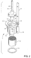
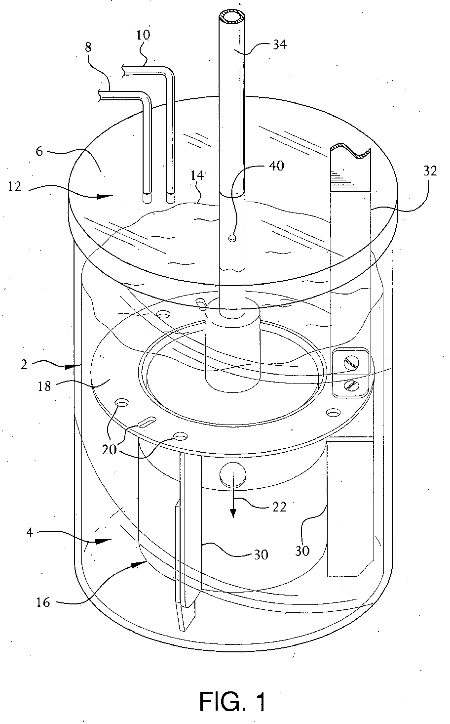
- Fig. 1-3 describe an autoclave 2 which is of conventional configuration including a fixed bed catalyst holder 4.
- the autoclave 2 has an opening typically at the top to gain access to the interior and a cover 6 for closing the opening.
- Inlet and exit lines 8 and 10 are provided to introduce reactants to autoclave 2 and to remove product.
- the inlet and exit lines 8 and 10 can be one in the same, but it is preferred they are separate. There may be more than one inlet and one exit line and the number is at the discretion of the designer of the autoclave. Often there is a sampling line (not shown) that provides access for taking samples and monitoring the reaction.
- the autoclave typically is cylindrical in configuration but other variations are possible.
- Heat exchangers either internal (coils) or external (jacketed) to the autoclave are commonly provided to maintain the temperature of the reactor contents. Sufficient reactive liquid(s) then is provided in the autoclave to fully submerge the fixed bed catalyst holder 4 and, yet, leave room for the collection of gas in headspace 12 above liquid level 14.
- the fixed bed catalyst holder 4 is comprised of a housing 16 that is open at its top and its bottom.
- a horizontal baffle 18 is positioned at an upper point on the housing and configured to the contour of the interior wall of the autoclave in order to restrict liquid flow between the edge of the horizontal baffle 18 and the interior wall of the autoclave 2. (Note the space between the edge of horizontal baffle 18 and the interior wall of autoclave 2 as shown by the arrows in Fig. 3).
- At least one, and preferably a plurality of perforations 20, is present in horizontal baffle 18 to permit upward flow of liquid and gas (as shown by the arrows) therethrough. Often, a plurality of perforations 20 is provided uniformly about the periphery of horizontal baffle 18.
- the housing 16 has at least one side wall perforation 22, preferably a plurality of perforations 22 uniformly distributed about the circumference of housing 16, extending through the side wall of the housing 16 at a point below the horizontal baffle 18 but above the outlet of a fixed bed catalyst 24 to be described.
- the sidewall perforation 22 permits flow of liquid and gas from the interior of the housing 16 to a point exterior of the housing 16 and within the autoclave 2 as shown by the arrow.
- a fixed bed catalyst 24, e.g., a monolith catalyst is placed within housing 16 in a way such that reactant liquid(s) and reactant gas can pass from the bottom of the housing 16 through the fixed bed catalyst 24 and out the side wall perforations 22 in the upper end of housing 16. Often there is a plurality of perforations 22 distributed uniformly about the periphery of housing 16.
- the fixed bed catalyst 24 is supported by threaded sealing ring 26 that engages the bottom portion of housing 16.
- a retaining ring 28 is provided to prevent upward movement of the fixed bed catalyst in the housing 16.
- a screen or grid may be placed at the top and bottom portions to retain the particulate fixed bed catalyst in place.
- Side baffles 30 are placed external to housing 16 and are used to direct gas and liquid in an axial and downward flow direction and generally opposite the direction of gas and liquid flow in the fixed bed catalyst 28. If desired, side baffles 30 are vertically positioned and extend below the bottom of housing 16 for supporting and maintaining housing 16 from sealing engagement with the bottom of autoclave 2. (Other means than side baffles 30 may be used to provide support for housing 16.) It is necessary to maintain a space between the bottom of the housing 16 to permit flow of liquid and gas there between. The use of the side baffles 30 thus not only provides for support but for effecting liquid and gas flow direction. Side baffling may also be positioned on the interior walls of the autoclave and are deemed equivalent to those positioned on housing 16 but it is preferred to have baffling affixed to the housing 16.
- a support arm 32 is provided so that attachment (not shown) may be made to the autoclave itself.
- Other means than support arm 32 may be used to maintain the fixed bed catalyst holder 4 in a fixed location.
- the housing 16 is designed such that minimal gas and liquid can pass between the outer edge of the fixed bed catalyst 24, e.g., a monolith catalyst and the interior wall of housing 16. In that way a substantial portion of the reactant liquid(s), reactant gas and product is forced through the fixed bed catalyst.
- agitator shaft 34 has an axial passageway 38 that is positioned for discharge of gas at or near turbine blade 36 at one end and inlet 40 at another point in headspace 12 of autoclave 2.
- the axial passageway 38 is internal to agitator shaft 34 but it can also be a tube, etc. external thereto. The axial passageway 38 thus provides for a flow of reactant gas from the headspace 12 to the turbine blade 36.
- the agitation system provides the driving force necessary for catalytic reaction.
- turbine blade 36 typically a disc or vane impeller, which is positioned proximate and adjacent side wall perforations 22 in housing 16 forces liquid and gas radially and outwardly through side wall perforations 22. This action causes liquid reactant above horizontal baffle 18 to be drawn into the upper opening of housing 16.
- Reactant gas also is drawn from the headspace 12 through the axial passageway 38 in shaft 34 and discharged at a point adjacent turbine 34.
- Gas inlet 40 allows introduction of gas from the headspace 12 to passageway 38. Impingement of reactant liquid and reactant gas with the turbine blade 36 generates a frothy and intimate mixture of finely divided gas bubbles and reactant liquid.
- an upper flow pattern is established by the agitation system.
- the agitation system also creates a second flow pattern.
- the frothy mixture of reactant gas and reactant liquid after exiting housing 16 through side wall perforations 22, is directed downwardly within autoclave 2 and external to housing 16.
- the frothy mixture passes beneath the housing 16 and into the interior. Then, the mixture is passed upwardly through the fixed bed catalyst 24.
- This flow pattern is established by virtue of horizontal baffle 18 and side baffles 30. Too much space between the wall of autoclave 2 and horizontal baffle 18 and the wall and side baffle 30 may detract from the desired downward flow of reactants.
- the flow pattern can also be disrupted by not including side baffles. Without side baffles the frothy mixture tends to swirl and avoid passing through the fixed bed catalyst 24.
- the reactants pass through the fixed bed catalyst 24 and contacted with the active component from inlet to outlet.
- reaction can be carried out in the retrofitted autoclave.
- One class of reaction is the hydrogenation of organic compounds, which includes hydrogenation of a mixture of immiscible liquids.
- Commonly used solvents in slurry phase and fixed bed catalytic reactions may be used in the process if the presence of immiscible liquids cause problems. Examples of commonly used solvents include lower alkanols, e.g., methanol, ethanol and propanol, iso or normal; tetrahydrofuran and glycols, e.g., ethylene glycol and diethylene glycol.
- the amount of solvent used in hydrogenation reactions for example typically ranges from 1 to about 50% by weight of the charge.
- Olefins are another group and these include straight chain, cyclic and aromatics. Examples include toluene, benzene and nitro, carboxyl, hydroxyl and amine derivatives thereof such as aniline, toluidine, toluenediamine, mononitrotoluene, nitrobenzoic acid and so forth.
- Anhydrides such as maleic anhydride and phthalic anhydride are first hydrogenated to ⁇ -butyrolactone and phthalide respectively.
- the ⁇ -butyrolactone can be further reduced to tetrahydrofuran.
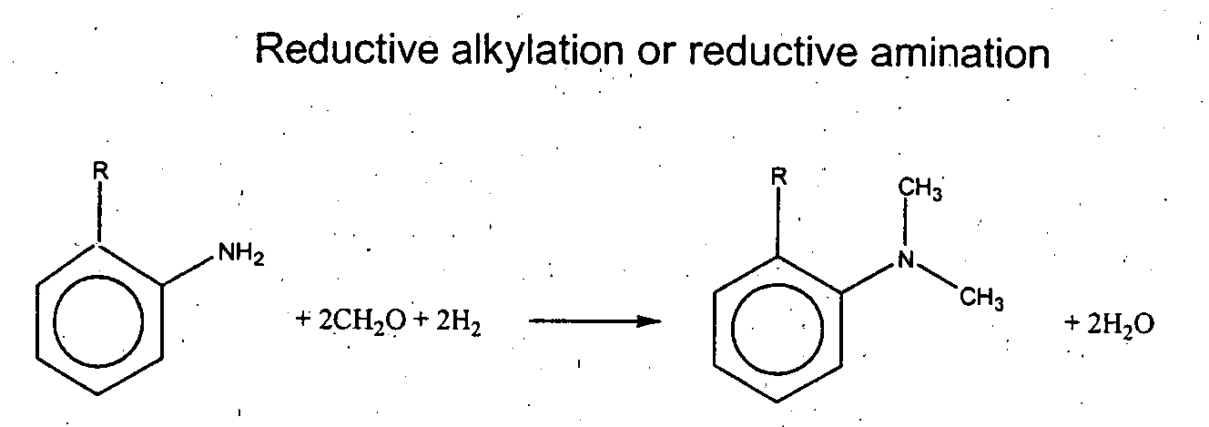
- R and R' can be aromatic or aliphatic.
- aldehydes and ketones useful in the hydrogenation reactions include formaldehyde, cyclohexanone and methyl isopropyl ketone.
- Reaction products resulting from the reaction of these aldehydes and ketones with primary and secondary amines include N-methylcyclohexylamine, N-methyldicyclohexylamine, N,N-dimethylcyclohexylamine, N-ethylcyclohexylamine, dicyclohexylamine, N,N-diethylcyclohexylamine, N,N,N-trimethylaminoethylethanolamine, N-ethyl-1,2-dimethylpropylamine and N,N,N',N'-tetramethylpropanediamine.
- One class of fixed bed catalytic reactor suited for effecting a retrofit of the stirred tank, slurry phase reactor is a monolith catalytic reactor. These reactors broadly are classified as continuous solid phase and continuous void phase from an inlet to an outlet.
- the monolith catalysts consist of an inorganic porous substrate, a metallic substrate, or a modified substrate having a plurality of channels coated with a catalytic metal. The modification can be an inorganic coating derived from a carbon or a heat treated network polymer.
- the monolith catalytic reactors are based upon long narrow capillary channels, circular, square, rectangular or other geometric shape, whereby gas and liquid are co-currently passed through the channels under a laminar flow regime. These channels are present within arrange of from 100 to 1500, preferably from 400 to 800 channels per square inch.
- fixed bed catalyst examples include pellets, spheres, as well as coated substrates, e.g., rings and saddles, wire mesh, etc.
- the metal catalytic component also may be incorporated onto particulate supports. Examples of supports include alumina, silica, kieselguhr, clays, diatomaceous earth, zeolites, e.g., X, Y, A and ZSM; carbon, and polymeric. Catalytic metals may also be deposited on or impregnated into particulate supports or they may be particulate in themselves. Screens or other systems conventionally employed for retaining the particulate catalyst components in the catalyst holder may be used.
- Catalytic metals suited for incorporation into the monolith catalytic reactor or onto supports, for effecting reactions such as hydrogenation include: Group VIb, Group VIIb, Group VIII, and Group Ib metals of the periodic table.
- Examples of catalytic metal components include cobalt, nickel, Raney or sponge nickel, palladium, platinum, copper, rhodium, ruthenium, rhenium and so forth. Often a mixture of metals are employed, one example being palladium and nickel.
- Catalytic metals are impregnated into the monolith substrate via a washcoat.
- the washcoat composition comprised of catalytic metals is typically identified as a weight percent within the washcoat itself. The washcoat may be applied in an amount of from 1 to 50% of the monolith total weight.
- Typical catalyst metal loadings range from 0.1 to 25% by weight and preferably from 1 to 10% by weight of the washcoat.
- the catalytic metals may be incorporated into the monolith substrate or support in a manner generally recognized by the art. Incipient wetness from a salt solution of the catalytic metal is one example of a method for incorporating a metal catalytic component on the monolith substrate or modified monolith substrate.
- the fixed bed catalyst is sized that it has a catalyst volume typically from about 5 to 50 percent of the volume of the autoclave. This volume allows for excellent circulation rate through the catalyst bed, e.g., 0.1 seconds to about 5 seconds with a liquid velocity of from 0.01 to 1 meter/second. An overall gas hold-up of from 5 to 50% in the stirred tank reactor is preferred.
- a 2-inch long x 2-inch diameter 5% Pd/carbon monolith catalyst having 400 channels per square inch was mounted in the fixed bed catalyst holder described in Fig. 1 providing an effective monolith catalyst diameter of 1.75 inches.
- This assembly- was placed in the 2 L Parr reactor and sealed. After room temperature dry leak testing with nitrogen, then hydrogen, then depressurizing, one liter of 2-propanol was added to the reactor.
- the reactor was pressurized to 200 psig with hydrogen, heated over 30 minutes to 140°C with stirring at 1000 rpm, maintained at 140°C for 30 minutes, and then cooled to room temperature. The reactor was emptied.
- Parr reactor including the monolith catalyst was added one liter of 40 wt% nitrobenzene in 2-propanol (364.7 g nitrobenzene plus 548.3 g of 2-propanol) to provide a liquid level above the horizontal baffle.
- the Parr reactor was sealed, pressurized with hydrogen to 35 psig and heated to 140°C over 30 minutes. The pressure was increased with hydrogen to 200 psig with stirring maintained at 1000 rpm.
- the action of the turbine impeller creates a low pressure zone at the point of agitation. That action causes hydrogen to be drawn from the headspace through the passageway in the agitator shaft and dispensed adjacent the turbine. Also, reactor liquid above the horizontal baffle is drawn to the turbine impeller. Rotation of the turbine causes the hydrogen to break into finely divided bubbles and cause dissolution of hydrogen in the liquid nitrobenzene phase. In doing so, a frothy mixture is created. Because of the restriction of liquid flow upward into an upper part of the autoclave by the horizontal baffle, a major portion of the frothy mixture is forced downwardly to the bottom of housing. The resultant reaction mixture then passes to the inlet of the monolith catalyst, then upwardly through the monolith catalyst to the outlet. The reaction product comprised of aniline, unreacted nitrobenzene and hydrogen are removed at the outlet of the monolith catalyst. The process is repeated with the reaction mixture and incoming reactant from above the horizontal baffle being discharged through the side wall perforation in the housing.
- a portion of the frothy mixture exiting the side wall perforations in the housing is allowed to pass to an upper portion of the autoclave by virtue of the perforations in the horizontal baffle. Unreacted hydrogen is vented to the headspace and liquid flows to an upper portion of the housing.
- Hydrogen uptake is monitored using a ballast and hydrogenation is complete after 40 minutes at 140°C minutes in the Parr reactor.
- the hydrogen uptake throughout the reaction was between 50 and 75 moles H 2 /m 3 of catalyst/ sec. At that point, the reaction was terminated and the product removed from the Parr reactor.
Landscapes
- Chemical & Material Sciences (AREA)
- Organic Chemistry (AREA)
- Chemical Kinetics & Catalysis (AREA)
- Organic Low-Molecular-Weight Compounds And Preparation Thereof (AREA)
- Physical Or Chemical Processes And Apparatus (AREA)
- Mixers Of The Rotary Stirring Type (AREA)
- Low-Molecular Organic Synthesis Reactions Using Catalysts (AREA)
- Devices And Processes Conducted In The Presence Of Fluids And Solid Particles (AREA)
Abstract
Description
- an ability to retrofit stirred tank reactors and autoclaves thereby converting them from slurry phase catalytic reactors to fixed bed catalytic reactors;
- an ability to eliminate reactor loops, pumps, etc. commonly used in fixed bed and monolith catalytic reactors, particularly those that employ external heat exchangers;
- an ability to enhance the solubilization of the reactant gas in the reactant liquid for catalytic reaction;
- an ability to maintain homogeneity of the reactants and reaction products;
- an ability to enhance circulation rate and effect short mixing and blend times due to the high flow rate generated by the turbine impeller through a fixed bed catalytic reactor;
- an ability to perform two phase reactions in an autoclave using a fixed bed catalyst, e.g., a monolith catalyst; and,
- an ability to overcome agitation problems where the fixed bed catalytic reactor is affixed to the agitation mechanism and rotated.
RNO2 + 3H2 → RNH2 + 2H2O



Claims (12)
- An apparatus for effecting a reaction between a reactant gas and a reactant liquid in a stirred autoclave which includes a catalyst holder which comprises:an autoclave having an opening therein to permit access to its interior, a cover for the opening and at least one line to introduce reactants and remove product;a fixed bed catalyst holder disposed within the autoclave comprised of a housing that is open at its top and at its bottom and having at least one side wall perforation at an upper portion of the housing and extending through the housing to permit flow of reactant liquid and reactant gas from the bottom of the housing and then from the interior of the housing to a point exterior of the housing;a horizontal baffle connected at upper portion of the housing above said side wall perforation, the baffle configured to the contour of the interior wall of the autoclave to limit flow of reactant gas and reactant liquid between the edge of the baffle and the interior wall of the autoclave, said baffle having at least one perforation present in the baffle to permit flow of reactant liquid and reactant gas therethrough;a side baffle external to the housing or affixed to the interior wall of the autoclave for directing reactant gas and reactant liquid downwardly from said side wall perforation to the inlet of the fixed bed catalyst;an agitation system that includes a motor, an agitation shaft extending into the autoclave terminating in a turbine impeller; and,a fixed bed catalyst retained within the housing to permit reactant liquid and reactant gas to pass from the bottom of the housing through the fixed bed catalyst and out the upper end of the fixed bed catalyst.
- The apparatus of Claim 1 wherein said agitator shaft incorporates a passageway having an end terminating for discharge at said turbine impeller and terminating at another point near an upper portion and into the headspace of said autoclave, said turbine positioned adjacent the at least one side wall perforation in said housing such that reactant liquid and reactant gas are forced outwardly through said side wall perforation by said turbine impeller and against the interior wall of the autoclave.
- The apparatus of Claim 2 wherein there is a plurality of perforations substantially uniformly distributed about the side wall of said housing for permitting a mixture of reactant liquid and reactant gas to flow therethough.
- The apparatus of Claim 3 wherein the horizontal baffle has a plurality of perforations substantially uniformly distributed for permitting flow of a reactant liquid and reactant gas upward and downward in the autoclave.
- The apparatus of Claim 4 wherein the fixed bed catalyst is a monolith catalytic reactor comprised of a monolith substrate and a catalytic metal.
- The apparatus of Claim 5 wherein the catalytic metal in said monolith catalytic reactor is selected from the group consisting of VIb, Group Vllb, Group VIII, and Group Ib metals of the periodic table.
- The apparatus of Claim 6 wherein the catalytic metal is selected from the group consisting of cobalt, nickel, Raney or sponge nickel, palladium, platinum, copper, ruthenium, rhodium and rhenium.
- In a process for carrying out a reaction between a reactant gas and reactant liquid in a stirred tank having at least a portion of reactant gas residing in a headspace portion of said autoclave, the improvement which comprises:inserting a fixed bed catalyst holder in said tank comprised of a housing having an open top and open bottom portion supportably maintained with said tank, said housing having a substantially outwardly extending, horizontal baffle near its top portion and adapted for substantial sealing engagement with the interior wall of said tank, said baffle having a least one perforation in its surface, and said housing having at least one side wall perforation in the wall near its upper portion permitting flow from the interior of the housing to said tank;supportably retaining a fixed bed catalyst within said housing permitting both liquid and reactant gas flow therethrough;extending an agitator shaft into said tank and terminating in a turbine blade substantially adjacent the side wall perforation in the wall of said housing, said agitator having a gas passageway including an opening in the headspace portion of said autoclave and terminating in an opening adjacent the turbine blade;effecting agitation at a point adjacent the side wall perforation in the wall of said housing causing liquid and reactant gas to be passed from the interior of the housing through the perforations to the interior of the autoclave;drawing reactant gas hydrogen from the headspace in said autoclave through a passageway in said agitator to a point adjacent the turbine;forcing a mixture of reactant liquid and reactant gas via baffling from a point adjacent the side wall perforations in said housing to the inlet of the fixed bed catalyst by means of baffles extending from the top to at least the bottom portion of said housing; and then,reacting the mixture of reactant gas and reactant liquid.
- The process of Claim 8 wherein the reaction is a hydrogenation reaction.
- The process of Claim 9 wherein the reactant liquid is a nitroaromatic compound.
- The process of Claim 10 wherein the nitroaromatic compound is dinitrotoluene.
- The process of Claim 10 wherein the nitroaromatic compound is nitrobenzene.
Applications Claiming Priority (2)
| Application Number | Priority Date | Filing Date | Title |
|---|---|---|---|
| US76813 | 2002-02-15 | ||
| US10/076,813 US7074962B2 (en) | 2002-02-15 | 2002-02-15 | Catalyst holder and agitation system for converting stirred tank reactor to fixed bed reactor |
Publications (2)
| Publication Number | Publication Date |
|---|---|
| EP1336428A2 true EP1336428A2 (en) | 2003-08-20 |
| EP1336428A3 EP1336428A3 (en) | 2004-02-25 |
Family
ID=27622789
Family Applications (1)
| Application Number | Title | Priority Date | Filing Date |
|---|---|---|---|
| EP03002619A Withdrawn EP1336428A3 (en) | 2002-02-15 | 2003-02-10 | Catalyst holder and agitation system for converting stirred tank reactor to fixed bed reactor |
Country Status (3)
| Country | Link |
|---|---|
| US (2) | US7074962B2 (en) |
| EP (1) | EP1336428A3 (en) |
| JP (1) | JP3749523B2 (en) |
Cited By (10)
| Publication number | Priority date | Publication date | Assignee | Title |
|---|---|---|---|---|
| EP1524259A1 (en) * | 2003-10-13 | 2005-04-20 | Bayer MaterialScience AG | Process for the preparation of aromatic amines by heterogene catalyzed hydrogenation |
| FR2966752A1 (en) * | 2010-11-03 | 2012-05-04 | IFP Energies Nouvelles | Apparatus for carrying out catalytic chemical reactions/heterogeneous adsorptions with solid reaction/adsorption catalysts in heterogeneous liquid phase, comprises enclosure, liquid moving unit, axial basket, and regulation unit |
| WO2012103432A2 (en) | 2011-01-28 | 2012-08-02 | Catacel Corp. | Improved stackable structural reactors |
| CN109351311A (en) * | 2018-12-14 | 2019-02-19 | 中国科学院合肥物质科学研究院 | A metal sulfide nanomaterial synthesis device |
| WO2019199294A1 (en) * | 2018-04-11 | 2019-10-17 | W.L. Gore & Associates, Inc. | Metal supported powder catalyst matrix and processes for multiphase chemical reactions |
| DE102019207565A1 (en) * | 2019-05-23 | 2020-11-26 | Friedrich-Alexander-Universität Erlangen-Nürnberg | Berty reactor and kit for one |
| CN117925397A (en) * | 2024-02-18 | 2024-04-26 | 中国标准化研究院 | High-efficiency biocatalysis reactor |
| WO2024097633A1 (en) * | 2022-10-31 | 2024-05-10 | W. L. Gore & Associates, Inc. | Catalytic membrane and reactors comprising the same |
| CN118145899A (en) * | 2024-03-22 | 2024-06-07 | 中国冶金地质总局山东局集团青岛有限公司 | A method for proportioning all-solid waste curing agent for construction and its preparation system |
| CN120885177A (en) * | 2025-09-28 | 2025-11-04 | 东力(南通)化工有限公司 | A catalytic reactor for the production of methylhydrazine and its usage method |
Families Citing this family (14)
| Publication number | Priority date | Publication date | Assignee | Title |
|---|---|---|---|---|
| JP4354341B2 (en) * | 2004-06-11 | 2009-10-28 | 花王株式会社 | Reactor |
| US7585338B2 (en) * | 2005-01-21 | 2009-09-08 | Atuhiro Yoshizaki | Hydrogen generating apparatus |
| US20060229476A1 (en) | 2005-04-08 | 2006-10-12 | Mitchell Robert L Sr | Activated carbon monolith catalyst, methods for making same, and uses thereof |
| EP2116591A1 (en) * | 2008-05-05 | 2009-11-11 | Rohm and Haas Company | Method for Esterification of Fatty Acids in Glyceryl Esters in A Tubular Reactor |
| US9126168B2 (en) | 2010-12-15 | 2015-09-08 | Exxonmobil Research And Engineering Company | Catalyst bed platform with center support pipe |
| CN103446957B (en) | 2012-05-28 | 2015-08-19 | 中国石油天然气股份有限公司 | A swirl type cold hydrogen box propelled by cold hydrogen |
| HUE030188T2 (en) * | 2013-01-22 | 2017-04-28 | Covestro Deutschland Ag | Method for manufacturing aromatic amines |
| US9222924B1 (en) * | 2013-07-30 | 2015-12-29 | E3Tec Service, Llc | Differential kinetic test unit |
| EP3224196B1 (en) * | 2014-11-28 | 2018-08-22 | Ulusal Bor Arastirma Enstitusu (Boren) | A cartridge structure designed for generation of hydrogen gas |
| CN105664812A (en) * | 2016-04-07 | 2016-06-15 | 江苏浩特隆搅拌设备有限公司 | Enamel kettle baffle device |
| DE102016210224A1 (en) * | 2016-06-09 | 2017-12-14 | Friedrich-Alexander-Universität Erlangen-Nürnberg | Reactor and method for the implementation of equilibrium-limited reactions |
| CN108927075A (en) * | 2018-08-02 | 2018-12-04 | 武汉中智德远科技开发有限公司 | A kind of Chemical Manufacture high-pressure stirring reaction kettle |
| CN109775766B (en) * | 2018-12-29 | 2021-04-06 | 南通北新新能源科技有限公司 | Method for rapidly recovering nickel and cobalt elements in ternary battery material |
| JP7733917B2 (en) * | 2022-06-22 | 2025-09-04 | 株式会社アクト | Separation device |
Family Cites Families (8)
| Publication number | Priority date | Publication date | Assignee | Title |
|---|---|---|---|---|
| US4594228A (en) * | 1984-05-21 | 1986-06-10 | The Standard Oil Company | Mixing apparatus |
| GB2168904B (en) * | 1984-11-30 | 1988-01-27 | Ceskoslovenska Akademie Ved | Method of circulation of liquid phase through a solid phase particularly for biocatalytical reactions and a device for realization thereof |
| US4743577A (en) * | 1986-10-14 | 1988-05-10 | Amoco Corporation | Catalyst composition |
| DE4435839A1 (en) * | 1994-10-07 | 1996-04-11 | Bayer Ag | Sludge phase reactor and its use |
| JPH10170497A (en) * | 1996-12-06 | 1998-06-26 | Idemitsu Kosan Co Ltd | Apparatus for evaluating solid catalyst and method for evaluating solid catalyst using the same |
| NL1004961C2 (en) | 1997-01-09 | 1998-07-13 | Dsm Nv | Monolith reactor. |
| DE10104849A1 (en) | 2000-02-09 | 2001-07-26 | Roland Adler | Modular gradient-free test reactor used for heterogeneous gas catalytic reactions comprises rotational mixer and propulsion jet mixer arranged in housing |
| US6790417B2 (en) * | 2000-12-21 | 2004-09-14 | Corning Incorporated | Monolith loop reactors |
-
2002
- 2002-02-15 US US10/076,813 patent/US7074962B2/en not_active Expired - Lifetime
-
2003
- 2003-02-10 EP EP03002619A patent/EP1336428A3/en not_active Withdrawn
- 2003-02-17 JP JP2003038207A patent/JP3749523B2/en not_active Expired - Fee Related
-
2006
- 2006-01-09 US US11/327,926 patent/US20060104873A1/en not_active Abandoned
Cited By (16)
| Publication number | Priority date | Publication date | Assignee | Title |
|---|---|---|---|---|
| EP1524259A1 (en) * | 2003-10-13 | 2005-04-20 | Bayer MaterialScience AG | Process for the preparation of aromatic amines by heterogene catalyzed hydrogenation |
| FR2966752A1 (en) * | 2010-11-03 | 2012-05-04 | IFP Energies Nouvelles | Apparatus for carrying out catalytic chemical reactions/heterogeneous adsorptions with solid reaction/adsorption catalysts in heterogeneous liquid phase, comprises enclosure, liquid moving unit, axial basket, and regulation unit |
| WO2012103432A2 (en) | 2011-01-28 | 2012-08-02 | Catacel Corp. | Improved stackable structural reactors |
| EP2667962A4 (en) * | 2011-01-28 | 2018-04-04 | Johnson Matthey Public Limited Company | Improved stackable structural reactors |
| US11607662B2 (en) | 2018-04-11 | 2023-03-21 | W. L. Gore & Associates, Inc. | Metal supported powder catalyst matrix and processes for multiphase chemical reactions |
| WO2019199294A1 (en) * | 2018-04-11 | 2019-10-17 | W.L. Gore & Associates, Inc. | Metal supported powder catalyst matrix and processes for multiphase chemical reactions |
| EP4234077A3 (en) * | 2018-04-11 | 2023-10-25 | W. L. Gore & Associates, Inc. | Metal supported powder catalyst matrix and processes for multiphase chemical reactions |
| US11224853B2 (en) | 2018-04-11 | 2022-01-18 | W. L. Gore & Associates, Inc. | Metal supported powder catalyst matrix and processes for multiphase chemical reactions |
| US11590473B2 (en) | 2018-04-11 | 2023-02-28 | W. L. Gore & Associates, Inc. | Metal supported powder catalyst matrix and processes for multiphase chemical reactions |
| CN109351311A (en) * | 2018-12-14 | 2019-02-19 | 中国科学院合肥物质科学研究院 | A metal sulfide nanomaterial synthesis device |
| CN109351311B (en) * | 2018-12-14 | 2023-09-08 | 中国科学院合肥物质科学研究院 | A metal sulfide nanomaterial synthesis device |
| DE102019207565A1 (en) * | 2019-05-23 | 2020-11-26 | Friedrich-Alexander-Universität Erlangen-Nürnberg | Berty reactor and kit for one |
| WO2024097633A1 (en) * | 2022-10-31 | 2024-05-10 | W. L. Gore & Associates, Inc. | Catalytic membrane and reactors comprising the same |
| CN117925397A (en) * | 2024-02-18 | 2024-04-26 | 中国标准化研究院 | High-efficiency biocatalysis reactor |
| CN118145899A (en) * | 2024-03-22 | 2024-06-07 | 中国冶金地质总局山东局集团青岛有限公司 | A method for proportioning all-solid waste curing agent for construction and its preparation system |
| CN120885177A (en) * | 2025-09-28 | 2025-11-04 | 东力(南通)化工有限公司 | A catalytic reactor for the production of methylhydrazine and its usage method |
Also Published As
| Publication number | Publication date |
|---|---|
| US20030157003A1 (en) | 2003-08-21 |
| JP3749523B2 (en) | 2006-03-01 |
| US20060104873A1 (en) | 2006-05-18 |
| US7074962B2 (en) | 2006-07-11 |
| JP2003275577A (en) | 2003-09-30 |
| EP1336428A3 (en) | 2004-02-25 |
Similar Documents
| Publication | Publication Date | Title |
|---|---|---|
| US7074962B2 (en) | Catalyst holder and agitation system for converting stirred tank reactor to fixed bed reactor | |
| KR100655354B1 (en) | Method of Making Amines | |
| US6156933A (en) | Supercritical hydrogenation | |
| KR100339285B1 (en) | Use of a monolith catalyst for the hydrogenation of dinitrotoluene to toluenediamine | |
| JP4282200B2 (en) | Method for producing amine | |
| US6479704B1 (en) | Hydrogenation with monolith reactor under conditions of immiscible liquid phases | |
| US9295971B2 (en) | Apparatus and process for the continuous reaction of liquids with gases | |
| JP2002355554A (en) | Coated monolith substrate and monolith catalyst | |
| JP4148777B2 (en) | Method for hydrogenating liquid organic compounds | |
| JP2016510322A (en) | Apparatus and method for continuous reaction of liquid and gas | |
| CN105008037A (en) | Device and method for the continuous reaction of liquids with gases | |
| US20140200351A1 (en) | Apparatus and process for the continuous reaction of liquids with gases | |
| KR20140015473A (en) | Optimized metering of reactants for a process for preparing aromatic amines by hydrogenation of nitroaromatics | |
| US9302237B2 (en) | Apparatus and process for the continuous reaction of liquids with gases | |
| CN106883128B (en) | Method for removing heterogeneous catalyst from reaction product and method for preparing aromatic amine | |
| US6521791B1 (en) | Process for regenerating a monolith hydrogenation catalytic reactor | |
| CN111212827B (en) | Improved catalyst selectivity in the continuous hydrogenation of nitro compounds by the addition of ammonia | |
| KR100474061B1 (en) | Supercritical Hydrogenation | |
| Kazemimoghadam | Catalytic Hydrogenation of Dimethylnitrobenzene to Dimethylaniline Over Pd/C Catalysts | |
| Kazemimoghadam | CONVERSION OF DIMETHYL-NITROBENZENE TO DIMETHY LAniline, EFFECT OF SOME PROCESS CONDITION | |
| Králik et al. | 0-2.4 Catalyst deactivation in the liquid phase hydrogenation of nitrocompounds | |
| Roy | Studies in catalysis and reaction engineering on multiphase hydrogenation reactions |
Legal Events
| Date | Code | Title | Description |
|---|---|---|---|
| PUAI | Public reference made under article 153(3) epc to a published international application that has entered the european phase |
Free format text: ORIGINAL CODE: 0009012 |
|
| AK | Designated contracting states |
Designated state(s): AT BE BG CH CY CZ DE DK EE ES FI FR GB GR HU IE IT LI LU MC NL PT SE SI SK TR |
|
| AX | Request for extension of the european patent |
Extension state: AL LT LV MK RO |
|
| PUAL | Search report despatched |
Free format text: ORIGINAL CODE: 0009013 |
|
| AK | Designated contracting states |
Kind code of ref document: A3 Designated state(s): AT BE BG CH CY CZ DE DK EE ES FI FR GB GR HU IE IT LI LU MC NL PT SE SI SK TR |
|
| AX | Request for extension of the european patent |
Extension state: AL LT LV MK RO |
|
| 17P | Request for examination filed |
Effective date: 20040415 |
|
| AKX | Designation fees paid |
Designated state(s): AT BE BG CH CY CZ DE DK EE ES FI FR GB GR HU IE IT LI LU MC NL PT SE SI SK TR |
|
| STAA | Information on the status of an ep patent application or granted ep patent |
Free format text: STATUS: THE APPLICATION IS DEEMED TO BE WITHDRAWN |
|
| 18D | Application deemed to be withdrawn |
Effective date: 20100901 |