EP1336382B1 - Système permettant de solidariser une barre ou analogue avec au moins une vertèbre - Google Patents
Système permettant de solidariser une barre ou analogue avec au moins une vertèbre Download PDFInfo
- Publication number
- EP1336382B1 EP1336382B1 EP03290251A EP03290251A EP1336382B1 EP 1336382 B1 EP1336382 B1 EP 1336382B1 EP 03290251 A EP03290251 A EP 03290251A EP 03290251 A EP03290251 A EP 03290251A EP 1336382 B1 EP1336382 B1 EP 1336382B1
- Authority
- EP
- European Patent Office
- Prior art keywords
- vertebra
- bar
- fact
- baseplate
- orifice
- Prior art date
- Legal status (The legal status is an assumption and is not a legal conclusion. Google has not performed a legal analysis and makes no representation as to the accuracy of the status listed.)
- Expired - Lifetime
Links
Images

Classifications
-
- A—HUMAN NECESSITIES
- A61—MEDICAL OR VETERINARY SCIENCE; HYGIENE
- A61B—DIAGNOSIS; SURGERY; IDENTIFICATION
- A61B17/00—Surgical instruments, devices or methods, e.g. tourniquets
- A61B17/56—Surgical instruments or methods for treatment of bones or joints; Devices specially adapted therefor
- A61B17/58—Surgical instruments or methods for treatment of bones or joints; Devices specially adapted therefor for osteosynthesis, e.g. bone plates, screws, setting implements or the like
- A61B17/68—Internal fixation devices, including fasteners and spinal fixators, even if a part thereof projects from the skin
- A61B17/80—Cortical plates, i.e. bone plates; Instruments for holding or positioning cortical plates, or for compressing bones attached to cortical plates
- A61B17/8085—Cortical plates, i.e. bone plates; Instruments for holding or positioning cortical plates, or for compressing bones attached to cortical plates with pliable or malleable elements or having a mesh-like structure, e.g. small strips
-
- A—HUMAN NECESSITIES
- A61—MEDICAL OR VETERINARY SCIENCE; HYGIENE
- A61B—DIAGNOSIS; SURGERY; IDENTIFICATION
- A61B17/00—Surgical instruments, devices or methods, e.g. tourniquets
- A61B17/56—Surgical instruments or methods for treatment of bones or joints; Devices specially adapted therefor
- A61B17/58—Surgical instruments or methods for treatment of bones or joints; Devices specially adapted therefor for osteosynthesis, e.g. bone plates, screws, setting implements or the like
- A61B17/68—Internal fixation devices, including fasteners and spinal fixators, even if a part thereof projects from the skin
- A61B17/70—Spinal positioners or stabilisers ; Bone stabilisers comprising fluid filler in an implant
- A61B17/7001—Screws or hooks combined with longitudinal elements which do not contact vertebrae
- A61B17/7044—Screws or hooks combined with longitudinal elements which do not contact vertebrae also having plates, staples or washers bearing on the vertebrae
-
- A—HUMAN NECESSITIES
- A61—MEDICAL OR VETERINARY SCIENCE; HYGIENE
- A61B—DIAGNOSIS; SURGERY; IDENTIFICATION
- A61B17/00—Surgical instruments, devices or methods, e.g. tourniquets
- A61B17/56—Surgical instruments or methods for treatment of bones or joints; Devices specially adapted therefor
- A61B17/58—Surgical instruments or methods for treatment of bones or joints; Devices specially adapted therefor for osteosynthesis, e.g. bone plates, screws, setting implements or the like
- A61B17/68—Internal fixation devices, including fasteners and spinal fixators, even if a part thereof projects from the skin
- A61B17/80—Cortical plates, i.e. bone plates; Instruments for holding or positioning cortical plates, or for compressing bones attached to cortical plates
- A61B17/809—Cortical plates, i.e. bone plates; Instruments for holding or positioning cortical plates, or for compressing bones attached to cortical plates with bone-penetrating elements, e.g. blades or prongs
Definitions
- the present invention relates to systems for securing a bar or analog with at least one vertebra, which find an application particularly advantageous for maintaining at least two vertebrae, consecutive or not, in relation to each other in order to achieve a spinal arthrodesis, for example in a human being for the purpose of delete for example the cause of pain generated by intervertebral disc damaged or fractured vertebra, or to treat scoliosis or kyphosis or to avoid the risk of paralytic complications related to this fracture.
- Practitioners in the field of osteo-spinal surgery use in particular a system consisting of plates in which are practiced an orifice and a light, and screws each comprising a threaded rod bone terminated by a shoulder head, these screws being able to cooperate with the plates by screwing themselves into the bones of the vertebral bodies so that these plates are trapped in support between the vertebrae and the shoulder heads of the screw.
- This system of spinal osteosynthesis is interesting but can in certain cases have disadvantages, in particular because it requires the implantation of screws in the vertebral bodies, implantation which can be revealed risky and difficult given the configuration of these vertebral bodies and / or lead to serious complications.
- the present invention therefore aims to provide a system for to secure a bar or the like with at least one vertebra, which overcomes at least in part the disadvantages mentioned above of osteosynthesis systems spinal cord according to the prior art.
- the present invention relates to a system for securing a bar or the like with at least one vertebra in with the content of the attached claim 1, the preamble of which account of the content of the prior art, and more particularly of the document American mentioned above.
- the object of the invention comprises "at least one" element having a given function
- the mode described embodiment may include several of these elements.
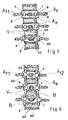
- Figures 1, 3 and 4 show three embodiments of a system for securing a bar B or the like with at least one vertebra V, which comprises a base 1 substantially U-shaped comprising a bottom 2 and two branches lateral 3, 4 secured to two opposite edges of this bottom.
- the base 1 is shaped so that its bottom 2 comes into recovery of the posterior part of the vertebra V by at least partially surrounding its spinous process A e and that its two lateral branches 3, 4 are positioned on either side vertebra V surrounding at least partially respectively its two transverse processes At1, At2, and so that these two lateral branches 3, 4 are supported by pinching laterally on at least one of the following elements: the two faces 5, 6 the farthest from each other of the two pedicles 7, 8 and on the transverse processes of the vertebra V.
- the system further comprises means 9 for fixing the bar B with the base 1.
- means 9 for fixing the bar B with the base 1.
- the two lateral branches 3, 4 of the base 1 can take several forms, but are advantageously each constituted by at least two lugs 21, 22 integral with the bottom 2, the two legs 21, 22 being spaced from each other so that they are able to position themselves on either side of a transverse process A t1 , A t2 .
- the bottom 2 of the base 1 is shaped so that it overlaps the posterior portion of the vertebra V by at least partially surrounding the spinous process A e of this vertebra. Also, in a possible embodiment as illustrated in Figure 1, to achieve this function, the bottom 2 has an open light 23 for the passage of the spinous apophysis A e , while in both Figures 3 and 4, this light is closed.
- the lateral branches 3, 4 are made of an elastically deformable material to constitute the branches of an elastic clip which can then be perfectly pressed in force against both sides 5, 6 pedicles and thus ensure the positioning of the base on the vertebra V.
- This elastically deformable material can be for example titanium or the like, knowing that the base 1 can be made of a single piece in the same material, or an assembly of several pieces, by example of formed rods and plates.
- the base 1 is constituted, as illustrated in FIG. 3, two half-U 24, 25 and means 26 to couple the two half-U by their bottom.
- These means 26 for coupling the two half-U by their bottom can be constituted in different ways.
- they may consist of two holes each made in the bottom of a half-U 24, 25, the first hole, the one that is made in the bottom of the half-U which is located towards the inside of the U-shape of the reconstituted base being tapped, while that the second hole is of generally oblong shape, and a screw with conical head fit to screw into the first hole.
- the conical head bears against one side of the second hole oblong to translate, as and when screwing, the bottom half-U in which is made this second hole, on the bottom of the half-U in which is realized the first hole.
- the system further comprises means 9 to fix the bar B with the base 1.
- These means 9 include, in a preferred embodiment, an orifice 27 made in the base 1, an oblong piece 30, a first end 31 is crimped, advantageously in rotation, in the orifice 27, its second end 32 being configured as jumper 33 with two lateral arms 34, 35, this jumper being adapted to receive the bar B between its two arms, FIG. 2, and means 36 for secure the bar B with this jumper 33.
- the orifice 27 is an orifice oblong.
- the means 36 for to secure the bar B with the jumper 33 are constituted for example by means 39 for bringing the two lateral arms 34, 35 of the rider 33 into view to clamp the bar B.
- These means 39 to bring the two arms 34, 35 are advantageously constituted for example by a nut 40 with conical thread or analog able to be screwed on the outer faces of the two arms 34, 35.
- the system further comprises pins 37 lining the inner wall 38 of the base 1.
- the practitioner begins by choosing the bases that have a size and configuration that allow them to cover and to pinch as described above the vertebrae V which must be subjected to a arthrodesis.
- these bases are themselves integral with the three vertebrae, these three vertebrae are perfectly maintained relative to each other to others and the arthrodesis can thus be realized, and this, without having difficulty for the implantation of the bases because each stabilizes immediately by compared to the vertebra on which it was placed, and without having to pierce the vertebral body.
Description
Claims (9)
- Système permettant de solidariser une barre (B) ou analogue avec au moins une vertèbre (V), comportant au moins une embase (1) agencée pour venir en recouvrement de la partie postérieure de la vertèbre en entourant au moins partiellement l'apophyse épineuse (Ae) de ladite vertèbre (V) et des moyens (9) pour fixer ladite barre (B) avec ladite embase (1), caractérisé par le fait que ladite embase (1) présente une forme sensiblement de "U" comportant un fond (2) et deux branches latérales (3, 4) solidaires de deux bords opposés du fond, ledit fond (2) venant en recouvrement de la partie postérieure de la vertèbre en entourant au moins partiellement l'apophyse épineuse (Ae) et les deux branches latérales (3, 4) venant se positionner de part et d'autre de la vertèbre en entourant au moins partiellement respectivement ses deux apophyses transverses (At1, At2), et de façon que ces deux branches latérales (3, 4) prennent appui latéralement en pincement, pour solidariser ladite embase à la vertèbre sans ajout d'éléments annexes, sur au moins l'un des éléments suivants: les deux faces (5, 6) les plus éloignées l'une de l'autre des deux pédicules (7, 8) et les apophyses transverses de la vertèbre (V).
- Système selon la revendication 1, caractérisé par le fait qu'au moins une branche latérale (3, 4) est constituée d'au moins deux pattes (21, 22) solidaires du fond (2), les deux dites pattes (21, 22) étant espacées l'une de l'autre de façon qu'elles soient aptes à se positionner de part et d'autre d'une apophyse transverse (At1, At2)
- Système selon l'une des revendications 1 et 2, caractérisé par le fait que ledit fond (2) comporte une lumière (23) pour le passage de l'apophyse épineuse (Ae).
- Système selon l'une des revendications 1 à 3, caractérisé par le fait qu'au moins les branches latérales (3, 4) sont réalisées en matériau élastiquement déformable.
- Système selon l'une des revendications 1 à 4, caractérisé par le fait que l'embase (1) est constituée de deux demi-U (24, 25) et de moyens (26) pour accoupler les deux demi-U par leur fond.
- Système selon l'une des revendications 1 à 5, caractérisé par le fait que les moyens (9) pour fixer la barre (B) avec l'embase comportent un orifice (27) réalisé dans l'embase (1), une pièce oblongue (30) dont une première extrémité (31) est sertie en rotation dans l'orifice (27), sa seconde extrémité (32) étant conformée en cavalier (33) à deux bras latéraux (34, 35), ledit cavalier étant apte à recevoir la barre (B) entre ses deux bras, et des moyens (36) pour solidariser la barre (B) avec le cavalier (33).
- Système selon la revendication 6, caractérisé par le fait que les moyens (36) pour solidariser la barre (B) avec le cavalier (33) sont constitués par des moyens (39) pour pincer les deux bras latéraux (34, 35) sur la barre (B).
- Système selon l'une des revendications 6 et 7, caractérisé par le fait que l'orifice (27) est un orifice oblong.
- Système selon l'une des revendications 1 à 8, caractérisé par le fait qu'il comporte des picots (37) tapissant la paroi intérieure (38) de l'embase (1).
Applications Claiming Priority (2)
| Application Number | Priority Date | Filing Date | Title |
|---|---|---|---|
| FR0201749 | 2002-02-13 | ||
| FR0201749A FR2835736B1 (fr) | 2002-02-13 | 2002-02-13 | Systeme permettant de solidariser une barre ou analogue avec au moins une vertebre |
Publications (2)
| Publication Number | Publication Date |
|---|---|
| EP1336382A1 EP1336382A1 (fr) | 2003-08-20 |
| EP1336382B1 true EP1336382B1 (fr) | 2005-09-07 |
Family
ID=27620149
Family Applications (1)
| Application Number | Title | Priority Date | Filing Date |
|---|---|---|---|
| EP03290251A Expired - Lifetime EP1336382B1 (fr) | 2002-02-13 | 2003-02-03 | Système permettant de solidariser une barre ou analogue avec au moins une vertèbre |
Country Status (4)
| Country | Link |
|---|---|
| EP (1) | EP1336382B1 (fr) |
| AT (1) | ATE303766T1 (fr) |
| DE (1) | DE60301507D1 (fr) |
| FR (1) | FR2835736B1 (fr) |
Family Cites Families (3)
| Publication number | Priority date | Publication date | Assignee | Title |
|---|---|---|---|---|
| FR2761876B1 (fr) * | 1997-04-09 | 1999-08-06 | Materiel Orthopedique En Abreg | Instrumentation d'osteosynthese lombaire pour la correction du spondylolisthesis par voie posterieure |
| DE10003968A1 (de) * | 2000-01-25 | 2001-08-09 | Biomet Merck Deutschland Gmbh | Osteosynthese-Platte |
| US6533787B1 (en) * | 2000-07-31 | 2003-03-18 | Sdgi Holdings, Inc. | Contourable spinal staple with centralized and unilateral prongs |
-
2002
- 2002-02-13 FR FR0201749A patent/FR2835736B1/fr not_active Expired - Fee Related
-
2003
- 2003-02-03 AT AT03290251T patent/ATE303766T1/de not_active IP Right Cessation
- 2003-02-03 EP EP03290251A patent/EP1336382B1/fr not_active Expired - Lifetime
- 2003-02-03 DE DE60301507T patent/DE60301507D1/de not_active Expired - Lifetime
Also Published As
| Publication number | Publication date |
|---|---|
| ATE303766T1 (de) | 2005-09-15 |
| DE60301507D1 (de) | 2005-10-13 |
| EP1336382A1 (fr) | 2003-08-20 |
| FR2835736A1 (fr) | 2003-08-15 |
| FR2835736B1 (fr) | 2004-10-29 |
Similar Documents
| Publication | Publication Date | Title |
|---|---|---|
| EP1113758B1 (fr) | Dispositif d'osteosynthese rachidienne posterieure | |
| EP0645986B1 (fr) | Appareil de traitement du rachis | |
| CA2133766C (fr) | Dispositif d'osteosynthese rachidienne | |
| EP1439790B9 (fr) | Appareil de maintien du rachis a assemblage par coincement | |
| EP1250101B1 (fr) | Dispositif de liaison intervertebrale avec une barre de connexion pour la fixation d'une tige de liaison | |
| EP0443894B1 (fr) | Dispositif d'ostéosynthèse pour la correction des déviations rachidiennes | |
| CA2374988C (fr) | Plaque d'osteosynthese vertebrale et systeme d'osteosynthese | |
| FR2781359A1 (fr) | Materiel d'osteosynthese rachidienne | |
| EP0596788B1 (fr) | Dispositif d'ostéosynthèse pour consolidation rachidienne | |
| FR2651992A1 (fr) | Implant pour osteosynthese rachidienne dorso-lombaire anterieure destine a la correction de cyphoses. | |
| EP1138268A1 (fr) | Dispositif de fixation d'une cale inter épineuse sur le sacrum | |
| CA2289571A1 (fr) | Implant pour dispositif d'osteosynthese, du type a crochet | |
| FR2459650A1 (fr) | Dispositif intramedullaire de compression pour fracture des os | |
| EP0841876B1 (fr) | Connecteur pour instrumentation d'osteosynthese rachidienne, destine a une fixation lombaire ou sacree ou ilio-sacree | |
| EP2288302A1 (fr) | Crochet pour dispositif d'ostéosynthèse vertébrale et dispositif le comprenant | |
| WO1997005830A1 (fr) | Cheville intrafocale | |
| FR2642642A1 (fr) | Implant d'osteosynthese posterieure rachidienne | |
| WO2003032849A1 (fr) | Systeme pour maintenir au moins deux vertebres l'une par rapport a l'autre pour realiser une osteosynthese rachidienne | |
| EP1336382B1 (fr) | Système permettant de solidariser une barre ou analogue avec au moins une vertèbre | |
| WO1995032675A1 (fr) | Dispositif d'osteosynthese a coapteurs rapportes | |
| FR2783698A1 (fr) | Dispositif d'osteosynthese rachidienne avec crochet median d'ancrage sur l'arc vertebral posterieur | |
| FR2913330A1 (fr) | Dispositif d'ancrage vertebral par clou intrapediculaire | |
| FR2806902A1 (fr) | Systeme pour maintenir au moins deux portions d'os l'une par rapport a l'autre | |
| FR2835733A1 (fr) | Patte pour fixer au moins deux portions d'os l'une par rapport a l'autre | |
| FR3093283A1 (fr) | Ensemble d’ostéosynthèse pour fracture d’un humérus |
Legal Events
| Date | Code | Title | Description |
|---|---|---|---|
| PUAI | Public reference made under article 153(3) epc to a published international application that has entered the european phase |
Free format text: ORIGINAL CODE: 0009012 |
|
| AK | Designated contracting states |
Designated state(s): AT BE BG CH CY CZ DE DK EE ES FI FR GB GR HU IE IT LI LU MC NL PT SE SI SK TR |
|
| AX | Request for extension of the european patent |
Extension state: AL LT LV MK RO |
|
| 17P | Request for examination filed |
Effective date: 20040216 |
|
| AKX | Designation fees paid |
Designated state(s): AT BE BG CH CY CZ DE DK EE ES FI FR GB GR HU IE IT LI LU MC NL PT SE SI SK TR |
|
| 17Q | First examination report despatched |
Effective date: 20040504 |
|
| GRAP | Despatch of communication of intention to grant a patent |
Free format text: ORIGINAL CODE: EPIDOSNIGR1 |
|
| GRAS | Grant fee paid |
Free format text: ORIGINAL CODE: EPIDOSNIGR3 |
|
| GRAA | (expected) grant |
Free format text: ORIGINAL CODE: 0009210 |
|
| AK | Designated contracting states |
Kind code of ref document: B1 Designated state(s): AT BE BG CH CY CZ DE DK EE ES FI FR GB GR HU IE IT LI LU MC NL PT SE SI SK TR |
|
| PG25 | Lapsed in a contracting state [announced via postgrant information from national office to epo] |
Ref country code: IT Free format text: LAPSE BECAUSE OF FAILURE TO SUBMIT A TRANSLATION OF THE DESCRIPTION OR TO PAY THE FEE WITHIN THE PRESCRIBED TIME-LIMIT;WARNING: LAPSES OF ITALIAN PATENTS WITH EFFECTIVE DATE BEFORE 2007 MAY HAVE OCCURRED AT ANY TIME BEFORE 2007. THE CORRECT EFFECTIVE DATE MAY BE DIFFERENT FROM THE ONE RECORDED. Effective date: 20050907 Ref country code: FI Free format text: LAPSE BECAUSE OF FAILURE TO SUBMIT A TRANSLATION OF THE DESCRIPTION OR TO PAY THE FEE WITHIN THE PRESCRIBED TIME-LIMIT Effective date: 20050907 Ref country code: CZ Free format text: LAPSE BECAUSE OF FAILURE TO SUBMIT A TRANSLATION OF THE DESCRIPTION OR TO PAY THE FEE WITHIN THE PRESCRIBED TIME-LIMIT Effective date: 20050907 Ref country code: GB Free format text: LAPSE BECAUSE OF FAILURE TO SUBMIT A TRANSLATION OF THE DESCRIPTION OR TO PAY THE FEE WITHIN THE PRESCRIBED TIME-LIMIT Effective date: 20050907 Ref country code: AT Free format text: LAPSE BECAUSE OF FAILURE TO SUBMIT A TRANSLATION OF THE DESCRIPTION OR TO PAY THE FEE WITHIN THE PRESCRIBED TIME-LIMIT Effective date: 20050907 Ref country code: NL Free format text: LAPSE BECAUSE OF FAILURE TO SUBMIT A TRANSLATION OF THE DESCRIPTION OR TO PAY THE FEE WITHIN THE PRESCRIBED TIME-LIMIT Effective date: 20050907 Ref country code: SI Free format text: LAPSE BECAUSE OF FAILURE TO SUBMIT A TRANSLATION OF THE DESCRIPTION OR TO PAY THE FEE WITHIN THE PRESCRIBED TIME-LIMIT Effective date: 20050907 Ref country code: IE Free format text: LAPSE BECAUSE OF FAILURE TO SUBMIT A TRANSLATION OF THE DESCRIPTION OR TO PAY THE FEE WITHIN THE PRESCRIBED TIME-LIMIT Effective date: 20050907 Ref country code: SK Free format text: LAPSE BECAUSE OF FAILURE TO SUBMIT A TRANSLATION OF THE DESCRIPTION OR TO PAY THE FEE WITHIN THE PRESCRIBED TIME-LIMIT Effective date: 20050907 |
|
| REG | Reference to a national code |
Ref country code: GB Ref legal event code: FG4D Free format text: NOT ENGLISH |
|
| REG | Reference to a national code |
Ref country code: CH Ref legal event code: EP |
|
| REG | Reference to a national code |
Ref country code: IE Ref legal event code: FG4D Free format text: LANGUAGE OF EP DOCUMENT: FRENCH |
|
| REF | Corresponds to: |
Ref document number: 60301507 Country of ref document: DE Date of ref document: 20051013 Kind code of ref document: P |
|
| PG25 | Lapsed in a contracting state [announced via postgrant information from national office to epo] |
Ref country code: SE Free format text: LAPSE BECAUSE OF FAILURE TO SUBMIT A TRANSLATION OF THE DESCRIPTION OR TO PAY THE FEE WITHIN THE PRESCRIBED TIME-LIMIT Effective date: 20051207 Ref country code: DK Free format text: LAPSE BECAUSE OF FAILURE TO SUBMIT A TRANSLATION OF THE DESCRIPTION OR TO PAY THE FEE WITHIN THE PRESCRIBED TIME-LIMIT Effective date: 20051207 Ref country code: BG Free format text: LAPSE BECAUSE OF FAILURE TO SUBMIT A TRANSLATION OF THE DESCRIPTION OR TO PAY THE FEE WITHIN THE PRESCRIBED TIME-LIMIT Effective date: 20051207 Ref country code: GR Free format text: LAPSE BECAUSE OF FAILURE TO SUBMIT A TRANSLATION OF THE DESCRIPTION OR TO PAY THE FEE WITHIN THE PRESCRIBED TIME-LIMIT Effective date: 20051207 |
|
| PG25 | Lapsed in a contracting state [announced via postgrant information from national office to epo] |
Ref country code: DE Free format text: LAPSE BECAUSE OF FAILURE TO SUBMIT A TRANSLATION OF THE DESCRIPTION OR TO PAY THE FEE WITHIN THE PRESCRIBED TIME-LIMIT Effective date: 20051208 |
|
| PG25 | Lapsed in a contracting state [announced via postgrant information from national office to epo] |
Ref country code: ES Free format text: LAPSE BECAUSE OF FAILURE TO SUBMIT A TRANSLATION OF THE DESCRIPTION OR TO PAY THE FEE WITHIN THE PRESCRIBED TIME-LIMIT Effective date: 20051218 |
|
| PG25 | Lapsed in a contracting state [announced via postgrant information from national office to epo] |
Ref country code: PT Free format text: LAPSE BECAUSE OF FAILURE TO SUBMIT A TRANSLATION OF THE DESCRIPTION OR TO PAY THE FEE WITHIN THE PRESCRIBED TIME-LIMIT Effective date: 20060207 |
|
| PG25 | Lapsed in a contracting state [announced via postgrant information from national office to epo] |
Ref country code: BE Free format text: LAPSE BECAUSE OF NON-PAYMENT OF DUE FEES Effective date: 20060228 Ref country code: LU Free format text: LAPSE BECAUSE OF NON-PAYMENT OF DUE FEES Effective date: 20060228 Ref country code: MC Free format text: LAPSE BECAUSE OF NON-PAYMENT OF DUE FEES Effective date: 20060228 |
|
| NLV1 | Nl: lapsed or annulled due to failure to fulfill the requirements of art. 29p and 29m of the patents act | ||
| PG25 | Lapsed in a contracting state [announced via postgrant information from national office to epo] |
Ref country code: HU Free format text: LAPSE BECAUSE OF FAILURE TO SUBMIT A TRANSLATION OF THE DESCRIPTION OR TO PAY THE FEE WITHIN THE PRESCRIBED TIME-LIMIT Effective date: 20060308 |
|
| GBV | Gb: ep patent (uk) treated as always having been void in accordance with gb section 77(7)/1977 [no translation filed] |
Effective date: 20050907 |
|
| REG | Reference to a national code |
Ref country code: IE Ref legal event code: FD4D |
|
| PLBE | No opposition filed within time limit |
Free format text: ORIGINAL CODE: 0009261 |
|
| STAA | Information on the status of an ep patent application or granted ep patent |
Free format text: STATUS: NO OPPOSITION FILED WITHIN TIME LIMIT |
|
| 26N | No opposition filed |
Effective date: 20060608 |
|
| PG25 | Lapsed in a contracting state [announced via postgrant information from national office to epo] |
Ref country code: CH Free format text: LAPSE BECAUSE OF NON-PAYMENT OF DUE FEES Effective date: 20070228 Ref country code: LI Free format text: LAPSE BECAUSE OF NON-PAYMENT OF DUE FEES Effective date: 20070228 |
|
| REG | Reference to a national code |
Ref country code: CH Ref legal event code: PL |
|
| BERE | Be: lapsed |
Owner name: RAZIAN, HASSAN Effective date: 20060228 |
|
| PG25 | Lapsed in a contracting state [announced via postgrant information from national office to epo] |
Ref country code: EE Free format text: LAPSE BECAUSE OF FAILURE TO SUBMIT A TRANSLATION OF THE DESCRIPTION OR TO PAY THE FEE WITHIN THE PRESCRIBED TIME-LIMIT Effective date: 20050907 |
|
| PG25 | Lapsed in a contracting state [announced via postgrant information from national office to epo] |
Ref country code: TR Free format text: LAPSE BECAUSE OF FAILURE TO SUBMIT A TRANSLATION OF THE DESCRIPTION OR TO PAY THE FEE WITHIN THE PRESCRIBED TIME-LIMIT Effective date: 20050907 |
|
| PG25 | Lapsed in a contracting state [announced via postgrant information from national office to epo] |
Ref country code: CY Free format text: LAPSE BECAUSE OF FAILURE TO SUBMIT A TRANSLATION OF THE DESCRIPTION OR TO PAY THE FEE WITHIN THE PRESCRIBED TIME-LIMIT Effective date: 20050907 |
|
| PGFP | Annual fee paid to national office [announced via postgrant information from national office to epo] |
Ref country code: FR Payment date: 20130301 Year of fee payment: 11 |
|
| REG | Reference to a national code |
Ref country code: FR Ref legal event code: ST Effective date: 20141031 |
|
| PG25 | Lapsed in a contracting state [announced via postgrant information from national office to epo] |
Ref country code: FR Free format text: LAPSE BECAUSE OF NON-PAYMENT OF DUE FEES Effective date: 20140228 |