EP1336134B1 - Climate control system and a method for controlling such - Google Patents
Climate control system and a method for controlling such Download PDFInfo
- Publication number
- EP1336134B1 EP1336134B1 EP01965789A EP01965789A EP1336134B1 EP 1336134 B1 EP1336134 B1 EP 1336134B1 EP 01965789 A EP01965789 A EP 01965789A EP 01965789 A EP01965789 A EP 01965789A EP 1336134 B1 EP1336134 B1 EP 1336134B1
- Authority
- EP
- European Patent Office
- Prior art keywords
- climate control
- room
- control unit
- climate
- detection system
- Prior art date
- Legal status (The legal status is an assumption and is not a legal conclusion. Google has not performed a legal analysis and makes no representation as to the accuracy of the status listed.)
- Expired - Lifetime
Links
Images



Classifications
-
- G—PHYSICS
- G05—CONTROLLING; REGULATING
- G05D—SYSTEMS FOR CONTROLLING OR REGULATING NON-ELECTRIC VARIABLES
- G05D23/00—Control of temperature
- G05D23/19—Control of temperature characterised by the use of electric means
- G05D23/1919—Control of temperature characterised by the use of electric means characterised by the type of controller
- G05D23/1924—Control of temperature characterised by the use of electric means characterised by the type of controller using thermal energy, the availability of which is aleatory
Definitions
- Smart windows may be commonly used in a large group of applications. Smart windows are particularly suitable for varying the intake of daylight as their transmittance of the whole or a part of the heat radiation range, may be continuously changed from transparent to non-transparent.
- One advantage with the system and method according to the invention is that they, compared to prior art devices and methods, improve the indoor comfort by providing automatic control of indoor climate parameters comprising light level, incoming daylight and temperature, according to a set of predefined control parameters that preferably are set by the local user.
- the total light level parameter 26 is a value that defines a desired light level at the position of the total light level sensor 18, and the climate control unit 8 is arranged to keep this level steady by adjusting the illumination system 16 and/or the variable radiation reducer 12.
- the window transmittance parameters 28 preferably comprise a low-transmittance parameter (LT) defining the lowest level of incoming daylight that is accepted by the user, and a high-transmittance parameter (HT) defining the highest level of incoming daylight that is accepted by the user.
- LT low-transmittance parameter
- HT high-transmittance parameter
- figure 8 shows the heating plus cooling demand per square meter floor area for the base case in the three different climates.
- the leftmost bar gives the demand for the base case and the staples to the right gives the demand when changing to the best static window, plus controlled heat recovery, plus best smart window, plus occupancy control with 25% randomly distributed absence.
- the energy in figure 8 is given per square meter floor area as opposed to the figures above were the saving is given per square meter glazed area. For all locations it is clearly important to choose the appropriate window (and/or shading) from the beginning. Controlled heat recovery of the exhaust air is of importance in heating dominated (cold) climates and of no importance in cooling dominated climates.
- the simulated 25% time of absence is a rough approximation, and for certain cases as discussed above the real time of absence might be considerably higher. However, even with this low approximation the simulations show that smart windows with occupancy control outperform state of the art static windows when it comes to energy, yet not taking in consideration the increased level of comfort.
- the climate control system can be implemented in all kinds of constructions, such as ships, land vehicles (cars, busses), airplanes etc., and the constructive modifications needed for such implementations pertains to the field of the person skilled in the art, requiring no inventive effort.
Landscapes
- Physics & Mathematics (AREA)
- General Physics & Mathematics (AREA)
- Engineering & Computer Science (AREA)
- Automation & Control Theory (AREA)
- Air Conditioning Control Device (AREA)
- Eye Examination Apparatus (AREA)
- Sorption Type Refrigeration Machines (AREA)
- Circuit Arrangement For Electric Light Sources In General (AREA)
- Building Environments (AREA)
- Cultivation Of Seaweed (AREA)
Abstract
Description
- The present invention relates to a climate control system and a method for controlling such, and more specifically to a climate control system and a method capable of increasing the comfort and lowering the energy consumed for the heating or cooling of a building.
- There are mainly two situations when energy is consumed to maintain the indoor climate in a building; when heating or cooling is required. Heating of a building is done in situations when the outdoor temperature is lower than the desired indoor temperature, and when heating through absorption of heat radiation and other internal sources than the heating system is insufficient. Throughout this application heat radiation refers to electromagnetic radiation in the visible and solar ranges, i.e. wavelengths (λ) between 3 × 10⁻⁷ and 3 × 10⁻⁶ m. The main source of this heat radiation is of course the sun. This heat radiation is absorbed by the outside walls and the roof, as well as by the interior of the building, if the radiation passes through a window. Cooling, on the other hand, has to be done when the outdoor temperature is essentially higher than the desired indoor temperature, or when the combined effect of e.g. the outdoor temperature, heat radiation, and heating by other internal sources than the heating system, produces an indoor temperature that is higher than desired.
- In large parts of the world, heating of buildings by intake of heat radiation through windows is a big problem, especially for buildings with large window areas. It is therefore of great interest to reduce this contribution to the heating by controlling this intake of heat radiation. On the other hand, such a system must not reduce the intake of daylight to such an extent that there is insufficient daylight for the persons being inside the building.
- Today, the most frequently used techniques for variably reducing incoming heat radiation through windows include different types of mechanical shades, such as blinds, curtains and the like, that are either completely non-transparent, semi transparent or translucent.
- In the near future "smart windows" may be commonly used in a large group of applications. Smart windows are particularly suitable for varying the intake of daylight as their transmittance of the whole or a part of the heat radiation range, may be continuously changed from transparent to non-transparent.
- In this application a "smart window" represents any type of variably transmissive element integrated in a window pane, such as electrochromic elements, polymer dispersed liquid crystal elements (PDLC), dispersed particle elements, gasochromic and "light valves". Further, a "variable radiation reducer" represents any system for reducing incoming heat radiation through windows, i.e. mechanical systems as well as smart windows. Still further, the term "non-transparent" will be used when referring to the state of lowest possible transmission for any variable radiation reducer, even though a particular variable radiation reducer does not reach a fully non-transparent state. Windows comprise vertical, inclined and horizontal glazings.
- Known systems comprising smart windows, such as the systems presented in WO 96/13751, include thermal and/or radiation sensors for controlling the transmission through the windows. In these systems the transmission through the windows is controlled to achieve a predetermined temperature or radiation level, and the main goal is to save energy.
- Smart windows are possible to combine with a solar cell and a battery, so that the windows become electrically self-supplying. In such a case a local control unit is arranged at the window. This control unit may then be connected to the sensors and an interface for setting the desired values for the temperature or radiation. This connection may either be of a wired or wireless type. A system of this kind may further incorporate one or more central control units, which coordinate several smart windows in a system.
- The object of the invention is to provide a new climate control system and a new method of climate control, which overcome the drawbacks of the prior art devices and methods. This is achieved by the climate control system as defined in
claim 1 and by the method of climate control as defined inclaims 9 and 10. - One advantage with the system and method according to the invention is that they, compared to prior art devices and methods, improve the indoor comfort by providing automatic control of indoor climate parameters comprising light level, incoming daylight and temperature, according to a set of predefined control parameters that preferably are set by the local user.
- Another advantage is that the system and method reduce the energy consumption, and may be integrated with the central control system in an "intelligent building".
- A further advantage is that the system and method provide extensive possibilities of adapting the climate according to personal comfort profiles, whereby the user-comfort is further increased.
- Still a further advantage is that the system and method provide pre-activation of an in-use comfort profile, whereby possible inconveniences due to initial poor climate are avoided.
- Embodiments of the invention are defined in the dependent claims.
-
- Fig. 1 is a block diagram showing a climate control system according to the present invention.
- Fig. 2 is a flow chart showing a method of climate control according to the present invention.
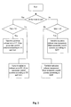
- Fig. 3 shows an alternative embodiment of a method of climate control according to the present invention.
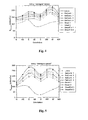
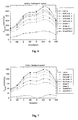
- Figs. 4-6 shows the total saved energy versus the orientation of the windows for different window alternatives with the method of climate control according to fig. 3, compared to an uncoated double glazed window, for three climate locations.
- Fig. 7 shows the same figure as in figure 4 but with twice the internal heat production.
- Fig. 8 shows the heating plus cooling demand per square meter floor area for the base case in three different climates.
- The basic idea behind the system of the present invention is that, if a room needs to be cooled, the transmission of heat radiation through the windows of the room is automatically kept to a minimum when the room is not in use. The expression "A room in use" is herein defined as a room in which at least one person is present. By this action the radiation induced heating of the room is kept to a minimum at times when no one uses the room, whereby the energy needed to cool the room is substantially reduced.
- In a basic embodiment, the climate control system of the invention operates independently of the other climate systems of a building, such as the cooling/heating system and the illumination system. With reference to fig 1, a first embodiment of a climate control system for a room comprises a
variable radiation reducer 12 arranged to variably control the intake of external heat radiation into the room, aclimate control unit 8 and ausage detection system 6. Theusage detection system 6 is coupled to theclimate control unit 8, and provides a "non-use signal" when the room is not in use and an "in-use signal" when the room is in use. The climate control unit (8), is arranged to respond to a "non-use signal" from the usage detection system (6), by setting the variable radiation reducer (12) in a non-transparent mode, whereby a substantial part of the heat radiation is prevented from entering the room. The climate control unit (8), is further arranged to respond to an "in-use signal" from the usage detection system (6), by setting the variable radiation reducer (12) in a transparent mode, whereby a normal daylight level is permitted to pass through the window. As a result of this, the climate control system of this embodiment always sets the variable radiation reducer 12 in a non-transparent mode when a room, or a part thereof, is not in use, and in transparent mode when the room or a part thereof is in use, irrespective of the temperature situation. - The accompanying method for controlling such a climate control system, is then:
- detecting, with the
usage detection system 6, if the room is in use or not, - in response to a "non-use signal" from the
usage detection system 6, controlling the variable radiation reducer 12 to be in a non-transparent mode, by means of theclimate control unit 8, whereby a substantial part of the heat radiation is prevented from entering the room, and - in response to a "in-use signal" from the
usage detection system 6, controlling the variable radiation reducer 12 to be in a transparent mode, by means of theclimate control unit 8, whereby a normal daylight level is permitted to pass through the window. - The usage detection system may e.g. be based on movement detection, radiation detection or the like. Alternatively, the usage detection system may be an active system, in which the persons using a room carry an identification device, which is registered by the detection system. If the detector registers no usage for a predetermined amount of time, the climate control system reduces transmission of heat radiation to a low value. Simple climate control comprising usage detection systems are known from US 4623969 and WO 8202608, which hereby are incorporated by reference. These systems basically describe how a control system for the present invention may be designed, but they lack a number of the core features of the invention.
- In more preferred embodiments the climate control system of the present invention, the heating/cooling system (the daylight control system), the ventilation system and the illumination system in a building, are integrated into a total climate control system. Such an integrated control system assures that a minimum of energy is needed to keep the desired climate and light level inside the building at all times. Furthermore, such a system is preferably arranged in such a manner that each room in the building can be independently controlled according to a local set of climate parameters. Examples of climate parameters to be set for each room are temperature, incoming daylight level and total light level. In some cases, different sections of a room may be independently controlled.
- For each room to be controlled, the control system registers internal parameters such as temperature, incoming daylight level, total light level and usage (as mentioned in detail above). Further, the climate control system may detect external parameters such as temperature, daylight intensity level, humidity. These parameters, together with geometric and physical information regarding the building, are used as input data in the control system.
- In a preferred embodiment of the present invention, which is shown in fig 1, the climate control system is comprised of
parameter control systems 2,indoor climate sensors 4 and ausage detection system 6, which all are coupled to aclimate control unit 8. Optionally, the climate control system further comprisesoutdoor climate sensors 10. - The
parameter control systems 2 comprise at least onevariable radiation reducer 12, a cooling/heating system 14, aventilation system 15 and anillumination system 16. - The
indoor climate sensors 4 comprise, in each room wherein the climate is to be controlled, at least one sensor for detection of a total light level 18 (TLM), at least one sensor for detection of an incoming daylight level 20 (IDM), and at least one sensor for detection of a temperature 22 (TM). The totallight level sensor 18 is arranged such that it registers the light level in the room, which is a sum of incoming daylight and light produced by theillumination system 16. The totallight level sensor 18 is preferably arranged in the vicinity of a point-of-use in the room, such that an appropriate light level is achieved where it is needed, e.g. at a writing-desk or the like. The incoming daylight sensor(s) 20 is arranged such that it registers the amount of daylight that enters the room through the window(s). Thetemperature sensor 22 is coupled to theclimate control unit 8, and it provides a "cool-signal" when the room should be cooled and a "heat-signal" when the room should be heated. Each room further comprises ausage detection system 6, for detecting if the room is being used or not. - The
outdoor climate sensors 10 comprise sensors for detection ofdaylight level 32,humidity 34, andtemperature 36. The detected levels from these detectors are then used by theclimate control unit 8 when controlling the indoor climate, but details regarding such control strategies lie outside the scope of this application and hence they are not further discussed herein. - The
climate control unit 8 comprises a microprocessor unit, which controls the indoor climate in accordance with the method described below. The desired indoor climate is defined by a set of predefinedlocal control parameters 24 and global control parameters 25 (GCP). Thelocal control parameters 24 comprise parameters defining a total light level 26 (TLC), window transmittance 28 (HT, LT) and temperature 30 (TC) that are local for a single room or a part of a room. Preferably, the user sets thelocal control parameters 24 using a dedicated control panel (not shown) in the room, such that maximum comfort is achieved. Alternatively the control panel may be substituted by a remote control or a software control panel running on a computer coupled to theclimate control unit 8. Theglobal control parameters 25 mainly concern regulation of the climate during long non-use periods, such as lowering/rising the temperature and turning off the ventilation system and the like, but such measures are well known in prior art and therefore not further discussed in this application. - The total
light level parameter 26 is a value that defines a desired light level at the position of the totallight level sensor 18, and theclimate control unit 8 is arranged to keep this level steady by adjusting theillumination system 16 and/or thevariable radiation reducer 12. - The
window transmittance parameters 28 preferably comprise a low-transmittance parameter (LT) defining the lowest level of incoming daylight that is accepted by the user, and a high-transmittance parameter (HT) defining the highest level of incoming daylight that is accepted by the user. These two parameters are essential as they allow the user of the room to avoid an unwanted excess or deficiency of daylight in the room, in situations when the climate control system from an energy minimization point of view strive towards such conditions. - The
climate control unit 8 registers the output signals from theindoor climate sensors 4, theusage detection system 6 and theoutdoor climate sensors 10, and uses these output signals to control theparameter control systems 2 according to thelocal control parameters 24 and theglobal control parameters 25 to achieve the desired indoor climate. - A method for controlling a system according to this embodiment will now be described with reference to fig. 2.
- detecting, with the
usage detection system 6, if the room is in use or not, - detecting with the
temperature sensor 22 if the room should be cooled or heated - in response to an "in-use signal" from the
usage detection system 6 and a "cool-signal" (TM > TC) from thetemperature sensor 22, controlling thevariable radiation reducer 12 to be in a low-transparent mode defined by the low-transmittance parameter 28 (LT), and otherparameter control systems local control parameters climate control unit 8, whereby at least a part of the heat radiation may be prevented from entering the room, - in response to a "non-use signal" from the
usage detection system 6 and a "cool-signal" (TM > TC) from thetemperature sensor 22, controlling thevariable radiation reducer 12 to be in a non-transparent mode, and otherparameter control systems climate control unit 8, whereby a substantial part of the heat radiation is prevented from entering the room, - in response to an "in-use signal" from the
usage detection system 6 and a "heat-signal" from thetemperature sensor 22, controlling thevariable radiation reducer 12 to be in a high-transparent mode defined by the high-transmittance parameter 28 (HT), and otherparameter control systems local control parameters climate control unit 8, whereby at least a part of the heat radiation is allowed to enter the room, and - in response to a "non-use signal" from the
usage detection system 6 and a "heat-signal" (TM < TC) from thetemperature sensor 22, controlling thevariable radiation reducer 12 to be in a transparent mode, and otherparameter control systems climate control unit 8, whereby a maximum of the heat radiation is allowed to enter the room. - As mentioned above the climate control system and method are further adapted to control the light-level, by controlling the
illumination system 16, the temperature and air quality by controlling the cooling/heating system 14 and theventilation system 15. But, as control strategies for such systems are well known in prior art, detailed control information for those are not given herein. - As the climate control system employs a
usage detection system 6, it could also be integrated with a security system in the building, whereby several new features could be provided. One possible feature could be that the variable radiation-reducers 12 and theillumination system 16 remain dark if unauthorized persons enter a room. - The climate control system is also suitable for integration into a larger control system, e.g. in the advanced control and information system of an "intelligent building".
- To further enhance the comfort characteristics of the system according to the invention, the system can employ predefined personal comfort profiles. In one embodiment the usage detection system may be adapted to recognize different users, and thus automatically change the desired climate in a room to the appropriate comfort profile as the user enters.
- A second possible enhancement is that the in-use comfort profile is preactivated somewhat before the user enters (or is expected to enter) the room, such that possible inconveniences due to initial poor climate are avoided. This might for instance be realized by user detection at the entrance of a building, and where the system knows which room the user normally occupies. But, as different users exhibit different habits such a system is preferably self-learning, whereby changes in habits are automatically detected and compensated for. In some particular situations the positive effects of pre-activation are more obvious than in others:
- Hotels have many rooms that are unoccupied during large parts of the day, and hence large energy savings are achieved by applying a system according to the invention. But it is of great importance that the climate comfort is high when a guest enters the room.
Therefore, pre-activation of the in-use comfort profile, for instance by registration in the lobby or in the elevators, is essential in this particular case. - School-buildings have certain rooms that are non-frequently used, but where subsequent use often can be predicted as the use is related to a schedule.
- The invention has been described using the term variable radiation-
reducer 12, as defined above, but as mechanical systems exhibit some drawbacks compared to smart windows, the use of smart windows is the preferred implementation. - A mechanical system may either be arranged on the outside, in between, or on the inside of the windows. If it is arranged on the outside, which from the heat rejecting point of view is the most beneficial, the system is further subjected to mechanical strains due to wind etc., whereby it can easily be damaged. Irrespective of where such a mechanical system is arranged the mechanical nature of the system makes it vulnerable, as it normally comprises a large number of parts and some parts may break or get worn out. Another drawback with the mechanical systems is that the radiation reducing elements normally comprise one or more non-transparent parts, which generate an unwanted pattern of silhouettes. As the transmittance for smart windows may be continuously varied from transparent to non-transparent, all such effects are avoided.
- However, as the
smart windows 12 that are available at present have switch-times (between non-transmittance and full-transmittance) of the order of milliseconds to tens of minutes, the daylight contribution to the light level in the room may remain low for a while after someone starts using the room. Therefore, the climate control system has to compensate for this lack of daylight by increasing the light intensity produced by theillumination system 16, and as thewindows 12 become more transparent, the light intensity from theillumination system 16 is gradually reduced. - To evaluate possible savings that may be achieved by the present invention, extensive simulations have been performed.
- Throughout the simulations a very simple physical description of an office module is used, in which different high performance static and variable windows are compared. Some features of the office module and the climates are also varied.
- As a building simulation tool the simple hourly dynamic model presented by Keller et al. (A universally valid strategy for low energy houses. Proc. World Renewable Energy Congress VI. 1, 377-382, Edited by, Sayigh A.A. M., Brighton, July, 2000) (see also: Burmeister and Keller, Climate surfaces: A quantitative building-specific representation of climates. Energy and Buildings, 28, 167-177, 1998.) is used with TRY (Test Reference Year) weather data as input. The anisotropic Hay and Davies (see for instance: Duffy and Beckman, Solar energy of thermal processes, 2 ed., Wiley, USA. 1991) model is used for the solar radiation on vertical surfaces and the angular dependence of the transmittance of the glazings is calculated according to Karlsson and Roos (Modelling the angular behaviour of the total solar energy transmittance of windows. Solar Energy 69, 321-329, 2000). All U-values are assumed to be constant.
- A "base-case" was defined as a commercial office module of a very simple "shoe box" form, described in table 1. The office module was assumed to have adiabatic surfaces in all orientations except for the front facing surface. The "free" internal heat was assumed to be 330W during office hours, which corresponds to about 1 person, one computer and energy efficient lighting, and 0W after working hours. Heating and cooling set points were different during working hours and non-working hours and the ventilation was reduced during non-working hours as described in table 1, wherein: GWAR denotes glazing to wall area ratio. Heating and cooling plant efficiency is set to unity. The base case window is uncoated and double-glazed.
Table 1. BASE CASE (south facing, no shading) Front wall U-value 0.3 W/m2K Glazing U-value 2.9 W/m2K Frame U-value 2.2 W/m2K GWAR 30 % Glazing g-value 76 % Time constant1 180 h Working hours (8-17) else "Free" internal heat 330 W 0 Heating set point 20 17 Cooling set point 25 28 Ventilation + infiltration 1.1 + 0.1 ach 1.1 *0.25 + 0.1 ach - Three different locations were chosen for the simulations: Stockholm (Sweden), Denver (USA) and Miami (USA), all having highly different annual average temperatures and annual solar radiation as illustrated in table 2, wherein TMY means Typical Meteorological Year and TRY means Test Reference Year.
Table 2 Location Annual average temperature (°C) Annual average solar radiation (kWh/m 2 yr, horizontal surface) Stockholm (TRY) Low (6.9) Low (920) Denver (TMY2) Low (9.9) High (1700) Miami (TMY2) High (24) High (1800) - A test set of glazings containing one uncoated, one low-e, four solar control and four smart windows as described in table 3 were used. Smart 1 and 2 are data from currently available smart windows, and
SmartFict Table 3 Identity Type g (%) U (W/m 2 K) Category Panes T vis (%) Clear Clear floatglass 76 2.9 4 2 82 Low-e Low-e 56 0.9 3.5 3 64 SolContr.1 Solar control 24 0.8 2.5 3 36 SolContr. 2 Solar control 27 1.2 2.5 2 42 SolContr. 3 Solar control 34 1 1.5 2 67 SolContr. 4 Solar control 18 1 1.5 2 32 Smart 1Smart (existing) 44/15 1.6 1 2+1 50/15 Smart 2Smart (existing) 36/12 1.1 1 2+1 50/15 SmartFict 1Smart (fictitious) 44/3 1 1 2 55/0 SmartFict 2Smart (fictitious) 56/3 1 1 2 65/0 - The flow chart shown in figure 3 shows an alternative, slightly simplified, embodiment of a method for climate control according to the present invention, which was employed throughout the simulations. This control system requires controllable HVAC (Heating, Ventilation, and Air Conditioning), lighting and switchable windows. Furthermore this would require temperature, light and occupancy sensors. In the following cases it was assumed that the occupant in the room was out of the
room 25%, randomly distributed, of the office hours. Lighting was set to full when the office was occupied and zero when unoccupied, and when the office was occupied, the transmittance through the windows was controlled linearly by the impinging radiation. - Figures 4-6 shows the total (heating plus cooling) saved energy versus the orientation of the windows for the different window alternatives with the intelligent HVAC/lighting/occupancy control system compared to an uncoated double glazed window for the three climate locations respectively. For comparison of best switchable window versus best static window see difference between "
Smartfict 2" and "Solcontr 1". In figure 4 it is illustrated that with the advanced control system in Stockholm the future smart windows can, just barely, outperform the best static alternatives and the present smart windows cannot. However, in the Denver climate (fig. 5) the saving was noticeably increased by the intelligent control system, figure 5. In this climate, the future smart windows illustrate savings of the order of about 50 kWh/m2yr and the best present smart window outperforms the best static by about 0-30 kWh/m2yr, depending on the orientation. Finally, for the Miami climate (fig. 6) the intelligent control system increased the saving to about 100 kWh/ m2yr and 50 kWh/m2yr for the future and the present smart window alternatives, respectively, and for south facing orientations and compared to the best static window (figure 6). Note that the y-axis in figures 4-6 represents saving compared to the base case windows and that the total energy demand of the office module is affected by the control system for all types of windows. - Figure 7 shows the same figure as in figure 4 but with twice the internal heat production. For comparison of best switchable window versus best static window see difference between "
Smartfict 2" and "Solcontr. 4". The saving caused by the smart window increased with increased internal heat load for the Stockholm climate. In this case the internal heat production was doubled to 660W, which would correspond to about two persons, two computers and inefficient lighting, and it is seen that the saving with the switchable window increased to of the order of 50 kWh/m2yr compared to the best solar control window. The saving also increased for the Denver climate (to about 75 kWh/m2yr) when the internal heat was increased but that illustration is left out here. - To summarise and compare, the different changes are plotted in figure 8 where each measure is added to the base case. More specifically figure 8 shows the heating plus cooling demand per square meter floor area for the base case in the three different climates. The leftmost bar gives the demand for the base case and the staples to the right gives the demand when changing to the best static window, plus controlled heat recovery, plus best smart window, plus occupancy control with 25% randomly distributed absence. Note that the energy in figure 8 is given per square meter floor area as opposed to the figures above were the saving is given per square meter glazed area. For all locations it is clearly important to choose the appropriate window (and/or shading) from the beginning. Controlled heat recovery of the exhaust air is of importance in heating dominated (cold) climates and of no importance in cooling dominated climates. The ability to vary the transmittance is of great importance in sunny climates, and the saving seems to be higher the warmer and the sunnier the climate is. Furthermore, figure 7 demonstrates that smart windows can be beneficial in less sunny climates if in an office with a high internal heat production.
- Occupancy control as described above increases the savings, especially in hot climates. The occupancy control also leads to electricity savings, not seen in figure 8, since the lighting and ventilation can be reduced when no one is present. Furthermore, when the office is occupied, automatically regulated light can reduce the electricity need, and if the smart window has a higher light transmittance in the transparent state than the window that it is compared with, this saving can be enhanced. In the Stockholm case (figure 8), the occupancy control leads to an increased heating need since "free" useful energy from persons and lighting were reduced during the 25% of time of absence. This is balanced by increased electricity savings from the reduced lighting and ventilation (not seen in figure 8). For the Miami case, the occupancy control leads to high cooling savings because of the reduced solar throughput and reduced internal energy from persons and lighting.
- There seems to be a "trade off" situation between natural lighting and cooling, i.e. higher fraction of natural light gives higher cooling demand and if the cooling demand is reduced by lower transmittance, less natural light is available. The static windows, on the other hand, may need additional shading to avoid glare, while the smart window can automatically reduce such problems.
- Approximate savings versus the best static window in an office module (as defined above) are of the order of: 0-50 kWh/ m2yr in a Stockholm-like climate, 25-75 kWh/ m2yr in a Denver-like climate, 50-150 kWh/ m2yr in a Miami-like climate (all given per square meter glazed area). These results will in a real situation also be affected by occupant behavior, but it is clear that the smart windows can have an equal or better energy performance than static windows and on top of this give an increased comfort with, for instance, automatic glare control. From figure 8 it can be further concluded that it is important to choose correct window (and/or shading). Switchable windows are beneficial in sunny climates and offices with high internal heat generation. Occupancy control saves cooling energy in the Denver-like, and even more in the Miami-like, climates. Furthermore, occupancy control, regulated lighting and ventilation also save electricity, which is not illustrated in this study.
- It should further be noted that the simulated 25% time of absence is a rough approximation, and for certain cases as discussed above the real time of absence might be considerably higher. However, even with this low approximation the simulations show that smart windows with occupancy control outperform state of the art static windows when it comes to energy, yet not taking in consideration the increased level of comfort.
- A number of embodiments have been described above. However, it is obvious that the design could be varied without deviating from the inventive idea of providing a more energy efficient climate control system comprising smart windows.
- Therefore the present invention should not be regarded as restricted to the above disclosed embodiments, but can be varied within the scope of the appended claims. For example, the climate control system can be implemented in all kinds of constructions, such as ships, land vehicles (cars, busses), airplanes etc., and the constructive modifications needed for such implementations pertains to the field of the person skilled in the art, requiring no inventive effort.
Claims (10)
- Climate control system comprising at least one variable radiation reducer (12) capable of variably reducing the transmission of heat radiation through a window, and a climate control unit (8) coupled to and adapted to control the variable radiation reducer (12),
characterized in that
the system further comprises a usage detection system (6) for detecting if the room is in use or not, the usage detection system (6) being coupled to the climate control unit (8), and providing a "non-use signal" when the room is not in use and an "in-use signal" when the room is in use,
the climate control unit (8) is arranged to set the variable radiation reducer (12) in a non-transparent mode, in response to a "non-use signal" from the usage detection system (6), whereby a substantial part of the heat radiation is prevented from entering the room, and in that
the climate control unit (8) is arranged to set the variable radiation reducer (12) in a transparent mode, in response to an "in-use signal" from the usage detection system (6), whereby a normal daylight level is permitted to pass through the window. - Climate control system according to claim 1, characterized in that the system further comprises climate sensors (4, 10) for detection of climate parameters such as, total light level (18), incoming daylight level (20) and temperature (22)
- Climate control system according to claim 1 or 2, characterized in that the climate control system further comprises a cooling/heating system (14), which is controlled by the climate control unit (8).
- Climate control system according to any of the claims 1 to 3, characterized in that the climate control system further comprises an illumination system (16), which is controlled by the climate control unit (8).
- Climate control system according to any of the claims 1 to 4, characterized in that the usage detection system (6) comprises a movement detector.
- Climate control system according to any of the claims 1 to 4, characterized in that the usage detection system (6) is arranged to register an identification device, carried by the user.
- Climate control system according to any of the claims 1 to 6, characterized in that the variable radiation reducer (12) is a smart window.
- Climate control system according to any of the claims 1 to 6, characterized in that the variable radiation reducer (12) is a mechanical shade.
- Method of climate control in a room, using a climate control system comprising at least one variable radiation reducer (12) capable of variably reducing the transmission of heat radiation through a window, and a climate control unit (8) coupled to and adapted to control the variable radiation reducer (12), which method comprises the steps of:detecting, with a usage detection system (6), if the room is in use or not, the usage detection system (6) being coupled to the climate control unit (8), and providing a "non-use signal" when the room is not in use and an "in-use signal" when the room is in use,in response to a "non-use signal" from the usage detection system (6), controlling the variable radiation reducer (12) to be in a non-transparent mode, by means of the climate control unit (8), whereby a substantial part of the heat radiation is prevented from entering the room, andin response to an "in-use signal" from the usage detection system (6), controlling the variable radiation reducer (12) to be in a transparent mode, by means of the climate control unit (8),whereby a normal daylight level is permitted to pass through the window.
- Method of climate control in a room, using a climate control system comprising at least one variable radiation reducer (12) capable of variably reducing the transmission of heat radiation through a window, and a climate control unit (8) coupled to and adapted to control the variable radiation reducer (12), which method comprises the steps of:detecting, with a usage detection system (6), if the room is in use or not, the usage detection system (6) being coupled to the climate control unit (8), and providing a "non-use signal" when the room is not in use and an "in-use signal" when the room is in use,detecting with a temperature sensor (22) if the room should be cooled or heated, the temperature sensor (22) being coupled to the climate control unit (8), and providing a "cool-signal" when the room should be cooled and a "heat-signal" when the room should be heated,in response to an "in-use signal" from the usage detection system (6) and a "cool-signal" from the temperature sensor (22), controlling the variable radiation reducer (12) to be in a low-transparent mode defined by a low-transmittance parameter (28), and other parameter control systems (2, 14, 16) in accordance with predefined local control parameters (24, 26, 30), by means of the climate control unit (8), whereby at least a part of the heat radiation is prevented from entering the room, unless the low-transmittance parameter (28) is set to a value that corresponds to full transmittance,in response to a "non-use signal" from the usage detection system (6) and a "cool-signal" from the temperature sensor (22), controlling the variable radiation reducer (12) to be in a non-transparent mode, and other parameter control systems (2, 14, 16) in accordance with predefined global control parameters (25), by means of the climate control unit (8), whereby a substantial part of the heat radiation is prevented from entering the room,in response to an "in-use signal" from the usage detection system (6) and a "heat-signal" from the temperature sensor (22), controlling the variable radiation reducer (12) to be in a high-transparent mode defined by the high-transmittance parameter (28), and other parameter control systems (2, 14, 16) in accordance with predefined local control parameters (24, 26, 30), by means of the climate control unit (8), whereby at least a part of the heat radiation is allowed to enter the room, andin response to a "non-use signal" from the usage detection system (6) and a "heat-signal" from the temperature sensor (22), controlling the variable radiation reducer (12) to be in a transparent mode, and other parameter control systems (2, 14, 16) in accordance with predefined global control parameters (25), by means of the climate control unit (8), whereby a maximum of the heat radiation is allowed to enter the room.
Applications Claiming Priority (3)
| Application Number | Priority Date | Filing Date | Title |
|---|---|---|---|
| SE0003112A SE0003112D0 (en) | 2000-09-04 | 2000-09-04 | Climate control system and method for controlling such |
| SE0003112 | 2000-09-04 | ||
| PCT/SE2001/001861 WO2002021231A1 (en) | 2000-09-04 | 2001-09-03 | Climate control system and a method for controlling such |
Publications (2)
| Publication Number | Publication Date |
|---|---|
| EP1336134A1 EP1336134A1 (en) | 2003-08-20 |
| EP1336134B1 true EP1336134B1 (en) | 2006-11-15 |
Family
ID=20280879
Family Applications (1)
| Application Number | Title | Priority Date | Filing Date |
|---|---|---|---|
| EP01965789A Expired - Lifetime EP1336134B1 (en) | 2000-09-04 | 2001-09-03 | Climate control system and a method for controlling such |
Country Status (7)
| Country | Link |
|---|---|
| US (1) | US6965813B2 (en) |
| EP (1) | EP1336134B1 (en) |
| AT (1) | ATE345523T1 (en) |
| AU (1) | AU2001286348A1 (en) |
| DE (1) | DE60124582T2 (en) |
| SE (1) | SE0003112D0 (en) |
| WO (1) | WO2002021231A1 (en) |
Families Citing this family (108)
| Publication number | Priority date | Publication date | Assignee | Title |
|---|---|---|---|---|
| US6567708B1 (en) * | 2000-07-25 | 2003-05-20 | Gentex Corporation | System to interconnect, link, and control variable transmission windows and variable transmission window constructions |
| AU2003257357A1 (en) * | 2002-09-13 | 2004-04-30 | Barix Ag | Method and device for controlling the thermal balance in buildings |
| US7450294B2 (en) * | 2004-03-12 | 2008-11-11 | Boeing Co | Multi-color electrochromic apparatus and methods |
| US8064120B2 (en) | 2004-03-12 | 2011-11-22 | The Boeing Company | Aircraft cabin services system including zone controllers for lighting control modules and dimmable windows |
| US20050200934A1 (en) * | 2004-03-12 | 2005-09-15 | The Boeing Company | Dimming control system for an array of electrochromic devices |
| US7610910B2 (en) * | 2004-03-25 | 2009-11-03 | Siemens Building Technologies, Inc. | Method and apparatus for controlling building component characteristics |
| US7412842B2 (en) | 2004-04-27 | 2008-08-19 | Emerson Climate Technologies, Inc. | Compressor diagnostic and protection system |
| WO2006023075A2 (en) | 2004-08-11 | 2006-03-02 | Lawrence Kates | Method and apparatus for monitoring refrigerant-cycle systems |
| US7424343B2 (en) | 2004-08-11 | 2008-09-09 | Lawrence Kates | Method and apparatus for load reduction in an electric power system |
| US7275377B2 (en) | 2004-08-11 | 2007-10-02 | Lawrence Kates | Method and apparatus for monitoring refrigerant-cycle systems |
| US20090204262A1 (en) * | 2004-09-28 | 2009-08-13 | Daikin Industries, Ltd. | Environmental control apparatus, environmental control system, environmental control method, and environmental control program |
| US7355161B2 (en) * | 2005-12-15 | 2008-04-08 | The Boeing Company | Systems and methods for controlling windows with variable light transmission |
| US8590325B2 (en) | 2006-07-19 | 2013-11-26 | Emerson Climate Technologies, Inc. | Protection and diagnostic module for a refrigeration system |
| US20080216494A1 (en) | 2006-09-07 | 2008-09-11 | Pham Hung M | Compressor data module |
| US7948189B2 (en) * | 2006-09-26 | 2011-05-24 | Siemens Industry, Inc. | Application of microsystems for lighting control |
| US7865252B2 (en) * | 2007-01-26 | 2011-01-04 | Autani Corporation | Upgradeable automation devices, systems, architectures, and methods |
| US7893890B2 (en) * | 2007-03-05 | 2011-02-22 | The Boeing Company | Electrically dimmable combiner optics for head-up display |
| JP4803532B2 (en) * | 2007-04-06 | 2011-10-26 | Necカシオモバイルコミュニケーションズ株式会社 | Electronic device and electronic device program |
| US20090037142A1 (en) | 2007-07-30 | 2009-02-05 | Lawrence Kates | Portable method and apparatus for monitoring refrigerant-cycle systems |
| US8160752B2 (en) | 2008-09-30 | 2012-04-17 | Zome Networks, Inc. | Managing energy usage |
| US9140728B2 (en) | 2007-11-02 | 2015-09-22 | Emerson Climate Technologies, Inc. | Compressor sensor module |
| EP2080648A1 (en) | 2008-01-21 | 2009-07-22 | Visiocorp Patents S.à.r.l. | Climate control system |
| US7761186B2 (en) * | 2008-01-28 | 2010-07-20 | Tlc Integration, Llc | Automated lighting and building control system |
| US8866343B2 (en) | 2009-07-30 | 2014-10-21 | Lutron Electronics Co., Inc. | Dynamic keypad for controlling energy-savings modes of a load control system |
| US9124130B2 (en) | 2009-07-30 | 2015-09-01 | Lutron Electronics Co., Inc. | Wall-mountable temperature control device for a load control system having an energy savings mode |
| US8901769B2 (en) * | 2009-07-30 | 2014-12-02 | Lutron Electronics Co., Inc. | Load control system having an energy savings mode |
| US8946924B2 (en) | 2009-07-30 | 2015-02-03 | Lutron Electronics Co., Inc. | Load control system that operates in an energy-savings mode when an electric vehicle charger is charging a vehicle |
| US9013059B2 (en) | 2009-07-30 | 2015-04-21 | Lutron Electronics Co., Inc. | Load control system having an energy savings mode |
| US8417388B2 (en) * | 2009-07-30 | 2013-04-09 | Lutron Electronics Co., Inc. | Load control system having an energy savings mode |
| US8571719B2 (en) | 2009-07-30 | 2013-10-29 | Lutron Electronics Co., Inc. | Load control system having an energy savings mode |
| US8975778B2 (en) | 2009-07-30 | 2015-03-10 | Lutron Electronics Co., Inc. | Load control system providing manual override of an energy savings mode |
| US20110066302A1 (en) * | 2009-09-16 | 2011-03-17 | Mcewan John Arthur | Intelligent energy-saving system and method |
| US10303035B2 (en) | 2009-12-22 | 2019-05-28 | View, Inc. | Self-contained EC IGU |
| US20210063836A1 (en) | 2017-04-26 | 2021-03-04 | View, Inc. | Building network |
| US10747082B2 (en) | 2009-12-22 | 2020-08-18 | View, Inc. | Onboard controller for multistate windows |
| US8213074B1 (en) | 2011-03-16 | 2012-07-03 | Soladigm, Inc. | Onboard controller for multistate windows |
| CA2828740C (en) | 2011-02-28 | 2016-07-05 | Emerson Electric Co. | Residential solutions hvac monitoring and diagnosis |
| US9645465B2 (en) | 2011-03-16 | 2017-05-09 | View, Inc. | Controlling transitions in optically switchable devices |
| US10989977B2 (en) | 2011-03-16 | 2021-04-27 | View, Inc. | Onboard controller for multistate windows |
| US11822202B2 (en) | 2011-03-16 | 2023-11-21 | View, Inc. | Controlling transitions in optically switchable devices |
| US11054792B2 (en) | 2012-04-13 | 2021-07-06 | View, Inc. | Monitoring sites containing switchable optical devices and controllers |
| US9454055B2 (en) | 2011-03-16 | 2016-09-27 | View, Inc. | Multipurpose controller for multistate windows |
| US9412290B2 (en) | 2013-06-28 | 2016-08-09 | View, Inc. | Controlling transitions in optically switchable devices |
| US11630367B2 (en) | 2011-03-16 | 2023-04-18 | View, Inc. | Driving thin film switchable optical devices |
| US9778532B2 (en) | 2011-03-16 | 2017-10-03 | View, Inc. | Controlling transitions in optically switchable devices |
| US9030725B2 (en) | 2012-04-17 | 2015-05-12 | View, Inc. | Driving thin film switchable optical devices |
| US8705162B2 (en) | 2012-04-17 | 2014-04-22 | View, Inc. | Controlling transitions in optically switchable devices |
| US10935865B2 (en) | 2011-03-16 | 2021-03-02 | View, Inc. | Driving thin film switchable optical devices |
| RU2598172C2 (en) * | 2011-04-21 | 2016-09-20 | Конинклейке Филипс Н.В. | Electric light and daylight control system with dual-mode light sensor |
| US9150132B2 (en) | 2011-06-13 | 2015-10-06 | Ford Global Technologies, Llc | Vehicle comfort system with efficient coordination of complementary thermal units |
| CN103987909B (en) | 2011-10-21 | 2017-03-22 | 唯景公司 | MITIGATING THERMAL SHOCK IN TINTABLE WINDOWs |
| IN2014CN04573A (en) * | 2011-12-07 | 2015-09-18 | Koninkl Philips Nv | |
| US8964338B2 (en) | 2012-01-11 | 2015-02-24 | Emerson Climate Technologies, Inc. | System and method for compressor motor protection |
| US11635666B2 (en) | 2012-03-13 | 2023-04-25 | View, Inc | Methods of controlling multi-zone tintable windows |
| US12578609B2 (en) | 2012-03-13 | 2026-03-17 | View Operating Corporation | Methods of controlling multi-zone tintable windows |
| US11950340B2 (en) | 2012-03-13 | 2024-04-02 | View, Inc. | Adjusting interior lighting based on dynamic glass tinting |
| US9367053B2 (en) * | 2012-03-27 | 2016-06-14 | Siemens Schweiz Ag | System and method for coordination of building automation system demand and shade control |
| US10503039B2 (en) | 2013-06-28 | 2019-12-10 | View, Inc. | Controlling transitions in optically switchable devices |
| US9638978B2 (en) | 2013-02-21 | 2017-05-02 | View, Inc. | Control method for tintable windows |
| US11674843B2 (en) | 2015-10-06 | 2023-06-13 | View, Inc. | Infrared cloud detector systems and methods |
| US12619118B2 (en) | 2012-04-13 | 2026-05-05 | View Operating Corporation | Controlling transitions in optically switchable devices |
| US10048561B2 (en) | 2013-02-21 | 2018-08-14 | View, Inc. | Control method for tintable windows |
| EP3223532B1 (en) | 2012-04-13 | 2019-10-09 | View, Inc. | Applications for controlling optically switchable devices |
| US11255120B2 (en) | 2012-05-25 | 2022-02-22 | View, Inc. | Tester and electrical connectors for insulated glass units |
| US20150234369A1 (en) * | 2012-09-21 | 2015-08-20 | Koninklijke Philips N.V. | Unified controller for integrated lighting, shading and thermostat control |
| US9310439B2 (en) | 2012-09-25 | 2016-04-12 | Emerson Climate Technologies, Inc. | Compressor having a control and diagnostic module |
| US11966142B2 (en) | 2013-02-21 | 2024-04-23 | View, Inc. | Control methods and systems using outside temperature as a driver for changing window tint states |
| US11719990B2 (en) | 2013-02-21 | 2023-08-08 | View, Inc. | Control method for tintable windows |
| US12422725B2 (en) | 2013-02-21 | 2025-09-23 | View Operating Corporation | Control methods and systems using outside temperature as a driver for changing window tint states |
| US11960190B2 (en) | 2013-02-21 | 2024-04-16 | View, Inc. | Control methods and systems using external 3D modeling and schedule-based computing |
| US12372846B2 (en) | 2013-02-21 | 2025-07-29 | View Operating Corporation | Control methods and systems using external 3D modeling and schedule-based computing |
| US9551504B2 (en) | 2013-03-15 | 2017-01-24 | Emerson Electric Co. | HVAC system remote monitoring and diagnosis |
| CA2904734C (en) | 2013-03-15 | 2018-01-02 | Emerson Electric Co. | Hvac system remote monitoring and diagnosis |
| US9803902B2 (en) | 2013-03-15 | 2017-10-31 | Emerson Climate Technologies, Inc. | System for refrigerant charge verification using two condenser coil temperatures |
| AU2014248049B2 (en) | 2013-04-05 | 2018-06-07 | Emerson Climate Technologies, Inc. | Heat-pump system with refrigerant charge diagnostics |
| US12353111B2 (en) | 2013-06-28 | 2025-07-08 | View Operating Corporation | Controlling transitions in optically switchable devices |
| US12061404B2 (en) | 2013-06-28 | 2024-08-13 | View, Inc. | Controlling transitions in optically switchable devices |
| US9885935B2 (en) | 2013-06-28 | 2018-02-06 | View, Inc. | Controlling transitions in optically switchable devices |
| US20150025659A1 (en) * | 2013-07-17 | 2015-01-22 | Google Inc. | Home Automation Network |
| US11868103B2 (en) | 2014-03-05 | 2024-01-09 | View, Inc. | Site monitoring system |
| KR102336168B1 (en) | 2014-03-05 | 2021-12-07 | 뷰, 인크. | Monitoring sites containing switchable optical devices and controllers |
| US11150616B2 (en) | 2014-03-05 | 2021-10-19 | View, Inc. | Site monitoring system |
| US11743071B2 (en) | 2018-05-02 | 2023-08-29 | View, Inc. | Sensing and communications unit for optically switchable window systems |
| US10481459B2 (en) | 2014-06-30 | 2019-11-19 | View, Inc. | Control methods and systems for networks of optically switchable windows during reduced power availability |
| CA2970300A1 (en) | 2014-12-08 | 2016-06-16 | View, Inc. | Multiple interacting systems at a site |
| US11740948B2 (en) | 2014-12-08 | 2023-08-29 | View, Inc. | Multiple interacting systems at a site |
| WO2016182592A1 (en) * | 2015-05-11 | 2016-11-17 | Siemens Industry, Inc. | Energy-efficient integrated lighting, daylighting, and hvac with electrochromic glass |
| TWI746446B (en) | 2015-07-07 | 2021-11-21 | 美商唯景公司 | Viewcontrol methods for tintable windows |
| US12366111B2 (en) | 2015-09-18 | 2025-07-22 | View Operating Corporation | Trunk line window controllers |
| US11384596B2 (en) | 2015-09-18 | 2022-07-12 | View, Inc. | Trunk line window controllers |
| US11255722B2 (en) | 2015-10-06 | 2022-02-22 | View, Inc. | Infrared cloud detector systems and methods |
| US20170223802A1 (en) * | 2016-02-03 | 2017-08-03 | Honeywell International Inc. | Camera-aided controller of illumination |
| US10372990B2 (en) | 2016-03-18 | 2019-08-06 | International Business Machines Corporation | System and method for identification of personal thermal comfort |
| EP4130865B1 (en) | 2016-04-29 | 2025-10-22 | View, Inc. | Calibration of eletrical parameters in optically switchable windows |
| WO2018102635A1 (en) | 2016-12-01 | 2018-06-07 | Carrier Corporation | Building management system |
| CN106502287A (en) * | 2016-12-26 | 2017-03-15 | 阴勃龙 | Building temperature control system and its temperature control mechanism, temp. control method |
| TW201907213A (en) | 2017-04-26 | 2019-02-16 | 美商唯景公司 | Colored window system computing platform |
| US11747696B2 (en) | 2017-04-26 | 2023-09-05 | View, Inc. | Tandem vision window and media display |
| US12603091B2 (en) | 2017-04-26 | 2026-04-14 | View Operating Corporation | Immersive collaboration of remote participants via media displays |
| US12147142B2 (en) | 2017-04-26 | 2024-11-19 | View, Inc. | Remote management of a facility |
| US10589723B1 (en) * | 2018-09-21 | 2020-03-17 | Ford Global Technologies, Llc | Imaging system |
| US10597002B1 (en) | 2018-09-21 | 2020-03-24 | Ford Global Technologies, Llc | Imaging system |
| JP7644501B2 (en) | 2019-05-09 | 2025-03-12 | ビュー オペレーティング コーポレーション | Antenna systems for controlled coverage within buildings |
| US11631493B2 (en) | 2020-05-27 | 2023-04-18 | View Operating Corporation | Systems and methods for managing building wellness |
| EP3977557A1 (en) | 2019-05-31 | 2022-04-06 | View, Inc. | Building antenna |
| TW202206925A (en) | 2020-03-26 | 2022-02-16 | 美商視野公司 | Access and messaging in a multi client network |
| TW202230116A (en) | 2020-12-11 | 2022-08-01 | 美商視野公司 | Component updates in a multi component network |
| DE102021201377A1 (en) * | 2021-02-15 | 2022-08-18 | Volkswagen Aktiengesellschaft | Method for initiating a defrosting process of a heat exchanger of a heat pump of a motor vehicle |
Family Cites Families (9)
| Publication number | Priority date | Publication date | Assignee | Title |
|---|---|---|---|---|
| WO1982002608A1 (en) * | 1981-01-20 | 1982-08-05 | Miles Terrance Allen | Control system for energy consuming installation |
| CA1171938A (en) * | 1983-01-07 | 1984-07-31 | David Bensoussan | Automatic heating and air conditioning temperature, as well as humidity controller, dependent on the occupation of and lighting in locals |
| DE3643690A1 (en) * | 1986-12-20 | 1988-07-07 | Dornier System Gmbh | CONTROLLABLE DISC |
| DE4023673A1 (en) * | 1990-07-26 | 1992-02-06 | Vedder Gmbh Geb | Control and regulation system for doors, windows, blinds - has sensors to measure temp., humidity, solar radiation and controls opening, closing and regulates heating, cooling, etc. |
| FR2678752B1 (en) * | 1991-07-03 | 1993-10-29 | Somfy | INSTALLATION FOR CONTROLLING THE ILLUMINATION LEVEL OF A PREMISES. |
| AU4137396A (en) * | 1994-10-27 | 1996-05-23 | Erez Yahalomi | Regulating systems |
| DE19622253A1 (en) * | 1996-02-29 | 1997-09-04 | Zumtobel Licht | Method and device for controlling a dimming device |
| US6039390A (en) * | 1996-08-20 | 2000-03-21 | Donnelly Corporation | Chromogenic window assembly construction and other chromogenic devices |
| US6119186A (en) * | 1997-05-30 | 2000-09-12 | Texas Instruments Incorporated | Computer system with environmental manager for detecting and responding to changing environmental conditions |
-
2000
- 2000-09-04 SE SE0003112A patent/SE0003112D0/en unknown
-
2001
- 2001-09-03 AU AU2001286348A patent/AU2001286348A1/en not_active Abandoned
- 2001-09-03 EP EP01965789A patent/EP1336134B1/en not_active Expired - Lifetime
- 2001-09-03 WO PCT/SE2001/001861 patent/WO2002021231A1/en not_active Ceased
- 2001-09-03 AT AT01965789T patent/ATE345523T1/en not_active IP Right Cessation
- 2001-09-03 DE DE60124582T patent/DE60124582T2/en not_active Expired - Lifetime
-
2003
- 2003-03-04 US US10/377,724 patent/US6965813B2/en not_active Expired - Lifetime
Also Published As
| Publication number | Publication date |
|---|---|
| US20030233172A1 (en) | 2003-12-18 |
| EP1336134A1 (en) | 2003-08-20 |
| US6965813B2 (en) | 2005-11-15 |
| AU2001286348A1 (en) | 2002-03-22 |
| DE60124582T2 (en) | 2007-09-20 |
| DE60124582D1 (en) | 2006-12-28 |
| SE0003112D0 (en) | 2000-09-04 |
| WO2002021231A1 (en) | 2002-03-14 |
| ATE345523T1 (en) | 2006-12-15 |
Similar Documents
| Publication | Publication Date | Title |
|---|---|---|
| US6965813B2 (en) | Climate control system and method for controlling such | |
| CN107850815B (en) | Control method for tintable windows | |
| Teixeira et al. | Assessment of the visual, thermal and energy performance of static vs thermochromic double-glazing under different European climates | |
| Pereira et al. | Thermal, luminous and energy performance of solar control films in single-glazed windows: Use of energy performance criteria to support decision making | |
| Singh et al. | Effect of internal woven roller shade and glazing on the energy and daylighting performances of an office building in the cold climate of Shillong | |
| Li et al. | Experimental and theoretical study on the effect of window films on building energy consumption | |
| US20220214592A1 (en) | Control method for tintable windows | |
| RU2658096C2 (en) | Controlling transitions in optically switchable devices | |
| US9850705B2 (en) | Energy efficient shading systems for windows | |
| Peng et al. | Comparative study on the overall energy performance between photovoltaic and Low-E insulated glass units | |
| Etzion et al. | Controlling the transmission of radiant energy through windows: a novel ventilated reversible glazing system | |
| Moretti et al. | Evaluation of energy, thermal, and daylighting performance of solar control films for a case study in moderate climate | |
| Karlsson | Control system and energy saving potential for switchable windows | |
| Riganti et al. | Energy saving potential of advanced dual-band electrochromic smart windows for office integration | |
| Inoue | Solar shading and daylighting by means of autonomous responsive dimming glass: practical application | |
| Ouahrani et al. | Selection of slat separation-to-width ratio of brise-soleil shading considering energy savings, CO2 emissions and visual comfort–a case study in Qatar | |
| Inoue et al. | Thermotropic glass with active dimming control for solar shading and daylighting | |
| Ohene et al. | Quantifying energy benefits from window improvement strategies for commercial buildings | |
| Abdel-Moneim et al. | Using smart materials in smart windows for energy efficiency of buildings | |
| Lee et al. | A pilot demonstration of electrochromic and thermochromic windows in the Denver Federal Center, Building 41, Denver, Colorado | |
| Rudolph et al. | Technologies for smart windows | |
| Beck et al. | Solar shading | |
| Alias et al. | Review on Applications of Smart Glass in Green Buildings | |
| US20260016729A1 (en) | Wireless Building Windows with Variable Light Transmission | |
| Selkowitz | Window performance and building energy use: Some technical options for increasing energy efficiency |
Legal Events
| Date | Code | Title | Description |
|---|---|---|---|
| PUAI | Public reference made under article 153(3) epc to a published international application that has entered the european phase |
Free format text: ORIGINAL CODE: 0009012 |
|
| 17P | Request for examination filed |
Effective date: 20030402 |
|
| AK | Designated contracting states |
Designated state(s): AT BE CH CY DE DK ES FI FR GB GR IE IT LI LU MC NL PT SE TR |
|
| AX | Request for extension of the european patent |
Extension state: AL LT LV MK RO SI |
|
| GRAP | Despatch of communication of intention to grant a patent |
Free format text: ORIGINAL CODE: EPIDOSNIGR1 |
|
| GRAS | Grant fee paid |
Free format text: ORIGINAL CODE: EPIDOSNIGR3 |
|
| GRAA | (expected) grant |
Free format text: ORIGINAL CODE: 0009210 |
|
| RAP1 | Party data changed (applicant data changed or rights of an application transferred) |
Owner name: CHROMOGENICS SWEDEN AB |
|
| AK | Designated contracting states |
Kind code of ref document: B1 Designated state(s): AT BE CH CY DE DK ES FI FR GB GR IE IT LI LU MC NL PT SE TR |
|
| PG25 | Lapsed in a contracting state [announced via postgrant information from national office to epo] |
Ref country code: IT Free format text: LAPSE BECAUSE OF FAILURE TO SUBMIT A TRANSLATION OF THE DESCRIPTION OR TO PAY THE FEE WITHIN THE PRESCRIBED TIME-LIMIT;WARNING: LAPSES OF ITALIAN PATENTS WITH EFFECTIVE DATE BEFORE 2007 MAY HAVE OCCURRED AT ANY TIME BEFORE 2007. THE CORRECT EFFECTIVE DATE MAY BE DIFFERENT FROM THE ONE RECORDED. Effective date: 20061115 Ref country code: NL Free format text: LAPSE BECAUSE OF FAILURE TO SUBMIT A TRANSLATION OF THE DESCRIPTION OR TO PAY THE FEE WITHIN THE PRESCRIBED TIME-LIMIT Effective date: 20061115 Ref country code: FI Free format text: LAPSE BECAUSE OF FAILURE TO SUBMIT A TRANSLATION OF THE DESCRIPTION OR TO PAY THE FEE WITHIN THE PRESCRIBED TIME-LIMIT Effective date: 20061115 Ref country code: AT Free format text: LAPSE BECAUSE OF FAILURE TO SUBMIT A TRANSLATION OF THE DESCRIPTION OR TO PAY THE FEE WITHIN THE PRESCRIBED TIME-LIMIT Effective date: 20061115 Ref country code: BE Free format text: LAPSE BECAUSE OF FAILURE TO SUBMIT A TRANSLATION OF THE DESCRIPTION OR TO PAY THE FEE WITHIN THE PRESCRIBED TIME-LIMIT Effective date: 20061115 |
|
| REG | Reference to a national code |
Ref country code: GB Ref legal event code: FG4D |
|
| REG | Reference to a national code |
Ref country code: CH Ref legal event code: EP |
|
| REF | Corresponds to: |
Ref document number: 60124582 Country of ref document: DE Date of ref document: 20061228 Kind code of ref document: P |
|
| REG | Reference to a national code |
Ref country code: IE Ref legal event code: FG4D |
|
| PG25 | Lapsed in a contracting state [announced via postgrant information from national office to epo] |
Ref country code: DK Free format text: LAPSE BECAUSE OF FAILURE TO SUBMIT A TRANSLATION OF THE DESCRIPTION OR TO PAY THE FEE WITHIN THE PRESCRIBED TIME-LIMIT Effective date: 20070215 Ref country code: SE Free format text: LAPSE BECAUSE OF FAILURE TO SUBMIT A TRANSLATION OF THE DESCRIPTION OR TO PAY THE FEE WITHIN THE PRESCRIBED TIME-LIMIT Effective date: 20070215 |
|
| PG25 | Lapsed in a contracting state [announced via postgrant information from national office to epo] |
Ref country code: ES Free format text: LAPSE BECAUSE OF FAILURE TO SUBMIT A TRANSLATION OF THE DESCRIPTION OR TO PAY THE FEE WITHIN THE PRESCRIBED TIME-LIMIT Effective date: 20070226 |
|
| REG | Reference to a national code |
Ref country code: CH Ref legal event code: NV Representative=s name: PATENTANWAELTE SCHAAD, BALASS, MENZL & PARTNER AG |
|
| PG25 | Lapsed in a contracting state [announced via postgrant information from national office to epo] |
Ref country code: PT Free format text: LAPSE BECAUSE OF FAILURE TO SUBMIT A TRANSLATION OF THE DESCRIPTION OR TO PAY THE FEE WITHIN THE PRESCRIBED TIME-LIMIT Effective date: 20070416 |
|
| NLV1 | Nl: lapsed or annulled due to failure to fulfill the requirements of art. 29p and 29m of the patents act | ||
| EN | Fr: translation not filed | ||
| EN | Fr: translation not filed | ||
| PLBE | No opposition filed within time limit |
Free format text: ORIGINAL CODE: 0009261 |
|
| STAA | Information on the status of an ep patent application or granted ep patent |
Free format text: STATUS: NO OPPOSITION FILED WITHIN TIME LIMIT |
|
| 26N | No opposition filed |
Effective date: 20070817 |
|
| PG25 | Lapsed in a contracting state [announced via postgrant information from national office to epo] |
Ref country code: GR Free format text: LAPSE BECAUSE OF FAILURE TO SUBMIT A TRANSLATION OF THE DESCRIPTION OR TO PAY THE FEE WITHIN THE PRESCRIBED TIME-LIMIT Effective date: 20070216 Ref country code: MC Free format text: LAPSE BECAUSE OF NON-PAYMENT OF DUE FEES Effective date: 20070930 Ref country code: FR Free format text: LAPSE BECAUSE OF FAILURE TO SUBMIT A TRANSLATION OF THE DESCRIPTION OR TO PAY THE FEE WITHIN THE PRESCRIBED TIME-LIMIT Effective date: 20070629 |
|
| PG25 | Lapsed in a contracting state [announced via postgrant information from national office to epo] |
Ref country code: IE Free format text: LAPSE BECAUSE OF NON-PAYMENT OF DUE FEES Effective date: 20070903 |
|
| PG25 | Lapsed in a contracting state [announced via postgrant information from national office to epo] |
Ref country code: FR Free format text: LAPSE BECAUSE OF FAILURE TO SUBMIT A TRANSLATION OF THE DESCRIPTION OR TO PAY THE FEE WITHIN THE PRESCRIBED TIME-LIMIT Effective date: 20061115 |
|
| PG25 | Lapsed in a contracting state [announced via postgrant information from national office to epo] |
Ref country code: LU Free format text: LAPSE BECAUSE OF NON-PAYMENT OF DUE FEES Effective date: 20070903 Ref country code: CY Free format text: LAPSE BECAUSE OF FAILURE TO SUBMIT A TRANSLATION OF THE DESCRIPTION OR TO PAY THE FEE WITHIN THE PRESCRIBED TIME-LIMIT Effective date: 20061115 |
|
| PG25 | Lapsed in a contracting state [announced via postgrant information from national office to epo] |
Ref country code: TR Free format text: LAPSE BECAUSE OF FAILURE TO SUBMIT A TRANSLATION OF THE DESCRIPTION OR TO PAY THE FEE WITHIN THE PRESCRIBED TIME-LIMIT Effective date: 20061115 |
|
| PGFP | Annual fee paid to national office [announced via postgrant information from national office to epo] |
Ref country code: CH Payment date: 20180924 Year of fee payment: 18 Ref country code: GB Payment date: 20180925 Year of fee payment: 18 |
|
| REG | Reference to a national code |
Ref country code: CH Ref legal event code: PL |
|
| PG25 | Lapsed in a contracting state [announced via postgrant information from national office to epo] |
Ref country code: LI Free format text: LAPSE BECAUSE OF NON-PAYMENT OF DUE FEES Effective date: 20190930 Ref country code: CH Free format text: LAPSE BECAUSE OF NON-PAYMENT OF DUE FEES Effective date: 20190930 |
|
| GBPC | Gb: european patent ceased through non-payment of renewal fee |
Effective date: 20190903 |
|
| PG25 | Lapsed in a contracting state [announced via postgrant information from national office to epo] |
Ref country code: GB Free format text: LAPSE BECAUSE OF NON-PAYMENT OF DUE FEES Effective date: 20190903 |
|
| PGFP | Annual fee paid to national office [announced via postgrant information from national office to epo] |
Ref country code: DE Payment date: 20201002 Year of fee payment: 20 |
|
| REG | Reference to a national code |
Ref country code: DE Ref legal event code: R071 Ref document number: 60124582 Country of ref document: DE |