EP1336113B1 - Method and apparatus for determining the state of charge of a lithium-ion battery - Google Patents
Method and apparatus for determining the state of charge of a lithium-ion battery Download PDFInfo
- Publication number
- EP1336113B1 EP1336113B1 EP01997705A EP01997705A EP1336113B1 EP 1336113 B1 EP1336113 B1 EP 1336113B1 EP 01997705 A EP01997705 A EP 01997705A EP 01997705 A EP01997705 A EP 01997705A EP 1336113 B1 EP1336113 B1 EP 1336113B1
- Authority
- EP
- European Patent Office
- Prior art keywords
- battery
- charge
- current
- ramp
- lithium
- Prior art date
- Legal status (The legal status is an assumption and is not a legal conclusion. Google has not performed a legal analysis and makes no representation as to the accuracy of the status listed.)
- Expired - Lifetime
Links
- HBBGRARXTFLTSG-UHFFFAOYSA-N Lithium ion Chemical compound [Li+] HBBGRARXTFLTSG-UHFFFAOYSA-N 0.000 title claims abstract description 35
- 229910001416 lithium ion Inorganic materials 0.000 title claims abstract description 35
- 238000000034 method Methods 0.000 title claims abstract description 31
- 238000007599 discharging Methods 0.000 abstract description 12
- 238000005259 measurement Methods 0.000 description 6
- 230000006641 stabilisation Effects 0.000 description 5
- 238000011105 stabilization Methods 0.000 description 5
- 230000003213 activating effect Effects 0.000 description 2
- 230000000903 blocking effect Effects 0.000 description 2
- 238000004364 calculation method Methods 0.000 description 2
- 238000010438 heat treatment Methods 0.000 description 2
- 238000012360 testing method Methods 0.000 description 2
- 238000012935 Averaging Methods 0.000 description 1
- WHXSMMKQMYFTQS-UHFFFAOYSA-N Lithium Chemical compound [Li] WHXSMMKQMYFTQS-UHFFFAOYSA-N 0.000 description 1
- 238000009529 body temperature measurement Methods 0.000 description 1
- 230000003750 conditioning effect Effects 0.000 description 1
- 230000007423 decrease Effects 0.000 description 1
- 238000002474 experimental method Methods 0.000 description 1
- 238000012886 linear function Methods 0.000 description 1
- 229910052744 lithium Inorganic materials 0.000 description 1
- 238000012544 monitoring process Methods 0.000 description 1
Images

Classifications
-
- G—PHYSICS
- G01—MEASURING; TESTING
- G01R—MEASURING ELECTRIC VARIABLES; MEASURING MAGNETIC VARIABLES
- G01R31/00—Arrangements for testing electric properties; Arrangements for locating electric faults; Arrangements for electrical testing characterised by what is being tested not provided for elsewhere
- G01R31/36—Arrangements for testing, measuring or monitoring the electrical condition of accumulators or electric batteries, e.g. capacity or state of charge [SoC]
- G01R31/367—Software therefor, e.g. for battery testing using modelling or look-up tables
-
- G—PHYSICS
- G01—MEASURING; TESTING
- G01R—MEASURING ELECTRIC VARIABLES; MEASURING MAGNETIC VARIABLES
- G01R19/00—Arrangements for measuring currents or voltages or for indicating presence or sign thereof
- G01R19/30—Measuring the maximum or the minimum value of current or voltage reached in a time interval
-
- G—PHYSICS
- G01—MEASURING; TESTING
- G01R—MEASURING ELECTRIC VARIABLES; MEASURING MAGNETIC VARIABLES
- G01R31/00—Arrangements for testing electric properties; Arrangements for locating electric faults; Arrangements for electrical testing characterised by what is being tested not provided for elsewhere
- G01R31/36—Arrangements for testing, measuring or monitoring the electrical condition of accumulators or electric batteries, e.g. capacity or state of charge [SoC]
- G01R31/3644—Constructional arrangements
- G01R31/3648—Constructional arrangements comprising digital calculation means, e.g. for performing an algorithm
-
- G—PHYSICS
- G01—MEASURING; TESTING
- G01R—MEASURING ELECTRIC VARIABLES; MEASURING MAGNETIC VARIABLES
- G01R31/00—Arrangements for testing electric properties; Arrangements for locating electric faults; Arrangements for electrical testing characterised by what is being tested not provided for elsewhere
- G01R31/36—Arrangements for testing, measuring or monitoring the electrical condition of accumulators or electric batteries, e.g. capacity or state of charge [SoC]
- G01R31/382—Arrangements for monitoring battery or accumulator variables, e.g. SoC
- G01R31/3842—Arrangements for monitoring battery or accumulator variables, e.g. SoC combining voltage and current measurements
-
- G—PHYSICS
- G01—MEASURING; TESTING
- G01R—MEASURING ELECTRIC VARIABLES; MEASURING MAGNETIC VARIABLES
- G01R31/00—Arrangements for testing electric properties; Arrangements for locating electric faults; Arrangements for electrical testing characterised by what is being tested not provided for elsewhere
- G01R31/50—Testing of electric apparatus, lines, cables or components for short-circuits, continuity, leakage current or incorrect line connections
- G01R31/52—Testing for short-circuits, leakage current or ground faults
-
- H—ELECTRICITY
- H01—ELECTRIC ELEMENTS
- H01M—PROCESSES OR MEANS, e.g. BATTERIES, FOR THE DIRECT CONVERSION OF CHEMICAL ENERGY INTO ELECTRICAL ENERGY
- H01M10/00—Secondary cells; Manufacture thereof
- H01M10/05—Accumulators with non-aqueous electrolyte
- H01M10/052—Li-accumulators
-
- H—ELECTRICITY
- H01—ELECTRIC ELEMENTS
- H01M—PROCESSES OR MEANS, e.g. BATTERIES, FOR THE DIRECT CONVERSION OF CHEMICAL ENERGY INTO ELECTRICAL ENERGY
- H01M10/00—Secondary cells; Manufacture thereof
- H01M10/42—Methods or arrangements for servicing or maintenance of secondary cells or secondary half-cells
- H01M10/48—Accumulators combined with arrangements for measuring, testing or indicating the condition of cells, e.g. the level or density of the electrolyte
Definitions
- the battery 100 is considered to be stabilized when the rate of change of the OCV is less than a threshold, for example 0.0001 volts/minute. Stabilization time for a lithium-ion battery can be about 30 minutes.
- a lithium-ion battery 100 of a known type, but with an unknown state of charge (SOC) is placed in a measurement circuit consisting of voltmeter 6 with both the battery charging relay 4 and the battery discharging relay 11 deactivated.
- the voltmeter 6 is connected through signal interface 2 to computer 1.
- a technician operating the computer 1 can input the battery type of battery 100 into the computer.
- the computer 1 will then execute an OCV correlation algorithm, for example a table look-up followed by linear interpolation, to correlate the open-circuit voltage (OCV) measured by the voltmeter with the state-of-charge for the type of battery 100 under test.
- Figure 2 shows a sample plot of open-circuit voltage vs. state of charge for a typical lithium ion battery.
- the electrical current, at which either 1) or 2), above occurs, is defined as the battery ramp-peak current (RPC).
- RPC battery ramp-peak current
Landscapes
- Physics & Mathematics (AREA)
- General Physics & Mathematics (AREA)
- Engineering & Computer Science (AREA)
- Manufacturing & Machinery (AREA)
- Chemical & Material Sciences (AREA)
- Chemical Kinetics & Catalysis (AREA)
- Electrochemistry (AREA)
- General Chemical & Material Sciences (AREA)
- Secondary Cells (AREA)
- Charge And Discharge Circuits For Batteries Or The Like (AREA)
Abstract
Description
- This invention relates to the charging of lithium-ion batteries and more specifically to the determination of the optimum charging currents for lithium ion batteries.
- Lithium-ion secondary batteries are quickly gaining favor due to their lightweight and high energy density. Before now, chargers were built to charge the battery under relatively low currents for long periods of time, so as to avoid battery heating and electrode damage. Alternately, a relatively high fixed current was used which was known to be in a safe current regime for a newly manufactured battery. As the battery ages, or if a different battery is placed on a given charger, the fixed current may exceed the safe current regime, at which time battery heating and electrode damage might occur.
- In order to save time in the charging of lithium-ion batteries and to still assure the safety of the charging technique, it is desirable to be able to determine an optimum charging current. Further, to improve the charging techniques it is desirable to be able to have knowledge of the state of charge (SOC) and capacity of the battery being charged. Priorly in the art, SOC and capacity were obtained by fully charging and discharging the battery in question and tracking the corresponding battery voltage vs. energy input/output. This charging and discharging of each battery to be charged again requires time but also uses energy.
- A need therefore exists for methods that can determine the optimum charging current for safely yet time-effectively charging a specific lithium-ion battery. There also exists the related need for determining the SOC of the battery as part of the determination of the optimum charging current determination without the need to charge and discharge the specific battery to be charged.
- We have found that the optimal charging current of a lithium-ion battery can be determined by performing a series of charging experiments utilizing varying initial charging currents, and by then recording cell voltage, cell temperature, and charging time. Specifically, we have found that the controlling variable in determining the optimum charging current is the state of charge (SOC) of the battery. The storage capacity of a battery is typically specified in Amp-Hours (Ah), where 1 Ah = 3600 coulombs, and the state of charge (SOC) of a battery is defined as the actual charge stored in a given battery capacity divided by the storage capacity of that battery.
- In accordance with one aspect of our invention, look-up tables or algorithms for each type of lithium-ion battery are prepared and stored in a computer or database. These look-up tables co-relate ramp-peak current vs. state of charge for each type of lithium-ion battery. An embodiment additionally includes open-circuit voltage vs. state of charge co-relations. Our invention includes both the method steps for creation of the look-up tables as well as the use of the look-up tables in determining the optimum charging current for a particular lithium-ion battery.
-
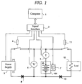
- Figure 1 shows a battery measurement circuit that is suitable for use with one illustrative embodiment of our invention.
- Figure 2 shows a sample plot of open-circuit voltage vs. state of charge for a typical lithium ion battery.
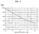
- Figure 3 shows a sample plot of ramp-peak current vs. state of charge for a typical lithium ion battery.
- One example of a method to determine the state of charge of a lithium-ion battery is based upon the measured open-circuit voltage for that battery.
- Referring to Figure 1, a lithium-
ion battery 100, of a known type, is shown in a measurementcircuit including voltmeter 6,ammeter 5, andthermocouple 7.Power supply 3 can be used to chargebattery 100 when battery-charging relay 4 is activated.Blocking diode 8 is used to limit the direction of current flow so that current flows only from thepower supply 3 to thebattery 100 during charging. Thebattery 100 can be discharged throughload 12 and blockingdiode 13 when battery-discharging relay 11 is activated. The circuit of Figure 1 can be used both to create look-up tables and to determine optimum charging current using those tables. - A
computer 1 receives voltage measurements fromvoltmeter 6 via asignal interface 2. Thecomputer 1 also receives battery temperature measurements fromthermocouple 7 and electrical current measurements fromammeter 5 via thesignal interface 2. Thecomputer 1 also controls the on-off states of thebattery charging relay 4 and the battery-discharging relay 11 via thesignal interface 2. - The
computer 1 can be, for example, a Gateway Pentium computer with a National Instrument data acquisition module installed therein. Thesignal interface 2 can be, for example, a National Instruments signal conditioning system with a digital to analog converter (DAC) module, an analog to digital converter module (ADC), a relay control module, and a thermocouple module installed therein. Thevoltmeter 6 can be, for example, included as a channel of the ADC module. The ammeter can be for example, comprised of a 50-amp/ 50-millivolt shunt and a channel of the ADC module. Thepower supply 3 can be, for example, a Hewlett-Packard model 6032A power supply. - The circuit shown in Figure 1 can be used to create a look-up table of open-circuit voltage (OCV) versus state of charge (SOC) for a particular type of lithium-ion battery as follows. First, the battery-
charging relay 4 is activated and the battery-discharging relay 11 is deactivated. Next, thebattery 100 is charged at an initial constant current (IO), for example 1 amp, by increasing the output voltage ofpower supply 3 while monitoring charging current into thebattery 100 usingammeter 5. Thebattery 100 is charged at this constant current, for example 1 amp until the voltage across the battery, as measured byvoltmeter 6 reaches a maximum permitted voltage (VMax). A battery manufacturer determines VMax based on safety considerations. A typical value of VMax for lithium-ion batteries is 4.2 volts per cell. For abattery 100 consisting of a multiple cells connected in series;
where N is the number of cells connected in series. When VMax is reached, charging is continued at this constant voltage, VMax, and the charging current is reduced (float charging). When the input current decreases to a certain point, for example to 1% of the initial constant current, the cells being charged are considered to be fully charged and at 100% SOC. The battery-charging relay 4 is then deactivated and thebattery 100 is allowed to stabilize, where battery stabilization is determined by the variation in the open-circuit voltage (OCV) of thebattery 100 as measured byvoltmeter 6. Thebattery 100 is considered to be stabilized when the rate of change of the OCV is less than a threshold, for example 0.0001 volts/minute. Stabilization time for a lithium-ion battery can be about 30 minutes. Thebattery 100 open-circuit voltage at 100% SOC (OCVSOC=100%) is recorded after thebattery 100 is stabilized. - Second, the
battery 100 is discharged at a predetermined discharge rate to a lower cutoff voltage (VMin) throughload 12 by activating the battery-discharging relay 11 and deactivating the battery-charging relay 4. The predetermined discharge rate can be selected as the value to completely discharge the battery, from 100% SOC to 0% SOC, in a time ranging from between 30 minutes to 5 hours. A battery manufacturer determines VMin based on safety considerations. A typical value of VMin for lithium-ion batteries is 3.0 volts per cell. For abattery 100 consisting of a multiple cells connected in series;
discharging relay 11 is then deactivated and thebattery 100 is allowed to stabilize, where battery stabilization is determined by the variation in the open-circuit voltage (OCV) of thebattery 100 as measured byvoltmeter 6. Thebattery 100 is considered to be stabilized when the rate of change of the OCV is less than a threshold, for example 0.001 to 0.005volts/minute. Stabilization time for a lithium-ion battery can be about 30 minutes. Thebattery 100 open-circuit voltage at 0% SOC (OCVSOC=0%) is recorded after thebattery 100 is stabilized. The capacity of thebattery 100 can be calculated by multiplying the discharge rate (amp) by the discharge time (hours). Note that battery capacity is typically specified in Amp-Hours (Ah), where 1 Ah equals 3600 coulombs. - Third, a predetermined number of coulombs, for example 10% of the battery capacity, is charged (input) into the
battery 100 frompower supply 3 at a predetermined charge rate by activating the battery-chargingrelay 4 and deactivating the battery-dischargingrelay 11. The predetermined charge rate can be selected as the value to completely charge thebattery 100, from 0% SOC to 100% SOC, in a time ranging from between 30 minutes to 5 hours. The battery-chargingrelay 4 is then deactivated and thebattery 100 is allowed to stabilize, where battery stabilization is determined by the variation in the open-circuit voltage (OCV) as previously described. Thebattery 100 open-circuit voltage at 10% SOC (OCVSOC=10%) is recorded after thebattery 100 is stabilized. This procedure is repeated and a set ofbattery 100 open-circuit voltages at various states of charge (e.g. 20%, 30%, ... 90%) are recorded. In another embodiment of our invention, the open-circuit voltage (OCV) is measured immediately at the conclusion of each charging interval and the measured value is extrapolated to obtain an estimate of the stabilized OCV. - Advantageously, additional tables of open-circuit voltage (OCV) versus state of charge (SOC) are prepared for various temperatures by performing the charge-discharge-charge procedure previously described at, for example, temperatures of -30 °C, 0 °C, +20 °C, and +50 °C.
- Referring again to Figure 1, a lithium-
ion battery 100 of a known type, but with an unknown state of charge (SOC) is placed in a measurement circuit consisting ofvoltmeter 6 with both thebattery charging relay 4 and thebattery discharging relay 11 deactivated. Thevoltmeter 6 is connected throughsignal interface 2 tocomputer 1. A technician operating thecomputer 1 can input the battery type ofbattery 100 into the computer. Thecomputer 1 will then execute an OCV correlation algorithm, for example a table look-up followed by linear interpolation, to correlate the open-circuit voltage (OCV) measured by the voltmeter with the state-of-charge for the type ofbattery 100 under test. Figure 2 shows a sample plot of open-circuit voltage vs. state of charge for a typical lithium ion battery. - In accordance with a further aspect, a
thermocouple 7 is attached to the side ofbattery 100 to provide battery temperature as an input tocomputer 1 viasignal interface 2. The OCV correlation algorithm will now use three inputs - battery type, open-circuit voltage, and battery temperature. For example, linear interpolation or a similar calculation can calculate state of charge (SOC) for abattery 100 at a temperature intermediate to temperature values associated with stored tables. - Patent document US 4725789 (Peled et al.) discloses a similar method for determining the state of charge of a lithium battery based on a look-up table with open-circuit voltage vs. state of charge.
- An embodiment of our invention is' a method to determine the state of charge of a lithium-ion battery based upon the measured ramp-peak current for that battery.
- The circuit shown in Figure 1 can also be used to create look-up table of ramp-peak current (RPC) versus state of charge (SOC) for a particular type of lithium-ion battery as follows. First, the
battery 100 is brought to a known state of charge (e.g. 10% SOC) by using, for example, the steps described inmethod 1 above. - Second, the battery-charging relay is activated and the battery-discharging relay is deactivated and a monotonically increasing current, for example an electrical current increasing from 0 amps to 20 amps in 60 seconds, is applied to the
battery 100 by thepower supply 3. The dependence of current increase with time, I = f(t), can be a linear function and is recorded bycomputer 1. As the input current is increased from 0 either 1) the input current causes the battery voltage to reach its maximum permitted voltage (VMax-ramp), as measured atvoltmeter 6, or 2) the input current equals a maximum current rating of thepower supply 3, or 3) a current limit chosen for the battery. The maximum permitted ramp voltage can be set at 100mV to 200mV above the maximum permitted charge voltage, since the duration of ramp energy input is limited. The electrical current, at which either 1) or 2), above occurs, is defined as the battery ramp-peak current (RPC). When thebattery 100 RPC is reached, the battery-chargingrelay 4 is deactivated and thebattery 100 ramp-peak current at 10% SOC (RPCSOC=10%) is recorded. This procedure is repeated and a set ofbattery 100 ramp-peak currents at various states of charge (e.g. 20%, 30%, ... 100%) are recorded. - Note there is a possibility for a battery of a known type that there may be several low states of charge (SOC), for example 10% SOC and 20% SOC, that correspond to a duplicate RPC value that is limited by the current rating of the
power supply 3. In this case, the rate of charge current can be increased, for example from 0 amps to 20 amps in 30 seconds, in order to create differing values of RPC corresponding to true state of charge ofbattery 100. - Further in accordance with our invention, additional tables of ramp-peak current (RPC) versus state of charge (SOC) may be prepared for various temperatures by performing the current ramping procedure previously described at, for example, temperatures of -30 °C, 0 °C, +20 °C, and +50 °C.
- Referring again to Figure 1, a lithium-
ion battery 100 of a known type, but with an unknown state of charge (SOC) is placed in a measurement circuit consisting ofpower supply 3,ammeter 5, andvoltmeter 6 and with both thebattery charging relay 4 and thebattery discharging relay 11 deactivated. Thepower supply 3,ammeter 5, andvoltmeter 6 are connected throughsignal interface 2 tocomputer 1. A technician operating thecomputer 1 can input the battery type ofbattery 100 into said computer. Thecomputer 1, will then execute a control-loop to activate the battery-chargingrelay 4 and monotonically increase the charging current, for example from 0 amps to 20 amps in 60 seconds, in accordance with a stored look-up table of the dependence of current increase with time, I = f(t). Thecomputer 1 increases thebattery 100 input current frompower supply 3 until it reaches RPC as described above and then thecomputer 1 deactivates the battery-chargingrelay 4. Thecomputer 1, will then execute an RPC correlation algorithm, for example a table look-up followed by linear interpolation, to correlate the ramp-peak current (RPC) as measured by theammeter 5 with the ramp-peak current for the type ofbattery 100 under test. If there is a case where thecomputer 100 correlation algorithm returns multiple possible ramp-peak current (RPC) values, then thecomputer 1 shall advise the user that the battery SOC is less than or equal to the highest possible state of charge (SOC) returned by the correlation algorithm. Figure 3 shows a plot of RPC vs. SOC for a typical lithium-ion battery. - As with the prior described method, the
thermocouple 7 attached to the side ofbattery 100 can provide battery temperature as an input tocomputer 1 viasignal interface 2. The RPC correlation algorithm will now use three inputs - battery type, open-circuit voltage, and battery temperature. For example, linear interpolation or a similar calculation can calculate state of charge (SOC) for abattery 100 at a temperature intermediate to temperature values associated with stored tables. - We have found it advantageous for the
computer 1 to perform a temperature compensated open-circuit voltage (OCV) correlation algorithm as described above, followed by a temperature compensated ramp-peak current (RPC) correlation algorithm, and combine, for example by averaging, to obtain a best estimate state of charge (SOC).
Claims (10)
- A method for creating a look-up table of ramp-current versus state of charge for a lithium-ion battery, said method comprising the steps of:(a) bringing the battery to a first present state of charge;(b) applying a monotonically increasing current to said battery from a power supply, where there is a dependence of current increase with time;(c) recording said dependence of increase with time;(d) increasing said monotonically increasing current to said battery until the current reaches a value defined as the ramp-peak current at the first present state of charge for said lithium-ion battery where either(i) a measured voltage for said battery reaches a predetermined maximum, or(ii) said monotonically increasing current equals a maximum current rating of the power supply;(e) recording said ramp-peak current at the present state of charge;(f) repeating said steps (a), (b), (c), (d), and (e) for additional states of charge, said recording step (e) recording said ramp-peak currents for the additional states of charge of said battery; and(g) generating the look-up table of ramp-peak current versus state of charge for the lithium-ion battery using the first and said additional states of charge for said battery.
- The method in accordance with claim 1 wherein said monotonically increasing current is an electrical current increasing from 0 amps to 20 amps in 60 seconds.
- The method in accordance with claim 1 wherein the first and additional present states of charge for said battery are 10%, 20%, 30%, 40%, 50%, 60%, 70%, 80%, 90%, and 100%.
- The method in accordance with claim1 further comprising the steps of
checking the look-up table for ramp-current versus state of charge for duplicate ramp-current values; and
repeating the steps of claim 1 for the states of charge with duplicate ramp-peak current values, except wherein the monotonically increasing current to said battery from said power supply has a different dependence of current with time. - The method in accordance with claim 1 wherein all the steps of claim 1 are repeated at a set of predetermined temperatures.
- The method in accordance with claim 5 wherein the set of predetermined temperatures consists of -30°C, 0°C, +20°C, and + 50°C.
- A method for determining the state of charge of a lithium-ion battery using a look-up table of ramp-peak current versus state of charge, said look-up table created by the method of any of the preceding claims, for that lithium-ion battery, and said method comprising the steps of:inputting into a computer the type of that lithium-ion battery;measuring a ramp-peak current for said battery,executing a ramp-peak current correlation algorithm based on inputs comprising:(i) the type of said battery inputted into said computer and(ii) the measured ramp-peak current for said battery; anddetermining the state of charge of the lithium-ion battery based on said ramp-peak current correlation algorithm.
- The method in accordance with claim 7 wherein said ramp-peak current correlation algorithm comprises a table-look up followed by linear interpolation.
- The method in accordance with claim 7 wherein said inputs to said ramp-peak current correlation algorithm further comprise measured battery temperature.
- The method in accordance with claim 7 further comprising measuring an open-circuit voltage for said battery and said inputs to said correlation algorithm further comprises the measured open circuit voltage for said battery.
Applications Claiming Priority (3)
| Application Number | Priority Date | Filing Date | Title |
|---|---|---|---|
| US09/721,003 US6586130B1 (en) | 2000-11-22 | 2000-11-22 | Method and apparatus for determining the state of charge of a lithium-ion battery |
| US721003 | 2000-11-22 | ||
| PCT/US2001/043735 WO2002042786A2 (en) | 2000-11-22 | 2001-11-19 | Method and apparatus for determining the state of charge of a lithium-ion battery |
Publications (2)
| Publication Number | Publication Date |
|---|---|
| EP1336113A2 EP1336113A2 (en) | 2003-08-20 |
| EP1336113B1 true EP1336113B1 (en) | 2006-05-10 |
Family
ID=24896114
Family Applications (1)
| Application Number | Title | Priority Date | Filing Date |
|---|---|---|---|
| EP01997705A Expired - Lifetime EP1336113B1 (en) | 2000-11-22 | 2001-11-19 | Method and apparatus for determining the state of charge of a lithium-ion battery |
Country Status (9)
| Country | Link |
|---|---|
| US (2) | US6586130B1 (en) |
| EP (1) | EP1336113B1 (en) |
| JP (1) | JP3893109B2 (en) |
| KR (2) | KR100830617B1 (en) |
| AT (1) | ATE326018T1 (en) |
| AU (1) | AU2002216709A1 (en) |
| CA (1) | CA2430208A1 (en) |
| DE (1) | DE60119565T2 (en) |
| WO (1) | WO2002042786A2 (en) |
Families Citing this family (62)
| Publication number | Priority date | Publication date | Assignee | Title |
|---|---|---|---|---|
| US6586130B1 (en) * | 2000-11-22 | 2003-07-01 | Honeywell International Inc. | Method and apparatus for determining the state of charge of a lithium-ion battery |
| SE0004772D0 (en) * | 2000-12-19 | 2000-12-19 | St Jude Medical | Method and apparatus for determining the depleted capacity of a battery |
| US20030137303A1 (en) * | 2002-01-24 | 2003-07-24 | Stefan Roepke | Device for determining charge condition of electric storage battery connected to a consumer |
| US7339347B2 (en) | 2003-08-11 | 2008-03-04 | Reserve Power Cell, Llc | Apparatus and method for reliably supplying electrical energy to an electrical system |
| US6984138B2 (en) * | 2003-10-24 | 2006-01-10 | International Components Corporation | Housing for cigarette lighter adapter or accessory adapter plug |
| US7876068B2 (en) * | 2003-10-24 | 2011-01-25 | International Components Corporation | Battery charge indicator |
| JP4547908B2 (en) * | 2003-12-25 | 2010-09-22 | 日産自動車株式会社 | Secondary battery input / output possible power estimation device |
| US7570024B2 (en) * | 2004-04-06 | 2009-08-04 | Cobasys, Llc | Battery state of charge voltage hysteresis estimator |
| JP4787241B2 (en) * | 2004-04-06 | 2011-10-05 | コバシス, エルエルシー | Battery charge state estimator |
| US7453238B2 (en) | 2004-04-06 | 2008-11-18 | Cobasys, Llc | State of charge tracking system for battery systems based on relaxation voltage |
| US7375497B2 (en) * | 2004-04-06 | 2008-05-20 | Cobasys, Llc | State of charge tracking system for battery systems |
| US7554295B2 (en) | 2004-04-06 | 2009-06-30 | Cobasys, Llc | Determination of IR-free voltage in hybrid vehicle applications |
| US8427109B2 (en) * | 2004-04-06 | 2013-04-23 | Chevron Technology Ventures Llc | Battery state of charge reset |
| US8878539B2 (en) | 2004-04-06 | 2014-11-04 | Robert Bosch Gmbh | State of charge tracking system for battery systems based on relaxation voltage |
| US7095211B2 (en) * | 2004-04-16 | 2006-08-22 | O2Micro International Limited | Battery gas gauge |
| US7248022B2 (en) * | 2004-06-04 | 2007-07-24 | Honeywell International, Inc. | Method and apparatus for determining the available energy of a lithium ion battery |
| US7209841B2 (en) | 2004-11-15 | 2007-04-24 | Cobasys, Llc | Maximum and minimum power limit calculator for batteries and battery subpacks |
| JP2006145285A (en) * | 2004-11-17 | 2006-06-08 | Ricoh Co Ltd | Battery level detection device |
| US7541781B2 (en) * | 2005-01-17 | 2009-06-02 | Cobasys, Llc | Method and apparatus for charging and discharging a rechargeable battery |
| KR20060098146A (en) * | 2005-03-09 | 2006-09-18 | 주식회사 엘지화학 | How to set initial value of remaining capacity of battery using open circuit voltage hysteresis according to temperature |
| US7688075B2 (en) * | 2005-04-20 | 2010-03-30 | Sion Power Corporation | Lithium sulfur rechargeable battery fuel gauge systems and methods |
| WO2007006121A1 (en) * | 2005-04-20 | 2007-01-18 | Mountain Power Inc. | Detecting the state-of-charge of a lithium ion battery in a hybrid electric vehicle |
| KR100759706B1 (en) * | 2005-05-11 | 2007-09-17 | 주식회사 엘지화학 | Method of estimating soc of battery for hybrid electric vehicle |
| JP4495116B2 (en) | 2005-06-30 | 2010-06-30 | エルジー・ケム・リミテッド | Battery remaining capacity estimation method and battery management system using the same |
| US8264203B2 (en) * | 2006-03-31 | 2012-09-11 | Valence Technology, Inc. | Monitoring state of charge of a battery |
| US7723958B2 (en) * | 2006-03-31 | 2010-05-25 | Valence Technology, Inc. | Battery charge indication methods, battery charge monitoring devices, rechargeable batteries, and articles of manufacture |
| US7576545B2 (en) | 2006-10-18 | 2009-08-18 | Honeywell International Inc. | Lithium-ion battery prognostic testing and process |
| KR100846712B1 (en) * | 2006-11-01 | 2008-07-16 | 삼성에스디아이 주식회사 | Battery Management System and Its Driving Method |
| WO2008095315A1 (en) * | 2007-02-09 | 2008-08-14 | Advanced Lithium Power Inc. | Battery management system |
| US7800344B2 (en) * | 2007-02-20 | 2010-09-21 | Delphi Technologies, Inc. | Method of determining the energy capacity of a battery |
| DE102007019987B4 (en) | 2007-04-27 | 2017-10-12 | Robert Bosch Gmbh | Determination of charge status of accumulators |
| DE102007034044B4 (en) * | 2007-07-20 | 2019-07-04 | Bayerische Motoren Werke Aktiengesellschaft | Method for determining a currently available amount of energy of an energy storage module |
| US8193761B1 (en) * | 2007-11-08 | 2012-06-05 | Honeywell International, Inc. | Hybrid power source |
| CN101388477B (en) * | 2008-09-28 | 2010-12-29 | 广州丰江电池新技术有限公司 | Fast charging method |
| US8354824B2 (en) * | 2009-05-08 | 2013-01-15 | Robert Bosch Gmbh | System and method for charging and discharging a Li-ion battery pack |
| FR2947637B1 (en) * | 2009-07-01 | 2012-03-23 | Commissariat Energie Atomique | METHOD FOR CALIBRATING AN ELECTROCHEMICAL BATTERY |
| JP5804523B2 (en) * | 2009-07-23 | 2015-11-04 | テキサス インスツルメンツ インコーポレイテッド | System and method for determining battery state of charge |
| TW201224485A (en) | 2010-12-02 | 2012-06-16 | Ind Tech Res Inst | State-of-charge estimation method and battery control unit |
| US9118191B2 (en) | 2011-08-29 | 2015-08-25 | Samsung Sdi Co., Ltd. | Cell balancing method, cell balancing device, and energy storage system including the cell balancing device |
| TWI420126B (en) * | 2011-09-27 | 2013-12-21 | Neotec Semiconductor Ltd | Device for battery capacity prediction and method for the same |
| DE102011087496A1 (en) * | 2011-11-30 | 2013-06-27 | H-Tech Ag | Method and device for charging rechargeable cells |
| FR2991076B1 (en) * | 2012-05-24 | 2015-03-13 | Commissariat Energie Atomique | METHOD FOR PROCESSING A SET OF QUADRUPLETS OF VALUES RELATING TO OPERATING POINTS OF AN ELECTROCHEMICAL ACCUMULATOR, METHOD FOR DETERMINING A STATE OF ENERGY FROM DATA DERIVED FROM THE PROCESSING PROCESS, RECORDING MEDIUM, COMPUTER PROGRAM AND DEVICE |
| JP6029251B2 (en) * | 2012-06-13 | 2016-11-24 | エルジー・ケム・リミテッド | Apparatus and method for estimating state of charge of secondary battery including mixed positive electrode material |
| JP2014102248A (en) * | 2012-10-24 | 2014-06-05 | Gs Yuasa Corp | Power storage state detection apparatus |
| CN103901347B (en) * | 2012-12-28 | 2016-11-23 | 华为终端有限公司 | A kind of method showing battery electric quantity and terminal |
| US9360530B2 (en) | 2013-08-19 | 2016-06-07 | Google Technology Holdings LLC | Method and system for energy storage capacity estimation of battery cells |
| JP6098496B2 (en) * | 2013-12-06 | 2017-03-22 | トヨタ自動車株式会社 | Power storage system |
| US9358899B2 (en) * | 2014-06-19 | 2016-06-07 | Ford Global Technologies, Llc | Method for revitalizing and increasing lithium ion battery capacity |
| WO2016054732A1 (en) * | 2014-10-06 | 2016-04-14 | Corvus Energy Ltd. | Method and system for estimating instantaneous state-of-charge of a lithium ion battery |
| KR102442187B1 (en) * | 2015-04-10 | 2022-09-07 | 삼성에스디아이 주식회사 | battery protection circuit |
| CN105609890B (en) * | 2015-12-31 | 2018-07-24 | 广州丰江电池新技术股份有限公司 | Non-constant voltage charging method for Li-ion battery with corrected compensation voltage |
| US10587130B2 (en) | 2016-11-04 | 2020-03-10 | International Business Machines Corporation | Automatically discharging a rechargeable battery |
| TWI625915B (en) * | 2016-11-18 | 2018-06-01 | Industrial Technology Research Institute | Smart charging method |
| US20180166888A1 (en) * | 2016-12-13 | 2018-06-14 | Bae Systems Controls Inc. | Managing Battery Charge Status To Provide Safe Operation For Electronic Devices |
| US10654337B2 (en) | 2016-12-21 | 2020-05-19 | Thermo King Corporation | Methods and systems for automatic control of an accessory powered by an auxiliary power unit |
| KR102206606B1 (en) | 2017-11-16 | 2021-01-21 | 주식회사 엘지화학 | Apparatus for estimating remain capacity |
| KR102441505B1 (en) * | 2017-12-11 | 2022-09-07 | 현대자동차주식회사 | How to charge a battery in an electric vehicle |
| US10933825B2 (en) | 2017-12-28 | 2021-03-02 | Thermo King Corporation | Operation of vehicle accessories based on predicted runtime of a primary system |
| KR102442632B1 (en) | 2018-02-09 | 2022-09-08 | 주식회사 엘지에너지솔루션 | Secondary battery state estimation apparatus and method |
| JP6751947B2 (en) * | 2018-11-27 | 2020-09-09 | 東洋システム株式会社 | Battery charge / discharge tester |
| CN111025168A (en) * | 2019-11-29 | 2020-04-17 | 淮南师范学院 | Battery health state monitoring device and battery state of charge intelligent estimation method |
| JP7690422B2 (en) * | 2022-03-28 | 2025-06-10 | 株式会社Aescジャパン | Battery management device, battery management method, and program |
Family Cites Families (10)
| Publication number | Priority date | Publication date | Assignee | Title |
|---|---|---|---|---|
| US4725784A (en) | 1983-09-16 | 1988-02-16 | Ramot University Authority For Applied Research & Industrial Development Ltd. | Method and apparatus for determining the state-of-charge of batteries particularly lithium batteries |
| US5633573A (en) * | 1994-11-10 | 1997-05-27 | Duracell, Inc. | Battery pack having a processor controlled battery operating system |
| FR2734061B1 (en) | 1995-05-12 | 1997-06-20 | Thomson Csf | METHOD FOR DETERMINING THE AVAILABLE CHARGE OF AN ACCUMULATOR BATTERY AT THE END OF DISCHARGE |
| FR2745088B1 (en) * | 1996-02-15 | 1998-04-10 | Oreal | METHOD FOR TESTING A SUBSTANCE POSSIBLE ACTIVE IN THE CAPILLARY DOMAIN |
| US6065182A (en) | 1996-06-07 | 2000-05-23 | Royal Appliance Mfg. Co. | Cordless wet mop and vacuum assembly |
| US5694023A (en) * | 1996-07-10 | 1997-12-02 | Advanced Charger Technology, Inc. | Control and termination of a battery charging process |
| JPH117984A (en) * | 1997-06-13 | 1999-01-12 | Sony Corp | Rechargeable battery capacity detection method |
| US6111389A (en) | 1998-06-18 | 2000-08-29 | Lucent Technologies Inc. | Rapidly charging a battery without overcharging |
| JP3669202B2 (en) * | 1999-04-20 | 2005-07-06 | 日産自動車株式会社 | Battery status monitoring device |
| US6586130B1 (en) * | 2000-11-22 | 2003-07-01 | Honeywell International Inc. | Method and apparatus for determining the state of charge of a lithium-ion battery |
-
2000
- 2000-11-22 US US09/721,003 patent/US6586130B1/en not_active Expired - Lifetime
-
2001
- 2001-11-19 JP JP2002545257A patent/JP3893109B2/en not_active Expired - Fee Related
- 2001-11-19 DE DE60119565T patent/DE60119565T2/en not_active Expired - Lifetime
- 2001-11-19 KR KR1020037006944A patent/KR100830617B1/en not_active Expired - Fee Related
- 2001-11-19 WO PCT/US2001/043735 patent/WO2002042786A2/en not_active Ceased
- 2001-11-19 CA CA002430208A patent/CA2430208A1/en not_active Abandoned
- 2001-11-19 AT AT01997705T patent/ATE326018T1/en not_active IP Right Cessation
- 2001-11-19 AU AU2002216709A patent/AU2002216709A1/en not_active Abandoned
- 2001-11-19 EP EP01997705A patent/EP1336113B1/en not_active Expired - Lifetime
- 2001-11-19 KR KR1020077030190A patent/KR100874727B1/en not_active Expired - Fee Related
-
2003
- 2003-01-23 US US10/349,847 patent/US6774636B2/en not_active Expired - Lifetime
Also Published As
| Publication number | Publication date |
|---|---|
| KR100830617B1 (en) | 2008-05-20 |
| ATE326018T1 (en) | 2006-06-15 |
| KR100874727B1 (en) | 2008-12-19 |
| US20030112011A1 (en) | 2003-06-19 |
| DE60119565D1 (en) | 2006-06-14 |
| WO2002042786A2 (en) | 2002-05-30 |
| KR20080009234A (en) | 2008-01-25 |
| CA2430208A1 (en) | 2002-05-30 |
| JP3893109B2 (en) | 2007-03-14 |
| US6586130B1 (en) | 2003-07-01 |
| JP2004515195A (en) | 2004-05-20 |
| KR20030048480A (en) | 2003-06-19 |
| US6774636B2 (en) | 2004-08-10 |
| WO2002042786A3 (en) | 2002-10-24 |
| DE60119565T2 (en) | 2007-01-25 |
| EP1336113A2 (en) | 2003-08-20 |
| AU2002216709A1 (en) | 2002-06-03 |
Similar Documents
| Publication | Publication Date | Title |
|---|---|---|
| EP1336113B1 (en) | Method and apparatus for determining the state of charge of a lithium-ion battery | |
| Xiong et al. | Evaluation on state of charge estimation of batteries with adaptive extended Kalman filter by experiment approach | |
| Farmann et al. | A study on the dependency of the open-circuit voltage on temperature and actual aging state of lithium-ion batteries | |
| Roscher et al. | Reliable state estimation of multicell lithium-ion battery systems | |
| Hussein et al. | An overview of generic battery models | |
| US7456612B2 (en) | Method for estimating polarization voltage of secondary cell, method and device for estimating remaining capacity of secondary cell, battery pack system, and vehicle | |
| US7355411B2 (en) | Method and apparatus for estimating state of charge of secondary battery | |
| US7688075B2 (en) | Lithium sulfur rechargeable battery fuel gauge systems and methods | |
| US8093866B2 (en) | Method for managing charging of a rechargeable battery | |
| US7728598B2 (en) | Method and apparatus for estimating the charge/discharge electricity amount of secondary batteries | |
| EP2660615B1 (en) | Battery degradation level detection method | |
| US9429628B2 (en) | Application independent map-based cycle life testing of battery cells | |
| JP2004530882A (en) | Method and apparatus for estimating the available energy of a battery | |
| Liu et al. | Effects of depth-of-discharge, ambient temperature, and aging on the internal resistance of lithium-ion battery cell | |
| Pillai et al. | An improved approach to estimate the internal resistance of a battery during the HPPC test | |
| US7248022B2 (en) | Method and apparatus for determining the available energy of a lithium ion battery | |
| Husnayain | Profile of 12-v voltage-regulated lead-acid battery | |
| Kojima et al. | Development of Li-Ion Battery Emulator focusing on Transient Responses using Bipolar Amplifier | |
| Shh et al. | PNGV battery test manual | |
| Desai | Lithium-Ion Battery Aging Study Through Novel Approaches for State of Health Estimation | |
| CN120352792A (en) | Battery SOH estimation method | |
| Motloch et al. | PNGV Battery Testing Procedures and Analytical Methodologies for Hybrid Electric Vehicles | |
| Corp et al. | Peak-Power Characteristics of Improved Electric-Vehicle Batteries | |
| Motloch et al. | PNGV Battery Performance Testing and Analyses |
Legal Events
| Date | Code | Title | Description |
|---|---|---|---|
| PUAI | Public reference made under article 153(3) epc to a published international application that has entered the european phase |
Free format text: ORIGINAL CODE: 0009012 |
|
| 17P | Request for examination filed |
Effective date: 20030529 |
|
| AK | Designated contracting states |
Designated state(s): AT BE CH CY DE DK ES FI FR GB GR IE IT LI LU MC NL PT SE TR |
|
| AX | Request for extension of the european patent |
Extension state: AL LT LV MK RO SI |
|
| GRAP | Despatch of communication of intention to grant a patent |
Free format text: ORIGINAL CODE: EPIDOSNIGR1 |
|
| GRAS | Grant fee paid |
Free format text: ORIGINAL CODE: EPIDOSNIGR3 |
|
| GRAA | (expected) grant |
Free format text: ORIGINAL CODE: 0009210 |
|
| AK | Designated contracting states |
Kind code of ref document: B1 Designated state(s): AT BE CH CY DE DK ES FI FR GB GR IE IT LI LU MC NL PT SE TR |
|
| PG25 | Lapsed in a contracting state [announced via postgrant information from national office to epo] |
Ref country code: IT Free format text: LAPSE BECAUSE OF FAILURE TO SUBMIT A TRANSLATION OF THE DESCRIPTION OR TO PAY THE FEE WITHIN THE PRE;WARNING: LAPSES OF ITALIAN PATENTS WITH EFFECTIVE DATE BEFORE 2007 MAY HAVE OCCURRED AT ANY TIME BEFORE 2007. THE CORRECT EFFECTIVE DATE MAY BE DIFFERENT FROM THE ONE RECORDED.SCRIBED TIME-LIMIT Effective date: 20060510 Ref country code: NL Free format text: LAPSE BECAUSE OF FAILURE TO SUBMIT A TRANSLATION OF THE DESCRIPTION OR TO PAY THE FEE WITHIN THE PRESCRIBED TIME-LIMIT Effective date: 20060510 Ref country code: CH Free format text: LAPSE BECAUSE OF FAILURE TO SUBMIT A TRANSLATION OF THE DESCRIPTION OR TO PAY THE FEE WITHIN THE PRESCRIBED TIME-LIMIT Effective date: 20060510 Ref country code: BE Free format text: LAPSE BECAUSE OF FAILURE TO SUBMIT A TRANSLATION OF THE DESCRIPTION OR TO PAY THE FEE WITHIN THE PRESCRIBED TIME-LIMIT Effective date: 20060510 Ref country code: LI Free format text: LAPSE BECAUSE OF FAILURE TO SUBMIT A TRANSLATION OF THE DESCRIPTION OR TO PAY THE FEE WITHIN THE PRESCRIBED TIME-LIMIT Effective date: 20060510 Ref country code: FI Free format text: LAPSE BECAUSE OF FAILURE TO SUBMIT A TRANSLATION OF THE DESCRIPTION OR TO PAY THE FEE WITHIN THE PRESCRIBED TIME-LIMIT Effective date: 20060510 Ref country code: AT Free format text: LAPSE BECAUSE OF FAILURE TO SUBMIT A TRANSLATION OF THE DESCRIPTION OR TO PAY THE FEE WITHIN THE PRESCRIBED TIME-LIMIT Effective date: 20060510 |
|
| REG | Reference to a national code |
Ref country code: GB Ref legal event code: FG4D |
|
| REG | Reference to a national code |
Ref country code: CH Ref legal event code: EP |
|
| REF | Corresponds to: |
Ref document number: 60119565 Country of ref document: DE Date of ref document: 20060614 Kind code of ref document: P |
|
| REG | Reference to a national code |
Ref country code: IE Ref legal event code: FG4D |
|
| PG25 | Lapsed in a contracting state [announced via postgrant information from national office to epo] |
Ref country code: DK Free format text: LAPSE BECAUSE OF FAILURE TO SUBMIT A TRANSLATION OF THE DESCRIPTION OR TO PAY THE FEE WITHIN THE PRESCRIBED TIME-LIMIT Effective date: 20060810 Ref country code: SE Free format text: LAPSE BECAUSE OF FAILURE TO SUBMIT A TRANSLATION OF THE DESCRIPTION OR TO PAY THE FEE WITHIN THE PRESCRIBED TIME-LIMIT Effective date: 20060810 |
|
| PG25 | Lapsed in a contracting state [announced via postgrant information from national office to epo] |
Ref country code: ES Free format text: LAPSE BECAUSE OF FAILURE TO SUBMIT A TRANSLATION OF THE DESCRIPTION OR TO PAY THE FEE WITHIN THE PRESCRIBED TIME-LIMIT Effective date: 20060821 |
|
| PG25 | Lapsed in a contracting state [announced via postgrant information from national office to epo] |
Ref country code: PT Free format text: LAPSE BECAUSE OF FAILURE TO SUBMIT A TRANSLATION OF THE DESCRIPTION OR TO PAY THE FEE WITHIN THE PRESCRIBED TIME-LIMIT Effective date: 20061010 |
|
| NLV1 | Nl: lapsed or annulled due to failure to fulfill the requirements of art. 29p and 29m of the patents act | ||
| REG | Reference to a national code |
Ref country code: CH Ref legal event code: PL |
|
| ET | Fr: translation filed | ||
| PG25 | Lapsed in a contracting state [announced via postgrant information from national office to epo] |
Ref country code: IE Free format text: LAPSE BECAUSE OF NON-PAYMENT OF DUE FEES Effective date: 20061120 |
|
| PG25 | Lapsed in a contracting state [announced via postgrant information from national office to epo] |
Ref country code: MC Free format text: LAPSE BECAUSE OF NON-PAYMENT OF DUE FEES Effective date: 20061130 |
|
| PLBE | No opposition filed within time limit |
Free format text: ORIGINAL CODE: 0009261 |
|
| STAA | Information on the status of an ep patent application or granted ep patent |
Free format text: STATUS: NO OPPOSITION FILED WITHIN TIME LIMIT |
|
| 26N | No opposition filed |
Effective date: 20070213 |
|
| PG25 | Lapsed in a contracting state [announced via postgrant information from national office to epo] |
Ref country code: GR Free format text: LAPSE BECAUSE OF FAILURE TO SUBMIT A TRANSLATION OF THE DESCRIPTION OR TO PAY THE FEE WITHIN THE PRESCRIBED TIME-LIMIT Effective date: 20060811 |
|
| PG25 | Lapsed in a contracting state [announced via postgrant information from national office to epo] |
Ref country code: TR Free format text: LAPSE BECAUSE OF FAILURE TO SUBMIT A TRANSLATION OF THE DESCRIPTION OR TO PAY THE FEE WITHIN THE PRESCRIBED TIME-LIMIT Effective date: 20060510 Ref country code: LU Free format text: LAPSE BECAUSE OF NON-PAYMENT OF DUE FEES Effective date: 20061119 |
|
| PG25 | Lapsed in a contracting state [announced via postgrant information from national office to epo] |
Ref country code: CY Free format text: LAPSE BECAUSE OF FAILURE TO SUBMIT A TRANSLATION OF THE DESCRIPTION OR TO PAY THE FEE WITHIN THE PRESCRIBED TIME-LIMIT Effective date: 20060510 |
|
| REG | Reference to a national code |
Ref country code: FR Ref legal event code: PLFP Year of fee payment: 15 |
|
| PGFP | Annual fee paid to national office [announced via postgrant information from national office to epo] |
Ref country code: GB Payment date: 20151027 Year of fee payment: 15 Ref country code: DE Payment date: 20151130 Year of fee payment: 15 |
|
| PGFP | Annual fee paid to national office [announced via postgrant information from national office to epo] |
Ref country code: FR Payment date: 20151027 Year of fee payment: 15 |
|
| REG | Reference to a national code |
Ref country code: DE Ref legal event code: R119 Ref document number: 60119565 Country of ref document: DE |
|
| GBPC | Gb: european patent ceased through non-payment of renewal fee |
Effective date: 20161119 |
|
| REG | Reference to a national code |
Ref country code: FR Ref legal event code: ST Effective date: 20170731 |
|
| PG25 | Lapsed in a contracting state [announced via postgrant information from national office to epo] |
Ref country code: FR Free format text: LAPSE BECAUSE OF NON-PAYMENT OF DUE FEES Effective date: 20161130 |
|
| PG25 | Lapsed in a contracting state [announced via postgrant information from national office to epo] |
Ref country code: DE Free format text: LAPSE BECAUSE OF NON-PAYMENT OF DUE FEES Effective date: 20170601 Ref country code: GB Free format text: LAPSE BECAUSE OF NON-PAYMENT OF DUE FEES Effective date: 20161119 |
|
| P01 | Opt-out of the competence of the unified patent court (upc) registered |
Effective date: 20230525 |