EP1335212A2 - HF-Empfangsspulenanordnung für einen normalleitenden NMR-Resonator mit makroskopisch homogener Verteilung des leitenden Materials - Google Patents
HF-Empfangsspulenanordnung für einen normalleitenden NMR-Resonator mit makroskopisch homogener Verteilung des leitenden Materials Download PDFInfo
- Publication number
- EP1335212A2 EP1335212A2 EP03002283A EP03002283A EP1335212A2 EP 1335212 A2 EP1335212 A2 EP 1335212A2 EP 03002283 A EP03002283 A EP 03002283A EP 03002283 A EP03002283 A EP 03002283A EP 1335212 A2 EP1335212 A2 EP 1335212A2
- Authority
- EP
- European Patent Office
- Prior art keywords
- structures
- resonator
- conductor
- receiver coil
- compensation
- Prior art date
- Legal status (The legal status is an assumption and is not a legal conclusion. Google has not performed a legal analysis and makes no representation as to the accuracy of the status listed.)
- Granted
Links
Images





Classifications
-
- G—PHYSICS
- G01—MEASURING; TESTING
- G01R—MEASURING ELECTRIC VARIABLES; MEASURING MAGNETIC VARIABLES
- G01R33/00—Arrangements or instruments for measuring magnetic variables
- G01R33/20—Arrangements or instruments for measuring magnetic variables involving magnetic resonance
- G01R33/28—Details of apparatus provided for in groups G01R33/44 - G01R33/64
- G01R33/32—Excitation or detection systems, e.g. using radio frequency signals
- G01R33/34—Constructional details, e.g. resonators, specially adapted to MR
- G01R33/34046—Volume type coils, e.g. bird-cage coils; Quadrature bird-cage coils; Circularly polarised coils
-
- G—PHYSICS
- G01—MEASURING; TESTING
- G01R—MEASURING ELECTRIC VARIABLES; MEASURING MAGNETIC VARIABLES
- G01R33/00—Arrangements or instruments for measuring magnetic variables
- G01R33/20—Arrangements or instruments for measuring magnetic variables involving magnetic resonance
- G01R33/28—Details of apparatus provided for in groups G01R33/44 - G01R33/64
- G01R33/32—Excitation or detection systems, e.g. using radio frequency signals
- G01R33/34—Constructional details, e.g. resonators, specially adapted to MR
- G01R33/34092—RF coils specially adapted for NMR spectrometers
Definitions
- and z +
- normally conducting, inductively and in some cases also capacitively acting conductor structures of the RF resonator are arranged substantially on a z-direction translation-invariant ( z-invariant) surface in the radial (x, y) distance perpendicular to the z-axis.
- the present invention relates to the field of high resolution Nuclear magnetic resonance (NMR), in particular the design of normal conducting Resonators for receiving the NMR signal from the NMR sample.
- NMR Nuclear magnetic resonance
- the magnetic susceptibility i. the dia- or paramagnetic Properties of the conductor because these are the homogeneity of the static Magnetic field in the measurement volume and thus the resolution of the NMR spectrum can deteriorate severely.
- the ladder generally made of several material components with built up of different dia- and paramagnetic properties, and the percentage mass fraction of the individual material components chosen so that the total susceptibility of the conductor as accurately as possible Zero.
- Object of the present invention is to provide a new type of normal-conducting
- NMR resonators in which additional conductor structures be added as well as possible from the actual RF resonator are decoupled, and the disturbing, caused compensate as much as possible by the susceptibility of the conductor should.
- the smallest occurring distance between the test sample and the compensation arrangement means that the compensation arrangement comprises further conductor structures, which are RF decoupled from the RF resonator to a large extent, that the conductor structures of the compensation arrangement and the RF resonator in turn from individual , Leitleiter structures containing surface portions ( "Z-structures”) are composed, which lie in the z-invariant surface, each extend over the entire length in the z-direction of the conductor structures of the compensation arrangement and the RF resonator, and their conductor structures so are arranged that in a suitable
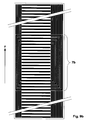
- FIG. 9b shows an arrangement constructed according to this principle, wherein the RF resonator is hatched and the additional conductor parts, which merely serve to homogenize the B 0 field in the active measuring range, are shown in black.
- this division is based only on the number the identical surface elements, which only by their z-position distinguish, i. lie on strips that are parallel to the z-axis are oriented. This number should be greater than 20, advantageously be greater than 50.
- An embodiment of the invention is also particularly preferred RF receiving coil assembly in which the conductor structures of Compensation arrangement, the RF resonator on both sides in each case at least half, preferably about twice the extent of the RF resonator protrude in the z direction. This moves the z-direction existing edge areas of the compensation arrangement, which are mainly responsible for the disturbances in the active measuring range are as far away as possible from the active measuring range and can no longer significantly influence it.
- a geometric and manufacturing technology particularly simple embodiment of the invention results from the fact that the inductively and in part capacitive conductor structures of the RF resonators and the conductor structures of the compensation arrangement (s) are applied to flat substrate elements, which are interconnected and z -Axis are arranged in parallel.
- a particularly good filling factor is obtained when the inductive and partly capacitive conductor structures of the one or more RF resonators as well as the conductor structures of the compensation arrangement (s) applied to cylindrical substrate elements are concentric with each other and arranged parallel to the z-axis are.
- the RF receiver coil assembly according to the invention, wherein the inductively and in part also capacitively acting conductor structures of the RF resonator and the conductor structures of the associated compensation arrangement in the same plane or on the same cylindrical surface are arranged.
- An alternative embodiment is characterized in that the Conductor structures of the RF resonator and the associated compensation arrangement in two or more plane or cylindrical Subareas lie, the parallel resp. arranged concentrically with each other are, where in the first part of the inductive and partly also capacitive conductor structures of the RF resonator and parts the associated conductor structures of the compensation arrangement, in the other subareas the remaining parts of the conductor structures of the Compensation arrangement are arranged.
- the distances are between the faces measured in a direction perpendicular to the sub-areas, maximum 600 ⁇ m, preferably a maximum of 50 and 200 ⁇ m. These distances must be kept as small as possible, to minimize errors in the compensation of the Suszeptibilticianseinhnes.
- the invention is at least a part of the sections of the conductor structures strip-shaped axis-parallel or axially perpendicular to the z-direction arranged.
- This embodiment has a simple one Geometry and serves as a starting point for the production of various Z structures.
- ladder structures on the z-invariant surfaces of different geometric shapes are composed, e.g. from strips different orientation and width as well as rectangles, circles, Trapezoids, etc. This results in increased flexibility in the design the overall geometry, so that the optimization of the error compensation can be achieved even better.
- RF receiver coil assembly can be used can, consists of identical, narrow ladders, which are closely related following and periodically arranged continuously in the z-direction, wherein the distance between adjacent conductors is small compared to the smallest occurring distance
- Another very useful Z-structure, single or multiple used in an RF receiver coil assembly according to the invention can be made up of individual conductors that are parallel to the z-axis are aligned and the same or different distances to each other to have.
- the generation of the RF resonator from the desired regions of the Z structures achieved in that within small surface elements of the Z-structures of the conductors contained therein or parts thereof rotated or be moved, and / or that narrow spaces between the Ladders are galvanically connected, and / or that narrow interruptions be installed in the ladders, and / or that oblique
- Z structures are used, and / or that the Z structures up two or more faces are distributed.
- a very specific, particularly preferred embodiment, which has a fairly simple geometric structure is characterized in that the RF receiver coil arrangement of three Z structures is constructed, namely left and right one each with vertical and in between one with horizontal straight stripes.
- a very accurate compensation with many variations provides a further embodiment of the invention, in which the whole RF receiver coil assembly arranged in two levels and off composed of three Z-structures, namely a first and second with parallel to the z-axis and a third with in z periodically and transverse to the z-axis arranged strips, wherein the third Z-structure above the first two, which have a certain distance from each other, is positioned and this exactly covered, and where the composition the RF resonator and the compensation structure thereby done that the three Z-structures partially decomposed and on two separate subareas belonging to one or two substrates distributed be with the first part of the surface with the entire RF resonator the main part of the compensation structure, and the second subarea contains the remainder of the compensation structure, and that the so resulting structures on the two faces in such a way to each other be positioned so that the sum of their structures is equal to the Sum of the original three Z-structures is, and thereby a functional NMR resonator is formed.
- the scope of the present invention also includes an NMR resonator.
- the one or more RF receiver coil assemblies according to the invention includes.
- NMR resonators are mostly used composed of several RF receiver coil assemblies.
- An advantageous embodiment of the invention therefore contains the NMR resonator multiple coupled RF receiver coil assemblies, preferably 2 or 4, on different sub-areas the z-invariant surface.
- a strip of conductive material generally has a finite magnetic susceptibility caused by the magnetic dipoles in the material. These dipoles are polarized in the static magnetic field B 0 , in which the material is located, and distort the surrounding field and thus also the quality of the NMR spectrum.
- the NMR spectrum is only influenced by the field components, which are oriented parallel to the B 0 field within the active measurement volume. The x and y components, however, which are oriented perpendicular to the B 0 field, may be neglected.
- This susceptibility is present even when the material is out approximately equal proportions by mass of para and diamagnetic portions is composed, in which case the resulting susceptibility although it may be very small, e.g. only one to a few percent the susceptibility of copper, but still big enough to one to negatively influence the high-resolution NMR spectrum.
- the purpose of this invention is therefore to describe new methods with which the influence of the remaining susceptibility further reduced can be, even if the susceptibility of the material with the help of para and diamagnetic material components inaccurate or even not matched. These new methods should not directly affect the susceptibility of the material (these remain unchanged receive), but should by a suitable geometric Design of the NMR resonator the influence of the susceptibility of the Significantly reduce material on the NMR spectrum.
- the conductor strip If the conductor strip is oriented exactly parallel to the B 0 field, it has in its interior only magnetic dipoles, which are oriented parallel to the longitudinal axis of the strip. The entire influence of these dipoles can be due to a variety of positive resp. negative magnetic monopolies (Fig. 3) are shown, which are exclusively on a resp. at the other end of the strip and generate an interference field ⁇ B, which is noticeable only in the region of these two ends.
- the stripe is not aligned exactly parallel to the B 0 field, then those oriented perpendicular to the surface besides the magnetic dipoles that are oriented parallel to the surface of the stripe also appear. However, the latter can be neglected over the first because their effect is orders of magnitude smaller due to the small angle of inclination of the strip relative to the B 0 field. It may therefore be assumed in the future that the conductor strip is oriented exactly parallel to the B 0 field and contains only magnetic dipoles, which are oriented parallel to the surface of the strip.
- a macroscopically homogeneous distribution of the conductor parts in the z-direction can be achieved by the surface of the entire conductor structure in a grid of equal square surface elements is divided, whose side length is small compared to the smallest distance to the active measuring volume, and the conductor to the individual Surface elements is distributed that in all surface elements, which differ only in their z-position, a largely same Mass of normally conductive material is included.
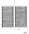
- Conductor structures arise, e.g. from different geometric Forms are composed, e.g. from strips of different orientation and width as well as rectangles, circles, trapezoids, etc, without that these conductor structures generate interference fields in the active measuring range. Examples of such conductor structures are shown in FIGS. 2a and 2b.
- the above ladder structures can also be identical, narrow Conductor sections exist, the closely consecutive and periodic are arranged continuously in the z-direction.
- the conductor sections must so closely follow each other that the ripple of them generated interference field in the active measuring range is negligibly small.
- the conductor sections are rectilinear within the conductor structure, are oriented parallel to the B 0 field and also extend over the entire length in the z-direction of the conductor structure, then they no longer need to be periodically continuous but may be arranged at arbitrary distances from each other transversely to the z-direction become. The reason for this is that each individual conductor section does not generate any inhomogeneities in the area of the active measuring volume.
- the present invention starts from several such Z-structures, which are arranged close to each other and / or one another, and builds the desired RF resonator from a certain area of these conductor structures.
- the remaining part of these conductor structures contributes only to the compensation of the susceptibility of the RF resonator and ideally should not carry any HF current.
- RF current should only flow in the RF resonator, and therefore it must be decoupled from the other conductors as well as possible.
- the remainder of the Z-structure which does not belong to the RF resonator, can also be modified according to Knowledge 4 , whereby, for example, vertical conductor arrangements can be converted into horizontal, thereby achieving a reduction of the RF coupling with the RF resonator.
- All of the following embodiments are based on only three Z-structures, two with parallel to the B 0 field and a perpendicular to the B 0 field oriented conductor sections, on a z-invariant surface in the radial (x, y) distance from the sample are arranged. These surfaces may in particular be flat or cylindrical.
- the first Z-structure consists of stripes parallel to the B 0 field, closely followed by a second one having stripes perpendicular to the B 0 field and closely followed by a third one with stripes parallel to B 0 -Field.
- FIG. 7 a An example of this is shown in FIG. 7 a, wherein the three Z-structures are arranged on one level and are selected such that an RF resonator of the type FIG. 10 a can be produced from the disclosure [1].
- the region of the Z structures from which the RF resonator is to be formed is shown hatched in FIG. 7a (region 7a).
- the predominantly field-producing conductors are produced from the left-hand Z-structure 8a, which is closest to the test sample, the upper and lower transverse conductors from the middle 9a, and the capacitive components from the right-hand 10a.
- the right-hand conductor pattern 10a has twice as many conductors as the left-hand conductor pattern 8a, so that the capacitive components can be generated.
- the problem lies in the generation of the corners of the RF resonator, which must arise from the hatched parts of the conductor structures 8a and 10a (FIG. 7a). This problem is solved in that certain hatched conductor portions are rotated or moved within their associated surface elements, which is allowed according to Knowledge 4 yes.
- Fig. 8a shows how this problem is solved.
- Starting from three ladders with the surface elements (A1 + A2 + A3), (B1 + B2 + B3) resp. (C1 + C2 + C3) become within the area elements A2, B2 and C2 the conductor parts S1, S3, S4, S5 and S6 are rotated and shifted, that a first corner of the RF resonator is formed.
- a second corner arises in an analogous manner within the surface elements B3 and C3.
- the result of this transformation is shown in Fig. 8b.
- FIG. 9a the entire structure of the RF resonator is obtained, as shown in FIG. 9a as a hatched area. This is magnetically virtually identical to the hatched area of FIG. 7a and therefore does not produce any interfering B z components in the active measuring range.
- the conductor structure of FIG. 9a has the disadvantage that the RF field lines of the RF resonator, the compensation structure of close together horizontal horizontal stripes must pierce and thereby be severely handicapped, because only small gaps exist are through which the field lines can find their way. Especially the horizontal stripes in area 7a, that of the RF resonator be enclosed, need the greatest concentration of field lines let through and therefore form the biggest obstacle.
- the two surfaces can e.g. through a thin, electrically insulating Foil be separated from each other, or one of the electrically insulating Carrier elements to lie on one of the two surfaces comes, could take over the function of the insulating film.
- an NMR resonator of the type Fig. 10a of the patent [1] is to be constructed. Again, one starts from three Z-structures, namely two, whose conductor elements are oriented parallel to the B 0 field (FIG. 10 a), and a third with conductor elements perpendicular to the B 0 field (FIG. 10 b). Although the two conductor structures in Fig. 10a and Fig. 10b are shown separately, but in fact they are exactly on top of each other, so that intersections and overlaps of the conductor elements are present.
- the cross-connections of the RF resonator are derived.
- the width L B of this Z-structure is equal to the width L A of the two Z-structures of FIG. 10 a, ie the three Z-structures overlap exactly.
- FIGS. 11a and 11b How these three Z-structures are distributed on the two surfaces is shown in FIGS. 11a and 11b.
- the first area ( Figure 11a) contains the entire RF resonator as well as the majority of the conductor structures with which the susceptibility of the conductors is compensated.
- the second surface (FIG. 11b) contains the remaining conductor structures with which the residual portion of the susceptibility is compensated. Note that the ladder structures on the two surfaces no longer have intersections or overlaps.
- the two combined conductor structures of Figures 11a and 11b are virtually identical to the two combined conductor structures of Figures 10a and 10b except for a negligible error due to the finite distance between the two surfaces. As we know from the original conductor structures (Figure 10a and 10b) that they do not produce B z components in the active measuring volume, this is of course now available for the new conductor structures (Fig. 11a and 11b) on the two surfaces.
- the advantage of this third embodiment lies in the greater possibilities new conductor structures for the RF receiver coil assemblies to design.
- the disadvantage is that two individual support elements or a carrier element coated on both sides is required are resp. is, whose structures are exactly positioned on each other have to.
- Fig. 2c shows a resonator modified according to these instructions, in which the interference is much lower than in the known resonator of Fig. 2e.
- resonators with oblique Fingers spiraling over an angular range of 2 ⁇ around a cylindrical surface are wound.
- Fig. 2f shows the uncorrected
- Fig. 2d the corrected resonator.
- the conductors of the compensation arrangement can additionally with narrow interruptions are provided to the RF coupling with to minimize the RF resonator.
- Such interruptions are shown in Fig. 9c for the second embodiment (Fig. 9b), but they can be realize in all other embodiments, even if they are not explicitly shown there.
Landscapes
- Physics & Mathematics (AREA)
- Condensed Matter Physics & Semiconductors (AREA)
- General Physics & Mathematics (AREA)
- Magnetic Resonance Imaging Apparatus (AREA)
Abstract
Description
- Fig. 1
- Zeigt eine Ausführungsform des erfindungsgemäßen NMR-Resonators, bei der die Leiterstrukturen auf einer Zylinderoberfläche liegen. Nicht eingezeichnet sind die normalerweise vorhandenen elektrischen Unterbrüche in den Kompensationsstrukturen, welche eine bessere HF-Entkopplung zwischen diesen Strukturen und den Strukturen des HF-Resonators erlauben.
- Fig. 2a
- Zeigt den NMR-Resonator von Fig. 1, der auf eine Ebene abgewickelt wurde. Die unter Fig. 1 erwähnten elektrischen Unterbrüche sind hier eingezeichnet und deutlich erkennbar.
- Fig. 2b
- Zeigt eine weitere Möglichkeit, wie die Kompensations-Struktur gestaltet werden kann, nämlich mit punktförmigen Leitern anstatt geraden Leitern. Der Massenanteil pro Flächenelement der punktförmigen sowie der horizontalen Leitern muss entlang den Flächenelementen, die sich nur in ihrer z-Position unterscheiden, gleich groß sein, damit eine optimale Kompensation der Suszeptibilität der Leiter erreicht wird.
- Fig. 2c
- Zeigt einen NMR-Resonator, bei dem der Resonator aus einzelnen Fingern besteht, die ineinander greifen, kapazitiv miteinander koppeln und gesamthaft einen sogenannten Birdcage-Resonator darstellen. Die einzelnen Finger sind parallel zur z-Achse, d.h. parallel zum B0-Feld angeordnet. Die Kompensationsstrukturen befinden sich oberhalb und unterhalb der Fingeranordnungen. Sie entstehen durch Anbringen einer Vielzahl von rechteckigen Löchern und erlauben, dass Ströme sowohl parallel wie auch senkrecht zur z-Achse fließen können.
- Fig. 2d
- Wie Fig. 2c jedoch mit schrägen Fingern, die spiralförmig über einen Winkelbereich von 2π um die Zylinderfläche gewickelt sind. Diese Anordnung hat den Vorteil, dass bei mehreren, konzentrisch zueinander positionierten Anordnungen, praktisch keine HF-Kopplung zwischen den einzelnen Anordnungen vorhanden ist.
- Fig. 2e
- Wie Fig. 2c jedoch ohne Kompensationsstruktur. Diese Anordnung entspricht dem Stand der Technik.
- Fig. 2f
- Wie Fig. 2d jedoch ohne Kompensationsstruktur. Diese Anordnung entspricht dem Stand der Technik.
- Fig. 3
- Feld ΔB, das von einem diamagnetischen Leiterstreifen erzeugt wird, dessen Längsachse parallel zu B0 steht. Die z-Komponente (ΔBZ)1 des Feldes ΔB ist im Bereich des aktiven Messvolumens 1 praktisch Null und tritt nur am oberen und unteren Rand des Streifens auf.
- Fig. 4
- Feld ΔB, das von einem diamagnetischen Leiterstreifen erzeugt wird, dessen Längsachse senkrecht zu B0 steht. Im Bereich des aktiven Messvolumens 1 sind die z-Komponenten (ΔBZ)1 des Feldes ΔB stark inhomogen.
- Fig. 5
- Anordnung aus mehreren Leiterstreifen 4a, 4b, 4c bis 4k, die auf einer Ebene parallel zu B0 liegen und gleichmäßig übereinander angeordnet sind. Die BZ-Komponente (ΔBZ)1 der einzelnen Streifen überlagern sich und erzeugen das Feld (ΔBZ)tot. Dieses ist im Bereich des aktiven Messvolumens 1 praktisch Null und besitzt dort nur sehr kleine Bz-Komponenten, die mit Hilfe des Raumtemperatur-Shimsystems problemlos zu kompensieren sind. Stärkere BZ-Komponenten treten nur im Bereich des oberen und unteren Endes des Streifens auf, d.h. in einem Bereich, der praktisch keinen Einfluss auf das aktive Messvolumen besitzt.
- Fig. 6a
- Leiterstruktur, die aus parallel und senkrecht zum B0-Feld orientierten Streifen zusammengesetzt ist. Die Streifen sind so verteilt, dass überall gleich viel Leitermaterial pro Flächenelement vorhanden ist. Dadurch können Störfelder nur am oberen und unteren Rand der gesamten Leiterstruktur entstehen.
- Fig. 6b
- Leiterstruktur, die aus parallel zum B0-Feld orientierten Streifen sowie aus kreisförmigen Leiterpunkten zusammengesetzt ist. Die Streifen und Leiterpunkte sind so verteilt, dass überall gleich viel Leitermaterial pro Flächenelement vorhanden ist. Dadurch können Störfelder nur am oberen und unteren Rand der gesamten Leiterstruktur entstehen.
- Fig. 7a
- Leiterstruktur, die eine konstante Breite besitzt, in z-Richtung stark ausgedehnt ist und aus drei Teilstrukturen aufgebaut ist, nämlich zwei mit Streifen parallel und eine mittlere mit Steifen senkrecht zum B0-Feld. Aus dem schraffierten Bereich 7a lässt sich der HF-Resonator aufbauen. Die übrigen Bereiche sind erforderlich, um den Suszeptibilitätseinfluss des HF-Resonators zu kompensieren.
- Fig. 7b
- Leiterstruktur wie in Fig. 7a, jedoch mit dem Unterschied, dass die Streifen der mittleren Teilstruktur einen größeren Abstand zueinander haben. Dadurch wird die HF-Durchlässigkeit dieser Teilstruktur verbessert.
- Fig. 8a
- Ausschnitt des oberen Endes des schraffierten Teils der Teilstruktur 8a in Fig. 7a. Die Darstellung zeigt, wie z.B. Flächenanteile s1, s3, s4, s5 und s6 der Leiterstruktur innerhalb den zugehörigen Flächenelementen A2, B2 resp.C2 verschoben und gedreht werden müssen, um eine Ecke des HF-Resonators zu konstruieren.
- Fig. 8b
- Resultierende Leiterstruktur nach erfolgter Verschiebung und Drehung einiger Flächenanteile, wie dies in Fig. 8a dargestellt ist.
- Fig. 9a
- Zeigt die erste Ausführungsform eines erfindungsgemäßen Resonators, der aus der schraffierten Struktur von Fig. 7a und unter Verwendung des Transformationsvorganges gemäß Fig. 8a erzeugt wurde. Der Bereich 7a, in dem der HF-Strom fließt, ist schraffiert markiert. Die gesamte Leiterstruktur erzeugt praktisch keine Störfelder im aktiven Messbereich!
- Fig. 9b
- Zeigt die zweite Ausführungsform eines erfindungsgemäßen Resonators, der aus der schraffierten Struktur von Fig. 7b und unter Verwendung der Transformationsvorganges gemäß Fig. 8a erzeugt wurde. Der Bereich 7b, in dem der HF-Strom fließt, ist schraffiert markiert. Die gesamte Leiterstruktur er erzeugt praktisch keine Störfelder im aktiven Messbereich!
- Fig. 9c
- Zeigt nochmals die zweite Ausführungsform des erfindungsgemäßen Resonators von Fig. 9b mit dem Unterschied jedoch, dass die Leiter der Kompensationsstruktur unterteilt sind. Dadurch lässt sich die HF-Kopplung zwischen HF-Resonator und Kompensationsstruktur stark verringern.
- Fig. 10a
- Zeigt zwei Leiterstrukturen, deren Leiter parallel zur z-Achse orientiert sind, und aus denen ein Teil der dritten Ausführungsform eines erfindungsgemäßen Resonators hergestellt wird.
- Fig. 10b
- Zeigt eine Leiterstruktur, deren Leiter senkrecht zur z-Achse orientiert sind, und aus denen ein Teil der dritten Ausführungsform eines erfindungsgemäßen Resonators hergestellt wird.
- Fig. 11a
- Leiterstruktur auf der ersten der beiden Flächen der dritten Ausführungsform eines erfindungsgemäßen Resonators. Das Substrat enthält den HF-Resonator 7d und den Hauptanteil der Kompensations-Anordnung.
- Fig. 11b
- Leiterstruktur auf der zweiten der beiden Flächen der dritten Ausführungsform eines erfindungsgemäßen Resonators. Mit dieser Leiterstruktur wird der Restanteil der Kompensations-Anordnung realisiert. Diese kann nicht auf der ersten Fläche angebracht werden, weil sonst verschiedene Leiter sich kreuzen oder überlappen würden.
- B0
- Statisches Magnetfeld des NMR-Magneten.
- ΔB
- Störfeld, das durch die Suszeptibilität des Leiters erzeugt wird.
- (ΔBZ)1
- z-Komponente des Störfeldes ΔB, die von einem einzelnen Leiterstreifen 2 oder 4 verursacht wird.
- (ΔBZ)tot
- z-Komponente von ΔB, die von allen Leiterstreifen der Anordnung 5 verursacht wird.
- S1, S3, S4, S5, S6
- Einzelne Leiteranteile, die innerhalb ihrer Flächenelemente gedreht und verschoben werden, um dadurch die Ecken des HF-Resonators herzustellen.
- 1
- Aktives Messvolumen.
- 2
- Langer flacher Leiter, dessen Längsachse parallel zum B0-Feld orientiert ist.
- 3
- Magnetische Dipole innerhalb des Streifens 2.
- 4
- Flacher Leiter, dessen Längsachse senkrecht zum B0-Feld orientiert ist.
- 4a, 4b, 4c, ..., 4k
- Leiterstreifen wie unter 4 beschrieben, die zur Leiteranordnung 5 gehören.
- 5
- Anordnung aus mehreren Leiterstreifen 4a, 4b, 4c, ... ,4k, die auf einer Ebene parallel zum B0-Feld liegen und in z-Richtung gleichmäßig nebeneinander angeordnet sind.
- 6 7a, 7b, 7c, 7d
- Bereiche der diversen HF-Empfangsspulenanordnungen, in denen sich die Leiterabschnitte befinden, die HF-Ströme tragen und zum HF-Resonator gehören.
- 8a, 8b
- Z-Strukturen mit Leiterelementen, die parallel zum B0-Feld orientiert sind, und die teilweise dazu benutzt werden, jene Leiteranteile des HF-Resonators herzustellen, die am nächsten zum aktiven Messbereich liegen und dort den Hauptanteil des HF-Feldes erzeugen.
- 9a, 9b
- Z-Strukturen mit Leiterelementen, die senkrecht zum B0-Feld orientiert sind, und die teilweise dazu benutzt werden, um die horizontalen Querverbindungen im oberen und unteren Bereich des HF-Resonators herzustellen.
- 10a, 10b
- Z-Strukturen mit Leiterelementen, die parallel zum B0-Feld orientiert sind, und die teilweise dazu benutzt werden, die kapazitiven Anteile des HF-Resonators herzustellen.
Claims (20)
- HF(=Hochfrequenz)-Empfangsspulenanordnung für einen NMR(= Kernspinresonanz)-Resonator mit mindestens einem HF-Resonator zum Aussenden und/oder Empfangen von HF-Signalen auf einer oder mehreren gewünschten Resonanzfrequenzen in eine und/oder aus einer Messprobe in einem um einen Koordinatenursprung (x,y,z = 0) angeordneten Untersuchungsvolumen einer NMR-Apparatur mit einer Einrichtung zur Erzeugung eines homogenen Magnetfelds B0 in Richtung einer z-Achse, wobei zwischen z = -|z1| und z = +|z2| normalleitende, induktiv und zum Teil auch kapazitiv wirkende Leiterstrukturen des HF-Resonators im wesentlichen auf einer in z-Richtung translations-invarianten (= z-invarianten) Fläche im radialen (x,y) Abstand senkrecht zur z-Achse angeordnet sind,
dadurch gekennzeichnet, dass auf der z-invarianten Fläche zusätzlich eine Kompensations-Anordnung vorgesehen ist, die sich mindestens bis zu Werten z < -|z1| -0.5 |r| und z > +|z2| + 0.5 |r| erstreckt, wobei |r| der kleinste vorkommende Abstand zwischen der Messprobe und der Kompensations-Anordnung bedeutet, dass die Kompensations-Anordnung weitere normalleitende Leiterstrukturen umfasst, welche HF-mäßig vom HF-Resonator weitgehend entkoppelt sind, dass die Leiterstrukturen der Kompensations-Anordnung und des HF-Resonators ihrerseits aus einzelnen, normalleitende Strukturen enthaltenden Flächenabschnitten (="Z-Strukturen") zusammengesetzt sind, die in der z-invarianten Fläche liegen, jeweils über die ganze Länge in z-Richtung der Leiterstrukturen der Kompensations-Anordnung und des HF-Resonators verlaufen, und deren Strukturen so angeordnet sind, dass bei einer geeigneten mathematischen Zerlegung der Fläche der Z-Strukturen in eine Vielzahl kleiner, gleich großer Flächenelemente, in allen Flächenelementen, die sich nur in ihrer z-Position unterscheiden, eine weitgehend gleiche Masse von normalleitendem Material enthalten ist. - HF-Empfangsspulenanordnung nach Anspruch 1, dadurch gekennzeichnet, dass die Gesamtzahl der Flächenelemente größer ist als 50, vorzugsweise größer als 200.
- HF-Empfangsspulenanordnung nach einem der vorhergehenden Ansprüche, dadurch gekennzeichnet, dass die Anzahl der Flächenelemente, die sich nur durch ihre z-Position unterscheiden, größer ist als 20, vorzugsweise größer als 50.
- HF-Empfangsspulenanordnung nach einem der vorhergehenden Ansprüche, dadurch gekennzeichnet, dass die Leiterstrukturen der Kompensations-Anordnung den HF-Resonator beidseits jeweils um mindestens die halbe, vorzugsweise etwa die zweifache Ausdehnung des HF-Resonators in z-Richtung überragen.
- HF-Empfangsspulenanordnung nach einem der vorhergehenden Ansprüche, dadurch gekennzeichnet, dass die induktiv und zum Teil auch kapazitiv wirkenden Leiterstrukturen des oder der HF-Resonatoren sowie die Leiterstrukturen der Kompensations-Anordnung(en) auf ebenen Substratelementen aufgebracht sind, die untereinander und zur z-Achse parallel angeordnet sind.
- HF-Empfangsspulenanordnung nach einem der vorhergehenden Ansprüche, dadurch gekennzeichnet, dass die induktiv und zum Teil auch kapazitiv wirkenden Leiterstrukturen des oder der HF-Resonatoren sowie die Leiterstrukturen der Kompensations-Anordnung(en) auf zylinderförmigen Substratelementen aufgebracht sind, die untereinander konzentrisch und zur z-Achse parallel angeordnet sind.
- HF-Empfangsspulenanordnung nach einem der vorhergehenden Ansprüche, dadurch gekennzeichnet, dass die induktiv und zum Teil auch kapazitiv wirkenden Leiterstrukturen des HF-Resonators sowie die Leiterstrukturen der zugehörigen Kompensations-Anordnung in derselben Ebene oder auf derselben Zylinderfläche angeordnet sind.
- HF-Empfangsspulenanordnung nach einem der vorhergehenden Ansprüche, dadurch gekennzeichnet, dass die Strukturen des HF-Resonators und der zugehörigen Kompensationsanordnung in zwei oder mehreren ebenen oder zylinderförmigen Teilflächen liegen, die parallel resp. konzentrisch zueinander angeordnet sind, wobei in der ersten Teilfläche die induktiv und zum Teil auch kapazitiv wirkenden Leiterstrukturen des HF-Resonators sowie Teile der zugehörigen Leiterstrukturen der Kompensations-Anordnung, in den weiteren Teilflächen die verbleibenden Teile der Leiterstrukturen der Kompensations-Anordnung angeordnet sind.
- HF-Empfangsspulenanordnung nach Anspruch 8, dadurch gekennzeichnet, dass die Abstände zwischen den Teilflächen, gemessen in einer Richtung senkrecht zu den Teilflächen, maximal 600µm, vorzugsweise maximal zwischen 50 und 200µm betragen.
- HF-Empfangsspulenanordnung nach einem der vorhergehenden Ansprüche, dadurch gekennzeichnet, dass die Leiterstrukturen der Kompensations-Anordnung und des HF-Resonators auf derselben Teilfläche der z-invarianten Fläche angeordnet sind.
- HF-Empfangsspulenanordnung nach einem der vorhergehenden Ansprüche, dadurch gekennzeichnet, dass zumindest ein Teil der Abschnitte der Leiterstrukturen streifenförmig achsparallel oder achssenkrecht zur z-Richtung angeordnet ist.
- HF-Empfangsspulenanordnung nach einem der vorhergehenden Ansprüche, dadurch gekennzeichnet, dass die Strukturen auf den z-invarianten Flächen aus verschiedenen geometrischen Formen zusammengesetzt sind, z.B. aus Streifen verschiedener Orientierung und Breite sowie aus Rechtecken, Kreisen, Trapezen, etc.
- HF-Empfangsspulenanordnung nach einem der vorhergehenden Ansprüche, dadurch gekennzeichnet, dass eine oder mehrere seiner Z-Strukturen aus identischen, schmalen Leitern aufgebaut ist, die eng aufeinander folgend und periodisch kontinuierlich in z-Richtung angeordnet sind, wobei der Abstand benachbarter Leiter klein gegenüber dem kleinsten Abstand zum Untersuchungsvolumen ist.
- HF-Empfangsspulenanordnung nach einem der vorhergehenden Ansprüche, dadurch gekennzeichnet, dass eine oder mehrere seiner Z-Strukturen aus Leitern bestehen, die parallel zur z-Achse ausgerichtet sind und gleiche oder unterschiedliche Abstände zueinander haben.
- HF-Empfangsspulenanordnung nach einem der vorhergehenden Ansprüche, dadurch gekennzeichnet, dass die Leiterstrukturen, die nicht zum HF-Resonator gehören, eine Anzahl von schmalen Unterbrüchen enthalten, die über Teile oder die ganze Länge der einzelnen Leiterabschnitte verteilt sind.
- HF-Empfangsspulenanordnung nach einem der Ansprüche 1 bis 11, dadurch gekennzeichnet, dass die Erzeugung des HF-Resonators aus den gewünschten Bereichen der Z-Strukturen dadurch erreicht wird, dass innerhalb von kleinen Flächenelementen der Z-Strukturen der darin enthaltene Leiter oder Teile davon gedreht oder verschoben werden, und/oder dass schmale Abstände zwischen den Leitern galvanisch verbunden werden, und/oder dass schmale Unterbrüche in den Leitern angebracht werden, und/oder dass schräge Z-Strukturen verwendet werden, und/oder dass die Z-Strukturen auf zwei oder mehreren Teilflächen verteilt werden.
- HF-Empfangsspulenanordnung nach einem der Ansprüche 1 bis 14 oder 16, dadurch gekennzeichnet, dass diese aus drei Z-Strukturen aufgebaut ist, nämlich links und rechts je eine mit vertikalen und dazwischen eine mit horizontalen geraden Streifen.
- HF-Empfangsspulenanordnung nach einem der Ansprüche 1 bis 16, dadurch gekennzeichnet, dass diese aus drei Z-Strukturen zusammengesetzt ist, nämlich aus einer ersten und zweiten mit parallel zur z-Achse sowie einer dritten mit in z periodisch und quer zur z-Achse angeordneten Streifen, wobei die dritte Z-Struktur über den beiden ersten, die einen bestimmten Abstand zueinander haben, positioniert ist und diese genau überdeckt, und wobei die Zusammensetzung des HF-Resonators und der Kompensationsstruktur dadurch erfolgt, dass die drei Z-Strukturen teilweise zerlegt und auf zwei separaten Teilflächen, die zu einem oder zwei Substraten gehören, verteilt werden, wobei die erste Teilfläche den ganzen HF-Resonator mit dem Hauptanteil der Kompensations-Struktur, und die zweite Teilfläche den Restanteil der Kompensations-Struktur enthält, und dass die so entstandenen Strukturen auf den beiden Teilflächen derart aufeinander positioniert werden, dass die Summe ihrer Strukturen wieder gleich der Summe der ursprünglichen drei Z-Strukturen ist, und dass dadurch ein funktionsfähiger NMR-Resonator entsteht.
- NMR-Resonator, der eine oder mehrere HF-Empfangsspulenanordnungen nach einem der vorhergehenden Ansprüche umfasst.
- NMR-Resonator nach Anspruch 19, der aus mehreren, vorzugsweise 2 oder 4 HF-Empfangsspulenanordnungen nach einem der Ansprüche 1 bis 18 aufgebaut ist, wobei diese HF-Empfangsspulenanordnungen miteinander HF-mäßig koppeln und auf unterschiedlichen Teilflächen der z-invarianten Fläche liegen.
Applications Claiming Priority (2)
| Application Number | Priority Date | Filing Date | Title |
|---|---|---|---|
| DE10205625 | 2002-02-12 | ||
| DE10205625A DE10205625C1 (de) | 2002-02-12 | 2002-02-12 | HF-Empfangsspulenanordnung für einen normalleitenden NMR-Resonator mit makroskopisch homogener Verteilung des leitenden Materials |
Publications (3)
| Publication Number | Publication Date |
|---|---|
| EP1335212A2 true EP1335212A2 (de) | 2003-08-13 |
| EP1335212A3 EP1335212A3 (de) | 2005-01-05 |
| EP1335212B1 EP1335212B1 (de) | 2008-04-09 |
Family
ID=7713780
Family Applications (1)
| Application Number | Title | Priority Date | Filing Date |
|---|---|---|---|
| EP03002283A Expired - Lifetime EP1335212B1 (de) | 2002-02-12 | 2003-02-03 | HF-Empfangsspulenanordnung für einen normalleitenden NMR-Resonator mit makroskopisch homogener Verteilung des leitenden Materials |
Country Status (4)
| Country | Link |
|---|---|
| US (1) | US6781377B2 (de) |
| EP (1) | EP1335212B1 (de) |
| JP (1) | JP4365112B2 (de) |
| DE (2) | DE10205625C1 (de) |
Families Citing this family (25)
| Publication number | Priority date | Publication date | Assignee | Title |
|---|---|---|---|---|
| DE102004020167B4 (de) * | 2004-04-24 | 2012-01-05 | Bruker Biospin Ag | Hochfrequenz-Resonatorsystem mit optimierter Stromverteilung in den Leiterelementen und Verfahren zu dessen Design |
| DE102007002440B4 (de) | 2007-01-11 | 2008-09-25 | Technische Universität Chemnitz | Suszeptiblitätskompensierte Detektoreinrichtung für Kernspinresonanz-Messungen kleiner Probenvolumen |
| US8125226B2 (en) * | 2009-07-02 | 2012-02-28 | Agilent Technologies, Inc. | Millipede surface coils |
| CN104459584B (zh) * | 2009-12-02 | 2018-03-20 | 纳纳利塞斯公司 | 用于产生均匀磁场的方法和装置 |
| US9391565B2 (en) | 2013-03-15 | 2016-07-12 | TriQuint International PTE, Ltd. | Amplifier phase distortion correction based on amplitude distortion measurement |
| US9444417B2 (en) | 2013-03-15 | 2016-09-13 | Qorvo Us, Inc. | Weakly coupled RF network based power amplifier architecture |
| US9774311B2 (en) | 2013-03-15 | 2017-09-26 | Qorvo Us, Inc. | Filtering characteristic adjustments of weakly coupled tunable RF filters |
| US9780756B2 (en) | 2013-08-01 | 2017-10-03 | Qorvo Us, Inc. | Calibration for a tunable RF filter structure |
| US9685928B2 (en) | 2013-08-01 | 2017-06-20 | Qorvo Us, Inc. | Interference rejection RF filters |
| US9866197B2 (en) | 2013-06-06 | 2018-01-09 | Qorvo Us, Inc. | Tunable RF filter based RF communications system |
| US9899133B2 (en) | 2013-08-01 | 2018-02-20 | Qorvo Us, Inc. | Advanced 3D inductor structures with confined magnetic field |
| US9825656B2 (en) | 2013-08-01 | 2017-11-21 | Qorvo Us, Inc. | Weakly coupled tunable RF transmitter architecture |
| US12224096B2 (en) | 2013-03-15 | 2025-02-11 | Qorvo Us, Inc. | Advanced 3D inductor structures with confined magnetic field |
| US9705478B2 (en) | 2013-08-01 | 2017-07-11 | Qorvo Us, Inc. | Weakly coupled tunable RF receiver architecture |
| US9755671B2 (en) | 2013-08-01 | 2017-09-05 | Qorvo Us, Inc. | VSWR detector for a tunable filter structure |
| US20150092625A1 (en) * | 2013-03-15 | 2015-04-02 | Rf Micro Devices, Inc. | Hybrid active and passive tunable rf filters |
| US9628045B2 (en) | 2013-08-01 | 2017-04-18 | Qorvo Us, Inc. | Cooperative tunable RF filters |
| US9871499B2 (en) | 2013-03-15 | 2018-01-16 | Qorvo Us, Inc. | Multi-band impedance tuners using weakly-coupled LC resonators |
| US9859863B2 (en) | 2013-03-15 | 2018-01-02 | Qorvo Us, Inc. | RF filter structure for antenna diversity and beam forming |
| US9800282B2 (en) | 2013-06-06 | 2017-10-24 | Qorvo Us, Inc. | Passive voltage-gain network |
| US9705542B2 (en) | 2013-06-06 | 2017-07-11 | Qorvo Us, Inc. | Reconfigurable RF filter |
| US9780817B2 (en) | 2013-06-06 | 2017-10-03 | Qorvo Us, Inc. | RX shunt switching element-based RF front-end circuit |
| US9966981B2 (en) | 2013-06-06 | 2018-05-08 | Qorvo Us, Inc. | Passive acoustic resonator based RF receiver |
| US10796835B2 (en) | 2015-08-24 | 2020-10-06 | Qorvo Us, Inc. | Stacked laminate inductors for high module volume utilization and performance-cost-size-processing-time tradeoff |
| US11139238B2 (en) | 2016-12-07 | 2021-10-05 | Qorvo Us, Inc. | High Q factor inductor structure |
Family Cites Families (13)
| Publication number | Priority date | Publication date | Assignee | Title |
|---|---|---|---|---|
| US4563648A (en) * | 1983-09-22 | 1986-01-07 | Varian Associates, Inc. | Geometric compensation of magnetic susceptibility perturbations in an RF spectrometer |
| US4694255A (en) * | 1983-11-04 | 1987-09-15 | General Electric Company | Radio frequency field coil for NMR |
| US5565778A (en) * | 1992-06-01 | 1996-10-15 | Conductus, Inc. | Nuclear magnetic resonance probe coil |
| US5585723A (en) * | 1995-03-23 | 1996-12-17 | Conductus, Inc. | Inductively coupled superconducting coil assembly |
| EP0766832B1 (de) * | 1995-04-18 | 2005-07-06 | Koninklijke Philips Electronics N.V. | Rf-spulenanordnung für ein gerät für magnetische resonanzuntersuchungen |
| DE19515586A1 (de) * | 1995-04-27 | 1996-10-31 | Siemens Ag | Hochfrequenz-Antennensystem eines Gerätes zur magnetischen Kernresonanz |
| US5998999A (en) * | 1996-12-12 | 1999-12-07 | Picker International, Inc. | Volume RF coils with integrated high resolution focus coils for magnetic resonance imaging |
| US6100694A (en) * | 1999-02-24 | 2000-08-08 | Varian, Inc. | Multiple-tuned bird cage coils |
| US6285189B1 (en) * | 1999-09-04 | 2001-09-04 | Varian, Inc. | Millipede coils |
| US6420871B1 (en) * | 2001-03-02 | 2002-07-16 | Varian, Inc. | Multiple tuned birdcage coils |
| US6556013B2 (en) * | 2001-03-09 | 2003-04-29 | Bruker Biospin Corp. | Planar NMR coils with localized field-generating and capacitive elements |
| US6552544B2 (en) * | 2001-04-05 | 2003-04-22 | Varian, Inc. | Detunable coil assembly and method of detuning RF coil for MRI |
| US6661229B2 (en) * | 2001-04-30 | 2003-12-09 | Ge Medical Systems Global Technology Company, Llc | RF birdcage coil with reduced acoustic noise |
-
2002
- 2002-02-12 DE DE10205625A patent/DE10205625C1/de not_active Expired - Fee Related
-
2003
- 2003-01-30 US US10/353,937 patent/US6781377B2/en not_active Expired - Lifetime
- 2003-02-03 DE DE50309560T patent/DE50309560D1/de not_active Expired - Lifetime
- 2003-02-03 EP EP03002283A patent/EP1335212B1/de not_active Expired - Lifetime
- 2003-02-12 JP JP2003034303A patent/JP4365112B2/ja not_active Expired - Fee Related
Also Published As
| Publication number | Publication date |
|---|---|
| US20030151409A1 (en) | 2003-08-14 |
| JP2004003968A (ja) | 2004-01-08 |
| DE50309560D1 (de) | 2008-05-21 |
| EP1335212B1 (de) | 2008-04-09 |
| US6781377B2 (en) | 2004-08-24 |
| EP1335212A3 (de) | 2005-01-05 |
| DE10205625C1 (de) | 2003-07-24 |
| JP4365112B2 (ja) | 2009-11-18 |
Similar Documents
| Publication | Publication Date | Title |
|---|---|---|
| EP1335212B1 (de) | HF-Empfangsspulenanordnung für einen normalleitenden NMR-Resonator mit makroskopisch homogener Verteilung des leitenden Materials | |
| DE102005056602B4 (de) | Resonator für Magnetresonanzanwendungen | |
| DE102004035851B4 (de) | Resonatorsystem zur Erzeugung eines Hochfrequenz-Magnetfelds | |
| EP0223284B1 (de) | Hochfrequenz-Spulenanordnung für Kernspinresonanzgerät | |
| DE2814505A1 (de) | Antennenanordnung fuer einen vorgegebenen frequenzbereich mit entsprechenden resonanzraeumen | |
| DE102006017438A1 (de) | Resonator für Magnetresonanzanwendungen | |
| EP1251361A2 (de) | Supraleitende Resonatoren für Anwendungen in der NMR | |
| DE2814504A1 (de) | Schichtartig aufgebaute antennenanordnung fuer orthogonal polarisierte strahlung | |
| DE19527921A1 (de) | Doppelseitige HF-Abschirmung für eine Spule in Gradienten-Spulen für Hochgeschwindigkeits MR-Bildgebung | |
| DE10244173B4 (de) | Antennenanordnung für ein Magnetresonanzgerät, Magnetresonanz-Antennensystem, Magnetresonanzgerät sowie Verfahren zur Verkopplung zweier Antennengruppen | |
| DE60118993T2 (de) | Über die NMR-Sonde verteilte kapazitive Einschübe | |
| EP1746432B1 (de) | HF-Schirm mit reduzierter Kopplung zum HF-Resonatorsystem | |
| DE10146338B4 (de) | Zirkularpolarisationswellenantenne und Herstellungsverfahren derselben | |
| DE102009042940A1 (de) | Positionsmesseinrichtung mit sich mehrfach kreuzender Senderwindungsanordnung | |
| DE102021134289A1 (de) | Sensorwicklungskonfiguration für induktiven positionscodierer | |
| EP1302780B1 (de) | Supraleitende NMR-Resonatoren mit makroskopisch homogener Verteilung des Supraleiters | |
| DE102020115424A1 (de) | Induktiver Positionssensor | |
| EP0689723B1 (de) | Halleffekt-einrichtung mit strom- und hallspannungs-anschlüssen | |
| EP1589347B1 (de) | Hochfrequenz-Resonatorsystem mit optimierter Stromverteilung in den Leiterelementen | |
| DE102012217760A1 (de) | Entkopplung von Split-Ring-Resonatoren bei der Magnetresonanztomographie | |
| DE102011006573B4 (de) | Verfahren zur Ermittlung einer optimalen Struktur eines Hochfrequenzschirms einer Hochfrequenzantenne einer Magnetresonanzanordnung | |
| DE2003713A1 (de) | Zirkulator | |
| EP3358674B1 (de) | Biegsame antennenanordnung | |
| EP1298757A1 (de) | Bandpassfilter für ein Hochfrequenzsignal und Abstimmverfahren dafür | |
| DE4036841C2 (de) | Mit magnetostatischen Wellen arbeitende Einrichtung |
Legal Events
| Date | Code | Title | Description |
|---|---|---|---|
| PUAI | Public reference made under article 153(3) epc to a published international application that has entered the european phase |
Free format text: ORIGINAL CODE: 0009012 |
|
| AK | Designated contracting states |
Designated state(s): AT BE BG CH CY CZ DE DK EE ES FI FR GB GR HU IE IT LI LU MC NL PT SE SI SK TR |
|
| AX | Request for extension of the european patent |
Extension state: AL LT LV MK RO |
|
| PUAL | Search report despatched |
Free format text: ORIGINAL CODE: 0009013 |
|
| AK | Designated contracting states |
Kind code of ref document: A3 Designated state(s): AT BE BG CH CY CZ DE DK EE ES FI FR GB GR HU IE IT LI LU MC NL PT SE SI SK TR |
|
| AX | Request for extension of the european patent |
Extension state: AL LT LV MK RO |
|
| 17P | Request for examination filed |
Effective date: 20041208 |
|
| AKX | Designation fees paid |
Designated state(s): CH DE FR GB LI |
|
| 17Q | First examination report despatched |
Effective date: 20070109 |
|
| GRAP | Despatch of communication of intention to grant a patent |
Free format text: ORIGINAL CODE: EPIDOSNIGR1 |
|
| GRAS | Grant fee paid |
Free format text: ORIGINAL CODE: EPIDOSNIGR3 |
|
| GRAA | (expected) grant |
Free format text: ORIGINAL CODE: 0009210 |
|
| AK | Designated contracting states |
Kind code of ref document: B1 Designated state(s): CH DE FR GB LI |
|
| REG | Reference to a national code |
Ref country code: GB Ref legal event code: FG4D Free format text: NOT ENGLISH |
|
| REG | Reference to a national code |
Ref country code: CH Ref legal event code: EP |
|
| REF | Corresponds to: |
Ref document number: 50309560 Country of ref document: DE Date of ref document: 20080521 Kind code of ref document: P |
|
| ET | Fr: translation filed | ||
| PLBE | No opposition filed within time limit |
Free format text: ORIGINAL CODE: 0009261 |
|
| STAA | Information on the status of an ep patent application or granted ep patent |
Free format text: STATUS: NO OPPOSITION FILED WITHIN TIME LIMIT |
|
| 26N | No opposition filed |
Effective date: 20090112 |
|
| REG | Reference to a national code |
Ref country code: FR Ref legal event code: PLFP Year of fee payment: 14 |
|
| REG | Reference to a national code |
Ref country code: FR Ref legal event code: PLFP Year of fee payment: 15 |
|
| REG | Reference to a national code |
Ref country code: FR Ref legal event code: PLFP Year of fee payment: 16 |
|
| PGFP | Annual fee paid to national office [announced via postgrant information from national office to epo] |
Ref country code: GB Payment date: 20190221 Year of fee payment: 17 Ref country code: DE Payment date: 20190219 Year of fee payment: 17 Ref country code: CH Payment date: 20190221 Year of fee payment: 17 |
|
| PGFP | Annual fee paid to national office [announced via postgrant information from national office to epo] |
Ref country code: FR Payment date: 20190221 Year of fee payment: 17 |
|
| REG | Reference to a national code |
Ref country code: DE Ref legal event code: R082 Ref document number: 50309560 Country of ref document: DE Representative=s name: KOHLER SCHMID MOEBUS PATENTANWAELTE PARTNERSCH, DE Ref country code: DE Ref legal event code: R081 Ref document number: 50309560 Country of ref document: DE Owner name: BRUKER SWITZERLAND AG, CH Free format text: FORMER OWNER: BRUKER BIOSPIN AG, FAELLANDEN, CH |
|
| REG | Reference to a national code |
Ref country code: CH Ref legal event code: PFA Owner name: BRUKER SWITZERLAND AG, CH Free format text: FORMER OWNER: BRUKER BIOSPIN AG, CH |
|
| REG | Reference to a national code |
Ref country code: DE Ref legal event code: R119 Ref document number: 50309560 Country of ref document: DE |
|
| REG | Reference to a national code |
Ref country code: CH Ref legal event code: PL |
|
| GBPC | Gb: european patent ceased through non-payment of renewal fee |
Effective date: 20200203 |
|
| PG25 | Lapsed in a contracting state [announced via postgrant information from national office to epo] |
Ref country code: CH Free format text: LAPSE BECAUSE OF NON-PAYMENT OF DUE FEES Effective date: 20200229 Ref country code: LI Free format text: LAPSE BECAUSE OF NON-PAYMENT OF DUE FEES Effective date: 20200229 |
|
| PG25 | Lapsed in a contracting state [announced via postgrant information from national office to epo] |
Ref country code: DE Free format text: LAPSE BECAUSE OF NON-PAYMENT OF DUE FEES Effective date: 20200901 Ref country code: GB Free format text: LAPSE BECAUSE OF NON-PAYMENT OF DUE FEES Effective date: 20200203 Ref country code: FR Free format text: LAPSE BECAUSE OF NON-PAYMENT OF DUE FEES Effective date: 20200229 |