EP1335059A1 - Machine à tambour équipée d'un ensemble capteur de paramètres de rotation du tambour - Google Patents
Machine à tambour équipée d'un ensemble capteur de paramètres de rotation du tambour Download PDFInfo
- Publication number
- EP1335059A1 EP1335059A1 EP03290277A EP03290277A EP1335059A1 EP 1335059 A1 EP1335059 A1 EP 1335059A1 EP 03290277 A EP03290277 A EP 03290277A EP 03290277 A EP03290277 A EP 03290277A EP 1335059 A1 EP1335059 A1 EP 1335059A1
- Authority
- EP
- European Patent Office
- Prior art keywords
- drum
- rolling bearing
- sensor
- machine according
- sensor assembly
- Prior art date
- Legal status (The legal status is an assumption and is not a legal conclusion. Google has not performed a legal analysis and makes no representation as to the accuracy of the status listed.)
- Granted
Links
Images


Classifications
-
- G—PHYSICS
- G01—MEASURING; TESTING
- G01P—MEASURING LINEAR OR ANGULAR SPEED, ACCELERATION, DECELERATION, OR SHOCK; INDICATING PRESENCE, ABSENCE, OR DIRECTION, OF MOVEMENT
- G01P3/00—Measuring linear or angular speed; Measuring differences of linear or angular speeds
- G01P3/42—Devices characterised by the use of electric or magnetic means
- G01P3/44—Devices characterised by the use of electric or magnetic means for measuring angular speed
- G01P3/443—Devices characterised by the use of electric or magnetic means for measuring angular speed mounted in bearings
-
- D—TEXTILES; PAPER
- D06—TREATMENT OF TEXTILES OR THE LIKE; LAUNDERING; FLEXIBLE MATERIALS NOT OTHERWISE PROVIDED FOR
- D06F—LAUNDERING, DRYING, IRONING, PRESSING OR FOLDING TEXTILE ARTICLES
- D06F34/00—Details of control systems for washing machines, washer-dryers or laundry dryers
- D06F34/14—Arrangements for detecting or measuring specific parameters
-
- D—TEXTILES; PAPER
- D06—TREATMENT OF TEXTILES OR THE LIKE; LAUNDERING; FLEXIBLE MATERIALS NOT OTHERWISE PROVIDED FOR
- D06F—LAUNDERING, DRYING, IRONING, PRESSING OR FOLDING TEXTILE ARTICLES
- D06F37/00—Details specific to washing machines covered by groups D06F21/00 - D06F25/00
- D06F37/30—Driving arrangements
- D06F37/302—Automatic drum positioning
-
- F—MECHANICAL ENGINEERING; LIGHTING; HEATING; WEAPONS; BLASTING
- F16—ENGINEERING ELEMENTS AND UNITS; GENERAL MEASURES FOR PRODUCING AND MAINTAINING EFFECTIVE FUNCTIONING OF MACHINES OR INSTALLATIONS; THERMAL INSULATION IN GENERAL
- F16C—SHAFTS; FLEXIBLE SHAFTS; ELEMENTS OR CRANKSHAFT MECHANISMS; ROTARY BODIES OTHER THAN GEARING ELEMENTS; BEARINGS
- F16C41/00—Other accessories, e.g. devices integrated in the bearing not relating to the bearing function as such
- F16C41/007—Encoders, e.g. parts with a plurality of alternating magnetic poles
-
- D—TEXTILES; PAPER
- D06—TREATMENT OF TEXTILES OR THE LIKE; LAUNDERING; FLEXIBLE MATERIALS NOT OTHERWISE PROVIDED FOR
- D06F—LAUNDERING, DRYING, IRONING, PRESSING OR FOLDING TEXTILE ARTICLES
- D06F2103/00—Parameters monitored or detected for the control of domestic laundry washing machines, washer-dryers or laundry dryers
- D06F2103/24—Spin speed; Drum movements
-
- D—TEXTILES; PAPER
- D06—TREATMENT OF TEXTILES OR THE LIKE; LAUNDERING; FLEXIBLE MATERIALS NOT OTHERWISE PROVIDED FOR
- D06F—LAUNDERING, DRYING, IRONING, PRESSING OR FOLDING TEXTILE ARTICLES
- D06F37/00—Details specific to washing machines covered by groups D06F21/00 - D06F25/00
-
- F—MECHANICAL ENGINEERING; LIGHTING; HEATING; WEAPONS; BLASTING
- F16—ENGINEERING ELEMENTS AND UNITS; GENERAL MEASURES FOR PRODUCING AND MAINTAINING EFFECTIVE FUNCTIONING OF MACHINES OR INSTALLATIONS; THERMAL INSULATION IN GENERAL
- F16C—SHAFTS; FLEXIBLE SHAFTS; ELEMENTS OR CRANKSHAFT MECHANISMS; ROTARY BODIES OTHER THAN GEARING ELEMENTS; BEARINGS
- F16C2314/00—Personal or domestic articles, e.g. household appliances such as washing machines, dryers
Definitions
- the present invention relates to a machine equipped with a drum and a drum rotation parameter sensor assembly.
- Household appliances especially household appliances washing or drying machines, often include drums, in which there are objects to be processed.
- the drum is then driven in rotation according to a determined treatment program. During the execution of the program, it is necessary to control and command rotation parameters of the drum.
- the machine comprises a cylindrical basket rotatably mounted in an enclosure having a basket access door from above.
- the basket includes an opening and a flap hinged associated closure.
- the basket is connected to a drive motor by through a belt and a large diameter drive pulley, coaxial to the basket.
- the pulley includes a peripheral crown and a band ferromagnetic arranged on the internal face of the peripheral crown, in a determined angular sector.
- a magnetosensitive sensor which is fixed while being oriented radially towards the crown, cooperates with a magnet fixed opposite the sensor, opposite side of the crown.
- Such an arrangement makes it possible to detect when the basket is located in a determined angular position, for example facing the access door, in order to stop it in this position at the end of the cycle.
- this device does not allow accurately detect the position, speed and / or angular acceleration of the basket.
- This device also requires providing for the design of housings and means for fixing the sensor and the magnet.
- the assembly of the machine requires the implementation of a large number of different operations: mounting the drum to rotation, fixing of the sensor in the enclosure and connection of the latter to the motor basket drive, fixing the magnet in the enclosure, and fixing the strip ferromagnetic inside the pulley. It is necessary to plan supply of the various elements of the sensor device, which increases the risk of a supply disruption of one of the elements, causing stopping production. The manufacturing time of the machine is increased by the use of a large number of separate elements. These design constraints, manufacturing and supply increase the manufacturing cost of such machine.
- the present invention relates to a drum machine provided with a set of drum rotation parameters sensor from a limited number elements, making it easier to assemble the machine and simplifying the supply of the various elements constituting the machine.
- the invention also relates to a drum machine provided with a drum rotation parameters sensor assembly, allowing to control the rotation of the drum with a view to carrying out specific cycles.
- the invention also relates to a drum machine provided with a drum rotation parameter sensor assembly having a cost of weak manufacturing.
- Such a machine comprises a frame, a drum rotatably mounted on the frame and a drum access door, the drum being rotatably mounted through an instrumented rolling bearing provided with a sensor parameter drum rotation.
- the instrumented rolling bearing comprises means angular indexing of the drum position.
- the means of angular indexing of the position of the drum allow to know the angular position of the drum.
- the means for angular indexing of the position of the drum allow to stop said drum in a determined position, for example in view unloading and subsequent loading.
- the drum includes an opening formed in a cylindrical wall for example associated with an articulated closing flap.
- the access door is arranged to allow access to the drum opening when the latter is stopped in an angular position in which the opening comes next to the access door.
- the machine can be a wash or dry laundry, top-loading, with the drum access door fixed on an upper part of the frame to allow access to the drum by the above.
- the instrumented rolling bearing comprises an electrical connection between conductive elements associated respectively with drum and frame.
- the electrical connection between a rotating part and a non-rotating part rotating evacuates an electrostatic charge appearing on the drum during the rotation of the latter.
- the electrical connection comprises blade conductive integral with one end of a fixed part of the sensor assembly, and coming to rub its other end on a rotating part of the rolling bearing instrumented. Integration of the electrical connection into the sensor assembly parameters of rotation ensures the compactness of the whole. Furthermore, the liaison between the drum and a ground, is obtained during the rotational mounting of the drum via the instrumented rolling bearing, without adding parts which limits the number of pieces to be supplied and the number of assembly operations.
- the electrical connection is arranged between a block sensor and a conductive encoder wheel.
- the electrical connection is disposed between a sensor block and a rotating ring of the rolling bearing.
- the instrumented rolling bearing comprises means temperature detection.
- the rise in temperature from one level to bearing indirectly reflects the conditions, in particular of load and speed, to which said rolling bearing of the machine is subjected.
- Monitoring the temperature of the rolling bearing makes it possible to check whether the rolling bearing operates under normal conditions and helps prevent failures which would be due to abnormal conditions of use of the machine.
- the means of temperature detection are protected against external elements treated in the drum or process water introduced into the drum.
- the temperature detection means are supported by a sensor block of the sensor assembly.
- a sensor block of the sensor assembly is arranged on one side of the rolling bearing opposite the drum.
- the sensor block the sensor assembly arranged on one side of the rolling bearing opposite the drum isolates the sensor block from the drum, for example using sealing means, in particular in the case of a washing machine which the drum is filled with water.
- the invention also relates to an instrumented rolling bearing intended when mounting a drum in a machine, for the detection of parameters of drum rotation.
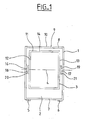
- a machine comprises a frame 1 forming an enclosure 2 and a drum 3 of generally cylindrical shape located in the enclosure 2.
- the drum 3 is rotatably mounted relative to the frame 1 along its axis 4.
- the frame 1 rests on the ground by via feet 5, 6, two of which are visible in FIG. 1, feet 5, 6 being located on a lower wall 7 of the frame 1, outside the enclosure 2.
- the frame 1 comprises an upper wall 8, provided with an opening 9 which can be closed at using an access door 10. Opening door 10 gives access to the drum 3.
- the drum 3 comprises a cylindrical wall 11 and two radial walls end 12, 13, axially closing the drum 3.
- the cylindrical wall 11 can be provided with axial reinforcements to increase its rigidity.
- the cylindrical wall 11 can be perforated, as in washing machines, to allow the passage of water between the inside and outside of the drum 3.
- the cylindrical wall 3 is provided with an opening 14.
- the opening 14 is located opposite the opening 8 of the frame 1 when the drum 3 is in a position angular determined.
- the opening 14 of the drum 3 can be closed in a known manner by an articulated flap, possibly perforated, not shown in Figure 1.
- the drum 3 is rotatably mounted on the frame 1 by means of supports 16, 17, axially fixed on either side of the drum 3.
- the supports 16, 17 comprise each a cylindrical seat 18, 19, allowing the fixing of the drum supports 16, 17 by means of rolling bearings 20, 21.
- the support 16 comprises a flange 23 fixed to the radial wall 12, for example by means of screws, not shown in FIG. 2.
- the support 16 comprises an axis 24, coaxial with the drum 3, and extending from a central zone of the flange 23, on the side opposite to the drum 3.
- the axis 24 is provided at its free end of a cylindrical seat 25, of smaller diameter forming a radial shoulder 26.
- the machine For mounting the drum 3 on the frame 1, the machine includes a bearing instrumented bearing 27, which includes an inner rotating ring 28, provided on an outer surface 28a of a toroidal raceway 29, and a ring non-rotating outer 30, provided on a bore 30a with a raceway toroidal 31.
- the rolling bearing 27 comprises rolling elements 32, here balls, arranged between the toroidal raceways 29, 31 of the inner rings 28 and outer 30, held circumferentially spaced apart by a cage 33.
- the inner ring 28 includes radial side faces 28b, 28c and a bore 28d.
- the outer ring 30 includes radial lateral faces 30b, 30c, located in the same plane respectively as the radial lateral faces 28b, 28c of the inner ring 28, and a cylindrical outer surface 30d.
- the outer ring 30 comprises, on its bore 30a, an annular groove 34 located near the lateral face 30b.
- the outer ring 30 includes a second annular groove 35 located near the side face 30c of the outer ring 30, being symmetrical of the first groove 33 relative to the radial plane passing through the center rolling elements 32.
- a seal 36 comprising a metal frame 37 and a elastic part 38 molded onto the metal frame 37 is disposed between the inner 28 and outer 30 rings.
- the elastic part 38 is made of material synthetic and comprises a bead 39a projecting into the groove 35, from the larger diameter area of the elastic part 38, and a lip 39b coming in friction contact with the outer surface 28a of the inner ring 28, from of the area of smaller diameter of the elastic part 38.
- a sensor assembly 40 which will be described in more detail below, is fixed to the rolling bearing 27, on the side opposite the sealing member 36.
- the rolling bearing 27 is adjusted to the surface 25 of the axis 24 of the support 16.
- the bore 28d of the inner ring 28 comes into contact with the bearing cylindrical 25.
- the rolling bearing 27 is introduced on the cylindrical bearing surface 25 until the lateral face 28c of the inner ring 28 comes into contact with the shoulder 26 of the axis 24.
- the cylindrical seat 25 has a diameter substantially equal to the diameter of the bore 28d of the inner ring 28.
- the axis 24 has an outer diameter greater than the diameter of the bore 28d of the ring inner 28, while being less than the diameter of the outer surface 28a of the inner ring 28.
- the cylindrical seat 25 extends over an axial length less than the axial length of the inner ring 28.
- the free end of the axis 24 is provided with a central threaded hole 24a.
- a screw 41 comprising a threaded rod 42 is introduced into the threaded hole 24a of the axis 24 and a screw head 43.
- a washer 44 is disposed between the screw head 43 and the face side 28b of the inner ring 28. The screw 41 is tightened so that the washer 44 either pressed axially against the lateral face 28b of the inner ring 28, so to maintain the rolling bearing 27 on the cylindrical surface 25.
- the outer ring 30 is fixed to the frame 1 in a housing 45, in the form general cup, formed by a radial portion 46, a tubular casing 47 extending axially towards the drum 3 from the radial portion 46, and a flange radial 48 extending inwards from the free edge of the tubular casing 47.
- the free edge of the radial rim 48 is curved to extend obliquely inward and toward the drum 3.
- the outer ring 30 is adjusted in the housing 45 coming into contact through its outer surface 30d with a bore 47a of the tubular casing 47, the lateral face 30c of the outer ring 30 coming in contact with the surface 48a of the radial rim 48 opposite the drum 3.
- the free edge 48b of the radial rim 48 has an inner diameter greater than the diameter of the axis 25, to allow the passage of the axis 25.
- the tubular casing 47 has a length less than the axial length of the outer ring 30, so that the radial portion 46 is located axially between the lateral surfaces 30b, 30c of the ring outer 30, being adjacent to the lateral face 30b opposite the radial rim 48.
- the sensor assembly 40 comprises a sensor block 50 comprising a support 51 which comprises an annular body 52 of external radius substantially equal to the radius of the bore 30a of the outer ring 30, and an inner diameter between the diameter of the bore 30a of the outer ring 30 and the diameter of the surface outer 28a of the inner ring 28.
- the body 52 includes an axial end 52a projecting in space between the inner 28 and outer 30 rings.
- the body 52 includes a annular radial projection 53 extending outwardly from the exterior surface of the end 52a in the groove 34.
- the projection 53 is in shape agreement with the groove 34 into which it is introduced.
- the projection 53 allows the fixing of the body 52 on the outer ring 30 by radial interference.
- a radial flange 55 extends outward from the end of the body 52 opposite the end 52a.
- the radial flange 55 forms a radial surface 55a in contact with the lateral face 30b of the outer ring 30.
- a magnet 57 is embedded in the body 52 by being flush with a radial surface 58 opposite the elements wheels 32.
- the sensor block 50 carries a card 59 in contact with the radial surface 58 and carrying a detection member 60, here a magnetosensitive sensor, located axially opposite the magnet 57.
- the card 59 comprises a radial projection 59a provided with invisible electrical connection means, for the transmission of measurement signals emitted by the detection member 60 to processing means apart.
- the electrical connection means can be plugs or conductive tabs.
- the card 59 can be a printed circuit board.
- the sensor assembly also includes a cover 61 comprising a crown 62 with square section of which a lateral face 62a comes into contact with the flange 55 on the side opposite to the outer ring 30.
- the crown 62 comprises a notch allowing the passage of the radial projection 59a of the card 59.
- the cover 61 also includes a tooth 63 projecting axially from a portion of the face lateral 62a of the crown 62, and coming in a corresponding notch 56 of the flange 55 of the body 52.
- the cover 61 comprises a radial portion 64 extending inwards from the crown 62 while being axially spaced from the body 52. The free edge of the radial portion 64 has a diameter substantially equal to the diameter of the outer surface 28a of the inner ring 28.
- the collar 55 of the sensor unit 50 and the cover 61 include radial extensions 55c, 61c located opposite and surrounding the radial projection 59a of card 59 to form a housing capable of receiving an electrical connection socket with remote processing facilities.
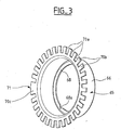
- the sensor assembly also includes a shaped encoder wheel 65 general cup.
- the encoder wheel 65 comprises a cylindrical part 66 of which an axial end is internally folded back axially in the opposite direction by forming an inner cylindrical surface 67, then radially inwardly forming a radial rim 68.
- the internal cylindrical bearing surface 67 is fitted on the outer surface 28a of the inner ring 28 until the radial flange 68 comes into contact with the lateral face 28b of the inner ring 28.
- the encoder wheel 65 includes a radial portion extending outward from the end la cylindrical part 66 opposite the inner ring 28.
- the radial portion 69 is located axially between the radial portion 64 of the cover 61 and the detection member 60 fixed on the card 59.
- the free edge of the radial wall 69 includes an alternation circumferential notches 70a and tabs 70b.
- the encoder wheel 65 is made of ferromagnetic material.
- the scrolling of tabs 70a and notches 70b cause variations in the magnetic field produced by the magnet 57.
- the detection member 60 detects the field variations magnetic caused by the scrolling of the notches 70a and the tabs 70b.
- the radial flange 68 of the wheel encoder 65 includes a notch 68a for angular indexing of the encoder wheel 65 forming a visual assembly mark for the angular orientation of the encoder wheel 65 with respect to the drum 3.
- the coding wheel 65 also comprises on its part active located opposite the detection member 60 an angular reference zone 71 in the alternation of the notches 70a and the tabs 70b.
- the reference area angular 71 is here achieved by the absence of a notch, so that there is a tongue 70c wider than the others which causes the organ to emit detection 60 of a particular pulse in a signal emitted by the detection 60 during movement of the encoder wheel 65 opposite said member of detection 65.
- the sensor assembly also includes a temperature 72 embedded in the body 52, more particularly in the end 52a of the body 52 located between the inner 28 and outer 30 rings.
- the notch indexing 68a is in the same axial plane as an indexing mark 73 formed on the end of the axis 24.
- the reference 73 allows an angular orientation of the encoder wheel 65 relative to the axis 24 and therefore to the drum 3, during assembly of the rolling bearing on axis 24.
- the indexing means of the coding wheel 65 make it possible to know, thanks to the instrumented roller bearing sensor assembly, the position of the drum 3.
- the notch 68a forms a visual reference for mounting the inner ring 28 provided of the coding wheel 65 on the axis 24 provided with its visual reference 73.
- the wheel coder 65, and the angular reference zone 71 of the coding wheel 65 are indexed angularly with respect to the drum 3.
- the radial rim 64 of the cover 61 has an internal diameter greater than the diameter of the outer surface 28a of the inner ring 28.
- the radial flange 64 does not not visually hide the radial rim 68 of the encoder wheel 65, thus allowing see the notch 68a and the end of the axis 24 when mounting the rolling bearing on the axis 24.
- the coding wheel 65 can be angularly oriented relative to the axis 24, the rolling bearing already being fully assembled.
- the sensor assembly also includes an electrostatic brush 75 under the form of a blade 76 secured by one end of a fixed part of the assembly sensor, and rubbing its other end on a rotating part 69 of the bearing with instrumented bearing 27.
- the blade 76 comprises an end situated between the crown 62 of cover 61 while being fixed on card 59, and being connected electrically to the electrical connection means of the card 59, the end opposite of the blade 76 rubbing against an internal face of the radial wall 69 of the encoder wheel 65 oriented on the side of the sensor unit 50.
- the blade 76 is curved, elastically deformable and axially prestressed to ensure contact permanent with the radial wall 69.
- the electrostatic brush 75 is located axially between the encoder wheel 65 and the card 59 supporting the detection member 60.
- the brush electrostatic 75 is therefore located in the air gap of the sensor assembly.
- the broom 75 is angularly offset from the detection member 60 to keep the axial compactness of the sensor assembly, and to prevent the brush 75 from disturbing the measurements made by the magnetosensitive sensor 60.
- the brush 75 comes into contact on the internal face of the portion a continuous portion of the radial portion 69, of so as not to create vibration, and to avoid premature wear of the elements.
- the brush 75 could come into contact with a portion continuous from the external face of the radial wall 69 of the coding wheel 65 oriented towards the side opposite to sensor block 50.
- the electrostatic charges are evacuated by the electrical connection circuit of the card 59.
- the electrostatic brush 75 can be disposed between the block sensor 50, more precisely the card 59, and the rotating inner ring 28.
- the drum 3 When mounting the drum, the drum 3 is simply mounted to rotate via the rolling bearing, which already includes a set of drum rotation parameters 3.
- the assembly of the drum 3 is simple and requires a limited number of mounting operations.
- the orientation of the drum is known by means of indexing rolling bearing.
- the drum 3 rotation parameters sensor assembly and the brush electrostatic are arranged on the side of the rolling bearing opposite the drum 3.
- the sealing member 36 prevents the passage of external elements or liquid from the enclosure 2 where the drum 3 is located towards the opposite side of the radial portion 46 of the housing 45.
- the sensor assembly comprising the detection member, the magnet, the card, connection means, temperature sensor and brush 75 are protected because the seal 36 prevents the passage of water to the side of the bearing to bearing 27 opposite the drum 3.
- the temperature sensor 72 is all the more protected that it is embedded in the sensor block 52. This position of the detection means temperature nevertheless allows to know the temperature prevailing in the enclosure 2, by thermal conduction.
- the mounting of the drum 3 by means of a rolling bearing instrumented allows to know the rotation parameters of the drum 3 as the position, speed and / or angular acceleration of the drum 3. These can be used parameters of rotation of the drum 3 to know, and in particular the acceleration angle of the drum 3, to detect an imbalance in the machine due to a bad distribution of the load in the drum 3, as may be the case for a drum full of laundry. We can then achieve a balancing of the drum, for example using the drum rotation control 3.
- a machine is obtained provided with a drum, the mounting is simple and can be done by a limited number of operations, and using of a limited number of items.
- the mounting of the drum via a Instrumented rolling bearing allows combined guidance functions in drum rotation and detection of the drum rotation parameters, and limit the number of mounting operations. Furthermore, we obtain a set of assembly of the compact drum and protected from attack by elements or liquid filling the drum.
Landscapes
- Engineering & Computer Science (AREA)
- Textile Engineering (AREA)
- Physics & Mathematics (AREA)
- General Physics & Mathematics (AREA)
- General Engineering & Computer Science (AREA)
- Mechanical Engineering (AREA)
- Control Of Washing Machine And Dryer (AREA)
Abstract
Description
- la figure 1 est une vue en coupe d'une machine à tambour, selon l'invention ;
- la figure 2 est une vue de détail en coupe axiale du montage du tambour de la machine selon la figure 1 ;
- la figure 3 est une vue en perspective d'une roue codeuse d'un palier à roulement instrumenté ; et
- la figure 4 est une demi-vue en coupe d'un palier à roulement instrumenté utilisé pour le montage d'un tambour d'une machine, selon un aspect de l'invention.
Claims (11)
- Machine comprenant un bâti (1), un tambour (3) monté en rotation sur le bâti et une porte d'accès au tambour, caractérisé par le fait que le tambour est monté à rotation par l'intermédiaire d'un palier à roulement instrumenté (27) pourvu d'un ensemble capteur de paramètres de rotation du tambour (40).
- Machine selon la revendication 1, caractérisé par le fait que le palier à roulement instrumenté (27) comprend des moyens d'indexation angulaire (71, 68a) de la position du tambour (3).
- Machine selon l'une quelconque des revendications 1 ou 2, caractérisé par le fait que le tambour (3) comprend une ouverture (14) formée dans une paroi cylindrique.
- Machine selon l'une quelconque des revendications précédentes, caractérisé par le fait que le palier à roulement instrumenté comprend une liaison électrique (75) entre des éléments conducteurs associés respectivement au tambour (3) et au bâti (1).
- Machine selon l'une quelconque des revendications précédentes, caractérisé par le fait que la liaison électrique (75) comprend une lame conductrice (76) solidaire par une extrémité d'une partie fixe (59) de l'ensemble capteur, et venant frotter pas son autre extrémité sur une partie tournante (69) du palier à roulement instrumenté (27).
- Machine selon l'une quelconque des revendications 1 à 5, caractérisé par le fait que la liaison électrique (75) est disposée entre un bloc capteur (50) et une roue codeuse conductrice (65).
- Machine selon l'une quelconque des revendications 1 à 5, caractérisé par le fait que la liaison électrique est disposée entre un bloc capteur (50) et une bague tournante du palier à roulement (28).
- Machine selon l'une quelconque des revendications précédentes, caractérisé par le fait que le palier à roulement instrumenté comprend des moyens de détection de température (72).
- Machine selon la revendication 8, caractérisé par le fait que les moyens de détection de température (72) sont supportés par un bloc capteur (50) de l'ensemble capteur (40).
- Machine selon l'une quelconque des revendications précédentes, caractérisé par le fait qu'un bloc capteur (50) de l'ensemble capteur (40) est disposé d'un côté du palier à roulement (27) opposé au tambour (3).
- Machine selon l'une quelconque des revendications précédentes, caractérisé par le fait que la palier à roulement instrumenté comprend une bague tournante (28), une bague non tournante (30), des éléments roulants (32), et un ensemble capteur comprenant un bloc capteur (50) fixé sur la bague non tournante (30) et une roue codeuse (65) fixée sur la bague tournante (28).
Applications Claiming Priority (2)
| Application Number | Priority Date | Filing Date | Title |
|---|---|---|---|
| FR0201447 | 2002-02-06 | ||
| FR0201447A FR2835542B1 (fr) | 2002-02-06 | 2002-02-06 | Machine a tambour equipee d'un ensemble capteur de parametres de rotation du tambour |
Publications (3)
| Publication Number | Publication Date |
|---|---|
| EP1335059A1 true EP1335059A1 (fr) | 2003-08-13 |
| EP1335059B1 EP1335059B1 (fr) | 2006-11-15 |
| EP1335059B9 EP1335059B9 (fr) | 2008-02-13 |
Family
ID=27589600
Family Applications (1)
| Application Number | Title | Priority Date | Filing Date |
|---|---|---|---|
| EP03290277A Expired - Lifetime EP1335059B9 (fr) | 2002-02-06 | 2003-02-04 | Machine à tambour équipée d'un ensemble capteur de paramètres de rotation du tambour |
Country Status (3)
| Country | Link |
|---|---|
| EP (1) | EP1335059B9 (fr) |
| DE (1) | DE60309610T2 (fr) |
| FR (1) | FR2835542B1 (fr) |
Cited By (3)
| Publication number | Priority date | Publication date | Assignee | Title |
|---|---|---|---|---|
| FR2854443A1 (fr) * | 2003-05-02 | 2004-11-05 | Skf Ab | Dispositif de roulement instrumente |
| RU2418120C2 (ru) * | 2007-01-08 | 2011-05-10 | Электролюкс Хоум Продактс Корпорейшн Н.В. | Устройство определения углового положения барабана стиральной машины |
| WO2021152082A1 (fr) | 2020-01-30 | 2021-08-05 | Ntn-Snr Roulements | Palier instrumente integrant un collecteur de courant de fuite et un blindage magnetique |
Families Citing this family (1)
| Publication number | Priority date | Publication date | Assignee | Title |
|---|---|---|---|---|
| CN109610129B (zh) * | 2018-12-06 | 2022-03-25 | 无锡小天鹅电器有限公司 | 衣物处理装置 |
Citations (4)
| Publication number | Priority date | Publication date | Assignee | Title |
|---|---|---|---|---|
| DE2151542A1 (de) * | 1971-10-15 | 1973-04-19 | Siemens Ag | Fluidischer signalgeber zur positionierung eines auf einer fuehrung bewegten objektes |
| FR2196542A1 (fr) * | 1972-08-16 | 1974-03-15 | British Domestic Appliances | |
| FR2784402A1 (fr) * | 1998-10-09 | 2000-04-14 | Elbi Int Spa | Dispositif de capteur de position pour panier de machine a laver le linge |
| EP1037051A1 (fr) * | 1999-03-17 | 2000-09-20 | Skf France | Palier à roulement instrumenté |
-
2002
- 2002-02-06 FR FR0201447A patent/FR2835542B1/fr not_active Expired - Fee Related
-
2003
- 2003-02-04 EP EP03290277A patent/EP1335059B9/fr not_active Expired - Lifetime
- 2003-02-04 DE DE60309610T patent/DE60309610T2/de not_active Expired - Fee Related
Patent Citations (4)
| Publication number | Priority date | Publication date | Assignee | Title |
|---|---|---|---|---|
| DE2151542A1 (de) * | 1971-10-15 | 1973-04-19 | Siemens Ag | Fluidischer signalgeber zur positionierung eines auf einer fuehrung bewegten objektes |
| FR2196542A1 (fr) * | 1972-08-16 | 1974-03-15 | British Domestic Appliances | |
| FR2784402A1 (fr) * | 1998-10-09 | 2000-04-14 | Elbi Int Spa | Dispositif de capteur de position pour panier de machine a laver le linge |
| EP1037051A1 (fr) * | 1999-03-17 | 2000-09-20 | Skf France | Palier à roulement instrumenté |
Cited By (5)
| Publication number | Priority date | Publication date | Assignee | Title |
|---|---|---|---|---|
| FR2854443A1 (fr) * | 2003-05-02 | 2004-11-05 | Skf Ab | Dispositif de roulement instrumente |
| RU2418120C2 (ru) * | 2007-01-08 | 2011-05-10 | Электролюкс Хоум Продактс Корпорейшн Н.В. | Устройство определения углового положения барабана стиральной машины |
| WO2021152082A1 (fr) | 2020-01-30 | 2021-08-05 | Ntn-Snr Roulements | Palier instrumente integrant un collecteur de courant de fuite et un blindage magnetique |
| FR3106869A1 (fr) | 2020-01-30 | 2021-08-06 | Ntn-Snr Roulements | Palier instrumenté intégrant un collecteur de courant de fuite et un blindage magnétique |
| US12152637B2 (en) | 2020-01-30 | 2024-11-26 | Ntn-Snr Roulements | Instrumented bearing incorporating a leakage current collector and a magnetic shield |
Also Published As
| Publication number | Publication date |
|---|---|
| DE60309610T2 (de) | 2007-09-06 |
| FR2835542A1 (fr) | 2003-08-08 |
| EP1335059B1 (fr) | 2006-11-15 |
| DE60309610D1 (de) | 2006-12-28 |
| FR2835542B1 (fr) | 2004-07-02 |
| EP1335059B9 (fr) | 2008-02-13 |
Similar Documents
| Publication | Publication Date | Title |
|---|---|---|
| EP0454547B1 (fr) | Moyeu à roulement équipé d'un dispositif de détection de la vitesse de rotation | |
| EP0521789B1 (fr) | Ensemble capteur étanche intégrable dans un roulement à capteur d'informations et roulement équipé d'un tel ensemble | |
| EP1470428A1 (fr) | Support de fixation, palier a roulement et procede de montage associes | |
| EP0026018B1 (fr) | Machine à laver et à essorer le linge à entraînement du tambour par courroie immergée | |
| EP0726468A1 (fr) | Dispositif de codeur pour capteur de vitesse de rotation et roulement équipé d'un tel dispositif | |
| FR2645276A1 (fr) | Capteur de la vitesse des roues d'un vehicule pour un essieu-moteur | |
| FR2618516A1 (fr) | Ensemble d'etancheite a interposer entre deux organes en rotation relative, apte a permettre la detection de la rotation relative entre eux et palier pour supporter une roue de vehicule pourvu de celui-ci | |
| EP0616219A1 (fr) | Ensemble comportant joint d'étanchéité et capteur de vitesse | |
| FR2684114A1 (fr) | Cuve en plastique perfectionnee, pour lave-linge. | |
| EP1366370B1 (fr) | Dispositif de galet a roulement instrumente | |
| FR2631664A1 (fr) | Montage de moyeu de roue non motrice de vehicule equipe d'un dispositif a pulseur et capteur pour mesure de la vitesse de rotation de la roue | |
| FR2626631A1 (fr) | Montage de palier a roulement avec dispositif capteur | |
| FR2718805A1 (fr) | Organe de retenue axiale d'un roulement à capteur d'informations et montage de roulement comportant un tel organe. | |
| EP1335059B9 (fr) | Machine à tambour équipée d'un ensemble capteur de paramètres de rotation du tambour | |
| FR2695179A1 (fr) | Machine ayant une source de vibrations. | |
| EP0549467B1 (fr) | Système de commande d'arrêt d'un appareil sèche-linge | |
| FR2784402A1 (fr) | Dispositif de capteur de position pour panier de machine a laver le linge | |
| EP3256754A1 (fr) | Dispositif d'equilibrage pour une machine a tambour rotatif et machine comprenant un tambour rotatif equipe d'un tel dispositif | |
| KR950014942B1 (ko) | 회전축의 회전 파라미터들을 측정하는 장치 | |
| FR3114197A1 (fr) | Rotor pour moteur électrique équipé d'un circuit électronique | |
| EP1842950A1 (fr) | Dispositif de palier pour une machine à laver et / ou sécher le linge | |
| FR2782970A1 (fr) | Dispositif de volant de manoeuvre | |
| FR2823812A1 (fr) | Dispositif d'etancheite pour palier a roulement instrumente et palier a roulement instrumente | |
| FR3112373A1 (fr) | Motoréducteur à enveloppe cylindrique et moteur tubulaire correspondant. | |
| FR2792067A1 (fr) | Capteur de mesure sans contact de la rotation d'un rotor dans un debimetre de liquide |
Legal Events
| Date | Code | Title | Description |
|---|---|---|---|
| PUAI | Public reference made under article 153(3) epc to a published international application that has entered the european phase |
Free format text: ORIGINAL CODE: 0009012 |
|
| AK | Designated contracting states |
Designated state(s): AT BE BG CH CY CZ DE DK EE ES FI FR GB GR HU IE IT LI LU MC NL PT SE SI SK TR |
|
| AX | Request for extension of the european patent |
Extension state: AL LT LV MK RO |
|
| RIN1 | Information on inventor provided before grant (corrected) |
Inventor name: NIARFEIX, FRANEOIS |
|
| 17P | Request for examination filed |
Effective date: 20031218 |
|
| AKX | Designation fees paid |
Designated state(s): DE FR IT |
|
| GRAP | Despatch of communication of intention to grant a patent |
Free format text: ORIGINAL CODE: EPIDOSNIGR1 |
|
| GRAS | Grant fee paid |
Free format text: ORIGINAL CODE: EPIDOSNIGR3 |
|
| GRAA | (expected) grant |
Free format text: ORIGINAL CODE: 0009210 |
|
| AK | Designated contracting states |
Kind code of ref document: B1 Designated state(s): DE FR IT |
|
| REF | Corresponds to: |
Ref document number: 60309610 Country of ref document: DE Date of ref document: 20061228 Kind code of ref document: P |
|
| PLBE | No opposition filed within time limit |
Free format text: ORIGINAL CODE: 0009261 |
|
| STAA | Information on the status of an ep patent application or granted ep patent |
Free format text: STATUS: NO OPPOSITION FILED WITHIN TIME LIMIT |
|
| 26N | No opposition filed |
Effective date: 20070817 |
|
| PGFP | Annual fee paid to national office [announced via postgrant information from national office to epo] |
Ref country code: IT Payment date: 20080226 Year of fee payment: 6 |
|
| PGFP | Annual fee paid to national office [announced via postgrant information from national office to epo] |
Ref country code: FR Payment date: 20080218 Year of fee payment: 6 Ref country code: DE Payment date: 20080331 Year of fee payment: 6 |
|
| REG | Reference to a national code |
Ref country code: FR Ref legal event code: ST Effective date: 20091030 |
|
| PG25 | Lapsed in a contracting state [announced via postgrant information from national office to epo] |
Ref country code: DE Free format text: LAPSE BECAUSE OF NON-PAYMENT OF DUE FEES Effective date: 20090901 |
|
| PG25 | Lapsed in a contracting state [announced via postgrant information from national office to epo] |
Ref country code: FR Free format text: LAPSE BECAUSE OF NON-PAYMENT OF DUE FEES Effective date: 20090302 |
|
| PG25 | Lapsed in a contracting state [announced via postgrant information from national office to epo] |
Ref country code: IT Free format text: LAPSE BECAUSE OF NON-PAYMENT OF DUE FEES Effective date: 20090204 |