EP1334953A2 - Method and apparatus for severing sheets of glass - Google Patents
Method and apparatus for severing sheets of glass Download PDFInfo
- Publication number
- EP1334953A2 EP1334953A2 EP02026809A EP02026809A EP1334953A2 EP 1334953 A2 EP1334953 A2 EP 1334953A2 EP 02026809 A EP02026809 A EP 02026809A EP 02026809 A EP02026809 A EP 02026809A EP 1334953 A2 EP1334953 A2 EP 1334953A2
- Authority
- EP
- European Patent Office
- Prior art keywords
- load
- glass
- threshold
- cutting
- increase
- Prior art date
- Legal status (The legal status is an assumption and is not a legal conclusion. Google has not performed a legal analysis and makes no representation as to the accuracy of the status listed.)
- Granted
Links
Images


Classifications
-
- C—CHEMISTRY; METALLURGY
- C03—GLASS; MINERAL OR SLAG WOOL
- C03B—MANUFACTURE, SHAPING, OR SUPPLEMENTARY PROCESSES
- C03B33/00—Severing cooled glass
- C03B33/02—Cutting or splitting sheet glass or ribbons; Apparatus or machines therefor
- C03B33/023—Cutting or splitting sheet glass or ribbons; Apparatus or machines therefor the sheet or ribbon being in a horizontal position
- C03B33/033—Apparatus for opening score lines in glass sheets
-
- B—PERFORMING OPERATIONS; TRANSPORTING
- B65—CONVEYING; PACKING; STORING; HANDLING THIN OR FILAMENTARY MATERIAL
- B65G—TRANSPORT OR STORAGE DEVICES, e.g. CONVEYORS FOR LOADING OR TIPPING, SHOP CONVEYOR SYSTEMS OR PNEUMATIC TUBE CONVEYORS
- B65G2249/00—Aspects relating to conveying systems for the manufacture of fragile sheets
- B65G2249/04—Arrangements of vacuum systems or suction cups
Definitions
- the invention relates to a method for breaking glass plates according to the preamble of claim 1 and a device for Carrying out the method according to the preamble of claim 26.
- the breaking edge runs irregular.
- the breaking edge in the longitudinal direction not straight, but more or less wavy.
- the breaking edge does not run as desired perpendicular to the glass surface but at an oblique angle.
- so-called side cracks arise, which more or less run parallel to the main breaking edge, from which e.g. in particular mussel or scaly fracture results.
- Microcracks develop that cross into the main break into the glass to run; these result in the further processing of a broken one Glass pane to break.
- thermal Loads such as in the installation of glass panes in winter gardens, such edges cause problems.
- glass for furniture construction glass for motor vehicles or glass in construction or Interior construction leads to the formation of the edges that the edges have to be sanded after breaking. Therefor the glass panels must be made with an oversize from the outset are and then become very complex to the final dimension abraded.
- the object of the invention is a method and an apparatus for breaking glass plates that provide a clean, result in a flawless edge.
- the method according to the invention provides the effect of the so-called slow crack formation when breaking glass.
- This slow crack propagation can be at the bottom of a scratch mark take place in the glass.
- a slow crack propagation from a certain load level can take place in a controlled manner if at least after the Reach this load level depending on the glass thickness certain increase in the load entry is observed.
- the required breaking load is caused, for example, by the bulging applied to the glass plate.
- To measure or control the load can both the one initiated by the bulge Force can be measured or regulated directly, or indirectly via the height or strength of the curvature can be determined.
- the breaking load F crit. And / or, if the curvature or deformation rate is set, the time until the break T crit. And / or the strength of the curvature or deformation necessary for the fracture is determined to determine the load height necessary for the slow crack propagation . that means the way to the break S crit .
- the load level that is at least necessary for slow crack propagation is then determined.
- This threshold value T s , F s or S s is approximately 70 to 80% of the breaking load.
- a load increase rate is set which is still so low that the slow crack propagation takes place. It is then very easy to determine from the respective fracture patterns whether slow crack propagation has taken place, since smooth fracture edges are then present.
- the rate of load increase depends on the glass thickness. According to the invention, the breaking of the glass takes place in a linear manner Load increase over time so slowly that the slow crack propagation is guaranteed. To break up too accelerate, according to the invention, until the load threshold is reached the load increase can be done relatively quickly, in particular at a speed customary in the prior art and only after that necessary for slow crack propagation Threshold or a corresponding threshold range Rate of load increase to form a slow crack propagation be lowered. To the load increase rate itself effectively reducing glass thickness by deepening the crack adapt, the rate of load increase can also be continuous be reduced or increased.
- the device according to the invention has one or more Crushing bars and / or suction cups or the like, which are especially electric be lifted away or force controlled so that everyone time the force entered in the glass plate is known and controllable is.
- To the bending moment which is in the range of Scoring line is introduced to define and control hold-down devices and / or suction cups can be used, which act on both sides of the glass next to the scratch line.
- the glass plate or glass panel To break a glass plate or glass sheet 1, the glass plate or glass panel first in the conventional manner in the area the desired dividing line with a cutting wheel or other suitable means scratched and thereby along a scratch line the desired dividing line. Then will move the glass plate or glass sheet into a breaking device. In order to break the glass plate or glass sheet, becomes the glass plate or glass sheet in the area of the scratch line - especially towards the scoring line - arched, or by folding down a table area or other suitable means or Methods of breakage brought about.
- the breaking load F crit At which a certain glass plate of a predetermined thickness breaks along the scratch line previously applied with a certain cutting wheel, the glass plate is subjected to a load (force) and a specific load increase rate (FIG. 25a).
- the load increase rate that is to say the increase in the load per time, corresponds, for example, to the load increase rates which are customary in the prior art and which are very high. A slow crack propagation is not possible with these high load increase rates. According to the invention, it was recognized that the fracture resulting from a controlled, continuous, slow crack propagation resulted in clean, straight and perpendicular fracture edges.
- a minimum load level or a load threshold F s is necessary for a controlled and technically usable slow crack propagation.
- a load increase rate is set at least above this load threshold F s , at which a controlled, continuous, slow crack propagation takes place depending on, among other things, the thickness of the glass. As the glass thickness increases, lower load increase rates are usually necessary (Fig. 25f).
- the load threshold F s is usually around 70 to 80% of the breaking load. Like the appropriate rate of increase in load, it should preferably be determined empirically for each type and thickness of glass and may also deviate from the stated value. In the simplest case (FIG.
- a uniform load increase rate can be selected which corresponds to the load increase rate above the load threshold F s suitable for slow crack propagation.
- the load increase rate can be chosen to be very high until the load threshold F s is reached and only after the threshold load has been reached can the course of the load increase rate favorable for the slow crack formation be assumed (FIG. 25c).
- the area before the threshold load F s is reached is essentially uncritical with regard to the rate of increase in load, so that time can also be saved in this area by a very high rate of increase in load.
- the transitions of the different load increase rates do not have to be abrupt here, rather they can transition smoothly (FIGS. 25d, 25e).
- the load increase rate above the load threshold F s can be such that it is adapted to the crack propagation.
- the effective glass thickness that is to say the glass thickness between the crack base and the glass surface opposite the scratch line. Since there is a connection between the load increase rate which is favorable for the formation of the slow crack propagation and the glass thickness, the load increase rate can be adapted to the effective glass thickness.
- the rate of load increase can be reduced over time (Fig. 25d) or increased (Fig. 25g), which is determined empirically in particular.
- the load increase rates can flow smoothly into one another (Fig. 25h).
- a water-based cutting fluid is advantageously used, in particular aqueous emulsions or suspensions.
- the slow crack propagation is particularly well designed and easy to control, the range between the required load threshold F s and the breaking load on the one hand and the range of favorable load increase rates on the other hand being relatively large.
- the influencing variables on the target variable load threshold F s and load increase rate determined empirically for the above-mentioned and possibly further parameters can be stored in particular as data for a machine control.
- the parameters for the operation of a device operating according to the method according to the invention can be recorded manually or automatically and the device can be controlled accordingly. If necessary, a readjustment can be made after the assessment of a fracture pattern.
- a typical fracture pattern shows an area that has been created by scoring, a clean, smooth area and - if slow crack propagation according to the invention has not taken place - possibly also an area that shows a high-energy, unclean fracture.
- the breaking load F crit In order to determine a favorable load threshold F s , the breaking load F crit. Is determined, as already stated. Subsequently, the load is increased up to the load threshold with a relatively high load increase rate, particularly in the state of the art.
- the load threshold F s is first crit in the range between 70 and 80% of the breaking load F. Specified, since usually show good results in such a load height. In a subsequent experiment, once this defined load threshold F s has been reached, the load is increased at a rate of increase in load which, based on experience, is relatively low, but is significantly lower than the rate of increase in load until the load threshold is reached.
- the rate of increase in load is determined in particular over the time which lies between reaching the load threshold F s and breaking (reaching breaking load F crit. ) (FIG. 25f).
- T d T fs (1 + ⁇ d d 0 ) calculated, where T d is the time from reaching the load threshold to breakage, d the glass thickness, d 0 is a reference glass thickness, T Fs is the time to reach the load threshold and ⁇ is a difficulty factor, which is determined by the above parameters.
- the reference glass thickness is usually between 1 and 4 mm.
- the break edges are analyzed. If the breaklines show the desired optimized breakline, a correction is not necessary. If, particularly in the last section of the break, there are signs of an energy-rich mussel break, the load threshold can be changed, in particular lowered and / or the time T d can be extended, which corresponds to a decrease in the rate of increase in load.
- the break shows an optimal course, it can accelerate of the entire crushing process, the load increase rate and / or the Load threshold can be increased until the break is again mussel, shows non-optimized areas. This allows the area to be limited or delimited by slow crack propagation is safely achievable.
- a holding phase (FIGS. 25i to 25p) is advantageous if the voltage prevailing in the glass due to the load input is to be homogenized.
- the load increase up to the break occurs in three phases; a load increase phase 1 at least until the load threshold F s or above is reached, a load holding phase II and then a load increase phase III until breakage (FIGS. 25i to 25p, only roughly schematic and not quantitative representation).
- the load increase rate can be reached until the load threshold is reached be high to very high.
- the hereby entered Tensions can be initiated during the load holding phase and continued slow crack propagation upon homogenization the stress is relieved especially over the crack length become.
- the load increase phase III there is a load increase rate chosen, which ensures the further slow crack propagation.
- the load increase rates linear (Fig. 25i) or non-linear (Fig. 25j to 25p), with abrupt (Fig. 25i) and flowing transitions (Fig. 25j to 251) are possible.
- a high load input which is above the load threshold F s can also be undertaken initially for crack initialization and a subsequent relief (relaxation phase II) can be provided during phase II.
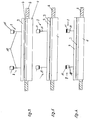
- the device 1 according to the invention (FIGS. 1 to 24) has one Processing table 2 for placing glass plates or glass panels Third
- the breaking bar 4 is an elongated one Body in the form of a bar or a bar.
- the crowbar 4 is in a slot-shaped recess 5 in the processing table 2 arranged.
- the recess 5 extends transversely for the longitudinal extension of the processing table 2 and is preferred shorter than the table width but longer than the width a placed glass plate 3.
- the breaking bar 4 has one or several drives 6, which have a linkage 7, in particular a spindle 7 each act on the crowbar 4 in such a way that the breaker bar 4 can be moved up out of the slot and can be driven in again.
- the hold-down devices 8 each have a hold-down bar 9.
- the hold-down bars 9 are elongated and run parallel to the recess 5, being a length have, which corresponds approximately to the length of the crowbar 4.
- the hold-down bars 9 are connected via a linkage 10 or the like.
- Reset devices 11 connected such that the hold-down bars 9 from a lower rest position against the force of the reset devices 11 can be raised until end stops are reached are.
- the reset devices 11 are, for example Spring assemblies or gas pressure springs.
- the hold-down devices 9 can be made closer to each other by reducing their distance drive and vice versa, with each hold-down bar 9 closer to the breaker bar is moved and vice versa.
- FIG. 10 to 13 are adjacent to the recess 5 and along the recess 5 suction devices 15 available.
- the suction device 15 includes in particular round suction cups 16, which are below a in particular round glass plate 3 to be placed on table 2 Recesses 17 are arranged.
- the suction cups 16 are by means of Piston-cylinder units 18 can be moved up to a glass plate 13 and can be moved away from it, the suction cups 16 with corresponding, especially pneumatic devices (not shown) can suck on a glass plate and suck can solve again.
- the suction cups 16 are directly or indirectly via the piston-cylinder units 18 via a linkage 19 with a reset device 20 connected in such a way that they are against the force the reset devices 20 can be lifted out of the table 2 up to an end stop of the resetting devices 20.
- Die Reset devices 20 can e.g. Spring assemblies or gas pressure springs his.
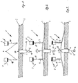
- the glass plate 3 is curved by means of suction lifting devices 25.
- the suction lifting devices 25 are on both sides a desired dividing line or scribe line 26 of a glass sheet 3 arranged. They are preferably parallel to the scoring line 26 on both sides a series of spaced apart Suction lifting devices 25.
- Each suction lifting device 25 comprises a suction cup 27 made with a piston-cylinder unit 28 a rest position on a glass panel 3 lowerable or from it is designed to be liftable.
- the suction cups 27 can in particular activated with pneumatic devices (not shown) or be deactivated.
- the suction cups 27 are immediately or indirectly via the piston-cylinder units 28 with a linkage 29, in particular a spindle 29 in connection with a drive 30.
- the drive 30 can the suction cups 27 and optionally a glass plate 3 sucked onto it for arching over the spindle 29 move up or down.
- the drive is special an electromotive servo drive.
- Suction lifting devices 25 are present, which run along the middle above the score line 26 is arranged. In this embodiment suck the suction lifting devices 25 the glass panel 3 in the center Score line 26 and then lift it up.
- a glass plate 3 on the Processing table 2 positioned that the score line 26 above the breaker bar 4 is arranged.
- the hold-down devices 8 are in a rest position. Then will the breaker bar by means of the spindles 7 and the drives 6 Scoring line 26 moved out of processing table 2, whereby the glass plate 3 is arched. For example carried out a first phase of force application until the curvature reaches the hold-down bars 9. Subsequently is arched up further, the bulging glass plate 3 the hold-down devices 8 lifts up to their end stops (Fig. 3).
- the breaker bar 4 can Evenly raised across the entire width of the glass sheet be (Fig. 5, 6). Should one by scratching the glass plate introduced crack, however, from one side of the glass plate to opposite side of the glass plate with respect to the crack depth decrease or increase or a different voltage distribution in the glass may be necessary for other reasons, the breaker bar 4 can also be lifted more on one side of the glass panel than on the opposite side (Fig. 8).
- the breaker bar can then also on the previously lowered end up to the higher level of the initially raised side of the Crushing bar can be raised (Fig. 9).
- the break can, however also from one side of the glass panel.
- the suction devices are first 15 with the suction cups 16 from below onto the glass panel moved up and the glass panel from the suction cups 16 sucked. Then the breaker bar is described in Way the glass panel 3 bulging out of the processing table 2 pulled out. Here the suction devices also lifted up against the reset devices 20. When the crushing bar 4 is raised further, the suction devices arrive 15 with the reset devices 20 in their end stops, which also increases the already described Bending moment is brought about.
- both with hold-down devices 8 and suction devices 15 can both hold-down devices 8 and the suction devices 15 or both act on the glass sheet.
- the suction cups are first 27 lowered to the top of the glass sheet and suck themselves there by the glass. Then the glass plate is removed using the Drives 30 and raised over the spindles 29 such that they bulges (Fig. 19).
- the suction cups in the area Scoring line 26 lowered onto the glass plate and suck themselves there firmly. Then the glass plate over the rods 29 or Spindles 29 and the drives 30 are arched (Fig. 23, 24) until the plate breaks.
- the Breaking edge is optimized in such a way that it can easily be called Visible edge on furniture glass, glass for motor vehicles or glass can be used in the construction or interior design sector, in particular with little or no reworking. Furthermore Micro cracks that run across the main crack, flaky, ripple or shell mussiness of the crack.
Abstract
Description
Die Erfindung betrifft ein Verfahren zum Brechen von Glasplatten
nach dem Oberbegriff des Anspruch 1 und eine Vorrichtung zum
Durchführen des Verfahrens nach dem Oberbegriff des Anspruch 26.The invention relates to a method for breaking glass plates
according to the preamble of claim 1 and a device for
Carrying out the method according to the preamble of
Zum Aufteilen von Glasplatten bzw. Glasrohtafeln ist es bekannt, diese oberseitig anzuritzen und anschließend unterseitig mit einer Brechleiste anzuheben, so daß im Bereich der Ritzlinie ein Biegemoment auf die Glasplatte aufgebracht wird, welches durch stetiges Anheben irgendwann so groß wird, daß die Scheibe im Bereich der Ritzlinie durchbricht. Um das Biegeverhalten der zu brechenden Glasplatte zu beeinflussen, ist es bekannt, entlang der Ritzlinie, beidseitig der Ritzlinie die Scheibe mit Saugnäpfen anzusaugen oder mit Niederhaltern definiert niederzudrücken. Dabei können die Saugnäpfe oder die Niederhalter die Anhebebewegung durch die Brechleiste über einen bestimmten Weg mitmachen, bis sie in Endanschläge geraten, so daß die Kräfte, die auf die Scheibe wirken, schlagartig erhöht werden.For dividing glass plates or raw glass panels, it is known to scratch them on the top and then on the underside a crowbar to raise so that in the area of the score line Bending moment is applied to the glass plate, which by steady lifting will eventually become so big that the disc in the Area of the scratch line breaks through. To the bending behavior of the to affect breaking glass plate, it is known to along the scoring line, the disc with suction cups on both sides of the scoring line to be sucked in or pressed down with hold-down devices. The suction cups or the hold-down device can be used for the lifting movement join through the crowbar along a certain path, until they reach end stops, so that the forces on the Disc act, suddenly increased.
Bei in herkömmlicher Weise gebrochenem Glas verläuft die Bruchkante unregelmäßig. So ist z.B. die Bruchkante in Längsrichtung nicht gerade, sondern mehr oder weniger wellig. In Querrichtung bzw. in Dickenrichtung verläuft die Bruchkante nicht wie erwünscht senkrecht zur Glasoberfläche sondern schiefwinklig. Zudem entstehen sogenannte Nebenrisse, welche mehr oder weniger parallel zur Hauptbruchkante verlaufen, woraus z.B. insbesondere muscheliger oder schuppiger Bruch resultiert. Außerdem könnten Mikrorisse entstehen, die quer zum Hauptbruch in das Glas hinein laufen; diese führen bei der Weiterverarbeitung einer gebrochenen Glasscheibe zum Bruch. Insbesondere bei wechselnden thermischen Belastungen, wie im Einbau von Glasscheiben in Wintergärten, verursachen derartige Kanten Probleme. Aber auch bei Glas für den Möbelbau, Glas für Kraftfahrzeuge oder Glas im Bau- bzw. Innenausbausektor führt diese Ausbildung der Kanten dazu, daß die Kanten nach dem Brechen abgeschliffen werden müssen. Hierfür müssen die Glastafeln von vornherein mit einem Übermaß hergestellt werden und werden anschließend sehr aufwendig auf Endmaß abgeschliffen.In the case of glass broken in a conventional manner, the breaking edge runs irregular. For example, the breaking edge in the longitudinal direction not straight, but more or less wavy. In the transverse direction or in the thickness direction, the breaking edge does not run as desired perpendicular to the glass surface but at an oblique angle. In addition, so-called side cracks arise, which more or less run parallel to the main breaking edge, from which e.g. in particular mussel or scaly fracture results. Besides, could Microcracks develop that cross into the main break into the glass to run; these result in the further processing of a broken one Glass pane to break. Especially with changing thermal Loads, such as in the installation of glass panes in winter gardens, such edges cause problems. But also with glass for furniture construction, glass for motor vehicles or glass in construction or Interior construction leads to the formation of the edges that the edges have to be sanded after breaking. Therefor the glass panels must be made with an oversize from the outset are and then become very complex to the final dimension abraded.
Aufgabe der Erfindung ist es, ein Verfahren und eine Vorrichtung zum Brechen von Glasplatten zu schaffen, welche eine saubere, fehlerfreie Kante ergeben.The object of the invention is a method and an apparatus for breaking glass plates that provide a clean, result in a flawless edge.
Die Aufgabe wird mit einem Verfahren mit den Merkmalen des Anspruch
1 sowie einer Vorrichtung nach Anspruch 26 gelöst. Vorteilhafte
Weiterbildungen sind in Unteransprüchen gekennzeichnet.The task is accomplished with a method with the features of the claim
1 and a device according to
Das erfindungsgemäße Verfahren sieht vor, den Effekt der sogenannten langsamen Rißausbildung beim Brechen von Glas auszunutzen. Diese langsame Rißausbreitung kann am Grund einer Anritzspur im Glas stattfinden. Erfindungsgemäß wurde herausgefunden, daß eine langsame Rißausbreitung ab einem bestimmten Lastniveau dann kontrolliert stattfinden kann, wenn zumindest nach dem Erreichen dieses Lastniveaus abhängig von der Glasdicke eine bestimmte Steigerung des Lasteintrages eingehalten wird. Die sich dann ergebende, kontrollierte langsame Rißausbreitung führt zu einem Riß bzw. einem Bruch der sehr glatte und ebene Bruchkanten mit einem senkrechten Verlauf zur Glastafelebene aufweist.The method according to the invention provides the effect of the so-called slow crack formation when breaking glass. This slow crack propagation can be at the bottom of a scratch mark take place in the glass. According to the invention, it was found that a slow crack propagation from a certain load level can take place in a controlled manner if at least after the Reach this load level depending on the glass thickness certain increase in the load entry is observed. The resulting, controlled, slow crack propagation to a crack or break of the very smooth and flat breaking edges with a perpendicular course to the glass sheet level.
Die erforderliche Bruchlast wird beispielsweise durch das Wölben der Glasplatte aufgebracht. Um die Last zu messen bzw. zu regeln, kann sowohl die durch die Wölbungsmittel eingeleitete Kraft direkt gemessen oder geregelt werden, oder indirekt über die Höhe bzw. Stärke der Wölbung bestimmt werden.The required breaking load is caused, for example, by the bulging applied to the glass plate. To measure or control the load, can both the one initiated by the bulge Force can be measured or regulated directly, or indirectly via the height or strength of the curvature can be determined.
Erfindungsgemäß wird zur Ermittlung der für die langsame Rißausbreitung notwendigen Lasthöhe zunächst die Bruchlast Fkrit. und/-oder bei eingestellter Wölbung bzw. Verformungsgeschwindigkeit die Zeit bis zum Bruch Tkrit. und/oder die für den Bruch notwendige Stärke der Wölbung bzw. Verformung, das heißt der Weg bis zum Bruch Skrit. bestimmt. Anschließend wird das Lastniveau festgelegt, das mindestens notwendig ist für eine langsame Rißausbreitung. Dieser Schwellenwert Ts, Fs oder Ss liegt bei ca. 70 bis 80% der Bruchlast. Anschließend wird eine Laststeigerungsrate eingestellt, die noch so niedrig ist, daß die langsame Rißausbreitung stattfindet. An den jeweiligen Bruchbildern kann dann sehr einfach ermittelt werden, ob noch eine langsame Rißausbreitung stattgefunden hat, da dann glatte Bruchkanten vorliegen.According to the invention, the breaking load F crit. And / or, if the curvature or deformation rate is set, the time until the break T crit. And / or the strength of the curvature or deformation necessary for the fracture is determined to determine the load height necessary for the slow crack propagation . that means the way to the break S crit . The load level that is at least necessary for slow crack propagation is then determined. This threshold value T s , F s or S s is approximately 70 to 80% of the breaking load. Then a load increase rate is set which is still so low that the slow crack propagation takes place. It is then very easy to determine from the respective fracture patterns whether slow crack propagation has taken place, since smooth fracture edges are then present.
Die Laststeigerungsrate ist dabei von der Glasdicke abhängig. Nach der Erfindung findet das Brechen des Glases somit bei linearer Lasterhöhung über die Zeit so langsam statt, daß die langsame Rißausbreitung gewährleistet ist. Um das Brechen zu beschleunigen, kann erfindungsgemäß bis zum Erreichen der Lastschwelle die Laststeigerung relativ schnell erfolgen, insbesondere in einer im Stand der Technik üblichen Geschwindigkeit und erst nach dem für eine langsame Rißausbreitung notwendigen Schwellenwert bzw. einem entsprechenden Schwellenbereich die Laststeigerungsrate zur Ausbildung einer langsamen Rißausbreitung gesenkt werden. Um die Laststeigerungsrate an die sich durch die Vertiefung des Risses effektiv verringernde Glasdicke anzupassen, kann die Laststeigerungsrate auch kontinuierlich verringert oder erhöht werden.The rate of load increase depends on the glass thickness. According to the invention, the breaking of the glass takes place in a linear manner Load increase over time so slowly that the slow crack propagation is guaranteed. To break up too accelerate, according to the invention, until the load threshold is reached the load increase can be done relatively quickly, in particular at a speed customary in the prior art and only after that necessary for slow crack propagation Threshold or a corresponding threshold range Rate of load increase to form a slow crack propagation be lowered. To the load increase rate itself effectively reducing glass thickness by deepening the crack adapt, the rate of load increase can also be continuous be reduced or increased.
Erfindungsgemäß können ferner alle äußeren Einflüsse, die das Brechen des Glases beeinflussen, ermittelt werden und hieraus Steuerdaten für eine Maschinensteuerung derart erzeugt werden, daß beispielsweise für alle möglichen Glassorten und Glasdicken ein optimaler Schwellenwert der langsamen Rißausbildung und/oder eine optimale Laststeigerungsrate ermittelt und als Steuerdaten abgelegt werden.According to the invention, all external influences that the Break the glass affect, be determined and from there Control data for a machine control are generated in such a way that, for example, for all possible types of glass and glass thickness an optimal threshold of slow cracking and / or an optimal load increase rate is determined and as tax data be filed.
Die erfindungsgemäße Vorrichtung besitzt eine oder mehrere Brechleisten und/oder Sauger o.ä., die insbesondere elektromotorisch weg- oder kraftgesteuert angehoben werden, so daß jeder zeit die in die Glasplatte eingetragene Kraft bekannt und kontrollierbar ist. Um das Biegemoment, welches im Bereich der Ritzlinie eingebracht wird, zu definieren und zu kontrollieren, können Niederhalter und/oder Sauger verwendet werden, welche beidseitig neben der Ritzlinie auf das Glas einwirken.The device according to the invention has one or more Crushing bars and / or suction cups or the like, which are especially electric be lifted away or force controlled so that everyone time the force entered in the glass plate is known and controllable is. To the bending moment, which is in the range of Scoring line is introduced to define and control hold-down devices and / or suction cups can be used, which act on both sides of the glass next to the scratch line.
Bei dem erfindungsgemäßen Verfahren ist von Vorteil, daß durch das Herbeiführen einer langsamen Rißausbreitung bis zum Bruch ein absolut gleichmäßiger Riß- bzw. Bruchverlauf erzielt wird, der eine derart saubere Kante hinterläßt, daß diese Kanten nicht nachbearbeitet werden müssen. Hierbei ist von Vorteil, daß die Glasplatten nicht mit Übermaß hergestellt werden müssen, da die entstehende Bruchkante auch höchsten Ansprüchen bezüglich der Welligkeit, Muscheligkeit etc. genügt und ohne weitere Nachbearbeitung auch im Sichtbereich verarbeitbar ist.In the method according to the invention it is advantageous that causing slow crack propagation to break an absolutely uniform crack or fracture course is achieved, which leaves such a clean edge that these edges do not have to be reworked. The advantage here is that the Glass plates do not have to be manufactured in excess, as the resulting breaking edge also meet the highest demands in terms of Waviness, musseliness etc. is sufficient and without further post-processing can also be processed in the visible area.
Die Erfindung wird beispielhaft anhand einer Zeichnung erläutert.
Es zeigen dabei:
Um eine Glasplatte oder Glastafel 1 zu brechen, wird die Glasplatte oder Glastafel zunächst in herkömmlicher Weise im Bereich der gewünschten Trennlinie mit einem Schneidrädchen oder anderen geeigneten Mitteln angeritzt und hierdurch eine Ritzlinie entlang der gewünschten Trennungslinie erzeugt. Anschließend wird die Glasplatte oder Glastafel in eine Brechvorrichtung verfahren. Um einen Bruch der Glasplatte oder Glastafel herbeizuführen, wird die Glasplatte oder Glastafel im Bereich der Ritzlinie - insbesondere zur Ritzlinie hin - aufgewölbt, oder durch Abklappen eines Tischbereichs oder andere geeignete Mittel oder Methoden der Bruch herbeigeführt.To break a glass plate or glass sheet 1, the glass plate or glass panel first in the conventional manner in the area the desired dividing line with a cutting wheel or other suitable means scratched and thereby along a scratch line the desired dividing line. Then will move the glass plate or glass sheet into a breaking device. In order to break the glass plate or glass sheet, becomes the glass plate or glass sheet in the area of the scratch line - especially towards the scoring line - arched, or by folding down a table area or other suitable means or Methods of breakage brought about.
Um die Bruchlast Fkrit. zu bestimmten, bei der eine bestimmte Glasplatte einer vorgegebenen Dicke entlang der zuvor mit einem bestimmten Schneidrädchen aufgebrachten Ritzlinie bricht, wird die Glasplatte mit einer Last (Kraft) und einer bestimmten Laststeigerungsrate beaufschlagt (Fig. 25a). Die Laststeigerungsrate, das heißt die Zunahme der Last pro Zeit entspricht dabei beispielsweise den im Stand der Technik üblichen Laststeigerungsraten, die sehr hoch sind. Eine langsame Rißausbreitung ist bei diesen hohen Laststeigerungsraten nicht möglich. Erfindungsgemäß wurde erkannt, daß der sich durch eine kontrollierte, kontinuierlich stattfindende langsame Rißausbreitung ergebende Bruch, saubere, gerade und senkrecht zur Glasoberfläche verlaufende Bruchkanten ergibt.In order to determine the breaking load F crit. At which a certain glass plate of a predetermined thickness breaks along the scratch line previously applied with a certain cutting wheel, the glass plate is subjected to a load (force) and a specific load increase rate (FIG. 25a). The load increase rate, that is to say the increase in the load per time, corresponds, for example, to the load increase rates which are customary in the prior art and which are very high. A slow crack propagation is not possible with these high load increase rates. According to the invention, it was recognized that the fracture resulting from a controlled, continuous, slow crack propagation resulted in clean, straight and perpendicular fracture edges.
Erfindungsgemäß wurde ferner herausgefunden, daß für eine kontrollierte und technisch nutzbare langsame Rißausbreitung ein Mindestlastniveau bzw. eine Lastschwelle Fs notwendig ist. Zumindest oberhalb dieser Lastschwelle Fs wird eine Laststeigerungsrate eingestellt, bei der abhängig unter anderem von der Dicke des Glases eine kontrollierte, kontinuierliche, langsame Rißausbreitung stattfindet. Üblicherweise sind mit zunehmender Glasdicke geringere Laststeigerungsraten notwendig (Fig. 25f). Die Lastschwelle Fs liegt erfindungsgemäß üblicherweise bei etwa 70 bis 80% der Bruchlast. Sie ist - wie die geeignete Laststeigerungsrate - vorzugsweise für jede Glassorte und -dicke empirisch zu bestimmen und kann von dem angegebenen Wert auch abweichen. Im einfachsten Fall (Fig. 25b) kann eine einheitliche Laststeigerungsrate gewählt werden, die der für die langsame Rißausbreitung geeigneten Laststeigerungsrate oberhalb der Lastschwelle Fs entspricht. Um den Brechvorgang in vorteilhafter Weise zu beschleunigen, kann die Laststeigerungsrate bis zum Erreichen der Lastschwelle Fs jedoch auch sehr hoch gewählt werden und erst nach dem Erreichen der Schwellenlast den Verlauf der für die langsame Rißausbildung günstigen Laststeigerungsrate annehmen (Fig. 25c). Erfindungsgemäß wurde gefunden, daß der Bereich vor dem Erreichen der Schwellenlast Fs bezüglich der Laststeigerungsrate im wesentlichen unkritisch ist, so daß auch durch eine sehr hohe Laststeigerungsrate in diesem Bereich Zeit gespart werden kann. Die Übergänge der unterschiedlichen Laststeigerungsraten müssen hierbei nicht abrupt sein, vielmehr können sie fließend übergehen (Fig. 25d, 25e).According to the invention it was also found that a minimum load level or a load threshold F s is necessary for a controlled and technically usable slow crack propagation. A load increase rate is set at least above this load threshold F s , at which a controlled, continuous, slow crack propagation takes place depending on, among other things, the thickness of the glass. As the glass thickness increases, lower load increase rates are usually necessary (Fig. 25f). According to the invention, the load threshold F s is usually around 70 to 80% of the breaking load. Like the appropriate rate of increase in load, it should preferably be determined empirically for each type and thickness of glass and may also deviate from the stated value. In the simplest case (FIG. 25b), a uniform load increase rate can be selected which corresponds to the load increase rate above the load threshold F s suitable for slow crack propagation. In order to accelerate the breaking process in an advantageous manner, the load increase rate can be chosen to be very high until the load threshold F s is reached and only after the threshold load has been reached can the course of the load increase rate favorable for the slow crack formation be assumed (FIG. 25c). According to the invention, it was found that the area before the threshold load F s is reached is essentially uncritical with regard to the rate of increase in load, so that time can also be saved in this area by a very high rate of increase in load. The transitions of the different load increase rates do not have to be abrupt here, rather they can transition smoothly (FIGS. 25d, 25e).
Insbesondere kann die Laststeigerungsrate oberhalb der Lastschwelle Fs derart verlaufen, daß sie an den Rißfortschritt angepaßt ist. Durch den Rißfortschritt unterhalb der Ritzlinie wird die effektive Glasdicke, das heißt die Glasdicke zwischen dem Rißgrund und der der Ritzlinie gegenüberliegenden Glasoberfläche immer geringer. Da ein Zusammenhang zwischen der für die Ausbildung der langsamen Rißausbreitung günstigen Laststeigerungsrate und der Glasdicke besteht, kann die Laststeigerungsrate an die effektive Glasdicke angepaßt werden. Die Laststeigerungsrate kann dabei über die Zeit verringert werden (Fig. 25d) oder erhöht werden (Fig. 25g), was insbesondere empirisch ermittelt wird. Auch hierbei können die Laststeigerungsraten fließend ineinander übergehen (Fig. 25h).In particular, the load increase rate above the load threshold F s can be such that it is adapted to the crack propagation. As the crack progresses below the scratch line, the effective glass thickness, that is to say the glass thickness between the crack base and the glass surface opposite the scratch line, becomes ever smaller. Since there is a connection between the load increase rate which is favorable for the formation of the slow crack propagation and the glass thickness, the load increase rate can be adapted to the effective glass thickness. The rate of load increase can be reduced over time (Fig. 25d) or increased (Fig. 25g), which is determined empirically in particular. Here, too, the load increase rates can flow smoothly into one another (Fig. 25h).
Erfindungsgemäß wird vorteilhafterweise eine Schneidflüssigkeit auf Wasserbasis verwendet, also insbesondere wäßrige Emulsionen oder Suspensionen. Mit derartigen Schneidflüssigkeiten ist die langsame Rißausbreitung besonders gut ausgebildet und gut kontrollierbar, wobei der Bereich zwischen erforderlicher Lastschwelle Fs und der Bruchlast einerseits und der Bereich der günstigen Laststeigerungsraten andererseits relativ groß ist.According to the invention, a water-based cutting fluid is advantageously used, in particular aqueous emulsions or suspensions. With such cutting fluids, the slow crack propagation is particularly well designed and easy to control, the range between the required load threshold F s and the breaking load on the one hand and the range of favorable load increase rates on the other hand being relatively large.
Einen Einfluß auf die Art der Rißausbreitung und damit auf die günstigen Laststeigerungsraten haben insbesondere:
- Glasdicke
- Glasart
- Schneidrädchenart
- Schneidrädchenwinkel
- Schneidrädchendurchmesser
- Schneidrädchenschliff (glatt oder rauh) - Schneidrädchenabnutzung
- Schneidflüssigkeit
- Schneiddruck
- Schneidgeschwindigkeit
- Massenverteilung links und rechts vom Schnitt.
- Art und Weise des Lasteintragens (Wölben, Abkanten, etc.)
- glass thickness
- Type of glass
- Schneidrädchenart
- cutting wheel angle
- cutting wheel diameter
- Cutting wheel cut (smooth or rough) - Cutting wheel wear
- cutting oil
- cutting pressure
- cutting speed
- Mass distribution left and right of the cut.
- Type of load entry (arching, folding, etc.)
Diese Parameter werden vorzugsweise bei der empirischen Ermittlung der Lastschwelle und/oder der Laststeigerungsrate berücksichtigt.These parameters are preferably used in the empirical determination the load threshold and / or the load increase rate are taken into account.
Die empirisch für die oben genannten und gegebenenfalls weitere Parameter ermittelten Einflußgrößen auf die Zielgrößen-Lastschwelle Fs und Laststeigerungsrate lassen sich insbesondere als Daten für eine Maschinensteuerung ablegen. Die Parameter können für den Betrieb einer nach dem erfindungsgemäßen Verfahren arbeitenden Vorrichtung manuell oder automatisiert erfaßt werden und die Vorrichtung entsprechend gesteuert werden. Gegebenenfalls kann nach der Begutachtung eines Bruchbildes eine Nachregelung erfolgen. Ein typisches Bruchbild zeigt einen Bereich, der durch das Anritzen entstanden ist, einen sauberen glatten Bereich und - sofern eine erfindungsgemäße langsame Rißausbreitung nicht stattgefunden hat - gegebenenfalls noch einen Bereich, der einen energiereichen, unsauberen Bruch zeigt.The influencing variables on the target variable load threshold F s and load increase rate determined empirically for the above-mentioned and possibly further parameters can be stored in particular as data for a machine control. The parameters for the operation of a device operating according to the method according to the invention can be recorded manually or automatically and the device can be controlled accordingly. If necessary, a readjustment can be made after the assessment of a fracture pattern. A typical fracture pattern shows an area that has been created by scoring, a clean, smooth area and - if slow crack propagation according to the invention has not taken place - possibly also an area that shows a high-energy, unclean fracture.
Um eine günstige Lastschwelle Fs zu ermitteln, wird, wie bereits ausgeführt, die Bruchlast Fkrit. ermittelt. Anschließend wird die Last bis zur Lastschwelle mit einer relativ hohen - insbesondere im Stand der Technik üblichen - Laststeigerungsrate erhöht. Die Lastschwelle Fs wird dabei zunächst in dem Bereich zwischen 70 und 80% der Bruchlast Fkrit. gelegt, da sich bei einer solchen Lasthöhe üblicherweise gute Ergebnisse zeigen. In einem nachfolgenden Versuch wird nach dem Erreichen dieser festgelegten Lastschwelle Fs die Last mit einer Laststeigerungsrate erhöht, die - erfahrungsgemäß - relativ niedrig, jedoch deutlich niedriger als die Laststeigerungsrate bis zum Erreichen der Lastschwelle ist.In order to determine a favorable load threshold F s , the breaking load F crit. Is determined, as already stated. Subsequently, the load is increased up to the load threshold with a relatively high load increase rate, particularly in the state of the art. The load threshold F s is first crit in the range between 70 and 80% of the breaking load F. Specified, since usually show good results in such a load height. In a subsequent experiment, once this defined load threshold F s has been reached, the load is increased at a rate of increase in load which, based on experience, is relatively low, but is significantly lower than the rate of increase in load until the load threshold is reached.
Die Laststeigerungsrate wird hierbei insbesondere über die Zeit festgelegt, die zwischen dem Erreichen der Lastschwelle Fs und dem Bruch (Erreichen der Bruchlast Fkrit.) liegt (Fig. 25f).The rate of increase in load is determined in particular over the time which lies between reaching the load threshold F s and breaking (reaching breaking load F crit. ) (FIG. 25f).
Für die Festlegung einer Ausgangslaststeigerungsrate wird die
Zeit nach der Formel
Nach dem in der festgelegten Zeit herbeigeführten Bruch werden die Bruchkanten analysiert. Zeigen die Bruchkanten die gewünschte optimierte Bruchkante, ist eine Korrektur nicht nötig. Sind - insbesondere im letzten Abschnitt des Bruchs - Anzeichen eines energiereichen muscheligen Bruchs zu erkennen, kann die Lastschwelle verändert werden, insbesondere abgesenkt werden und/-oder die Zeit Td verlängert werden, was einer Absenkung der Laststeigerungsrate entspricht.After the break caused in the specified time, the break edges are analyzed. If the breaklines show the desired optimized breakline, a correction is not necessary. If, particularly in the last section of the break, there are signs of an energy-rich mussel break, the load threshold can be changed, in particular lowered and / or the time T d can be extended, which corresponds to a decrease in the rate of increase in load.
Zeigt der Bruch einen optimalen Verlauf, kann zur Beschleunigung des gesamten Brechvorganges die Laststeigerungsrate und/oder die Lastschwelle erhöht werden, bis der Bruch wieder muschelige, nicht optimierte Bereiche zeigt. Hierdurch kann der Bereich eingegrenzt bzw. abgegrenzt werden, indem eine langsame Rißausbreitung sicher erzielbar ist. If the break shows an optimal course, it can accelerate of the entire crushing process, the load increase rate and / or the Load threshold can be increased until the break is again mussel, shows non-optimized areas. This allows the area to be limited or delimited by slow crack propagation is safely achievable.
Es hat sich herausgestellt, daß es vorteilhaft sein kann, die Laststeigerung während des Lasteintrages und oberhalb der Lastschwelle für eine kurze Zeit auszusetzen, das heißt die von außen aufgebrachte Last für eine bestimmte Zeit konstant zu halten. Eine derartige Haltephase (Fig. 25i bis 25p) ist vorteilhaft, wenn eine Homogenisierung der im Glas aufgrund des Lasteintrages herrschenden Spannung vorgenommen werden soll. Die Laststeigerung bis zum Bruch erfolgt hierbei somit in drei Phasen; einer Laststeigerungsphase 1 zumindest bis zum Erreichen der Lastschwelle Fs oder darüber, einer Lasthaltephase II und anschließend einer Laststeigerungsphase III bis zum Bruch (Fig. 25i bis 25p, lediglich grob schematisch und nicht quantitative Darstellung).It has been found that it can be advantageous to suspend the load increase during the load entry and above the load threshold for a short time, that is to say to keep the externally applied load constant for a certain time. Such a holding phase (FIGS. 25i to 25p) is advantageous if the voltage prevailing in the glass due to the load input is to be homogenized. The load increase up to the break occurs in three phases; a load increase phase 1 at least until the load threshold F s or above is reached, a load holding phase II and then a load increase phase III until breakage (FIGS. 25i to 25p, only roughly schematic and not quantitative representation).
Im Bereich I kann bis zum Erreichen der Lastschwelle die Laststeigerungsrate hoch bis sehr hoch sein. Die hierdurch eingetragenen Spannungen können während der Lasthaltephase unter Initiierung und Fortführung der langsamen Rißausbreitung bei Homogenisierung der Spannung insbesondere über die Rißlänge abgebaut werden. In der Laststeigerungsphase III wird eine Laststeigerungsrate gewählt, die die weitere langsame Rißausbreitung gewährleistet. In den drei Phasen I, II, III können die Laststeigerungsraten linear (Fig. 25i) oder nicht linear (Fig. 25j bis 25p) verlaufen, wobei abrupte (Fig. 25i) und fließende Übergänge (Fig. 25j bis 251) möglich sind.In area I the load increase rate can be reached until the load threshold is reached be high to very high. The hereby entered Tensions can be initiated during the load holding phase and continued slow crack propagation upon homogenization the stress is relieved especially over the crack length become. In the load increase phase III there is a load increase rate chosen, which ensures the further slow crack propagation. In the three phases I, II, III, the load increase rates linear (Fig. 25i) or non-linear (Fig. 25j to 25p), with abrupt (Fig. 25i) and flowing transitions (Fig. 25j to 251) are possible.
In besonderen Fällen, beispielsweise bei besonders hartem oder dicken Glas kann zur Rißinitialisierung zunächst auch ein hoher Lasteintrag vorgenommen werden, der über der Lastschwelle Fs liegt und während der Phase II eine nachfolgende Entlastung (Entspannungsphase II) vorgesehen sein.In special cases, for example in the case of particularly hard or thick glass, a high load input which is above the load threshold F s can also be undertaken initially for crack initialization and a subsequent relief (relaxation phase II) can be provided during phase II.
Die erfindungsgemäße Vorrichtung 1 (Fig. 1 bis 24) besitzt einen Bearbeitungstisch 2 zum Auflegen von Glasplatten oder Glastafeln 3. The device 1 according to the invention (FIGS. 1 to 24) has one Processing table 2 for placing glass plates or glass panels Third
Zum Wölben der Glastafel 3 ist beispielsweise eine sogenannte
Brechleiste 4 vorhanden. Die Brechleiste 4 ist ein langgestreckter
Körper in Form eines Balkens oder einer Leiste. Die Brechleiste
4 ist in einer schlitzförmigen Aussparung 5 im Bearbeitungstisch
2 angeordnet. Die Aussparung 5 erstreckt sich quer
zur Längserstreckung des Bearbeitungstisches 2 und ist vorzugsweise
kürzer als die Tischbreite aber länger als die Breite
einer aufgelegten Glasplatte 3. Die Brechleiste 4 bestitzt einen
oder mehrere Antriebe 6, die über ein Gestänge 7, insbesondere
eine Spindel 7 jeweils auf die Brechleiste 4 derart einwirken,
daß die Brechleiste 4 nach oben aus dem Schlitz herausfahrbar
und in diesen wieder hereinfahrbar ist.For arching the
Oberhalb des Bearbeitungstisches 2 sind beidseitig des Schlitzes
5 bzw. der Brechleiste 4 Niederhaltereinrichtungen 8 vorhanden.
Die Niederhaltereinrichtungen 8 besitzen je eine Niederhalteleiste
9. Die Niederhalterleisten 9 sind langgestreckt ausgebildet
und verlaufen parallel zur Aussparung 5, wobei sie eine Länge
aufweisen, die in etwa der Länge der Brechleiste 4 entspricht.
Die Niederhalterleisten 9 sind über ein Gestänge 10 o.ä. mit
Rückstelleinrichtungen 11 derart verbunden, daß die Niederhalteleisten
9 aus einer unteren Ruhelage gegen die Kraft der Rückstelleinrichtungen
11 bis zum Erreichen von Endanschlägen anhebbar
sind. Die Rückstelleinrichtungen 11 sind beispielsweise
Federpakete oder Gasdruckfedern. Die Niederhaltereinrichtungen
9 lassen sich unter Verringerung ihres Abstandes aufeinander zu
fahren und umgekehrt, wobei jede Niederhalterleiste 9 näher an
die Brechleiste gefahren wird und umgekehrt.Above the processing table 2 are the slot on both
Bei einer weiteren vorteilhaften Ausführungsform (Fig. 10 bis
13) sind benachbart zur Aussparung 5 und entlang der Aussparung
5 Saugereinrichtungen 15 vorhanden. Die Saugereinrichtung 15
umfaßt insbesondere runde Saugnäpfe 16, welche unterhalb einer
auf den Tisch 2 aufzulegenden Glastafel 3 in insbesondere runden
Aussparungen 17 angeordnet sind. Die Saugnäpfe 16 sind mittels
Kolbenzylindereinheiten 18 an eine Glasplatte 13 heranfahrbar
und von dieser weg fahrbar, wobei die Saugnäpfe 16 mit entsprechenden,
insbesondere pneumatischen Einrichtungen (nicht gezeigt)
sich an einer Glasplatte ansaugen können und das Ansaugen
wieder lösen können.In a further advantageous embodiment (Fig. 10 to
13) are adjacent to the
Die Saugnäpfe 16 sind unmittelbar oder mittelbar über die Kolbenzylindereinheiten
18 über ein Gestänge 19 mit einer Rückstelleinrichtung
20 derart verbunden, daß sie gegen die Kraft
der Rückstelleinrichtungen 20 aus dem Tisch 2 heraushebbar sind
bis zu einem Endanschlag der Rückstelleinrichtungen 20. Die
Rückstelleinrichtungen 20 können z.B. Federpakete oder Gasdruckfedern
sein.The suction cups 16 are directly or indirectly via the piston-
Ferner ist es auch möglich, sowohl Niederhaltereinrichtungen 8
als auch Saugeinrichtungen gleichzeitig vorzusehen (Fig. 14 bis
16), um sie alternativ oder gemeinsam zu verwenden.Furthermore, it is also possible to hold down
Bei einer weiteren vorteilhaften Ausführungsform (Fig. 17 bis
20) erfolgt die Wölbung der Glasplatte 3 mittels Saughebeeinrichtungen
25. Die Saughebeeinrichtungen 25 sind beiderseits
einer gewünschten Trennlinie bzw. Ritzlinie 26 einer Glastafel
3 angeordnet. Vorzugsweise befinden sich je parallel zur Ritzlinie
26 beiderseits je eine Reihe von voneinander beabstandeten
Saughebeeinrichtungen 25. Jede Saughebeeinrichtung 25 umfaßt
einen Saugnapf 27, der mit einer Kolbenzylindereinheit 28 aus
einer Ruheposition auf eine Glastafel 3 absenkbar bzw. von ihr
abhebbar ausgebildet ist. Die Saugnäpfe 27 können insbesondere
mit pneumatischen Einrichtungen (nicht gezeigt) aktiviert oder
deaktiviert werden. Die Saugnäpfe 27 stehen unmittelbar oder
mittelbar über die Kolbenzylindereinheiten 28 mit einem Gestänge
29, insbesondere einer Spindel 29 mit einem Antrieb 30 in Verbindung.
Der Antrieb 30 kann die Saugnäpfe 27 und gegebenenfalls
eine daran angesaugte Glasplatte 3 zum Wölben über die Spindel
29 nach oben bewegen bzw. absenken. Der Antrieb ist insbesondere
ein elektromotorischer Servo-Antrieb.In a further advantageous embodiment (Fig. 17 to
20) the
Bei einer weiteren Ausführungsform ist lediglich eine Reihe von
Saughebeeinrichtungen 25 vorhanden, welche mittig oberhalb entlang
der Ritzlinie 26 angeordnet ist. Bei dieser Ausführungsform
saugen die Saughebeeinrichtungen 25 die Glastafel 3 mittig zur
Ritzlinie 26 an und heben diese anschließend hoch.In another embodiment, only a number of
Im folgenden werden die Funktionsweisen der erfindungsgemäßen Vorrichtungen erläutert.The following are the modes of operation of the invention Devices explained.
Bei erfindungsgemäßen Vorrichtungen mit einer Brechleiste und
Niederhaltern (Fig. 1 bis 6) wird eine Glasplatte 3 so auf dem
Bearbeitungstisch 2 positioniert, daß die Ritzlinie 26 oberhalb
der Brechleiste 4 angeordnet ist. Die Niederhaltereinrichtungen
8 befinden sich hierbei in einer Ruheposition. Anschließend wird
die Brechleiste mittels der Spindeln 7 und der Antriebe 6 zur
Ritzlinie 26 hin aus dem Bearbeitungstisch 2 herausgefahren,
wodurch die Glasplatte 3 aufgewölbt wird. Beispielsweise wird
eine erste Phase der Krafteinleitung so weit durchgeführt, bis
die Wölbung die Niederhalterleisten 9 erreicht. Anschließend
wird weiter aufgewölbt, wobei die sich aufwölbende Glasplatte 3
die Niederhaltereinrichtungen 8 bis in ihre Endanschläge anhebt
(Fig. 3). In dem Moment, in dem die Niederhaltereinrichtungen 8
in ihren Endanschlägen sind, ist eine weitere Aufwölbung der
Glasplatte nur noch zwischen den beidseitig der Ritzlinie 26
angeordneten Niederhaltereinrichtungen 8 möglich, da diese jede
weitere Wölbung unterbinden. Hierdurch kommt es zu einer mehr
oder weniger schlagartigen Momenterhöhung, welche zum endgültigen
Bruch der Glasplatte führt. Die Brechleiste 4 kann hierbei
über die gesamte Breite der Glastafel gleichmäßig angehoben
werden (Fig. 5, 6). Sollte ein durch das Ritzen in die Glasplatte
eingebrachter Riß jedoch von einer Seite der Glasplatte zur
gegenüberliegenden Seite der Glasplatte bezüglich der Rißtiefe
ab- bzw. zunehmen oder eine unterschiedliche Spannungsverteilung
im Glas aus anderen Gründen notwendig sein, kann die Brechleiste
4 an einer Seite der Glastafel auch mehr angehoben werden als an
der gegenüberliegenden Seite (Fig. 8). Hierdurch kann eine Spannungs-
bzw. Biegemomenthomogenisierung über die Breite der Glastafel
erfolgen. Zur Erzielung des endgültigen Bruchs der Glastafel
kann die Brechleiste dann an dem zuvor abgesenkten Ende auch
bis auf das höhere Niveau der zunächst angehobenen Seite der
Brechleiste angehoben werden (Fig. 9). Der Bruch kann jedoch
auch von einer Seite der Glastafel her erfolgen.In devices according to the invention with a crowbar and
Hold down (Fig. 1 to 6) is a
Bei einer Ausführungsform, bei der an Stelle der Niederhalter
Saugereinrichtungen 15 vorhanden sind, werden zunächst die Saugereinrichtungen
15 mit den Saugnäpfen 16 von unten an die Glastafel
herangefahren und die Glastafel von den Saugnäpfen 16
angesaugt. Anschließend wird die Brechleiste in bereits beschriebener
Weise die Glastafel 3 aufwölbend aus dem Bearbeitungstisch
2 herausgefahren. Hierbei werden die Saugeinrichtungen
gegen die Rückstelleinrichtungen 20 ebenfalls empor gehoben.
Bei weiterem Anheben der Brechleiste 4 gelangen die Saugeinrichtungen
15 mit den Rückstelleinrichtungen 20 in ihre Endanschläge,
wodurch ebenfalls die bereits beschriebene Erhöhung des
Biegemoments herbeigeführt wird.In one embodiment, in the place of the hold-
Bei einer Ausführungsform sowohl mit Niederhaltereinrichtungen
8 als auch Saugeinrichtungen 15 können sowohl die Niederhaltereinrichtungen
8 als auch die Saugeinrichtungen 15 oder beide auf
die Glastafel einwirken.In one embodiment, both with hold-down
Bei einer Ausführungsform, bei der die Glasplatte 3 mit Saughebeeinrichtungen
25 angehoben wird, werden zunächst die Saugnäpfe
27 auf die Oberseite der Glastafel abgesenkt und saugen sich
dort am Glas fest. Anschließend wird die Glasplatte mittels der
Antriebe 30 und über die Spindeln 29 derart angehoben, daß sie
sich wölbt (Fig. 19).In one embodiment, in which the
Bei einer Ausführungsform mit Saugeinrichtungen über der Ritzlinie
26 (Fig. 21 bis 24) werden die Saugnäpfe im Bereich der
Ritzlinie 26 auf die Glasplatte abgesenkt und saugen sich dort
fest. Anschließend wird die Glasplatte über die Gestänge 29 bzw.
Spindeln 29 und die Antriebe 30 sich wölbend angehoben (Fig. 23,
24), bis der Bruch der Platte eintritt. In one embodiment with suction devices above the scratch line
26 (Fig. 21 to 24), the suction cups in the
Bei dem erfindungsgemäßen Verfahren ist von Vorteil, daß die Brechkante derart optimiert ist, daß sie ohne weiteres als Sichtkante bei Möbelglas, Glas für Kraftfahrzeuge oder bei Glas im Bau- oder Innenausbausektor verwendet werden kann, insbesondere ohne oder nur mit geringen Nacharbeitungen. Ferner werden Mikrorisse, die quer zum Hauptriß verlaufen, Schuppigkeit, Welligkeit oder Muscheligkeit des Risses vermieden.In the method according to the invention it is advantageous that the Breaking edge is optimized in such a way that it can easily be called Visible edge on furniture glass, glass for motor vehicles or glass can be used in the construction or interior design sector, in particular with little or no reworking. Furthermore Micro cracks that run across the main crack, flaky, ripple or shell mussiness of the crack.
Claims (34)
dadurch gekennzeichnet, daß die Last derart eingetragen wird, daß im Bereich der Ritzlinie eine langsame Rißausbreitung stattfindet, die zum Bruch führt.Process for separating glass, wherein the glass surface is scratched in the area of a desired separation line to initiate a crack and a load is subsequently introduced into the glass in such a way that the break occurs in the area of the scratch line
characterized in that the load is entered in such a way that a slow crack propagation takes place in the area of the score line, which leads to breakage.
dadurch gekennzeichnet, daß die Last mit einer Laststeigerungsrate eingetragen wird, die derart gewählt ist, daß die langsame Rißausbreitung stattfindet.Method according to claim 1,
characterized in that the load is entered at a load increase rate which is selected such that the slow crack propagation takes place.
dadurch gekennzeichnet, daß die Last oberhalb einer bestimmten Lastschwelle (Fs) bis zum Bruch mit einer Laststeigerungsrate eingetragen wird, die so gering ist, daß eine langsame Rißausbreitung stattfindet.Method according to claim 1 and / or 2,
characterized in that the load is entered above a certain load threshold (F s ) until it breaks at a rate of increase in load which is so low that slow crack propagation takes place.
dadurch gekennzeichnet, daß die Lastschwelle (Fs) 65 bis 85, insbesondere 70 bis 80% der Bruchlast (Fkrit) beträgt. Method according to one of the preceding claims,
characterized in that the load threshold (F s ) is 65 to 85, in particular 70 to 80% of the breaking load (F crit ).
dadurch gekennzeichnet, daß die Last bis zur Lastschwelle (Fs) mit einer Laststeigerungsrate eingetragen wird, die höher ist, als die Laststeigerungsrate oberhalb der Lastschwelle, die eine langsame Rißausbreitung gewährleistet.Method according to one of the preceding claims,
characterized in that the load up to the load threshold (F s ) is entered with a load increase rate that is higher than the load increase rate above the load threshold, which ensures slow crack propagation.
dadurch gekennzeichnet, daß die Laststeigerungsrate so gewählt ist, daß sie der allgemeinen Formel
characterized in that the rate of increase in load is chosen so that it corresponds to the general formula
dadurch gekennzeichnet, daß die Referenzglasdicke zwischen 1 und 4 mm beträgt.Method according to claim 6,
characterized in that the reference glass thickness is between 1 and 4 mm.
dadurch gekennzeichnet, daß in dem Erschwernisfaktor α den Glasbruch bestimmende äußere Einflüsse eingerechnet werden.Method according to claim 6 and / or 7,
characterized in that external factors determining glass breakage are included in the difficulty factor α.
dadurch gekennzeichnet, daß in dem Erschwernisfaktor α Größen enthalten sind, die sich aus dem Einfluß der Parameter
- Schneidrädchenwinkel
- Schneidrädchendurchmesser
- Schneidrädchenschliff (glatt oder rauh)
characterized in that the difficulty factor α contains quantities resulting from the influence of the parameters
- cutting wheel angle
- cutting wheel diameter
- Cutting wheel cut (smooth or rough)
dadurch gekennzeichnet, daß, um den Brechvorgang zu beschleunigen, die Laststeigerungsrate bis zum Erreichen der Lastschwelle (Fs) hoch ist und erst nach dem Erreichen der Schwellenlast derart gewählt wird, daß sie einen für die langsame Rißausbildung günstigen Verlauf annimmt.Method according to one of the preceding claims,
characterized in that , in order to accelerate the breaking process, the rate of load increase until the load threshold (F s ) is reached and is only selected after the threshold load has been reached such that it assumes a favorable course for the slow crack formation.
dadurch gekennzeichnet, daß der Übergang der Laststeigerungsrate bis zur Lastschwelle (Fs) zur Laststeigerungsrate oberhalb der Lastschwelle (Fs) abrupt oder fließend ist.Method according to one of the preceding claims,
characterized in that the transition from the rate of increase in load up to the load threshold (F s ) to the rate of increase in load above the load threshold (F s ) is abrupt or smooth.
dadurch gekennzeichnet, daß die Laststeigerungsrate oberhalb der Lastschwelle (Fs) derart gewählt wird, daß sie an den Rißfortschritt und damit die sich verringernde effektive Glasdicke angepaßt ist.Method according to one of the preceding claims,
characterized in that the load increase rate above the load threshold (F s ) is chosen such that it is adapted to the crack propagation and thus the decreasing effective glass thickness.
dadurch gekennzeichnet, daß die Laststeigerungsrate über die Zeit verringert oder erhöht wird, so daß die Laststeigerungsrate einen insbesondere parabolischen oder hyperbolischen Verlauf annimmt. Method according to one of claims 1 to 11 and / or according to claim 12,
characterized in that the rate of increase in load is reduced or increased over time, so that the rate of increase in load assumes a parabolic or hyperbolic course in particular.
dadurch gekennzeichnet, daß als Schneidflüssigkeit beim Anritzen des Glases eine Schneidflüssigkeit auf Wasserbasis verwendet wird.Method according to one of the preceding claims,
characterized in that a water-based cutting fluid is used as the cutting fluid when scribing the glass.
dadurch gekennzeichnet, daß eine wäßrige Emulsion oder eine wäßrige Suspension verwendet wird.The method of claim 14
characterized in that an aqueous emulsion or an aqueous suspension is used.
dadurch gekennzeichnet, daß die Parameter manuell oder automatisiert erfaßt werden und die Einflußgrößen der Parameter als Daten für eine Maschinensteuerung abgelegt werden.Method according to one of claims 7 to 9,
characterized in that the parameters are recorded manually or automatically and the influencing variables of the parameters are stored as data for a machine control.
dadurch gekennzeichnet, daß die Laststeigerung während des Lasteintrages und oberhalb der Lastschwelle für eine kurze Zeit ausgesetzt wird, wobei die von außen aufgebrachte Last konstant gehalten wird.Method according to one of the preceding claims,
characterized in that the increase in load during the load entry and above the load threshold is suspended for a short time, the load applied from the outside being kept constant.
dadurch gekennzeichnet, daß die Last während des Lasteintrages oberhalb der Lastschwelle (Fs) für eine kurze Zeit abgesenkt wird.Method according to one of the preceding claims,
characterized in that the load is lowered for a short time above the load threshold (F s ) during the load entry.
dadurch gekennzeichnet, daß nach dem Konstanthalten und/oder Absenken der Last die Laststeigerung bis zum Bruch mit einer Laststeigerungsrate stattfindet, die eine weitere langsame Rißausbreitung gewährleistet. Method according to claim 17 or 18,
characterized in that after the load has been kept constant and / or lowered, the load increases until it breaks at a load increase rate which ensures a further slow crack propagation.
dadurch gekennzeichnet, daß die Lastschwelle zunächst auf 65 bis 85, insbesondere 70 bis 80 % der Bruchlast festgelegt wird.A method according to claim 20,
characterized in that the load threshold is initially set at 65 to 85, in particular 70 to 80% of the breaking load.
dadurchgekennzeichnet,
daß die Laststeigerungsrate so gewählt wird, daß sie der allgemeine Formel
characterized by
that the rate of increase in load is chosen to conform to the general formula
dadurch gekennzeichnet, daß insbesondere einer oder mehrere der Parameter
- Schneidrädchenwinkel
- Schneidrädchendurchmesser
- Schneidrädchenschliff (glatt oder rauh)
characterized in that in particular one or more of the parameters
- cutting wheel angle
- cutting wheel diameter
- Cutting wheel cut (smooth or rough)
dadurch gekennzeichnet, daß die Einflußgrößen der Parameter in den Faktor α eingerechnet werden.The method of claim 23
characterized in that the influencing variables of the parameters are included in the factor α.
dadurchgekennzeichnet,
daß zur Beschleunigung des Brechvorganges die Laststeigerungsrate und/oder die Lastschwelle so lange erhöht werden, bis der Bruch energiereiche Bereiche zeigt, um den Bereich einzugrenzen bzw. abzugrenzen, in dem eine langsame Rißausbreitung sicher erzielbar ist.Method according to one of claims 20 to 24,
characterized by
that in order to accelerate the breaking process, the load increase rate and / or the load threshold are increased until the fracture shows high-energy areas in order to limit or delimit the area in which slow crack propagation can be achieved with certainty.
dadurch gekennzeichnet, daß die Mittel kraft- oder/oder weggesteuerte Mittel zum Aufbringen der Last mit vorbestimmten Laststeigerungsraten sind. Device for separating glass, the glass surface being scratched in the area of a desired separating line for crack initialization and then a load being introduced into the glass in the area of the separating line by means such that a break occurs in the area of the scored line, in particular device for carrying out the methods according to one of the preceding claims,
characterized in that the means are force or / or path-controlled means for applying the load with predetermined load increase rates.
dadurch gekennzeichnet, daß die Mittel (4, 25) einen elektromotorischen Servoantrieb aufweisen.Device according to claim 26,
characterized in that the means (4, 25) have an electromotive servo drive.
dadurch gekennzeichnet, daß die Mittel (4, 25) eine unter der Ritzlinie angeordnete Brechleiste (4), beidseitig neben der Ritzlinie angeordnete Sauger (25) oder eine im Bereich der Ritzlinie angreifende Saughebeeinrichtung (25) oder eine Brechrolle, die im Bereich der Ritzlinie verfahrbar ist, sind.Device according to claim 26 or 27,
characterized in that the means (4, 25) have a crushing bar (4) arranged under the scoring line, suction cups (25) arranged on both sides next to the scoring line or a suction lifting device (25) engaging in the area of the scoring line or a crushing roller operating in the area of the scoring line is movable, are.
dadurch gekennzeichnet, daß Mittel (8, 15) zur Begrenzung der Aufwölbung einer Glasplatte vorhanden sind.Device according to one of claims 26 to 28,
characterized in that means (8, 15) are provided for limiting the bulging of a glass plate.
dadurch gekennzeichnet, daß die Mittel zur Begrenzung der Aufwölbung beidseitig der Trennlinie angeordnete Niederhalteeinrichtungen (8) oder Saugereinrichtungen (15) sind.Device according to claim 29,
characterized in that the means for limiting the bulge are hold-down devices (8) or suction devices (15) arranged on both sides of the dividing line.
dadurch gekennzeichnet, daß Mittel zur Erfassung eines oder mehrerer der Parameter
- Schneidrädchenwinkel
- Schneidrädchendurchmesser
- Schneidrädchenschliff (glatt oder rauh)
characterized in that means for detecting one or more of the parameters
- cutting wheel angle
- cutting wheel diameter
- Cutting wheel cut (smooth or rough)
dadurch gekennzeichnet, daß Mittel zur Erfassung der eingeleiteten Last vorhanden sind.Device according to one of claims 26 to 31,
characterized in that there are means for detecting the load introduced.
dadurch gekennzeichnet, daß Mittel zur Erfassung des Rißfortschritts und/oder Bruchbeginns vorhanden sind.Device according to one of claims 26 to 32,
characterized in that means are available for detecting crack propagation and / or the beginning of breakage.
dadurch gekennzeichnet, daß eine Steuerung für die Mittel zur Eintragung der Last vorhanden ist, welche die Einflußgrößen eines oder mehrerer der Parameter
- Schneidrädchenwinkel
- Schneidrädchendurchmesser
- Schneidrädchenschliff (glatt oder rauh)
characterized in that there is a control for the means for entering the load, which influences the parameters of one or more of the parameters
- cutting wheel angle
- cutting wheel diameter
- Cutting wheel cut (smooth or rough)
Applications Claiming Priority (2)
| Application Number | Priority Date | Filing Date | Title |
|---|---|---|---|
| DE10205320A DE10205320B4 (en) | 2002-02-08 | 2002-02-08 | Process for breaking glass plates |
| DE10205320 | 2002-02-08 |
Publications (3)
| Publication Number | Publication Date |
|---|---|
| EP1334953A2 true EP1334953A2 (en) | 2003-08-13 |
| EP1334953A3 EP1334953A3 (en) | 2004-07-07 |
| EP1334953B1 EP1334953B1 (en) | 2007-04-04 |
Family
ID=27588502
Family Applications (1)
| Application Number | Title | Priority Date | Filing Date |
|---|---|---|---|
| EP02026809A Expired - Lifetime EP1334953B1 (en) | 2002-02-08 | 2002-11-28 | Method for severing sheets of glass |
Country Status (4)
| Country | Link |
|---|---|
| EP (1) | EP1334953B1 (en) |
| AT (1) | ATE358657T1 (en) |
| DE (2) | DE10205320B4 (en) |
| ES (1) | ES2203354T1 (en) |
Cited By (5)
| Publication number | Priority date | Publication date | Assignee | Title |
|---|---|---|---|---|
| WO2005044744A1 (en) | 2003-11-06 | 2005-05-19 | Peter Lisec | Method and device for breaking scored glass sheets |
| ITTO20080753A1 (en) * | 2008-10-14 | 2010-04-15 | Biesse Spa | "PROCEDURE AND MACHINE TO CARRY OUT THE TRUNKING OF LAMINATED GLASS SHEETS" |
| EP3118170A4 (en) * | 2014-03-14 | 2018-01-17 | Bando Kiko Co., Ltd | Glass plate processing method and processing device |
| WO2019243053A1 (en) * | 2018-06-21 | 2019-12-26 | Schott Ag | Flat glass having at least one predetermined breaking point |
| EP3636606A4 (en) * | 2017-05-05 | 2020-04-22 | Tunghsu Technology Group Co., Ltd. | Device for press-cutting glass, method for press-cutting glass, and glass-cutting system |
Families Citing this family (6)
| Publication number | Priority date | Publication date | Assignee | Title |
|---|---|---|---|---|
| JP5161928B2 (en) * | 2010-07-05 | 2013-03-13 | 三星ダイヤモンド工業株式会社 | Cutting device |
| JP5161927B2 (en) * | 2010-07-05 | 2013-03-13 | 三星ダイヤモンド工業株式会社 | Cutting device |
| JP5161926B2 (en) * | 2010-07-05 | 2013-03-13 | 三星ダイヤモンド工業株式会社 | Cutting device |
| JP5161925B2 (en) * | 2010-07-05 | 2013-03-13 | 三星ダイヤモンド工業株式会社 | Cutting device |
| DE102014109792A1 (en) | 2014-07-11 | 2016-01-14 | Schott Ag | Method for producing a long-term stable crack on the surface of an element of brittle-hard material |
| DE202014008305U1 (en) | 2014-10-17 | 2014-10-30 | Hegla Gmbh & Co. Kg | Device for dividing a glass sheet, in particular laminated glass sheet, into individual glass sheets, in particular laminated glass sheets |
Citations (7)
| Publication number | Priority date | Publication date | Assignee | Title |
|---|---|---|---|---|
| US1920641A (en) * | 1932-07-13 | 1933-08-01 | Pittsburgh Plate Glass Co | Process and apparatus for separating glass sheets |
| EP0402342A2 (en) * | 1989-06-05 | 1990-12-12 | Peter Lisec | Method and apparatus for cutting a glass plate |
| US5165585A (en) * | 1990-05-15 | 1992-11-24 | Peter Lisec | Method and apparatus for breaking glass sheets |
| EP0587542A2 (en) * | 1992-09-09 | 1994-03-16 | COOPMES s.c. a.r.l. | Method and apparatus for cutting a large glass sheet into smaller sizes |
| AT399144B (en) * | 1991-01-30 | 1995-03-27 | Lisec Peter | Method and device for the breaking of glass plates |
| JP2000154032A (en) * | 1998-09-16 | 2000-06-06 | Hoya Corp | Method for cutting planar glass preform, production of preform and device for cutting planar glass preform |
| WO2001098368A1 (en) * | 2000-06-21 | 2001-12-27 | Schott Glas | Method and device for producing glass panes of any desired contour from sheet glass |
Family Cites Families (11)
| Publication number | Priority date | Publication date | Assignee | Title |
|---|---|---|---|---|
| DE2842512A1 (en) * | 1978-09-29 | 1980-04-10 | Siemens Ag | Breaking of scored laminated glass into individual pieces - esp. two glass strips joined by glass solder frames and broken into separate cells for liq. crystal displays |
| DE2851783C2 (en) * | 1978-11-30 | 1982-09-30 | Vereinigte Glaswerke Gmbh, 5100 Aachen | Method and device for breaking off narrow edge strips from a stationary glass plate provided with cutting lines |
| US4225070A (en) * | 1979-05-09 | 1980-09-30 | Ppg Industries, Inc. | Method of simultaneously opening two scores transverse to one another |
| JPH07100615B2 (en) * | 1988-03-29 | 1995-11-01 | 和郎 佐藤 | Glass work cutting device |
| JP2890137B2 (en) * | 1990-07-05 | 1999-05-10 | 坂東機工株式会社 | Glass sheet breaking device |
| IT1245458B (en) * | 1991-03-15 | 1994-09-20 | Bottero Spa | PROCEDURE FOR SLITCHING LONG PRESTABILITE LINES OF A LAYERED GLASS SHEET |
| JP3227800B2 (en) * | 1992-06-30 | 2001-11-12 | 富士ゼロックス株式会社 | Brittle plate cutting method and apparatus |
| JPH0859271A (en) * | 1994-08-17 | 1996-03-05 | Fujitsu Ltd | Glass substrate-cutting apparatus |
| DE19700950C2 (en) * | 1997-01-14 | 2002-06-06 | Torgauer Maschb Gmbh | Method and device for breaking off the edge strips of a glass sheet incised on a glass sheet blank according to a predetermined outline |
| US6079701A (en) * | 1999-05-24 | 2000-06-27 | Corle; John R. | Glass cutter's table |
| IT1320824B1 (en) * | 2000-10-24 | 2003-12-10 | Bottero Spa | UNIT FOR THE CROSSING OF AN ENGRAVED GLASS SHEET. |
-
2002
- 2002-02-08 DE DE10205320A patent/DE10205320B4/en not_active Expired - Fee Related
- 2002-11-28 ES ES02026809T patent/ES2203354T1/en active Pending
- 2002-11-28 AT AT02026809T patent/ATE358657T1/en active
- 2002-11-28 DE DE50209860T patent/DE50209860D1/en not_active Expired - Lifetime
- 2002-11-28 EP EP02026809A patent/EP1334953B1/en not_active Expired - Lifetime
Patent Citations (7)
| Publication number | Priority date | Publication date | Assignee | Title |
|---|---|---|---|---|
| US1920641A (en) * | 1932-07-13 | 1933-08-01 | Pittsburgh Plate Glass Co | Process and apparatus for separating glass sheets |
| EP0402342A2 (en) * | 1989-06-05 | 1990-12-12 | Peter Lisec | Method and apparatus for cutting a glass plate |
| US5165585A (en) * | 1990-05-15 | 1992-11-24 | Peter Lisec | Method and apparatus for breaking glass sheets |
| AT399144B (en) * | 1991-01-30 | 1995-03-27 | Lisec Peter | Method and device for the breaking of glass plates |
| EP0587542A2 (en) * | 1992-09-09 | 1994-03-16 | COOPMES s.c. a.r.l. | Method and apparatus for cutting a large glass sheet into smaller sizes |
| JP2000154032A (en) * | 1998-09-16 | 2000-06-06 | Hoya Corp | Method for cutting planar glass preform, production of preform and device for cutting planar glass preform |
| WO2001098368A1 (en) * | 2000-06-21 | 2001-12-27 | Schott Glas | Method and device for producing glass panes of any desired contour from sheet glass |
Non-Patent Citations (3)
| Title |
|---|
| H. SCHOLZE: "Glas" 1988, SPRINGER-VERLAG , BERLIN , XP002279374 * Seite 243, Absatz 3.5.2.3 - Seite 248 * * |
| PATENT ABSTRACTS OF JAPAN Bd. 2000, Nr. 09, 13. Oktober 2000 (2000-10-13) -& JP 2000 154032 A (HOYA CORP), 6. Juni 2000 (2000-06-06) * |
| S.J.SCHNEIDER: "Ceramics and Glasses" 2000, ASM INTERNATIONAL , MATERIALS PARK,OHIO , XP002279375 * Seite 635 - Seite 644 * * |
Cited By (9)
| Publication number | Priority date | Publication date | Assignee | Title |
|---|---|---|---|---|
| WO2005044744A1 (en) | 2003-11-06 | 2005-05-19 | Peter Lisec | Method and device for breaking scored glass sheets |
| ITTO20080753A1 (en) * | 2008-10-14 | 2010-04-15 | Biesse Spa | "PROCEDURE AND MACHINE TO CARRY OUT THE TRUNKING OF LAMINATED GLASS SHEETS" |
| EP2177482A1 (en) * | 2008-10-14 | 2010-04-21 | BIESSE S.p.A. | Method for cutting laminated glass sheets |
| EP3118170A4 (en) * | 2014-03-14 | 2018-01-17 | Bando Kiko Co., Ltd | Glass plate processing method and processing device |
| EP3636606A4 (en) * | 2017-05-05 | 2020-04-22 | Tunghsu Technology Group Co., Ltd. | Device for press-cutting glass, method for press-cutting glass, and glass-cutting system |
| KR20200057670A (en) * | 2017-05-05 | 2020-05-26 | 퉁수 테크놀로지 그룹 컴퍼니 리미티드 | Glass press cutting device, glass press cutting method and glass cutting system |
| JP2020519555A (en) * | 2017-05-05 | 2020-07-02 | トンシュー テクノロジー グループ カンパニー リミテッドTunghsu Technology Group Co., Ltd. | Glass cutting device, glass cutting method and glass cutting system |
| US11584677B2 (en) * | 2017-05-05 | 2023-02-21 | Tunghsu Technology Group Co., Ltd. | Device for press-cutting glass, method for press-cutting glass, and glass-cutting system |
| WO2019243053A1 (en) * | 2018-06-21 | 2019-12-26 | Schott Ag | Flat glass having at least one predetermined breaking point |
Also Published As
| Publication number | Publication date |
|---|---|
| ATE358657T1 (en) | 2007-04-15 |
| EP1334953B1 (en) | 2007-04-04 |
| DE10205320A1 (en) | 2003-08-21 |
| ES2203354T1 (en) | 2004-04-16 |
| EP1334953A3 (en) | 2004-07-07 |
| DE50209860D1 (en) | 2007-05-16 |
| DE10205320B4 (en) | 2007-12-06 |
Similar Documents
| Publication | Publication Date | Title |
|---|---|---|
| DE10041519C1 (en) | Cutting flat glass plate into several rectangular plates comprises cutting the flat glass plate along cutting lines into several partial plates | |
| EP0457751B1 (en) | Method and apparatus for breaking sheets of glass | |
| EP1680370B1 (en) | Method and device for breaking scored glass sheets | |
| EP1334953B1 (en) | Method for severing sheets of glass | |
| DE1957601A1 (en) | Method and device for separating glass panes | |
| DE2518243A1 (en) | METHOD AND DEVICE FOR CUTTING GLASS | |
| AT403687B (en) | METHOD AND DEVICE FOR DIVIDING GLASS PANELS INTO CUTS | |
| DE2918331C3 (en) | Device for breaking glass plates along straight cutting lines running across the glass plates | |
| DE2804384B2 (en) | Device for severing the edge strip of a glass pane which has been scored according to a predetermined outline within a larger glass pane blank | |
| DE102017118295A1 (en) | FORM PRESS TOOL | |
| DE102014100645A1 (en) | Shear cutting tool and method | |
| EP1641575B1 (en) | Method for leveling hot profiles | |
| DE10237478B4 (en) | Process for cutting a continuous glass ribbon in the manufacture of flat glass | |
| DE102013001723B4 (en) | Method for forming a sheet material with local influencing of the material flow by targeted separation of the sheet material, as well as separation device and forming tool for performing the method | |
| DE3243257C1 (en) | Device for supporting the strip to be cut off on a pair of scissors for cutting sheet metal and the like. | |
| DE102010024403A1 (en) | Method and device for scrap knife gap adjustment in heavy plate shears | |
| DE2717788A1 (en) | METHOD AND DEVICE FOR THERMAL SEPARATION OF GLASS | |
| AT507591A1 (en) | METHOD OF CUTTING AT LEAST ONE PLATE | |
| EP3000567A1 (en) | Device for producing laminated safety glass panes, knife assembly for same and method of cutting a foil strip | |
| AT399144B (en) | Method and device for the breaking of glass plates | |
| EP0044550A1 (en) | Process and device for dividing a plate of plywood | |
| DE102018112056B4 (en) | Method and device for cutting a workpiece | |
| DE102010060179B4 (en) | Metal milling device and method for processing longitudinal edges of a polygonal metal profile | |
| DE102005026547B4 (en) | Device for wire-cutting lapping | |
| AT399866B (en) | Method and apparatus for breaking glass plates |
Legal Events
| Date | Code | Title | Description |
|---|---|---|---|
| PUAI | Public reference made under article 153(3) epc to a published international application that has entered the european phase |
Free format text: ORIGINAL CODE: 0009012 |
|
| AK | Designated contracting states |
Designated state(s): AT BE BG CH CY CZ DE DK EE ES FI FR GB GR IE IT LI LU MC NL PT SE SK TR |
|
| AX | Request for extension of the european patent |
Extension state: AL LT LV MK RO SI |
|
| GBC | Gb: translation of claims filed (gb section 78(7)/1977) | ||
| PUAL | Search report despatched |
Free format text: ORIGINAL CODE: 0009013 |
|
| EL | Fr: translation of claims filed | ||
| RIC1 | Information provided on ipc code assigned before grant |
Ipc: 7C 03B 33/023 B Ipc: 7C 03B 33/037 B Ipc: 7C 03B 33/033 A Ipc: 7G 01N 3/20 B |
|
| AK | Designated contracting states |
Kind code of ref document: A3 Designated state(s): AT BE BG CH CY CZ DE DK EE ES FI FR GB GR IE IT LI LU MC NL PT SE SK TR |
|
| AX | Request for extension of the european patent |
Extension state: AL LT LV MK RO SI |
|
| 17P | Request for examination filed |
Effective date: 20040715 |
|
| AKX | Designation fees paid |
Designated state(s): AT BE BG CH CY CZ DE DK EE ES FI FR GB GR IE IT LI LU MC NL PT SE SK TR |
|
| 17Q | First examination report despatched |
Effective date: 20050315 |
|
| GRAP | Despatch of communication of intention to grant a patent |
Free format text: ORIGINAL CODE: EPIDOSNIGR1 |
|
| RTI1 | Title (correction) |
Free format text: METHOD FOR SEVERING SHEETS OF GLASS |
|
| GRAS | Grant fee paid |
Free format text: ORIGINAL CODE: EPIDOSNIGR3 |
|
| GRAA | (expected) grant |
Free format text: ORIGINAL CODE: 0009210 |
|
| AK | Designated contracting states |
Kind code of ref document: B1 Designated state(s): AT BE BG CH CY CZ DE DK EE ES FI FR GB GR IE IT LI LU MC NL PT SE SK TR |
|
| PG25 | Lapsed in a contracting state [announced via postgrant information from national office to epo] |
Ref country code: FI Free format text: LAPSE BECAUSE OF FAILURE TO SUBMIT A TRANSLATION OF THE DESCRIPTION OR TO PAY THE FEE WITHIN THE PRESCRIBED TIME-LIMIT Effective date: 20070404 |
|
| REG | Reference to a national code |
Ref country code: GB Ref legal event code: FG4D Free format text: NOT ENGLISH |
|
| REG | Reference to a national code |
Ref country code: CH Ref legal event code: EP |
|
| REF | Corresponds to: |
Ref document number: 50209860 Country of ref document: DE Date of ref document: 20070516 Kind code of ref document: P |
|
| REG | Reference to a national code |
Ref country code: IE Ref legal event code: FG4D Free format text: LANGUAGE OF EP DOCUMENT: GERMAN |
|
| PG25 | Lapsed in a contracting state [announced via postgrant information from national office to epo] |
Ref country code: SE Free format text: LAPSE BECAUSE OF FAILURE TO SUBMIT A TRANSLATION OF THE DESCRIPTION OR TO PAY THE FEE WITHIN THE PRESCRIBED TIME-LIMIT Effective date: 20070704 |
|
| REG | Reference to a national code |
Ref country code: CH Ref legal event code: NV Representative=s name: TROESCH SCHEIDEGGER WERNER AG |
|
| PG25 | Lapsed in a contracting state [announced via postgrant information from national office to epo] |
Ref country code: ES Free format text: LAPSE BECAUSE OF FAILURE TO SUBMIT A TRANSLATION OF THE DESCRIPTION OR TO PAY THE FEE WITHIN THE PRESCRIBED TIME-LIMIT Effective date: 20070715 |
|
| PG25 | Lapsed in a contracting state [announced via postgrant information from national office to epo] |
Ref country code: PT Free format text: LAPSE BECAUSE OF FAILURE TO SUBMIT A TRANSLATION OF THE DESCRIPTION OR TO PAY THE FEE WITHIN THE PRESCRIBED TIME-LIMIT Effective date: 20070904 |
|
| NLV1 | Nl: lapsed or annulled due to failure to fulfill the requirements of art. 29p and 29m of the patents act | ||
| GBV | Gb: ep patent (uk) treated as always having been void in accordance with gb section 77(7)/1977 [no translation filed] |
Effective date: 20070404 |
|
| REG | Reference to a national code |
Ref country code: IE Ref legal event code: FD4D |
|
| EN | Fr: translation not filed | ||
| PG25 | Lapsed in a contracting state [announced via postgrant information from national office to epo] |
Ref country code: DK Free format text: LAPSE BECAUSE OF FAILURE TO SUBMIT A TRANSLATION OF THE DESCRIPTION OR TO PAY THE FEE WITHIN THE PRESCRIBED TIME-LIMIT Effective date: 20070404 Ref country code: BG Free format text: LAPSE BECAUSE OF FAILURE TO SUBMIT A TRANSLATION OF THE DESCRIPTION OR TO PAY THE FEE WITHIN THE PRESCRIBED TIME-LIMIT Effective date: 20070704 Ref country code: NL Free format text: LAPSE BECAUSE OF FAILURE TO SUBMIT A TRANSLATION OF THE DESCRIPTION OR TO PAY THE FEE WITHIN THE PRESCRIBED TIME-LIMIT Effective date: 20070404 Ref country code: CZ Free format text: LAPSE BECAUSE OF FAILURE TO SUBMIT A TRANSLATION OF THE DESCRIPTION OR TO PAY THE FEE WITHIN THE PRESCRIBED TIME-LIMIT Effective date: 20070404 Ref country code: IE Free format text: LAPSE BECAUSE OF FAILURE TO SUBMIT A TRANSLATION OF THE DESCRIPTION OR TO PAY THE FEE WITHIN THE PRESCRIBED TIME-LIMIT Effective date: 20070404 |
|
| PLBE | No opposition filed within time limit |
Free format text: ORIGINAL CODE: 0009261 |
|
| STAA | Information on the status of an ep patent application or granted ep patent |
Free format text: STATUS: NO OPPOSITION FILED WITHIN TIME LIMIT |
|
| PG25 | Lapsed in a contracting state [announced via postgrant information from national office to epo] |
Ref country code: SK Free format text: LAPSE BECAUSE OF FAILURE TO SUBMIT A TRANSLATION OF THE DESCRIPTION OR TO PAY THE FEE WITHIN THE PRESCRIBED TIME-LIMIT Effective date: 20070404 |
|
| 26N | No opposition filed |
Effective date: 20080107 |
|
| PG25 | Lapsed in a contracting state [announced via postgrant information from national office to epo] |
Ref country code: FR Free format text: LAPSE BECAUSE OF FAILURE TO SUBMIT A TRANSLATION OF THE DESCRIPTION OR TO PAY THE FEE WITHIN THE PRESCRIBED TIME-LIMIT Effective date: 20071130 Ref country code: GR Free format text: LAPSE BECAUSE OF FAILURE TO SUBMIT A TRANSLATION OF THE DESCRIPTION OR TO PAY THE FEE WITHIN THE PRESCRIBED TIME-LIMIT Effective date: 20070705 Ref country code: GB Free format text: LAPSE BECAUSE OF FAILURE TO SUBMIT A TRANSLATION OF THE DESCRIPTION OR TO PAY THE FEE WITHIN THE PRESCRIBED TIME-LIMIT Effective date: 20070404 |
|
| BERE | Be: lapsed |
Owner name: HEGLA FAHRZEUG- U. MASCHINENBAU G.M.B.H. & CO. KG Effective date: 20071130 |
|
| PG25 | Lapsed in a contracting state [announced via postgrant information from national office to epo] |
Ref country code: MC Free format text: LAPSE BECAUSE OF NON-PAYMENT OF DUE FEES Effective date: 20071130 |
|
| PG25 | Lapsed in a contracting state [announced via postgrant information from national office to epo] |
Ref country code: BE Free format text: LAPSE BECAUSE OF NON-PAYMENT OF DUE FEES Effective date: 20071130 |
|
| PG25 | Lapsed in a contracting state [announced via postgrant information from national office to epo] |
Ref country code: FR Free format text: LAPSE BECAUSE OF FAILURE TO SUBMIT A TRANSLATION OF THE DESCRIPTION OR TO PAY THE FEE WITHIN THE PRESCRIBED TIME-LIMIT Effective date: 20070404 |
|
| PG25 | Lapsed in a contracting state [announced via postgrant information from national office to epo] |
Ref country code: EE Free format text: LAPSE BECAUSE OF FAILURE TO SUBMIT A TRANSLATION OF THE DESCRIPTION OR TO PAY THE FEE WITHIN THE PRESCRIBED TIME-LIMIT Effective date: 20070404 |
|
| PG25 | Lapsed in a contracting state [announced via postgrant information from national office to epo] |
Ref country code: CY Free format text: LAPSE BECAUSE OF FAILURE TO SUBMIT A TRANSLATION OF THE DESCRIPTION OR TO PAY THE FEE WITHIN THE PRESCRIBED TIME-LIMIT Effective date: 20070404 |
|
| PG25 | Lapsed in a contracting state [announced via postgrant information from national office to epo] |
Ref country code: LU Free format text: LAPSE BECAUSE OF NON-PAYMENT OF DUE FEES Effective date: 20071128 |
|
| PG25 | Lapsed in a contracting state [announced via postgrant information from national office to epo] |
Ref country code: TR Free format text: LAPSE BECAUSE OF FAILURE TO SUBMIT A TRANSLATION OF THE DESCRIPTION OR TO PAY THE FEE WITHIN THE PRESCRIBED TIME-LIMIT Effective date: 20070404 |
|
| PGFP | Annual fee paid to national office [announced via postgrant information from national office to epo] |
Ref country code: CH Payment date: 20111117 Year of fee payment: 10 |
|
| PGFP | Annual fee paid to national office [announced via postgrant information from national office to epo] |
Ref country code: IT Payment date: 20121119 Year of fee payment: 11 |
|
| PGFP | Annual fee paid to national office [announced via postgrant information from national office to epo] |
Ref country code: AT Payment date: 20121115 Year of fee payment: 11 |
|
| PGFP | Annual fee paid to national office [announced via postgrant information from national office to epo] |
Ref country code: DE Payment date: 20130124 Year of fee payment: 11 |
|
| REG | Reference to a national code |
Ref country code: CH Ref legal event code: PL |
|
| PG25 | Lapsed in a contracting state [announced via postgrant information from national office to epo] |
Ref country code: CH Free format text: LAPSE BECAUSE OF NON-PAYMENT OF DUE FEES Effective date: 20121130 Ref country code: LI Free format text: LAPSE BECAUSE OF NON-PAYMENT OF DUE FEES Effective date: 20121130 |
|
| REG | Reference to a national code |
Ref country code: AT Ref legal event code: MM01 Ref document number: 358657 Country of ref document: AT Kind code of ref document: T Effective date: 20131128 |
|
| PG25 | Lapsed in a contracting state [announced via postgrant information from national office to epo] |
Ref country code: AT Free format text: LAPSE BECAUSE OF NON-PAYMENT OF DUE FEES Effective date: 20131128 Ref country code: DE Free format text: LAPSE BECAUSE OF NON-PAYMENT OF DUE FEES Effective date: 20140603 Ref country code: IT Free format text: LAPSE BECAUSE OF NON-PAYMENT OF DUE FEES Effective date: 20131128 |
|
| REG | Reference to a national code |
Ref country code: DE Ref legal event code: R119 Ref document number: 50209860 Country of ref document: DE Effective date: 20140603 |