EP1334901A2 - Method for generating a motion of a human type link system - Google Patents
Method for generating a motion of a human type link system Download PDFInfo
- Publication number
- EP1334901A2 EP1334901A2 EP03250852A EP03250852A EP1334901A2 EP 1334901 A2 EP1334901 A2 EP 1334901A2 EP 03250852 A EP03250852 A EP 03250852A EP 03250852 A EP03250852 A EP 03250852A EP 1334901 A2 EP1334901 A2 EP 1334901A2
- Authority
- EP
- European Patent Office
- Prior art keywords
- motion
- link system
- constraint condition
- acceleration
- generating
- Prior art date
- Legal status (The legal status is an assumption and is not a legal conclusion. Google has not performed a legal analysis and makes no representation as to the accuracy of the status listed.)
- Granted
Links
Images

Classifications
-
- G—PHYSICS
- G06—COMPUTING; CALCULATING OR COUNTING
- G06N—COMPUTING ARRANGEMENTS BASED ON SPECIFIC COMPUTATIONAL MODELS
- G06N3/00—Computing arrangements based on biological models
-
- B—PERFORMING OPERATIONS; TRANSPORTING
- B25—HAND TOOLS; PORTABLE POWER-DRIVEN TOOLS; MANIPULATORS
- B25J—MANIPULATORS; CHAMBERS PROVIDED WITH MANIPULATION DEVICES
- B25J9/00—Programme-controlled manipulators
- B25J9/16—Programme controls
- B25J9/1628—Programme controls characterised by the control loop
- B25J9/1633—Programme controls characterised by the control loop compliant, force, torque control, e.g. combined with position control
-
- G—PHYSICS
- G06—COMPUTING; CALCULATING OR COUNTING
- G06T—IMAGE DATA PROCESSING OR GENERATION, IN GENERAL
- G06T13/00—Animation
- G06T13/20—3D [Three Dimensional] animation
- G06T13/40—3D [Three Dimensional] animation of characters, e.g. humans, animals or virtual beings
-
- G—PHYSICS
- G05—CONTROLLING; REGULATING
- G05B—CONTROL OR REGULATING SYSTEMS IN GENERAL; FUNCTIONAL ELEMENTS OF SUCH SYSTEMS; MONITORING OR TESTING ARRANGEMENTS FOR SUCH SYSTEMS OR ELEMENTS
- G05B2219/00—Program-control systems
- G05B2219/30—Nc systems
- G05B2219/39—Robotics, robotics to robotics hand
- G05B2219/39323—Force and motion control
-
- G—PHYSICS
- G05—CONTROLLING; REGULATING
- G05B—CONTROL OR REGULATING SYSTEMS IN GENERAL; FUNCTIONAL ELEMENTS OF SUCH SYSTEMS; MONITORING OR TESTING ARRANGEMENTS FOR SUCH SYSTEMS OR ELEMENTS
- G05B2219/00—Program-control systems
- G05B2219/30—Nc systems
- G05B2219/40—Robotics, robotics mapping to robotics vision
- G05B2219/40316—Simulation of human-like robot joint, restricted 3-D motion
-
- G—PHYSICS
- G05—CONTROLLING; REGULATING
- G05B—CONTROL OR REGULATING SYSTEMS IN GENERAL; FUNCTIONAL ELEMENTS OF SUCH SYSTEMS; MONITORING OR TESTING ARRANGEMENTS FOR SUCH SYSTEMS OR ELEMENTS
- G05B2219/00—Program-control systems
- G05B2219/30—Nc systems
- G05B2219/40—Robotics, robotics mapping to robotics vision
- G05B2219/40517—Constraint motion planning, variational dynamic programming
Abstract
Description
- The present invention relates to a method for generating dynamically feasible motion of a link system having a human-like construction. This method can be used for motion generating software for a humanoid robot, a real time control system for a humanoid robot and a motion generating software for computer graphics.
- Human models in computer graphics (CG) and humanoid robots have a significant unbalanced motion caused by bipedal locomotion, so that feasible motion is limited by contact force from an environment such as a floor, and a torque generated at a joint. Therefore, in such a humanoid, if a feasible motion can be generated previously, control for an actual humanoid robot there will readily be achieved. Moreover, in the field of CG animation, there will easily effect the artificial animation by generating a physically nonartificial motion automatically.
- For example, at a motion generating of humanoid robot, there will have a large merit if the motion will be ensured to be realized dynamically for an ideal model, the control of the motion is facilitated. However, since many humanoid robot has a number of joints, there are problems such as a complexity of operation caused from variables to deal with, difficulty of real time processing caused by means of too many calculated amount.
- There have been proposed many prior arts, for example, a method to adjust parameters to realize the motion dynamically by representing the motion as function (Q. Huang, K. Kaneko, K. Yokoi, S. Kajita, and T. Kotoku: "Balance Control of a Biped Robot Combining Off-line Pattern with Real-time Modification", Proceedings of International Conference on Robotics and Automation, pp.3346-3352, 2000. and K. Nishiwaki, T. Sugihara, S. Kagami, M. Inaba, and H. Inoue: "Online Mixture and Connection of Basic Motions for Humanoid Walking Control by Footprint Specification", Proceedings of IEEE International Conference on Roboitics and Automation, pp.4110-4115, 2001.), a method for generating dynamically feasible motion based on motion capture data (K. Yamane and Y. Nakamura: "Dynamics Filter - Concept and Implementation of On-Line Motion Generator for Human Figures", Proceedings of IEEE International Conference on Robotics and Automation, pp.688-695, 2000. and A. DasGupta and Y. Nakamura: "Making Feasible Walking Motion of Humanoid Robots from Human Motion Captured Data" , Proceedings of International Conference on Robotics and Automation, pp.1044-1049, 1999.).
- However, these methods have the following problems:
- (1) Generating only particular kinds of motion
- (2) Motion becomes artificial
- (3) Calculation time is too long
- (4) Difficult to adjust parameters
- (5) Needs reference motion data
- (6) Non-interactive
-
- Japanese patent application number 2001-242435 "Method for Generating Pose and Motion of Link System with Tree Construction" invented by the same inventors as of this invention and filed by the same applicant as this application as a relative invention of this invention discloses a method, which is able to generate motion without reference data. However, this method does not regard dynamics of motion of the link system, so there is possibility to generate a physically improbable motion.
- Preferred embodiments of the present invention seek to provide a method for generating motion of a link system, this method achieves to generate a motion interactively where the motion is realized by a human type link system such as a human model with a large number of degrees of freedom or a humanoid robot. Specifically, embodiments of this invention seek to provide a method which achieves that one or more of a human type link system designated by an operator moves on a trajectory given by any interface satisfying a dynamic constraint condition as follows:
- (A) Fixing absolute position of link
- (B) Joint value does not deviate from its predetermined movable region
- (C) Joint value comes close to predetermined object value as much as possible, and that generates a whole body motion of the link system, which the system is feasible dynamically. At this point, the term "feasible dynamically" means that the motion can be executed by the driving force of a joint and contact force acted from an environment around the link system, such as a floor.
-
- A method for generating motion of human type link system of this invention which alleviates the afore-mentioned problems is described in Claim 1, wherein dynamically feasible motion of the link system is generated when a reference joint acceleration that is only calculated from a kinematical constraint condition is determined and that it is not feasible by an evaluation of external force computed based on an inverse dynamics calculation.
- A method for generating a motion of human type link system of this invention which alleviates the above-mentioned problem is described in Claim 2, wherein dynamically feasible motion of the link system is generated by calculating from a dynamic constraint condition and a kinematical constraint condition simultaneously, the dynamic constraint condition is formulated by using an actuation space inverse inertial matrix that represents the relation of force acted on the link system and the acceleration of the link system caused by said acceleration.
- More specifically, this invention preferably provides a motion generating engine, and this engine outputs feasible motion of a link system with a joint construction like humans in real time when a dynamic constraint condition and one or more trajectories are input sequentially. FIG. 1 shows an embodiment of a configuration of a motion-generating system for a humanoid robot using the motion-generating engine according to embodiments of this invention. This system comprises said motion generating engine constituted from a computer, in addition, links for fixing (it cannot move because of grasping object fixed in its environment), a movable region of joint, and interface for set object value of joint, and this engine enables to designate a particular trajectory of link of robot by using a joystick or other similar input devices. The information designated by an operator is input to the engine, and a generated motion is output to the robot. On the other hand, the current condition of the robot is returned to the engine, and is used to generate a motion of the next step.
- This engine generates motion of the robot which satisfies kinematical constraint condition given by external of the robot and dynamic constraint condition given by mass property of mode], using either one of following two methods:
- (a) Method based on an inverse dynamics calculation: Calculate once the ideal motion by the dynamic constraint condition, then determine whether the motion is feasible dynamically or not by contact force derived from a calculation based on an inverse dynamics calculation. If the motion is not feasible, correct the motion to be feasible.
- (b) Method using an actuation spatial inverse inertial matrix: Derive a constraint condition that includes the affection from a force that acts between links by using the actuation spatial inverse inertial matrix that represents the relation of force acted on a certain link in the link system and the acceleration of the link caused by said acceleration, then derive the motion to calculate the matrix and the dynamic constraint condition simultaneously.
-
- Accordingly such a method and motion generating system, since the dynamic feasible motion is generated only by giving a dynamic constraint condition, which is easier to understand intuitively than the above-mentioned related invention "Method for Generating Pose and Motion of Link System with Tree Construction". So the whole body motion of human type link system is provided by a simple interface and interactively. And using fast algorithm to execute dynamic calculation, a motion of the human type link system can be generated in near real-time processing time.
- For a better understanding of the present invention, and to show how the same may be carried into effect, reference will now be made, by way of example to the accompanying drawings, in which:
- FIG. 1 is a schematic diagram of an embodiment of configuration of a motion-generating system for a humanoid robot using the motion-generating engine according to embodiments of this invention.
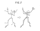
- FIG. 2 is a schematic diagram of an outline of "Method for Generating Posc and Motion of Link System with Tree Construction" the relative invention which forms of the interface used in the method for generating a motion of a human type link system embodying this invention.
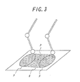
- FIG. 3 is a schematic diagram of the method for determining that the pressure center point exists whether in convex hull of the contact region or not in the method embodying this invention.
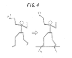
- FIG. 4 is a schematic diagram of contact force and link acceleration, calculation of an actuation spatial inverse inertial matrix based on this force and accelaration in the method embodying this invention.
- The present invention will be further explained below with reference to a preferred embodiment shown in the accompanying drawings. At first, an outline of "Method for Generating Pose and Motion of Link System with Tree Construction", the relative invention whose interface is also used for generating a motion of human type link system in this invention, will be explained. As shown in FIG. 2, in this method, as some of the links in the human type link system (link a, b, c in FIG. 2) are fixed in the space and trajectory of other link (link d in FIG. 2) is designate, whole body motion of robot which the robot moves on the designated trajectory with satisfying the constraint condition of fixed links. In this method, it is also possible to give the robot to not only position of the link but also constraint condition of work space of joint or reference value of joint. However, since this method only takes account of kinematical constraint condition, dynamically infeasible motion may be generated.
- In preferred embodiments of this invention, dynamic feasible motion is generated by taking account of not only kinematical constraint condition as the above-mentioned relative invention, but also dynamic constraint condition such as mass of the link, moment of inertia, torque of joint, and contact force. There are following two method to calculate dynamic constraint condition:
- (A) Method based on inverse dynamics calculation
- (B) Method by using actuation space inverse inertial matrix
-
- Detail of these methods will be described thereinafter.
- This method realizes fast calculation by inverse dynamic calculation with relatively high computing speed and without using dynamic calculation with time-consuming computation. Calculating steps of this method are as follows:
- (a) Calculate objective joint acceleration necessary to satisfy kinematical constraint condition. That is, as above-mentioned method of the relative invention which is only accounting kinematical constraints, calculate joint acceleration which is to be generated at each of joints of the robot from the difference between present status of each joint and the constraint conditions.
- (b) Calculate external force acted from the environment of the robot, such as floor. This force is the factor that is need for generating the reference joint acceleration derived from step (a), so this force is calculated by inverse dynamic calculation. In order to calculate the force needs for generate objective joint acceleration, method of inverse dynamic calculation such as Newton-Euler method.
- (c) Check the external force calculated in step (b) whether this force is
valid as a contact force. The criterion of validity has the following three check
points:
- (1) Is the vertical direction force function as a repulsive force? Because the contact force cannot act on the link as pulling force directed to the floor.
- (2) Is a pressure center point existing in the convex hull of the contact region? As shown in FIG. 3, this pressure center point needs to be included within the convex hull R in the contact region of both bottoms of feet F faced on the floor. In addition, the term "convex hull" is defined as the minimum convex polygon including the contact region and here means the area enclosed by both bottoms of feet of a robot, the virtual line drawn between both of the toes and between both of the heels.
- (3) Is the frictional force less or equal to the maximum static frictional force (at non-slip condition)? In order to maintain a non-slip condition, this frictional force needs to be less or equal to the maximum static frictional force derived from multiplying the vertical reaction force and the coefficient of static friction.
- (d) If the external force is determined to be valid as a reaction force in step (c), the reference joint acceleration is employed directly as the joint acceleration.
- (e) If the external force is determined to be invalid as a reaction force in step (c), recalculate the external force to derive a new valid value of the external force which is nearest to the pre-calculated value and has validity, then, execute the above step (a) to add a new constraint condition so that the value of the external force substitutes to the new corrected value. Subsequently, the recalculated reference joint acceleration under the new constraint condition is employed directly as a new joint acceleration.
-
- Corrective calculation of the external force is executed by the following procedures:
- (1) If the vertical direction force has direction to pull the link, this force sets zero.
- (2) If a pressure center point exists out of the convex hull of the contact region, set the nearest point in the convex hull as a new pressure center point.
- (3) If the frictional force is larger than maximum static frictional force allowed in the same direction as the frictional force, this maximum static frictional force sets as a new frictional force.
-
- If the corrected external force is represented by the vector
ƒ andc ,
so the constraint condition which joint accelerationshould be satisfy is represented by following equation:

- In this equation, Mb, cb, Jcb respectively represents the inertial matrix of a human type link system, velocity and gravity term and coordinate conversion matrix of contact point. Mb and cb can be calculated quickly by executing inverse dynamic calculation repeatedly.
- (f) Obtain joint angle and joint velocity by means of integral calculation of the joint acceleration derived from above step (d) or step (e).
- This method utilizes an actuation space inverse inertial matrix, which represents the relation between force acted on the reference link in a human type link system and the motion of the link. This matrix can be calculated quickly by using the method disclosed in Japanese patent application number 2001-242435 "Method for Generating Pose and Motion of Link System with Tree Construction" which is invented by the same inventor as this application. Calculating steps of this method are as follows:
- (a) Calculate actuation space inverse inertial matrix An actuation space inverse inertial matrix represents the relation between the contact force and the link acceleration consequently generated by the force as shown FIG. 4.
-
- That is, if the actuation space inverse inertial matrix is represented by the symbol
Λi,
so the relation in the acceleration before taking account of the contactthe acceleration after taking account of the contact and the contact force fc is formed by this equation:

- This matrix can be calculated by using the method disclosed in Japanese patent application number 2001-242435.
- (b) Calculate matrix which represents the relation between the joint acceleration and the acceleration of the constrain point when it is not took account for contact. The accelerationwhich was utilized in above step (a) is varied by the inertial force caused by the motion of the joint. Matrix Φi used in following equation is represented as the relation of the acceleration
 and the joint acceleration


- The symbol Φi represents the acceleration of link no. i in the link system when the joint acceleration is zero.
- (c) Calculate contact force from such as floor assuming a spring and a dumper exists in the contact point. As depth of plunging in contact point m represents dm and the velocity of plunging represents Um, the contact force fm is calculated from the following equation.
- In this equation, ks ,kD means coefficient of spring and dumper respectively. As work out the sum of fm at all of the contact point, total contact force fc is obtained.
- (d) Using two matrices calculated at step (a) and (b) and the contact force calculated at step (c), an equation will be derived. This equation represents the relation of the joint acceleration, the link given its trajectory and link acceleration which the link is constrained at its absolute position.
- That is, by the parameteris eliminated from equation at step (a) and (b) respectively and subedit the equations, the following equation is derived.


- This equation gives the relation ofand
 .
.
- With regard to the link with constrained position and the link having its trajectory, since the objective acceleration of these linksis already calculated, so the equation
 which
which is Substituted to
 in the foregoing equation (1) is the constraint condition regarding dynamics.
- (e) Resolving simultaneous equation of the equation in step (d) and the equation of the other dynamic constraint condition such as objective joint values, the joint acceleration is derived.
- With regard to work space of joint and reference joint values, reference acceleration is given asResolving this value and the constraint condition of step (d) simultaneously, the joint acceleration which satisfies both kinematical constraint condition and dynamic constraint condition are obtained.

- (f) Obtain joint angle and joint velocity from integral calculation of the equation which is derived in step (e).
Claims (2)
- A method for generating a motion in a human type link system, wherein,
dynamically feasible motion of the link system is generated when a reference joint acceleration that is only calculated from a kinematic constraint condition is determined not feasible by an evaluation of external force computed based on an inverse dynamics calculation. - A method for generating a motion in a human type link system, wherein,
dynamically feasible motion of the link system is generated by calculating from a dynamic constraint condition and a kinematical constraint condition simultaneously, the dynamic constraint condition is formulated by using an actuation space inverse inertial matrix that represents the relation of force acted on the link system and the acceleration of the link system caused by the said acceleration.
Priority Applications (1)
| Application Number | Priority Date | Filing Date | Title |
|---|---|---|---|
| EP07002408A EP1780679A1 (en) | 2002-02-12 | 2003-02-12 | Method for generating a motion of a human type link system |
Applications Claiming Priority (2)
| Application Number | Priority Date | Filing Date | Title |
|---|---|---|---|
| JP2002034535 | 2002-02-12 | ||
| JP2002034535A JP3790816B2 (en) | 2002-02-12 | 2002-02-12 | Motion generation method for humanoid link system |
Related Child Applications (1)
| Application Number | Title | Priority Date | Filing Date |
|---|---|---|---|
| EP07002408A Division EP1780679A1 (en) | 2002-02-12 | 2003-02-12 | Method for generating a motion of a human type link system |
Publications (3)
| Publication Number | Publication Date |
|---|---|
| EP1334901A2 true EP1334901A2 (en) | 2003-08-13 |
| EP1334901A3 EP1334901A3 (en) | 2006-06-07 |
| EP1334901B1 EP1334901B1 (en) | 2008-01-02 |
Family
ID=27606570
Family Applications (2)
| Application Number | Title | Priority Date | Filing Date |
|---|---|---|---|
| EP07002408A Withdrawn EP1780679A1 (en) | 2002-02-12 | 2003-02-12 | Method for generating a motion of a human type link system |
| EP03250852A Expired - Lifetime EP1334901B1 (en) | 2002-02-12 | 2003-02-12 | Method for generating a motion of a human type link system |
Family Applications Before (1)
| Application Number | Title | Priority Date | Filing Date |
|---|---|---|---|
| EP07002408A Withdrawn EP1780679A1 (en) | 2002-02-12 | 2003-02-12 | Method for generating a motion of a human type link system |
Country Status (7)
| Country | Link |
|---|---|
| US (1) | US7136722B2 (en) |
| EP (2) | EP1780679A1 (en) |
| JP (1) | JP3790816B2 (en) |
| KR (1) | KR100545520B1 (en) |
| CN (1) | CN1249623C (en) |
| CA (1) | CA2418727C (en) |
| DE (1) | DE60318340D1 (en) |
Cited By (3)
| Publication number | Priority date | Publication date | Assignee | Title |
|---|---|---|---|---|
| KR100629431B1 (en) | 2004-12-14 | 2006-09-29 | 한국전자통신연구원 | Mass point location correction method and human-like articulated body animation method using it |
| EP2080596A3 (en) * | 2007-10-19 | 2010-08-04 | Sony Corporation | Control system, control method, and robot apparatus |
| WO2013142997A1 (en) * | 2012-03-29 | 2013-10-03 | Morbi Aliasgar | Control system and device for patient assist |
Families Citing this family (73)
| Publication number | Priority date | Publication date | Assignee | Title |
|---|---|---|---|---|
| US20040064195A1 (en) | 2002-07-15 | 2004-04-01 | Hugh Herr | Variable-mechanical-impedance artificial legs |
| US8075633B2 (en) | 2003-09-25 | 2011-12-13 | Massachusetts Institute Of Technology | Active ankle foot orthosis |
| US7313463B2 (en) * | 2005-03-31 | 2007-12-25 | Massachusetts Institute Of Technology | Biomimetic motion and balance controllers for use in prosthetics, orthotics and robotics |
| US10307272B2 (en) | 2005-03-31 | 2019-06-04 | Massachusetts Institute Of Technology | Method for using a model-based controller for a robotic leg |
| US8512415B2 (en) | 2005-03-31 | 2013-08-20 | Massachusetts Institute Of Technology | Powered ankle-foot prothesis |
| US20070162152A1 (en) | 2005-03-31 | 2007-07-12 | Massachusetts Institute Of Technology | Artificial joints using agonist-antagonist actuators |
| US11278433B2 (en) | 2005-03-31 | 2022-03-22 | Massachusetts Institute Of Technology | Powered ankle-foot prosthesis |
| US8864846B2 (en) | 2005-03-31 | 2014-10-21 | Massachusetts Institute Of Technology | Model-based neuromechanical controller for a robotic leg |
| US20070123997A1 (en) | 2005-03-31 | 2007-05-31 | Massachusetts Institute Of Technology | Exoskeletons for running and walking |
| US8500823B2 (en) | 2005-03-31 | 2013-08-06 | Massachusetts Institute Of Technology | Powered artificial knee with agonist-antagonist actuation |
| US20070043449A1 (en) | 2005-03-31 | 2007-02-22 | Massachusetts Institute Of Technology | Artificial ankle-foot system with spring, variable-damping, and series-elastic actuator components |
| US10080672B2 (en) | 2005-03-31 | 2018-09-25 | Bionx Medical Technologies, Inc. | Hybrid terrain-adaptive lower-extremity systems |
| US20060249315A1 (en) | 2005-03-31 | 2006-11-09 | Massachusetts Institute Of Technology | Artificial human limbs and joints employing actuators, springs, and variable-damper elements |
| US7573477B2 (en) * | 2005-06-17 | 2009-08-11 | Honda Motor Co., Ltd. | System and method for activation-driven muscle deformations for existing character motion |
| JP4682791B2 (en) * | 2005-10-12 | 2011-05-11 | ソニー株式会社 | Operation space physical quantity calculation device, operation space physical quantity calculation method, and computer program |
| KR100920056B1 (en) | 2006-12-04 | 2009-10-07 | 한국전자통신연구원 | Apparatus for capturing and editing pose data or motion data by constructing articulated figures and method thereof |
| US20080221487A1 (en) * | 2007-03-07 | 2008-09-11 | Motek Bv | Method for real time interactive visualization of muscle forces and joint torques in the human body |
| WO2008135863A2 (en) * | 2007-05-03 | 2008-11-13 | Motek Bv | Method and system for real tlme interactive dynamic alignment of prosthetics |
| US20100174384A1 (en) | 2008-09-04 | 2010-07-08 | Iwalk, Inc. | Hybrid terrain-adaptive lower-extremity systems |
| US20110082566A1 (en) | 2008-09-04 | 2011-04-07 | Herr Hugh M | Implementing a stand-up sequence using a lower-extremity prosthesis or orthosis |
| US8199151B2 (en) * | 2009-02-13 | 2012-06-12 | Naturalmotion Ltd. | Animation events |
| JP5836565B2 (en) * | 2009-03-24 | 2015-12-24 | ディズニー エンタープライゼス インコーポレイテッド | Robot tracking and balancing system and method for mimicking motion capture data |
| JP2013524880A (en) | 2010-04-05 | 2013-06-20 | アイウォーク, インコーポレイテッド | Torque control in a prosthesis or brace |
| US20110267357A1 (en) * | 2010-04-29 | 2011-11-03 | Rennuit Antoine Felix Robert | Animating a virtual object within a virtual world |
| US8676382B2 (en) | 2010-05-26 | 2014-03-18 | GM Global Technology Operations LLC | Applying workspace limitations in a velocity-controlled robotic mechanism |
| WO2012096956A1 (en) | 2011-01-10 | 2012-07-19 | Iwalk, Inc. | Powered joint orthosis |
| US20120259430A1 (en) | 2011-01-12 | 2012-10-11 | Zhixiu Han | Controlling powered human augmentation devices |
| US9687377B2 (en) | 2011-01-21 | 2017-06-27 | Bionx Medical Technologies, Inc. | Terrain adaptive powered joint orthosis |
| WO2012125562A1 (en) | 2011-03-11 | 2012-09-20 | Iwalk, Inc. | Biomimetic joint actuators |
| US9566710B2 (en) | 2011-06-02 | 2017-02-14 | Brain Corporation | Apparatus and methods for operating robotic devices using selective state space training |
| JP5907678B2 (en) * | 2011-07-20 | 2016-04-26 | オリンパス株式会社 | Medical operating mechanism and manipulator |
| WO2013067407A1 (en) | 2011-11-02 | 2013-05-10 | Iwalk, Inc. | Biomimetic transfemoral prosthesis |
| WO2013069291A1 (en) * | 2011-11-10 | 2013-05-16 | パナソニック株式会社 | Robot, and control device, control method and control program for robot |
| US9032635B2 (en) | 2011-12-15 | 2015-05-19 | Massachusetts Institute Of Technology | Physiological measurement device or wearable device interface simulator and method of use |
| US9221177B2 (en) | 2012-04-18 | 2015-12-29 | Massachusetts Institute Of Technology | Neuromuscular model-based sensing and control paradigm for a robotic leg |
| US10531965B2 (en) | 2012-06-12 | 2020-01-14 | Bionx Medical Technologies, Inc. | Prosthetic, orthotic or exoskeleton device |
| CN103019096B (en) * | 2012-11-23 | 2015-09-16 | 北京理工大学 | A kind of anthropomorphic robot inverse metabolic engineering device optimized based on acceleration |
| CN103853043B (en) * | 2012-11-30 | 2017-02-22 | 北京配天技术有限公司 | Method for realizing synchronous PTP motion in robots and device thereof |
| US9764468B2 (en) | 2013-03-15 | 2017-09-19 | Brain Corporation | Adaptive predictor apparatus and methods |
| US9242372B2 (en) | 2013-05-31 | 2016-01-26 | Brain Corporation | Adaptive robotic interface apparatus and methods |
| US9384443B2 (en) | 2013-06-14 | 2016-07-05 | Brain Corporation | Robotic training apparatus and methods |
| US9792546B2 (en) | 2013-06-14 | 2017-10-17 | Brain Corporation | Hierarchical robotic controller apparatus and methods |
| US9314924B1 (en) | 2013-06-14 | 2016-04-19 | Brain Corporation | Predictive robotic controller apparatus and methods |
| US9579789B2 (en) | 2013-09-27 | 2017-02-28 | Brain Corporation | Apparatus and methods for training of robotic control arbitration |
| US9597797B2 (en) | 2013-11-01 | 2017-03-21 | Brain Corporation | Apparatus and methods for haptic training of robots |
| US9463571B2 (en) | 2013-11-01 | 2016-10-11 | Brian Corporation | Apparatus and methods for online training of robots |
| US9358685B2 (en) * | 2014-02-03 | 2016-06-07 | Brain Corporation | Apparatus and methods for control of robot actions based on corrective user inputs |
| EP2933067B1 (en) * | 2014-04-17 | 2019-09-18 | Softbank Robotics Europe | Method of performing multi-modal dialogue between a humanoid robot and user, computer program product and humanoid robot for implementing said method |
| US9346167B2 (en) | 2014-04-29 | 2016-05-24 | Brain Corporation | Trainable convolutional network apparatus and methods for operating a robotic vehicle |
| US9630318B2 (en) | 2014-10-02 | 2017-04-25 | Brain Corporation | Feature detection apparatus and methods for training of robotic navigation |
| US9717387B1 (en) | 2015-02-26 | 2017-08-01 | Brain Corporation | Apparatus and methods for programming and training of robotic household appliances |
| US10471594B2 (en) * | 2015-12-01 | 2019-11-12 | Kindred Systems Inc. | Systems, devices, and methods for the distribution and collection of multimodal data associated with robots |
| DE102017000063B4 (en) * | 2016-01-14 | 2019-10-31 | Fanuc Corporation | Robot device with learning function |
| CN105717869B (en) * | 2016-03-15 | 2018-05-29 | 珞石(北京)科技有限公司 | Industrial robot operating space path Mixed Circumscription method for solving |
| US10241514B2 (en) | 2016-05-11 | 2019-03-26 | Brain Corporation | Systems and methods for initializing a robot to autonomously travel a trained route |
| US9987752B2 (en) | 2016-06-10 | 2018-06-05 | Brain Corporation | Systems and methods for automatic detection of spills |
| CN106113034B (en) * | 2016-06-12 | 2018-06-12 | 哈尔滨工程大学 | A kind of sixdegree-of-freedom simulation considers the method for planning track of force constraint |
| US10282849B2 (en) | 2016-06-17 | 2019-05-07 | Brain Corporation | Systems and methods for predictive/reconstructive visual object tracker |
| US10016896B2 (en) | 2016-06-30 | 2018-07-10 | Brain Corporation | Systems and methods for robotic behavior around moving bodies |
| US10274325B2 (en) | 2016-11-01 | 2019-04-30 | Brain Corporation | Systems and methods for robotic mapping |
| US10001780B2 (en) | 2016-11-02 | 2018-06-19 | Brain Corporation | Systems and methods for dynamic route planning in autonomous navigation |
| US10723018B2 (en) | 2016-11-28 | 2020-07-28 | Brain Corporation | Systems and methods for remote operating and/or monitoring of a robot |
| US10377040B2 (en) | 2017-02-02 | 2019-08-13 | Brain Corporation | Systems and methods for assisting a robotic apparatus |
| US10852730B2 (en) | 2017-02-08 | 2020-12-01 | Brain Corporation | Systems and methods for robotic mobile platforms |
| US10293485B2 (en) | 2017-03-30 | 2019-05-21 | Brain Corporation | Systems and methods for robotic path planning |
| CN107263466B (en) * | 2017-05-11 | 2020-07-17 | 西北工业大学 | Base undisturbed control method of space robot based on quadratic programming problem |
| CN107520844B (en) * | 2017-09-21 | 2019-09-24 | 西北工业大学 | Space manipulator arrests the polyhedron crash dynamics analysis method of noncooperative target |
| KR102228866B1 (en) * | 2018-10-18 | 2021-03-17 | 엘지전자 주식회사 | Robot and method for controlling thereof |
| CN109634100B (en) * | 2018-12-30 | 2021-11-02 | 深圳市优必选科技有限公司 | Humanoid robot walking acceleration compensation method and device and humanoid robot |
| CN111872941B (en) * | 2020-08-06 | 2021-09-07 | 深圳市优必选科技股份有限公司 | Balance control method and device, humanoid robot and readable storage medium |
| CN112050805B (en) * | 2020-09-02 | 2021-07-27 | 上海高仙自动化科技发展有限公司 | Path planning method and device, electronic equipment and storage medium |
| CN112847336B (en) * | 2020-12-24 | 2023-08-22 | 达闼机器人股份有限公司 | Action learning method and device, storage medium and electronic equipment |
| DE102021112485B3 (en) | 2021-05-12 | 2022-08-11 | Deutsches Zentrum für Luft- und Raumfahrt e.V. | Method for balancing a robot, method for whole-body control of a robot, regulator and robot |
Family Cites Families (15)
| Publication number | Priority date | Publication date | Assignee | Title |
|---|---|---|---|---|
| JPH0584679A (en) | 1990-12-25 | 1993-04-06 | Kongouzen Souhonzan Shiyourinji | Robot programming method |
| US5276390A (en) * | 1991-10-04 | 1994-01-04 | Hewlett-Packard Company | System for hybrid position and force control |
| US5377310A (en) * | 1992-04-03 | 1994-12-27 | The United States Of America As Represented By The Administrator Of The National Aeronautics And Space Administration | Controlling under-actuated robot arms using a high speed dynamics |
| US5594856A (en) * | 1994-08-25 | 1997-01-14 | Girard; Michael | Computer user interface for step-driven character animation |
| US6144385A (en) * | 1994-08-25 | 2000-11-07 | Michael J. Girard | Step-driven character animation derived from animation data without footstep information |
| US5644204A (en) * | 1994-11-03 | 1997-07-01 | Nagle; John | Anti-slip control for a legged robot and realisitc simulation of a legged creature |
| JP3369351B2 (en) * | 1995-03-28 | 2003-01-20 | 富士通株式会社 | Elasticity setting method and control device for articulated manipulator |
| US5808433A (en) * | 1995-09-29 | 1998-09-15 | Honda Giken Kogyo Kabushiki Kaisha | Method of generating gait of legged walking robot and system for controlling its locomotion |
| US5872893A (en) * | 1996-07-25 | 1999-02-16 | Honda Giken Kogyo Kabushiki Kaisha | Gait generation system of legged mobile robot |
| US6104412A (en) * | 1996-08-21 | 2000-08-15 | Nippon Telegraph And Telephone Corporation | Method for generating animations of a multi-articulated structure, recording medium having recorded thereon the same and animation generating apparatus using the same |
| EP0965416B1 (en) * | 1996-12-19 | 2005-12-07 | Honda Giken Kogyo Kabushiki Kaisha | Attitude controller of legged moving robot |
| JP3672426B2 (en) | 1996-12-19 | 2005-07-20 | 本田技研工業株式会社 | Posture control device for legged mobile robot |
| US6057620A (en) * | 1999-04-28 | 2000-05-02 | Precision Instrument Development Center | Geometrical structure configuration of maglev forces in a maglev rotational bearing apparatus |
| JP3555107B2 (en) * | 1999-11-24 | 2004-08-18 | ソニー株式会社 | Legged mobile robot and operation control method for legged mobile robot |
| JP2001242435A (en) | 2000-02-25 | 2001-09-07 | Hitachi Ltd | Liquid crystal multi-display device |
-
2002
- 2002-02-12 JP JP2002034535A patent/JP3790816B2/en not_active Expired - Lifetime
-
2003
- 2003-02-10 US US10/360,873 patent/US7136722B2/en not_active Expired - Fee Related
- 2003-02-11 CA CA002418727A patent/CA2418727C/en not_active Expired - Fee Related
- 2003-02-12 KR KR1020030008752A patent/KR100545520B1/en not_active IP Right Cessation
- 2003-02-12 DE DE60318340T patent/DE60318340D1/en not_active Expired - Lifetime
- 2003-02-12 EP EP07002408A patent/EP1780679A1/en not_active Withdrawn
- 2003-02-12 CN CNB031038239A patent/CN1249623C/en not_active Expired - Fee Related
- 2003-02-12 EP EP03250852A patent/EP1334901B1/en not_active Expired - Lifetime
Non-Patent Citations (4)
| Title |
|---|
| ISAACS P M , COHEN M F: "CONTROLLING DYNAMIC SIMULATION WITH KINEMATIC CONSTRAINTS, BEHAVIOR FUNCTIONS AND INVERSE DYNAMICS" SIGGRAPH '87 CONF PROC, vol. 21, no. 4, July 1987 (1987-07), pages 215-224, XP002374049 Anaheim, CA, USA * |
| KO H ET AL: "ANIMATING HUMAN LOCOMOTION WITH INVERSE DYNAMICS" IEEE COMPUTER GRAPHICS AND APPLICATIONS, IEEE SERVICE CENTER, NEW YORK, NY, US, vol. 16, no. 2, March 1996 (1996-03), pages 50-59, XP000936422 ISSN: 0272-1716 * |
| LILLY K W, ORIN D E: "Efficient O(N) computation of the operational space inertia matrix" IEEE TRANSACTION ON SYSTEMS, MAN AND CYBERNETICS, vol. 23, no. 5, September 1993 (1993-09), pages 1384-1391, XP000417064 * |
| MULTON F ET AL: "COMPUTER ANIMATION OF HUMAN WALKING: A SURVEY" JOURNAL OF VISUALIZATION AND COMPUTER ANIMATION, vol. 10, no. 1, January 1999 (1999-01), pages 39-54, XP001059489 * |
Cited By (6)
| Publication number | Priority date | Publication date | Assignee | Title |
|---|---|---|---|---|
| KR100629431B1 (en) | 2004-12-14 | 2006-09-29 | 한국전자통신연구원 | Mass point location correction method and human-like articulated body animation method using it |
| EP2080596A3 (en) * | 2007-10-19 | 2010-08-04 | Sony Corporation | Control system, control method, and robot apparatus |
| US8463433B2 (en) | 2007-10-19 | 2013-06-11 | Sony Corporation | Control system, control method, and robot apparatus |
| WO2013142997A1 (en) * | 2012-03-29 | 2013-10-03 | Morbi Aliasgar | Control system and device for patient assist |
| US9907721B2 (en) | 2012-03-29 | 2018-03-06 | GaitTronics inc. | Control system and device for patient assist |
| US10251805B2 (en) | 2012-03-29 | 2019-04-09 | GaitTronics inc. | Control system and device for patient assist |
Also Published As
| Publication number | Publication date |
|---|---|
| CA2418727C (en) | 2008-06-03 |
| CN1487469A (en) | 2004-04-07 |
| JP2003231077A (en) | 2003-08-19 |
| EP1334901B1 (en) | 2008-01-02 |
| CA2418727A1 (en) | 2003-08-12 |
| EP1334901A3 (en) | 2006-06-07 |
| US7136722B2 (en) | 2006-11-14 |
| EP1780679A1 (en) | 2007-05-02 |
| JP3790816B2 (en) | 2006-06-28 |
| CN1249623C (en) | 2006-04-05 |
| US20030220714A1 (en) | 2003-11-27 |
| KR20030068443A (en) | 2003-08-21 |
| KR100545520B1 (en) | 2006-01-24 |
| DE60318340D1 (en) | 2008-02-14 |
Similar Documents
| Publication | Publication Date | Title |
|---|---|---|
| US7136722B2 (en) | Method for generating a motion of a human type link system | |
| JP4682791B2 (en) | Operation space physical quantity calculation device, operation space physical quantity calculation method, and computer program | |
| Yamane et al. | Simultaneous tracking and balancing of humanoid robots for imitating human motion capture data | |
| Nakamura et al. | Dynamics computation of structure-varying kinematic chains and its application to human figures | |
| JP5034235B2 (en) | Control system, control method, and computer program | |
| Li et al. | Force-and-moment-based model predictive control for achieving highly dynamic locomotion on bipedal robots | |
| Otani et al. | Adaptive whole-body manipulation in human-to-humanoid multi-contact motion retargeting | |
| JP2004030502A (en) | Simulation method, simulation apparatus, and simulation program | |
| Nikolić et al. | Dynamic balance preservation and prevention of sliding for humanoid robots in the presence of multiple spatial contacts | |
| JP3944566B2 (en) | A method of dynamically determining joint acceleration in a link mechanism. | |
| JP5099733B2 (en) | Control device for legged mobile robot | |
| Cisneros et al. | Partial yaw moment compensation using an optimization-based multi-objective motion solver | |
| Huang et al. | Approach trajectory planning of space robot for impact minimization | |
| Vasilopoulos et al. | Control and energy considerations for a hopping monopod on rough compliant terrains | |
| Li et al. | Iterative calculation method for constraint motion by extended newton-euler method and application for forward dynamics | |
| Nagurka | Newton-Euler dynamics of robots | |
| Wang et al. | Multi-contact Stability of Humanoids using ZMP and CWC | |
| Yilmaz et al. | Circular arc-shaped walking trajectory generation for bipedal humanoid robots | |
| Andrjejew et al. | Development the algorithms of anthropomorphic robot's motion control by use of AI algorithms | |
| Sulaiman et al. | DeNOC based dynamic modelling of a tree type humanoid upper-body robot with fixed base | |
| Nakamura et al. | Interactive motion generation of humanoid robots via dynamics filter | |
| KR101289785B1 (en) | System for generating optimal trajectory of robot manipulator that minimized the joint torque variation and method therefor | |
| Abiko et al. | Computational efficient algorithms for operational space formulation of branching arms on a space robot | |
| Gay et al. | Model-based and model-free approaches for postural control of a compliant humanoid robot using optical flow | |
| Fijany et al. | A new algorithmic framework for robot dynamics analysis with application to space robots dynamics simulation |
Legal Events
| Date | Code | Title | Description |
|---|---|---|---|
| PUAI | Public reference made under article 153(3) epc to a published international application that has entered the european phase |
Free format text: ORIGINAL CODE: 0009012 |
|
| 17P | Request for examination filed |
Effective date: 20030312 |
|
| AK | Designated contracting states |
Designated state(s): AT BE BG CH CY CZ DE DK EE ES FI FR GB GR HU IE IT LI LU MC NL PT SE SI SK TR |
|
| AX | Request for extension of the european patent |
Extension state: AL LT LV MK RO |
|
| PUAL | Search report despatched |
Free format text: ORIGINAL CODE: 0009013 |
|
| RIC1 | Information provided on ipc code assigned before grant |
Ipc: B25J 9/16 20060101ALI20060327BHEP Ipc: B62D 57/032 20060101ALI20060327BHEP Ipc: G06T 15/70 20060101AFI20060327BHEP |
|
| AK | Designated contracting states |
Kind code of ref document: A3 Designated state(s): AT BE BG CH CY CZ DE DK EE ES FI FR GB GR HU IE IT LI LU MC NL PT SE SI SK TR |
|
| AX | Request for extension of the european patent |
Extension state: AL LT LV MK RO |
|
| 17Q | First examination report despatched |
Effective date: 20060928 |
|
| AKX | Designation fees paid |
Designated state(s): DE FR GB IT |
|
| GRAP | Despatch of communication of intention to grant a patent |
Free format text: ORIGINAL CODE: EPIDOSNIGR1 |
|
| GRAS | Grant fee paid |
Free format text: ORIGINAL CODE: EPIDOSNIGR3 |
|
| RIN1 | Information on inventor provided before grant (corrected) |
Inventor name: TANGE, MANABU Inventor name: YAMANE, KATSU Inventor name: NAKAMURA, YOSHIHIKO |
|
| GRAA | (expected) grant |
Free format text: ORIGINAL CODE: 0009210 |
|
| RAP1 | Party data changed (applicant data changed or rights of an application transferred) |
Owner name: THE UNIVERSITY OF TOKYO |
|
| AK | Designated contracting states |
Kind code of ref document: B1 Designated state(s): DE FR GB IT |
|
| REG | Reference to a national code |
Ref country code: GB Ref legal event code: FG4D |
|
| REF | Corresponds to: |
Ref document number: 60318340 Country of ref document: DE Date of ref document: 20080214 Kind code of ref document: P |
|
| EN | Fr: translation not filed | ||
| PG25 | Lapsed in a contracting state [announced via postgrant information from national office to epo] |
Ref country code: DE Free format text: LAPSE BECAUSE OF FAILURE TO SUBMIT A TRANSLATION OF THE DESCRIPTION OR TO PAY THE FEE WITHIN THE PRESCRIBED TIME-LIMIT Effective date: 20080403 |
|
| PLBE | No opposition filed within time limit |
Free format text: ORIGINAL CODE: 0009261 |
|
| STAA | Information on the status of an ep patent application or granted ep patent |
Free format text: STATUS: NO OPPOSITION FILED WITHIN TIME LIMIT |
|
| 26N | No opposition filed |
Effective date: 20081003 |
|
| GBPC | Gb: european patent ceased through non-payment of renewal fee |
Effective date: 20080402 |
|
| PG25 | Lapsed in a contracting state [announced via postgrant information from national office to epo] |
Ref country code: FR Free format text: LAPSE BECAUSE OF FAILURE TO SUBMIT A TRANSLATION OF THE DESCRIPTION OR TO PAY THE FEE WITHIN THE PRESCRIBED TIME-LIMIT Effective date: 20081024 |
|
| PG25 | Lapsed in a contracting state [announced via postgrant information from national office to epo] |
Ref country code: GB Free format text: LAPSE BECAUSE OF NON-PAYMENT OF DUE FEES Effective date: 20080402 |
|
| PG25 | Lapsed in a contracting state [announced via postgrant information from national office to epo] |
Ref country code: IT Free format text: LAPSE BECAUSE OF FAILURE TO SUBMIT A TRANSLATION OF THE DESCRIPTION OR TO PAY THE FEE WITHIN THE PRESCRIBED TIME-LIMIT Effective date: 20080102 |