EP1334833A2 - Maintenance module for fluid jet device and said fluid jet device - Google Patents
Maintenance module for fluid jet device and said fluid jet device Download PDFInfo
- Publication number
- EP1334833A2 EP1334833A2 EP03290279A EP03290279A EP1334833A2 EP 1334833 A2 EP1334833 A2 EP 1334833A2 EP 03290279 A EP03290279 A EP 03290279A EP 03290279 A EP03290279 A EP 03290279A EP 1334833 A2 EP1334833 A2 EP 1334833A2
- Authority
- EP
- European Patent Office
- Prior art keywords
- plate
- maintenance module
- orifices
- accordance
- longitudinal axis
- Prior art date
- Legal status (The legal status is an assumption and is not a legal conclusion. Google has not performed a legal analysis and makes no representation as to the accuracy of the status listed.)
- Granted
Links
- 238000012423 maintenance Methods 0.000 title claims abstract description 54
- 239000012530 fluid Substances 0.000 title claims abstract description 43
- 239000011248 coating agent Substances 0.000 claims description 5
- 238000000576 coating method Methods 0.000 claims description 5
- 229920000642 polymer Polymers 0.000 claims description 2
- 239000000853 adhesive Substances 0.000 description 4
- 230000001070 adhesive effect Effects 0.000 description 4
- 238000000034 method Methods 0.000 description 4
- 238000010926 purge Methods 0.000 description 3
- 239000000758 substrate Substances 0.000 description 3
- 239000002184 metal Substances 0.000 description 2
- 229920006362 Teflon® Polymers 0.000 description 1
- 238000004140 cleaning Methods 0.000 description 1
- 230000000694 effects Effects 0.000 description 1
- 229920002313 fluoropolymer Polymers 0.000 description 1
- 239000004811 fluoropolymer Substances 0.000 description 1
- 239000000463 material Substances 0.000 description 1
- 230000000116 mitigating effect Effects 0.000 description 1
- 230000037452 priming Effects 0.000 description 1
- 239000011347 resin Substances 0.000 description 1
- 229920005989 resin Polymers 0.000 description 1
- 229910001220 stainless steel Inorganic materials 0.000 description 1
- 239000010935 stainless steel Substances 0.000 description 1
Images
Classifications
-
- B—PERFORMING OPERATIONS; TRANSPORTING
- B41—PRINTING; LINING MACHINES; TYPEWRITERS; STAMPS
- B41J—TYPEWRITERS; SELECTIVE PRINTING MECHANISMS, i.e. MECHANISMS PRINTING OTHERWISE THAN FROM A FORME; CORRECTION OF TYPOGRAPHICAL ERRORS
- B41J2/00—Typewriters or selective printing mechanisms characterised by the printing or marking process for which they are designed
- B41J2/005—Typewriters or selective printing mechanisms characterised by the printing or marking process for which they are designed characterised by bringing liquid or particles selectively into contact with a printing material
- B41J2/01—Ink jet
- B41J2/135—Nozzles
- B41J2/165—Prevention or detection of nozzle clogging, e.g. cleaning, capping or moistening for nozzles
- B41J2/16517—Cleaning of print head nozzles
- B41J2/1652—Cleaning of print head nozzles by driving a fluid through the nozzles to the outside thereof, e.g. by applying pressure to the inside or vacuum at the outside of the print head
- B41J2/16532—Cleaning of print head nozzles by driving a fluid through the nozzles to the outside thereof, e.g. by applying pressure to the inside or vacuum at the outside of the print head by applying vacuum only
-
- B—PERFORMING OPERATIONS; TRANSPORTING
- B41—PRINTING; LINING MACHINES; TYPEWRITERS; STAMPS
- B41J—TYPEWRITERS; SELECTIVE PRINTING MECHANISMS, i.e. MECHANISMS PRINTING OTHERWISE THAN FROM A FORME; CORRECTION OF TYPOGRAPHICAL ERRORS
- B41J2/00—Typewriters or selective printing mechanisms characterised by the printing or marking process for which they are designed
- B41J2/005—Typewriters or selective printing mechanisms characterised by the printing or marking process for which they are designed characterised by bringing liquid or particles selectively into contact with a printing material
- B41J2/01—Ink jet
- B41J2/135—Nozzles
- B41J2/14—Structure thereof only for on-demand ink jet heads
- B41J2/1433—Structure of nozzle plates
Definitions
- the present invention relates generally to fluid jet devices. More particularly, the present invention pertains to fluid jet devices, such as ink jet print systems and maintenance modules configured for mounting to an ink jet print system print head.
- Fluid jet devices are in wide spread use.
- One particular use for such a device is in ink jet printers.
- One type of printer relies upon capillary action to move a working fluid (e.g., ink) to the print head.
- the ink is directed from the print head through one or more orifices toward a target substrate.
- Ink jet printers include an actuator for urging the ink through the orifice.
- Actuators can include piezzo electric elements, thermal devices and the like.
- An exemplary ink jet print head is disclosed in U.S. Patent No. 4,418,355.
- the print head includes a fluid passageway or chamber configured for ink flow from a source to the actuator, and through the orifices.
- ink is present in the passageway or chamber.
- Actuation of the actuator draws ink into the passageway through the actuator and out through the orifices.
- air which can enter the fluid chamber (through the orifices) or dirt or debris that can become lodged in the orifices, results in improper operation of the fluid jet device. Air and debris can result in reduced ink drawn into the flow passageway and subsequently cause the failure to eject ink through the orifices.
- the ink flow passageway or chamber must be devoid of air and dirt or debris and that the passageway must remain filled with ink.
- a number of devices, configurations and methods have been proposed and are used to prevent improper operation of the print head either by preventing air entrainment in the ink or by preventing debris from gathering at the orifices. Some of these configurations and methods are directed to preventing the entrainment of air and collection of debris, while other configurations and methods are directed to mitigating the effects of air entrainment and debris. Still others are directed to removing air that may have already been entrained in the system, or by removing debris that may have already collected at the orifices.
- a maintenance module for a fluid jet device having a straight-forward and simple design.
- a maintenance module facilitates the collection of purge fluid from the fluid jet device used to entrained air and debris that may have collected on the jet device.
- a maintenance module incorporates provisions for drawing a vacuum at the fluid jet device to remove fluid that may have been ejected from the device during the purge cycle.
- a maintenance module is mounted to the front of a fluid jet device to facilitate maintaining the front of the device in a clean state.
- the module includes first and second plates affixed to one another.
- the plates define a longitudinal axis and a transverse axis perpendicular to the longitudinal axis.
- the first or rear plate is a chamber plate/orifice plate that overlies the fluid chamber of the fluid jet device.
- the first plate has a plurality of orifices formed therein.
- the first plate has to parallel rows of closely spaced orifices.
- the orifices extend parallel to the longitudinal axis inwardly of longitudinal edges of the plate.
- the first plate includes a vacuum opening formed therein at about a transverse edge of the first plate.
- the vacuum opening is preferably formed along the longitudinal axis and extends into the plate, perpendicular to a plane defined by the longitudinal and transverse axes.
- the vacuum opening has inwardly tapered walls.
- the first plate can include a plurality of mounting openings extending along opposing longitudinal edges of the plate inwardly of the edges.
- the mounting openings are formed parallel to the longitudinal axis and spaced outwardly of the orifices.
- the first plate can include a flange extending about a periphery thereof.
- the second plate is affixed to and preferably bonded to the first plate.
- the second plate has an elongated channel therein extending over the first plate orifices so that the orifices are exposed through the elongated channel.
- the channel is defined by opposing longitudinal edges extending parallel to the longitudinal axis and preferably formed symmetrically about the longitudinal axis.
- the channel has tapered edges at about an end thereof.
- the tapered edges converge to an arcuate funneling region.
- the second plate overlies the first plate such that the funneling region extends along an edge of the vacuum opening.
- the second plate includes a plurality of fastener openings that correspond to and align over the first plate mounting openings.
- the maintenance module can include orienting notches formed in the first and second plates that align with one another.
- orienting notch is formed through the first plate up to but exclusive of the flange.
- the maintenance module can be formed with the second plate having a polymer coating thereon.
- the coating facilitates maintaining the plate in a clean condition.
- a maintenance module 10 mounted to an exemplary fluid jet device 12, such as the illustrated print head.
- the present maintenance module 10 can be used with any fluid jet device 12, including inkjet print heads, adhesive jetting devices and the like, without limitation.
- the print head 12 includes a plurality of actuators (not shown) that, upon actuation, eject or push a fluid therefrom. The fluid exits the device through a plurality of orifices on a front plate (not shown).
- the maintenance module 10 is mounted to the front of the fluid jet device 12.
- the maintenance module 10 includes a rear plate 14 referred to as a chamber plate/orifice plate.
- the rear plate 14 is an elongated member that defines a major axis (or longitudinal axis) 16 and a minor axis (or transverse axis) 18.
- the rear plate 14 includes a plurality of mounting holes 20 extending adjacent and parallel to each of the elongated edges 22a,b of the plate 14, parallel to the major axis 16.
- the mounting holes 20 are counter-bored or tapered, as indicated at 24, to permit mounting the maintenance module 10 to the fluid jet device 12 so that the fasteners (not shown) that are used to mount the module 10 are flush (or recessed) relative to the module 10.
- the plate 14 includes a plurality of orifices 26 formed longitudinally along the plate 14 generally at a center thereof. In a present embodiment, two parallel rows of orifices 26a,b are formed in the plate 14 parallel to the longitudinal axis 16. The orifices 26a,b provide a flow path for fluid that is ejected from the actuators onto the substrate.
- the rear plate 14 includes a vacuum opening 28 formed therein at about, and inwardly of one of the minor or transverse edges 30.
- the vacuum opening 28 is formed inwardly of the edge 30, between the major or longitudinal edges 22a,b (essentially along the longitudinal axis 16).
- the vacuum opening 28 is formed having a chamfered or tapered edge, as indicated 32. That is, the angle formed between the rear plate surface 34 and the opening 28 is less than 90 degrees (eliminating a sharp angle at the edge).
- the rear plate 14 further includes a rear or mounting flange 36.
- the flange 36 is formed as part of or integral with the rear plate 14.
- the rear plate 14 is formed from a rigid material, such as a metal to provide structural integrity and strength to the module 10.
- a notch 38 can be formed in the rear plate 14, along one of the major edges 22a. The notch 38 facilitates properly orienting the module 10 on the print head 12. In a current embodiment, the notch 38 extends through a front portion of the plate 14, but does not extend into the rear flange 36.
- the maintenance module 10 includes a maintenance plate or front plate 40 mounted to the rear plate 14.
- the maintenance plate 40 includes a plurality of fastener openings 42 extending inwardly of and parallel to longitudinal edges 44a,b of the plate 40.
- the maintenance plate fastener openings 42 correspond to the rear plate mounting openings 20.
- the fastener openings 42 are through-openings, rather than counter-bored. This also facilitates flush (or a low surface) mounting of the fasteners (not shown) that are used to mount the maintenance module 10 to the fluid jet head 12.
- the maintenance plate 40 can include a notch 46 that corresponds to the rear plate notch 38. Again, this notch 46 is used to assure properly orienting the module 10 on the print head 12.
- An elongated central channel 48 is formed in the maintenance plate 40.
- the central charnel 48 is formed interior of (between) the fastener openings 42 and extends longitudinally along the maintenance plate 40 to fully expose the rear plate orifices 26.
- the channel 48 is formed by a pair of generally parallel and spaced edges 50a,b that, at one end (as indicated at 50c), are joined by a semi-circular edge 52 and at an opposing end (as indicated at 50d, overlying the vacuum opening 28), taper toward one another, terminating at an arcuate central region 50e.
- the arcuate central region 50e defines a funneling region that terminates over the vacuum opening 28 in the rear plate 14.
- the channel edge tapers facilitate directing fluid that is expelled from the orifices 26 but is not jetted on to a substrate.
- the channel edges 50a,b, the taper 50d and the funneling region 50e help to direct fluid (e.g., ink) to the vacuum opening 28 when ink drips from the orifices 26 or if ink is expelled from the orifices 26 during, for example, a purge or priming cycle.
- the various tapers in the maintenance plate channel 50d,e and the chamber plate/orifice plate vacuum opening as at 32
- the x-axis oriented parallel to the rear plate transverse or minor axis 18
- the y-axis oriented parallel to the rear plate longitudinal or major axis 16
- the z-axis oriented perpendicular to the plate 14, into the plane defined by the x- and y-axes.
- the maintenance plate channel edges as at 50d taper inwardly (toward one another) in the y-axis direction
- the rear plate vacuum opening edges as at 32 taper inwardly in the z-axis direction.
- This multi-directional taper has been found to facilitate directing fluid that is in the channel 48 toward and into the vacuum opening 28, rather than merely accumulating at the base of the channel 48 in the tapered region (as at 50d). It has been observed that this greatly facilitates the removal or vacuuming away of any fluid that may drip down the front of the chamber plate/orifice plate 14 within the maintenance plate channel 48.
- the maintenance plate 40 is formed from a metal, preferably, a stainless steel. However, the plate 40 is a relatively thin element. To this end, the maintenance plate 40 is preferably bonded to the rear plate 14 by, for example, an adhesive. The adhesive should be applied so as to prevent exposure of the adhesive within or near any of the orifices 26. It has also been found that a coating (as indicated at 54) can be applied to the outer surface of the maintenance plate 40. For example, a coating 54 of a fluoropolymer resin, such as TEFLON ® can be applied to the maintenance plate 40 to facilitate cleaning the plate, 40 and maintaining the plate 40 free of debris.
- a fluoropolymer resin such as TEFLON ®
- present fluid jet device 12 and maintenance module 10 are shown in a vertical orientation (that is, with the longitudinal axis 16 vertical), those skilled in the art will recognize that the present module 10 can be configured for mounting to a jet device that is oriented horizontally or at an angle between the vertical and the horizontal, without departing from the scope and spirit of the present invention.
Landscapes
- Particle Formation And Scattering Control In Inkjet Printers (AREA)
- Surgical Instruments (AREA)
- Ink Jet (AREA)
- Automatic Analysis And Handling Materials Therefor (AREA)
- Treatment Of Water By Ion Exchange (AREA)
- External Artificial Organs (AREA)
- Sampling And Sample Adjustment (AREA)
- Coating Apparatus (AREA)
- Jet Pumps And Other Pumps (AREA)
- Medical Preparation Storing Or Oral Administration Devices (AREA)
Abstract
Description
- The present invention relates generally to fluid jet devices. More particularly, the present invention pertains to fluid jet devices, such as ink jet print systems and maintenance modules configured for mounting to an ink jet print system print head.
- Fluid jet devices are in wide spread use. One particular use for such a device is in ink jet printers. There are a number of principle types of ink jet printers. One type of printer relies upon capillary action to move a working fluid (e.g., ink) to the print head. The ink is directed from the print head through one or more orifices toward a target substrate. Ink jet printers include an actuator for urging the ink through the orifice. Actuators can include piezzo electric elements, thermal devices and the like. An exemplary ink jet print head is disclosed in U.S. Patent No. 4,418,355.
- Typically, the print head includes a fluid passageway or chamber configured for ink flow from a source to the actuator, and through the orifices. During normal operation of the print head, ink is present in the passageway or chamber. Actuation of the actuator draws ink into the passageway through the actuator and out through the orifices. It has, however, been found that air, which can enter the fluid chamber (through the orifices) or dirt or debris that can become lodged in the orifices, results in improper operation of the fluid jet device. Air and debris can result in reduced ink drawn into the flow passageway and subsequently cause the failure to eject ink through the orifices. Thus, it has been found that for effective operation of the print head, the ink flow passageway or chamber must be devoid of air and dirt or debris and that the passageway must remain filled with ink.
- A number of devices, configurations and methods have been proposed and are used to prevent improper operation of the print head either by preventing air entrainment in the ink or by preventing debris from gathering at the orifices. Some of these configurations and methods are directed to preventing the entrainment of air and collection of debris, while other configurations and methods are directed to mitigating the effects of air entrainment and debris. Still others are directed to removing air that may have already been entrained in the system, or by removing debris that may have already collected at the orifices.
- It has, however, been found that many such "maintenance"' designs require complex arrangements of plates, fluid (e.g., air) supplies, vacuum lines and the like external to the print head. Although many of these configurations and methods have been found to be effective, their complexity increases the cost of the overall system, as well as the opportunity for equipment failure because of design and component complexity.
- Accordingly, there exists a need for a maintenance module for a fluid jet device having a straight-forward and simple design. Most desirably, such a maintenance module facilitates the collection of purge fluid from the fluid jet device used to entrained air and debris that may have collected on the jet device. Most desirably, such a maintenance module incorporates provisions for drawing a vacuum at the fluid jet device to remove fluid that may have been ejected from the device during the purge cycle.
- A maintenance module is mounted to the front of a fluid jet device to facilitate maintaining the front of the device in a clean state. The module includes first and second plates affixed to one another. The plates define a longitudinal axis and a transverse axis perpendicular to the longitudinal axis.
- The first or rear plate is a chamber plate/orifice plate that overlies the fluid chamber of the fluid jet device. The first plate has a plurality of orifices formed therein. In a present embodiment, the first plate has to parallel rows of closely spaced orifices. The orifices extend parallel to the longitudinal axis inwardly of longitudinal edges of the plate.
- The first plate includes a vacuum opening formed therein at about a transverse edge of the first plate. The vacuum opening is preferably formed along the longitudinal axis and extends into the plate, perpendicular to a plane defined by the longitudinal and transverse axes. In a current embodiment, the vacuum opening has inwardly tapered walls.
- To mount the module to the fluid jet device, the first plate can include a plurality of mounting openings extending along opposing longitudinal edges of the plate inwardly of the edges. The mounting openings are formed parallel to the longitudinal axis and spaced outwardly of the orifices. The first plate can include a flange extending about a periphery thereof.
- The second plate is affixed to and preferably bonded to the first plate. The second plate has an elongated channel therein extending over the first plate orifices so that the orifices are exposed through the elongated channel. The channel is defined by opposing longitudinal edges extending parallel to the longitudinal axis and preferably formed symmetrically about the longitudinal axis.
- The channel has tapered edges at about an end thereof. The tapered edges converge to an arcuate funneling region. The second plate overlies the first plate such that the funneling region extends along an edge of the vacuum opening. In a current embodiment, the second plate includes a plurality of fastener openings that correspond to and align over the first plate mounting openings.
- To facilitate properly aligning the module on the fluid jet device, the maintenance module can include orienting notches formed in the first and second plates that align with one another. In a present embodiment, orienting notch is formed through the first plate up to but exclusive of the flange.
- The maintenance module can be formed with the second plate having a polymer coating thereon. The coating facilitates maintaining the plate in a clean condition.
- These and other features and advantages of the present invention will be apparent from the following detailed description, in conjunction with the appended claims.
- The benefits and advantages of the present invention will become more readily apparent to those of ordinary skill in the relevant art after reviewing the following detailed description and accompanying drawings, wherein:
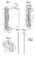
- FIG. 1 is a perspective view of an exemplary print head having a maintenance module embodying the principles of the present invention mounted thereto;
- FIG. 2 is front view of the maintenance module of FIG. 1;
- FIG. 3 is a right-hand side view of the maintenance module;
- FIG. 4 is a left-hand side view of the maintenance module;
- FIG. 5 is a top view of the maintenance module; and
- FIG. 6 is a partial view of the lower portion of the maintenance module as shown in the circled region of FIG. 1.
-
- While the present invention is susceptible of embodiment in various forms, there is shown in the drawings and will hereinafter be described a presently preferred embodiment with the understanding that the present disclosure is to be considered an exemplification of the invention and is not intended to limit the invention to the specific embodiment illustrated.
- Referring now to the figures and in particular to FIG. 1, there is shown a
maintenance module 10 mounted to an exemplaryfluid jet device 12, such as the illustrated print head. Although the present invention is presented with reference to a print head or inkjet device, those skilled in the art will recognize that thepresent maintenance module 10 can be used with anyfluid jet device 12, including inkjet print heads, adhesive jetting devices and the like, without limitation. As set forth above, theprint head 12 includes a plurality of actuators (not shown) that, upon actuation, eject or push a fluid therefrom. The fluid exits the device through a plurality of orifices on a front plate (not shown). - The
maintenance module 10 is mounted to the front of thefluid jet device 12. Themaintenance module 10 includes arear plate 14 referred to as a chamber plate/orifice plate. Therear plate 14 is an elongated member that defines a major axis (or longitudinal axis) 16 and a minor axis (or transverse axis) 18. Therear plate 14 includes a plurality of mountingholes 20 extending adjacent and parallel to each of theelongated edges 22a,b of theplate 14, parallel to themajor axis 16. - The mounting holes 20 are counter-bored or tapered, as indicated at 24, to permit mounting the
maintenance module 10 to thefluid jet device 12 so that the fasteners (not shown) that are used to mount themodule 10 are flush (or recessed) relative to themodule 10. - The
plate 14 includes a plurality oforifices 26 formed longitudinally along theplate 14 generally at a center thereof. In a present embodiment, two parallel rows oforifices 26a,b are formed in theplate 14 parallel to thelongitudinal axis 16. Theorifices 26a,b provide a flow path for fluid that is ejected from the actuators onto the substrate. - The
rear plate 14 includes avacuum opening 28 formed therein at about, and inwardly of one of the minor ortransverse edges 30. Thevacuum opening 28 is formed inwardly of theedge 30, between the major orlongitudinal edges 22a,b (essentially along the longitudinal axis 16). In a preferred embodiment, thevacuum opening 28 is formed having a chamfered or tapered edge, as indicated 32. That is, the angle formed between therear plate surface 34 and theopening 28 is less than 90 degrees (eliminating a sharp angle at the edge). - The
rear plate 14 further includes a rear or mountingflange 36. In a present embodiment, theflange 36 is formed as part of or integral with therear plate 14. In the present embodiment, therear plate 14 is formed from a rigid material, such as a metal to provide structural integrity and strength to themodule 10. Anotch 38 can be formed in therear plate 14, along one of themajor edges 22a. Thenotch 38 facilitates properly orienting themodule 10 on theprint head 12. In a current embodiment, thenotch 38 extends through a front portion of theplate 14, but does not extend into therear flange 36. - The
maintenance module 10 includes a maintenance plate orfront plate 40 mounted to therear plate 14. Themaintenance plate 40 includes a plurality offastener openings 42 extending inwardly of and parallel tolongitudinal edges 44a,b of theplate 40. The maintenanceplate fastener openings 42 correspond to the rearplate mounting openings 20. In that themaintenance plate 40 is a relatively thin member (presently about 0,25 mm thick), thefastener openings 42 are through-openings, rather than counter-bored. This also facilitates flush (or a low surface) mounting of the fasteners (not shown) that are used to mount themaintenance module 10 to thefluid jet head 12. Themaintenance plate 40 can include anotch 46 that corresponds to therear plate notch 38. Again, thisnotch 46 is used to assure properly orienting themodule 10 on theprint head 12. - An elongated
central channel 48 is formed in themaintenance plate 40. Thecentral charnel 48 is formed interior of (between) thefastener openings 42 and extends longitudinally along themaintenance plate 40 to fully expose the rear plate orifices 26. In a current embodiment, thechannel 48 is formed by a pair of generally parallel and spacededges 50a,b that, at one end (as indicated at 50c), are joined by asemi-circular edge 52 and at an opposing end (as indicated at 50d, overlying the vacuum opening 28), taper toward one another, terminating at an arcuatecentral region 50e. The arcuatecentral region 50e defines a funneling region that terminates over thevacuum opening 28 in therear plate 14. It has been found that the channel edge tapers (at 50d) facilitate directing fluid that is expelled from theorifices 26 but is not jetted on to a substrate. For example, it has been found that thechannel edges 50a,b, thetaper 50d and the funnelingregion 50e help to direct fluid (e.g., ink) to thevacuum opening 28 when ink drips from theorifices 26 or if ink is expelled from theorifices 26 during, for example, a purge or priming cycle. - Referring briefly to FIG. 6, the various tapers (in the
maintenance plate channel 50d,e and the chamber plate/orifice plate vacuum opening as at 32) will be described with reference to the x-axis oriented parallel to the rear plate transverse orminor axis 18, the y-axis oriented parallel to the rear plate longitudinal ormajor axis 16 and the z-axis oriented perpendicular to theplate 14, into the plane defined by the x- and y-axes. The maintenance plate channel edges as at 50d taper inwardly (toward one another) in the y-axis direction whereas the rear plate vacuum opening edges as at 32 taper inwardly in the z-axis direction. This multi-directional taper has been found to facilitate directing fluid that is in thechannel 48 toward and into thevacuum opening 28, rather than merely accumulating at the base of thechannel 48 in the tapered region (as at 50d). It has been observed that this greatly facilitates the removal or vacuuming away of any fluid that may drip down the front of the chamber plate/orifice plate 14 within themaintenance plate channel 48. - As set forth above, the
maintenance plate 40 is formed from a metal, preferably, a stainless steel. However, theplate 40 is a relatively thin element. To this end, themaintenance plate 40 is preferably bonded to therear plate 14 by, for example, an adhesive. The adhesive should be applied so as to prevent exposure of the adhesive within or near any of theorifices 26. It has also been found that a coating (as indicated at 54) can be applied to the outer surface of themaintenance plate 40. For example, acoating 54 of a fluoropolymer resin, such as TEFLON ® can be applied to themaintenance plate 40 to facilitate cleaning the plate, 40 and maintaining theplate 40 free of debris. - Although the present
fluid jet device 12 andmaintenance module 10 are shown in a vertical orientation (that is, with thelongitudinal axis 16 vertical), those skilled in the art will recognize that thepresent module 10 can be configured for mounting to a jet device that is oriented horizontally or at an angle between the vertical and the horizontal, without departing from the scope and spirit of the present invention.
Claims (15)
- A maintenance module for a fluid jet device (12), comprising :a first plate (14) defining a longitudinal axis (16) and a transverse axis (18) perpendicular to the longitudinal axis, the plate having a plurality of orifices (26) formed therein extending parallel to the longitudinal axis inwardly of longitudinal edges (22a, b) of the first plate (14), the first plate including a vacuum opening (28) formed therein at about a transverse edge (30) of the first plate, the vacuum opening formed perpendicular to a plane defined by the longitudinal and transverse axes; anda second plate (40) affixed to the first plate (14), the second plate defining a longitudinal axis and a transverse axis perpendicular to the longitudinal axis, the plate having an elongated channel (48) therein extending over the first plate orifices (26) so that the orifices are exposed through the elongated channel, the channel defined by opposing longitudinal edges (50a, b) extending parallel to the longitudinal axis, the channel having tapered edges (50 d) at about an end thereof converging to an arcuate funneling region (50 e), the second plate (40) overlying the first plate (14) such that the funneling region extends along an edge of the vacuum opening (28).
- The maintenance module in accordance with claim 1 wherein the plurality of orifices (26) formed in the first plate (14) are disposed in at least one row.
- The maintenance module in accordance with one of claims 1 or 2, wherein the vacuum opening (28) is formed on the longitudinal axis and wherein the channel (48) is formed symmetrically about the longitudinal axis.
- The maintenance module in accordance with one of claims 1 to 3, wherein the first plate (14) includes a plurality of mounting openings (20) formed therein, the mounting openings extending along opposing longitudinal edges (22a, b) of the plate, parallel to the longitudinal axis and outwardly spaced from the orifices.
- The maintenance module in accordance with claim 4, wherein the mounting openings (20) are counter-bored.
- The maintenance module in accordance with claim 4, wherein the second plate (40) includes a plurality of fastener openings (42) corresponding to and aligning over the first plate mounting openings (20).
- The maintenance module in accordance with one of claims 1 to 6, wherein the vacuum opening (28) is formed having inwardly tapered walls.
- The maintenance module in accordance with one of claims 1 to 7, including an orienting notch (46) formed in the second plate (40) and an orienting notch (38) formed partially through the first plate (14), the notches (46, 38) aligning with one another.
- The maintenance module in accordance with one of claims 1 to 8, wherein the first plate (14) includes a flange (36) extending about a periphery thereof.
- The maintenance module in accordance with one of claims 1 to 9, wherein the second plate (40) has a polymer coating (54) thereon.
- The maintenance module in accordance with one of claims 1 to 10, wherein the second plate (40) is bonded to the first plate(14).
- The maintenance module in accordance with claims 1 to 11, wherein the plurality of orifices (26) formed in the first plate are disposed in two parallel rows (26a, b).
- The maintenance module in accordance with one of claims 1 to 12, wherein said plurality of orifices (26) said first plate (14) ar formed inwardly of said longitudinal edges (22a ,b) centrally therof.
- The maintenance module in accordance with one of claims 1 to 13, wherein the vacuum opening (28) is longitudinally aligned with the plate orifices (26).
- A fluid jet device of the type having a fluid chamber (12), at least one actuator in fluid communication fluid chamber for providing a motive force for jetting the fluid therefrom, and at least one orifice for jetting fluid from the actuator, the fluid jetting device including a maintenance module according to one of claims 1 to 14, mounted thereto to overlie the at least one orifice.
Applications Claiming Priority (2)
| Application Number | Priority Date | Filing Date | Title |
|---|---|---|---|
| US71300 | 1987-07-09 | ||
| US10/071,300 US6637862B2 (en) | 2002-02-08 | 2002-02-08 | Maintenance module for fluid jet device |
Publications (3)
| Publication Number | Publication Date |
|---|---|
| EP1334833A2 true EP1334833A2 (en) | 2003-08-13 |
| EP1334833A3 EP1334833A3 (en) | 2003-10-01 |
| EP1334833B1 EP1334833B1 (en) | 2008-09-17 |
Family
ID=27610539
Family Applications (1)
| Application Number | Title | Priority Date | Filing Date |
|---|---|---|---|
| EP03290279A Expired - Lifetime EP1334833B1 (en) | 2002-02-08 | 2003-02-04 | Maintenance module for fluid jet device and said fluid jet device |
Country Status (8)
| Country | Link |
|---|---|
| US (2) | US6637862B2 (en) |
| EP (1) | EP1334833B1 (en) |
| JP (1) | JP4316895B2 (en) |
| AT (1) | ATE408506T1 (en) |
| AU (1) | AU2003200430B2 (en) |
| CA (1) | CA2415649C (en) |
| DE (1) | DE60323552D1 (en) |
| IL (1) | IL153735A (en) |
Cited By (2)
| Publication number | Priority date | Publication date | Assignee | Title |
|---|---|---|---|---|
| EP1706270A4 (en) * | 2003-12-30 | 2009-08-19 | Dimatix Inc | DROPLET EJECTION ASSEMBLY |
| US8287093B2 (en) | 2003-12-30 | 2012-10-16 | Fujifilm Dimatix, Inc. | Drop ejection assembly |
Families Citing this family (2)
| Publication number | Priority date | Publication date | Assignee | Title |
|---|---|---|---|---|
| US20050099451A1 (en) * | 2003-11-04 | 2005-05-12 | Videojet Technologies Inc. | Method and apparatus for reducing debris accumulation in an ink jet printhead |
| US8876252B2 (en) | 2011-05-02 | 2014-11-04 | Illinois Tool Works, Inc. | Solvent flushing for fluid jet device |
Citations (1)
| Publication number | Priority date | Publication date | Assignee | Title |
|---|---|---|---|---|
| US4418355A (en) | 1982-01-04 | 1983-11-29 | Exxon Research And Engineering Co. | Ink jet apparatus with preloaded diaphragm and method of making same |
Family Cites Families (24)
| Publication number | Priority date | Publication date | Assignee | Title |
|---|---|---|---|---|
| JPS5830830B2 (en) * | 1979-02-23 | 1983-07-01 | 株式会社リコー | Multi-nozzle head for inkjet |
| US4367479A (en) * | 1980-11-03 | 1983-01-04 | Exxon Research And Engineering Co. | Method and apparatus for purging and/or priming an ink jet |
| JPS5912857A (en) * | 1982-07-14 | 1984-01-23 | Canon Inc | Recording head |
| US4479136A (en) * | 1983-02-17 | 1984-10-23 | Exxon Research & Engineering Co. | Cleaning system and method for ink jet printer |
| US4528996A (en) * | 1983-12-22 | 1985-07-16 | The Mead Corporation | Orifice plate cleaning system |
| JPS61248750A (en) | 1985-04-26 | 1986-11-06 | Matsushita Electric Ind Co Ltd | Inkjet recording method |
| US4827287A (en) * | 1988-08-08 | 1989-05-02 | Eastman Kodak Company | Continuous ink jet printer having improved stimulation waveguide construction |
| US4970535A (en) * | 1988-09-26 | 1990-11-13 | Tektronix, Inc. | Ink jet print head face cleaner |
| JPH02108549A (en) | 1988-09-26 | 1990-04-20 | Tektronix Inc | Method and device for washing ink-jet-head |
| US5184147A (en) * | 1991-04-22 | 1993-02-02 | Tektronix, Inc. | Ink jet print head maintenance system |
| GB9603813D0 (en) | 1996-02-22 | 1996-04-24 | Videojet Systems Int | An ink jet printing system |
| JPH10138515A (en) | 1996-11-07 | 1998-05-26 | Canon Inc | Ink jet recording device |
| JP3417449B2 (en) | 1997-01-20 | 2003-06-16 | セイコーエプソン株式会社 | Ink jet recording device |
| GB2339170A (en) * | 1998-07-25 | 2000-01-19 | Markem Tech Ltd | Printhead with integral ink gutter |
| US6406123B1 (en) | 1998-09-07 | 2002-06-18 | Seiko Epson Corporation | Capping unit for ink jet recording head incorporated in ink jet recording apparatus and method of manufacturing the same |
| US6164752A (en) * | 1998-11-06 | 2000-12-26 | Xerox Corporation | Ink jet print head maintenance method |
| US6267464B1 (en) * | 1998-12-28 | 2001-07-31 | Eastman Kodak Company | Self cleaning ink jet printhead cartridges |
| US6283575B1 (en) * | 1999-05-10 | 2001-09-04 | Eastman Kodak Company | Ink printing head with gutter cleaning structure and method of assembling the printer |
| US6196657B1 (en) * | 1999-06-16 | 2001-03-06 | Eastman Kodak Company | Multi-fluidic cleaning for ink jet print heads |
| JP4199881B2 (en) * | 1999-07-02 | 2008-12-24 | セーレン株式会社 | Inkjet ejection head and inkjet recording apparatus |
| GB9917996D0 (en) | 1999-07-30 | 1999-09-29 | Xaar Technology Ltd | Droplet deposition method and apparatus |
| JP2001088326A (en) | 1999-09-27 | 2001-04-03 | Nec Niigata Ltd | Head cleaning device for ink-jet printer |
| ATE345934T1 (en) * | 2000-06-08 | 2006-12-15 | Illinois Tool Works | CLEANING A LIQUID JET DEVICE |
| US6406125B1 (en) * | 2000-06-08 | 2002-06-18 | Illinois Tool Works Inc. | System and method for maintaining the front of a fluid jet device in a relatively clean condition |
-
2002
- 2002-02-08 US US10/071,300 patent/US6637862B2/en not_active Expired - Lifetime
- 2002-12-29 IL IL15373502A patent/IL153735A/en not_active IP Right Cessation
-
2003
- 2003-01-07 CA CA002415649A patent/CA2415649C/en not_active Expired - Fee Related
- 2003-01-08 JP JP2003002206A patent/JP4316895B2/en not_active Expired - Fee Related
- 2003-02-04 DE DE60323552T patent/DE60323552D1/en not_active Expired - Lifetime
- 2003-02-04 AT AT03290279T patent/ATE408506T1/en not_active IP Right Cessation
- 2003-02-04 EP EP03290279A patent/EP1334833B1/en not_active Expired - Lifetime
- 2003-02-10 AU AU2003200430A patent/AU2003200430B2/en not_active Ceased
- 2003-05-02 US US10/428,575 patent/US6935721B2/en not_active Expired - Lifetime
Patent Citations (1)
| Publication number | Priority date | Publication date | Assignee | Title |
|---|---|---|---|---|
| US4418355A (en) | 1982-01-04 | 1983-11-29 | Exxon Research And Engineering Co. | Ink jet apparatus with preloaded diaphragm and method of making same |
Cited By (3)
| Publication number | Priority date | Publication date | Assignee | Title |
|---|---|---|---|---|
| EP1706270A4 (en) * | 2003-12-30 | 2009-08-19 | Dimatix Inc | DROPLET EJECTION ASSEMBLY |
| EP2415606A3 (en) * | 2003-12-30 | 2012-05-09 | Dimatix, Inc. | Drop ejection assembly |
| US8287093B2 (en) | 2003-12-30 | 2012-10-16 | Fujifilm Dimatix, Inc. | Drop ejection assembly |
Also Published As
| Publication number | Publication date |
|---|---|
| IL153735A0 (en) | 2003-07-06 |
| AU2003200430B2 (en) | 2004-01-15 |
| DE60323552D1 (en) | 2008-10-30 |
| AU2003200430A1 (en) | 2003-08-28 |
| ATE408506T1 (en) | 2008-10-15 |
| EP1334833A3 (en) | 2003-10-01 |
| EP1334833B1 (en) | 2008-09-17 |
| IL153735A (en) | 2005-11-20 |
| JP4316895B2 (en) | 2009-08-19 |
| JP2003237094A (en) | 2003-08-26 |
| US6637862B2 (en) | 2003-10-28 |
| US6935721B2 (en) | 2005-08-30 |
| CA2415649C (en) | 2006-10-03 |
| US20030151644A1 (en) | 2003-08-14 |
| CA2415649A1 (en) | 2003-08-08 |
| US20040017432A1 (en) | 2004-01-29 |
Similar Documents
| Publication | Publication Date | Title |
|---|---|---|
| EP0887190A2 (en) | Ink-jet recording device | |
| US6802588B2 (en) | Fluid jet apparatus and method for cleaning inkjet printheads | |
| JP3781284B2 (en) | Inkjet recording head and recording apparatus therefor | |
| US20010050697A1 (en) | System and method for maintaining the front of a fluid jet device in a relatively clean condition | |
| KR101331568B1 (en) | Flushing Unit | |
| JP2010532721A (en) | Integrated micromachined gutter for inkjet printheads | |
| WO2000043209A1 (en) | Print head having air suction | |
| US6270205B1 (en) | Ink-jet print head with ink supply channel | |
| CN102427949A (en) | Printhead With Porous Catcher | |
| US6513918B1 (en) | Screen mesh catcher for a continuous ink jet printer and method for making same | |
| JP2007529338A (en) | Cleaning system for continuous inkjet printer | |
| JPS62500511A (en) | Inkjet printing equipment with improved starting system | |
| JP2001088326A (en) | Head cleaning device for ink-jet printer | |
| EP1334833B1 (en) | Maintenance module for fluid jet device and said fluid jet device | |
| US6623113B2 (en) | Inkjet recording head including electrode assembly for deflecting ink droplets | |
| EP2255968B1 (en) | Droplet deposition apparatus | |
| US7004560B2 (en) | Cleaning device for cleaning inkjet head | |
| EP1162071B1 (en) | Cleaning a liquid jet device | |
| JPS60184851A (en) | Ink mist remover | |
| JP2007244973A (en) | Droplet ejecting apparatus and coating body manufacturing method | |
| CN101868352A (en) | Ink jet print head with automatic cleaning at start of printing | |
| US8727481B2 (en) | Printhead module | |
| JP4643294B2 (en) | Head maintenance device | |
| JPH01306257A (en) | Ink jet head | |
| JPS629427B2 (en) |
Legal Events
| Date | Code | Title | Description |
|---|---|---|---|
| PUAI | Public reference made under article 153(3) epc to a published international application that has entered the european phase |
Free format text: ORIGINAL CODE: 0009012 |
|
| AK | Designated contracting states |
Designated state(s): AT BE BG CH CY CZ DE DK EE ES FI FR GB GR HU IE IT LI LU MC NL PT SE SI SK TR |
|
| AX | Request for extension of the european patent |
Extension state: AL LT LV MK RO |
|
| PUAL | Search report despatched |
Free format text: ORIGINAL CODE: 0009013 |
|
| AK | Designated contracting states |
Kind code of ref document: A3 Designated state(s): AT BE BG CH CY CZ DE DK EE ES FI FR GB GR HU IE IT LI LU MC NL PT SE SI SK TR |
|
| AX | Request for extension of the european patent |
Extension state: AL LT LV MK RO |
|
| 17P | Request for examination filed |
Effective date: 20040323 |
|
| AKX | Designation fees paid |
Designated state(s): AT BE BG CH CY CZ DE DK EE ES FI FR GB GR HU IE IT LI LU MC NL PT SE SI SK TR |
|
| 17Q | First examination report despatched |
Effective date: 20060418 |
|
| GRAP | Despatch of communication of intention to grant a patent |
Free format text: ORIGINAL CODE: EPIDOSNIGR1 |
|
| GRAS | Grant fee paid |
Free format text: ORIGINAL CODE: EPIDOSNIGR3 |
|
| GRAA | (expected) grant |
Free format text: ORIGINAL CODE: 0009210 |
|
| AK | Designated contracting states |
Kind code of ref document: B1 Designated state(s): AT BE BG CH CY CZ DE DK EE ES FI FR GB GR HU IE IT LI LU MC NL PT SE SI SK TR |
|
| REG | Reference to a national code |
Ref country code: GB Ref legal event code: FG4D |
|
| REG | Reference to a national code |
Ref country code: CH Ref legal event code: EP |
|
| REG | Reference to a national code |
Ref country code: IE Ref legal event code: FG4D |
|
| REF | Corresponds to: |
Ref document number: 60323552 Country of ref document: DE Date of ref document: 20081030 Kind code of ref document: P |
|
| PG25 | Lapsed in a contracting state [announced via postgrant information from national office to epo] |
Ref country code: FI Free format text: LAPSE BECAUSE OF FAILURE TO SUBMIT A TRANSLATION OF THE DESCRIPTION OR TO PAY THE FEE WITHIN THE PRESCRIBED TIME-LIMIT Effective date: 20080917 Ref country code: AT Free format text: LAPSE BECAUSE OF FAILURE TO SUBMIT A TRANSLATION OF THE DESCRIPTION OR TO PAY THE FEE WITHIN THE PRESCRIBED TIME-LIMIT Effective date: 20080917 Ref country code: SI Free format text: LAPSE BECAUSE OF FAILURE TO SUBMIT A TRANSLATION OF THE DESCRIPTION OR TO PAY THE FEE WITHIN THE PRESCRIBED TIME-LIMIT Effective date: 20080917 |
|
| NLV1 | Nl: lapsed or annulled due to failure to fulfill the requirements of art. 29p and 29m of the patents act | ||
| PG25 | Lapsed in a contracting state [announced via postgrant information from national office to epo] |
Ref country code: BE Free format text: LAPSE BECAUSE OF FAILURE TO SUBMIT A TRANSLATION OF THE DESCRIPTION OR TO PAY THE FEE WITHIN THE PRESCRIBED TIME-LIMIT Effective date: 20080917 |
|
| PG25 | Lapsed in a contracting state [announced via postgrant information from national office to epo] |
Ref country code: BG Free format text: LAPSE BECAUSE OF FAILURE TO SUBMIT A TRANSLATION OF THE DESCRIPTION OR TO PAY THE FEE WITHIN THE PRESCRIBED TIME-LIMIT Effective date: 20081217 Ref country code: ES Free format text: LAPSE BECAUSE OF FAILURE TO SUBMIT A TRANSLATION OF THE DESCRIPTION OR TO PAY THE FEE WITHIN THE PRESCRIBED TIME-LIMIT Effective date: 20081228 |
|
| PG25 | Lapsed in a contracting state [announced via postgrant information from national office to epo] |
Ref country code: CZ Free format text: LAPSE BECAUSE OF FAILURE TO SUBMIT A TRANSLATION OF THE DESCRIPTION OR TO PAY THE FEE WITHIN THE PRESCRIBED TIME-LIMIT Effective date: 20080917 Ref country code: PT Free format text: LAPSE BECAUSE OF FAILURE TO SUBMIT A TRANSLATION OF THE DESCRIPTION OR TO PAY THE FEE WITHIN THE PRESCRIBED TIME-LIMIT Effective date: 20090217 Ref country code: NL Free format text: LAPSE BECAUSE OF FAILURE TO SUBMIT A TRANSLATION OF THE DESCRIPTION OR TO PAY THE FEE WITHIN THE PRESCRIBED TIME-LIMIT Effective date: 20080917 Ref country code: SK Free format text: LAPSE BECAUSE OF FAILURE TO SUBMIT A TRANSLATION OF THE DESCRIPTION OR TO PAY THE FEE WITHIN THE PRESCRIBED TIME-LIMIT Effective date: 20080917 |
|
| PLBE | No opposition filed within time limit |
Free format text: ORIGINAL CODE: 0009261 |
|
| STAA | Information on the status of an ep patent application or granted ep patent |
Free format text: STATUS: NO OPPOSITION FILED WITHIN TIME LIMIT |
|
| PG25 | Lapsed in a contracting state [announced via postgrant information from national office to epo] |
Ref country code: DK Free format text: LAPSE BECAUSE OF FAILURE TO SUBMIT A TRANSLATION OF THE DESCRIPTION OR TO PAY THE FEE WITHIN THE PRESCRIBED TIME-LIMIT Effective date: 20080917 Ref country code: EE Free format text: LAPSE BECAUSE OF FAILURE TO SUBMIT A TRANSLATION OF THE DESCRIPTION OR TO PAY THE FEE WITHIN THE PRESCRIBED TIME-LIMIT Effective date: 20080917 |
|
| 26N | No opposition filed |
Effective date: 20090618 |
|
| PG25 | Lapsed in a contracting state [announced via postgrant information from national office to epo] |
Ref country code: MC Free format text: LAPSE BECAUSE OF NON-PAYMENT OF DUE FEES Effective date: 20090228 |
|
| REG | Reference to a national code |
Ref country code: CH Ref legal event code: PL |
|
| PG25 | Lapsed in a contracting state [announced via postgrant information from national office to epo] |
Ref country code: CH Free format text: LAPSE BECAUSE OF NON-PAYMENT OF DUE FEES Effective date: 20090228 Ref country code: LI Free format text: LAPSE BECAUSE OF NON-PAYMENT OF DUE FEES Effective date: 20090228 |
|
| PG25 | Lapsed in a contracting state [announced via postgrant information from national office to epo] |
Ref country code: IE Free format text: LAPSE BECAUSE OF NON-PAYMENT OF DUE FEES Effective date: 20090204 Ref country code: SE Free format text: LAPSE BECAUSE OF FAILURE TO SUBMIT A TRANSLATION OF THE DESCRIPTION OR TO PAY THE FEE WITHIN THE PRESCRIBED TIME-LIMIT Effective date: 20081217 |
|
| PG25 | Lapsed in a contracting state [announced via postgrant information from national office to epo] |
Ref country code: GR Free format text: LAPSE BECAUSE OF FAILURE TO SUBMIT A TRANSLATION OF THE DESCRIPTION OR TO PAY THE FEE WITHIN THE PRESCRIBED TIME-LIMIT Effective date: 20081218 |
|
| PG25 | Lapsed in a contracting state [announced via postgrant information from national office to epo] |
Ref country code: LU Free format text: LAPSE BECAUSE OF NON-PAYMENT OF DUE FEES Effective date: 20090204 |
|
| PG25 | Lapsed in a contracting state [announced via postgrant information from national office to epo] |
Ref country code: HU Free format text: LAPSE BECAUSE OF FAILURE TO SUBMIT A TRANSLATION OF THE DESCRIPTION OR TO PAY THE FEE WITHIN THE PRESCRIBED TIME-LIMIT Effective date: 20090318 |
|
| PG25 | Lapsed in a contracting state [announced via postgrant information from national office to epo] |
Ref country code: TR Free format text: LAPSE BECAUSE OF FAILURE TO SUBMIT A TRANSLATION OF THE DESCRIPTION OR TO PAY THE FEE WITHIN THE PRESCRIBED TIME-LIMIT Effective date: 20080917 |
|
| PG25 | Lapsed in a contracting state [announced via postgrant information from national office to epo] |
Ref country code: CY Free format text: LAPSE BECAUSE OF FAILURE TO SUBMIT A TRANSLATION OF THE DESCRIPTION OR TO PAY THE FEE WITHIN THE PRESCRIBED TIME-LIMIT Effective date: 20080917 |
|
| REG | Reference to a national code |
Ref country code: FR Ref legal event code: PLFP Year of fee payment: 14 |
|
| REG | Reference to a national code |
Ref country code: FR Ref legal event code: PLFP Year of fee payment: 15 |
|
| REG | Reference to a national code |
Ref country code: FR Ref legal event code: PLFP Year of fee payment: 16 |
|
| PGFP | Annual fee paid to national office [announced via postgrant information from national office to epo] |
Ref country code: GB Payment date: 20220225 Year of fee payment: 20 Ref country code: DE Payment date: 20220225 Year of fee payment: 20 |
|
| PGFP | Annual fee paid to national office [announced via postgrant information from national office to epo] |
Ref country code: IT Payment date: 20220222 Year of fee payment: 20 Ref country code: FR Payment date: 20220223 Year of fee payment: 20 |
|
| REG | Reference to a national code |
Ref country code: DE Ref legal event code: R071 Ref document number: 60323552 Country of ref document: DE |
|
| REG | Reference to a national code |
Ref country code: GB Ref legal event code: PE20 Expiry date: 20230203 |
|
| PG25 | Lapsed in a contracting state [announced via postgrant information from national office to epo] |
Ref country code: GB Free format text: LAPSE BECAUSE OF EXPIRATION OF PROTECTION Effective date: 20230203 |