EP1334552B1 - Method and apparatus for encoderless operation of a permanent magnet synchronous motor in an elevator - Google Patents
Method and apparatus for encoderless operation of a permanent magnet synchronous motor in an elevator Download PDFInfo
- Publication number
- EP1334552B1 EP1334552B1 EP01991993A EP01991993A EP1334552B1 EP 1334552 B1 EP1334552 B1 EP 1334552B1 EP 01991993 A EP01991993 A EP 01991993A EP 01991993 A EP01991993 A EP 01991993A EP 1334552 B1 EP1334552 B1 EP 1334552B1
- Authority
- EP
- European Patent Office
- Prior art keywords
- signal
- current feedback
- feedback loop
- current
- axis current
- Prior art date
- Legal status (The legal status is an assumption and is not a legal conclusion. Google has not performed a legal analysis and makes no representation as to the accuracy of the status listed.)
- Expired - Lifetime
Links
- 238000000034 method Methods 0.000 title claims description 26
- 230000001360 synchronised effect Effects 0.000 title claims description 24
- 230000009466 transformation Effects 0.000 claims description 9
- 230000004044 response Effects 0.000 claims description 5
- 238000001914 filtration Methods 0.000 claims description 4
- 230000008569 process Effects 0.000 claims description 3
- 230000001131 transforming effect Effects 0.000 claims 10
- 238000002347 injection Methods 0.000 description 13
- 239000007924 injection Substances 0.000 description 13
- 230000008859 change Effects 0.000 description 3
- 230000000694 effects Effects 0.000 description 3
- 239000011159 matrix material Substances 0.000 description 3
- 230000004048 modification Effects 0.000 description 3
- 238000012986 modification Methods 0.000 description 3
- XEEYBQQBJWHFJM-UHFFFAOYSA-N Iron Chemical compound [Fe] XEEYBQQBJWHFJM-UHFFFAOYSA-N 0.000 description 2
- 230000003750 conditioning effect Effects 0.000 description 2
- 239000004020 conductor Substances 0.000 description 2
- 230000007423 decrease Effects 0.000 description 2
- 238000013461 design Methods 0.000 description 2
- 238000001514 detection method Methods 0.000 description 2
- 238000004804 winding Methods 0.000 description 2
- 230000005534 acoustic noise Effects 0.000 description 1
- 238000013459 approach Methods 0.000 description 1
- 238000004364 calculation method Methods 0.000 description 1
- 238000006243 chemical reaction Methods 0.000 description 1
- 239000012141 concentrate Substances 0.000 description 1
- 230000001143 conditioned effect Effects 0.000 description 1
- 230000001934 delay Effects 0.000 description 1
- 230000004069 differentiation Effects 0.000 description 1
- 230000005672 electromagnetic field Effects 0.000 description 1
- 230000005284 excitation Effects 0.000 description 1
- 238000002474 experimental method Methods 0.000 description 1
- 230000004907 flux Effects 0.000 description 1
- 230000014509 gene expression Effects 0.000 description 1
- 230000006698 induction Effects 0.000 description 1
- 229910052742 iron Inorganic materials 0.000 description 1
- 238000004519 manufacturing process Methods 0.000 description 1
- 238000013178 mathematical model Methods 0.000 description 1
- 238000012544 monitoring process Methods 0.000 description 1
- 230000009467 reduction Effects 0.000 description 1
- 230000003595 spectral effect Effects 0.000 description 1
- 238000001228 spectrum Methods 0.000 description 1
Images


Classifications
-
- H—ELECTRICITY
- H02—GENERATION; CONVERSION OR DISTRIBUTION OF ELECTRIC POWER
- H02P—CONTROL OR REGULATION OF ELECTRIC MOTORS, ELECTRIC GENERATORS OR DYNAMO-ELECTRIC CONVERTERS; CONTROLLING TRANSFORMERS, REACTORS OR CHOKE COILS
- H02P21/00—Arrangements or methods for the control of electric machines by vector control, e.g. by control of field orientation
-
- H—ELECTRICITY
- H02—GENERATION; CONVERSION OR DISTRIBUTION OF ELECTRIC POWER
- H02P—CONTROL OR REGULATION OF ELECTRIC MOTORS, ELECTRIC GENERATORS OR DYNAMO-ELECTRIC CONVERTERS; CONTROLLING TRANSFORMERS, REACTORS OR CHOKE COILS
- H02P21/00—Arrangements or methods for the control of electric machines by vector control, e.g. by control of field orientation
- H02P21/14—Estimation or adaptation of machine parameters, e.g. flux, current or voltage
- H02P21/18—Estimation of position or speed
-
- B—PERFORMING OPERATIONS; TRANSPORTING
- B66—HOISTING; LIFTING; HAULING
- B66B—ELEVATORS; ESCALATORS OR MOVING WALKWAYS
- B66B1/00—Control systems of elevators in general
- B66B1/34—Details, e.g. call counting devices, data transmission from car to control system, devices giving information to the control system
- B66B1/3492—Position or motion detectors or driving means for the detector
-
- H—ELECTRICITY
- H02—GENERATION; CONVERSION OR DISTRIBUTION OF ELECTRIC POWER
- H02P—CONTROL OR REGULATION OF ELECTRIC MOTORS, ELECTRIC GENERATORS OR DYNAMO-ELECTRIC CONVERTERS; CONTROLLING TRANSFORMERS, REACTORS OR CHOKE COILS
- H02P2203/00—Indexing scheme relating to controlling arrangements characterised by the means for detecting the position of the rotor
- H02P2203/11—Determination or estimation of the rotor position or other motor parameters based on the analysis of high-frequency signals
-
- H—ELECTRICITY
- H02—GENERATION; CONVERSION OR DISTRIBUTION OF ELECTRIC POWER
- H02P—CONTROL OR REGULATION OF ELECTRIC MOTORS, ELECTRIC GENERATORS OR DYNAMO-ELECTRIC CONVERTERS; CONTROLLING TRANSFORMERS, REACTORS OR CHOKE COILS
- H02P2207/00—Indexing scheme relating to controlling arrangements characterised by the type of motor
- H02P2207/05—Synchronous machines, e.g. with permanent magnets or DC excitation
Definitions
- This invention pertains to the field of sensing a position of an elevator motor, and in particular, to sensing the position of the motor without using an encoder.
- a synchronous AC motor can achieve a desired torque production only if the applied stator waveforms, typically voltages, have phase which is coordinated with the rotor position. A knowledge of the rotor position is thus essential for smooth operation of an elevator drive.
- the present invention uses characteristics of a permanent magnet synchronous motor (PMSM) to determine the position of the motor.
- PMSM permanent magnet synchronous motor
- An electric motor relies on two basic principles of electromagnetism. First, whenever electric current is passed through a wire, an electromagnetic field is created around the wire with a strength proportional the amount of current, and second, whenever wire is moved through a magnetic field, electric current is generated in the wire which depends on the strength of the magnetic field, the size of the wire, and the speed and distance at which the wire moves through the magnetic field.
- a PMSM motor is an AC motor that includes a stationary section called the stator, and a rotating section called the rotor. Wire windings and north-south magnetic poles in the stator are arranged so that an AC current introduced into the windings causes a magnetic field that rotates around the stator. This rotating magnetic field then induces a current in the rotor. The induced rotor current produces a magnetic field that chases the rotating stator field, thus causing the rotor, which is attached to a shaft, to turn. The speed of rotation of the magnetic field is called the synchronous speed of the motor.
- the rotor electromagnet tries to catch the rotating stator magnetic field, but as it approaches alignment with the stator, the rotating magnetic field no longer intersects the rotor conductors, so the induced current decreases and the rotor field decreases.
- the rotor then slows down and "slips" below the speed of the stator's rotating magnetic field. As the rotor slows, more conductors are intersected by the rotating magnetic field, causing the rotor current and field to increase again, resuming the chase of the stator field.
- the synchronous motor in a steady state tends to run at a nearly constant speed depending on the frequency of the applied AC voltage.
- the AC motor torque is a function of the amplitude and phase of the applied AC voltage.
- U.S. Patent No. 5,903,128 (Sakakibara et al.) entitled "Sensorless Control System and Method of Permanent Magnet Synchronous Motor” discloses modifying the supply voltage so that the position can be inferred from the system response. The modification, however, is quite simple (one or two pulses), so it is likely to result in limited performance.
- a permanent magnet synchronous motor is controlled using d-axis current and q-axis current along with respective d-current and q-current feedback loops.
- the speed and position of the motor are determined by injecting a first signal into the d-axis current and observing the response in the q-current feedback loop.
- Part of the q-current feedback signal is demodulated with a second signal which is 90 degrees out of phase from the first signal.
- the demodulated signal is preferably sent through a low pass filter before being received by an observer controller.
- the observer controller outputs a position estimate which is used to modify the d-current feedback signal and a speed estimate which is used to modify the q-axis current.
- an apparatus for determining speed and position of a permanent magnet synchronous motor includes d-axis current means for providing d-axis current to the motor; the d-axis current means including a d-current feedback loop; q-axis current means for providing q-axis current to the motor; the q-axis current means including a q-current feedback loop; means for injecting a first signal into the d-axis current means; position estimating means for measuring current feedback responsive to the injected first signal to determine an estimated position of the motor; and speed estimating means for measuring current feedback responsive to the injected first signal to determine an estimated speed of the motor.
- a method for determining speed and position of a permanent magnet synchronous motor includes the steps of (a) providing d-axis current to the motor, including providing a d-current feedback loop; (b) providing q-axis current to the motor, including providing a q-current feedback loop; (c) injecting a first signal into the d-axis current outside of the d-current feedback loop; (d) measuring current feedback responsive to the injected first signal to determine an estimated position of the motor; and (f) measuring current feedback responsive to the injected first signal to determine an estimated speed of the motor.
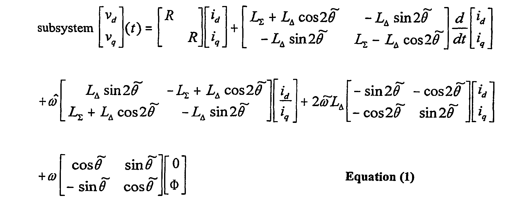
- Equation 1 we could find the unknown quantities (position and electrical parameters) from Equation 1 using standard estimation reasoning: measure the electrical quantities (voltages and currents), process the signals to obtain a good approximation for the derivative (say by using state filters or other band-limited differentiation), and estimate the unknown parameters (say using the least squares method).
- the main issue is that we need the persistency of excitation, i.e., the signals should vary (in normal operation) enough to enable the estimation. This condition, however, is typically not satisfied in practice, and we are interested in modification in voltages and currents that enable estimation, while maintaining energy-efficient operation.
- the problem at hand is one of input design, i.e, what should we select for v d ( t ) and ⁇ q ( t ) so that the position and electrical parameters R, L ⁇ , L ⁇ can be reliably estimated from the presented equations. This "injection" should not affect the energy conversion, which occurs at low (DC) frequencies.
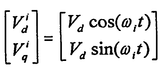
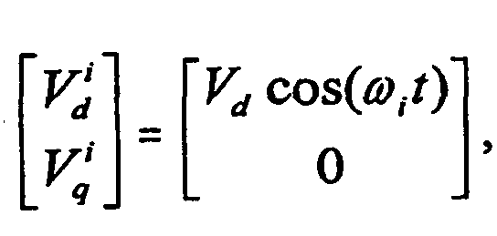
- An embodiment of the present invention superimposes a voltage signal in the form of onto the existing motor control commands.
- the injected frequency ⁇ i is of the order 800-850 Hz.
- the last term of Equation (1), the back-emf term has negligible value at the injected frequency ⁇ i . From Equation (1), the currents at the injected frequency satisfy the following equation: where the entries of the matrix are as follows:
- the position error can now be derived from the L 21 term.
- Calculation of the imaginary component of L 21 enables minimization of the effects of speed dependence at the high-speed operating region.
- the resistance actually has an important effect in adding phase to denominator, possibly making the estimation challenging.
- the injected frequency can be selected so that the terms involving ⁇ i dominate in all expressions.
- typical delays can be calculated for expected operating points and later compensated for. In our experiments we used the injected frequency high enough ( ⁇ i l ⁇ rated ⁇ 20) to improve on the signal-to-noise ratio.
- the input is amplified by an amplifier 12 and separately passed through an integrator 14 and an amplifier 16.
- the outputs of amplifier 12 and integrator 14 are combined at 18.
- the output of 18 is passed through an integrator 20 and combined at 22 with the output of amplifier 16 before passing through an integrator 24.
- the output of integrator 24 is the position estimate ⁇ and while the frequency estimate ⁇ and is taken from the output of integrator 20.
- the observer replaces the encoder in the prior art.
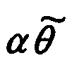
- the observer changes the position estimate ⁇ and such that the position error signal at its input is driven to zero, i.e., the estimated rotor position is driven close to the actual rotor position.
- the observer estimates (observes) the position and velocity of the motor shaft and the amount of torque mismatch between the demand of the elevator motion and the one supplied by the power electronics. This observer as it stands different from other observers designed for the same purpose.
- K p , K I , and ⁇ are made such that the characteristic polynomial s 3 + ⁇ s 2 + K p s + K i satisfies the dynamical requirements.
- K p is the proportional constant of the system and K I is the integral constant of the system. In our case, using the pole placement method, we choose all poles to be placed at 20 rad/sec.
- Information needed for initialization of the sensorless control algorithm initially is obtained from a separate initial position detection algorithm, such as, for example, one of the algorithms disclosed in U.S. Patent No. 5,608,300 (Kawabata et al.) or U.S. Patent No. 5,952,810 (Yamada et al.), that is executed before every lifting of the elevator brake.
- a control circuit 30 for an embodiment of the encoderless drive of the present invention is shown.
- a permanent magnet synchronous motor 32 is controlled by an output of a PWM (pulse width modulation) inverter 34.
- Motor 32 outputs an actual position ⁇ and an actual speed ⁇ .
- Current sensors 36, 38, 40 sense the output of PWM inverter 24, and their output is converted, typically by software, in a 3/2 transform block 42 where the measured signals are converted from 3-phase to 2-phase in a stationary frame.
- the 2-phase signals are multiplied by the synchronous transform matrix in stationary to synchronous frame transformation block 44.
- the output ⁇ and from observer controller 10 is input into the transform matrix.
- the d-current feedback Î d from block 44 is subtracted from the reference d-current I d / ref at a summing junction 46, with the result passing through a d-axis current regulator 58 and a notch filter 60 that rejects ⁇ i .
- the output of notch filter 60 is injected with an injection voltage V d cos( ⁇ i t ) at a summing junction 62 before going to a synchronous to stationary frame transformation block 64, where the signal is transformed so it is understandable to PWM converter 34.
- the frequency estimate ⁇ and from observer controller 10 is subtracted from a reference frequency ⁇ ref at a summing junction 50.
- the output is sent to a proportional integral controller 52.
- the q-current feedback Î q from block 44 is subtracted from the output of proportional integral controller 52 at a summing junction 48 before entering a q-axis current regulator 54.
- the output of regulator 54 is passed through a notch filter 56 which rejects ⁇ i .
- the output of notch filter 56 goes to stationary frame transformation block 64, where the signal is transformed so it is understandable to PWM converter 34.
- the signal from low pass filter 68 is the input to observer 10.
- the velocity estimate obtained using the present invention is compared with the reference velocity that we want to track.
- the velocity estimate obtained using the present invention is almost identical to the velocity estimate using an encoder.
- Additional embodiments include (1) time-varying ⁇ i , possibly with a random component for acoustic noise reduction, (2) injection at more than one frequency ⁇ i to improve the conditioning of the estimation problem, and (3) injection in both axes (i.e., V i / q ⁇ 0 ) to improve the conditioning of the estimation problem. Note that we are using steady-state relationships to model the electrical subsystem, so the injection frequency ⁇ i has to be maintained near a fixed value for several cycles (say 10) of ⁇ i .
- the purpose of injecting a signal is to spread the frequency spectrum of the injected signal such that it is not a pure tone but rather like noise so it is less disturbing to customers and/or users.
- a time varying signal such as ⁇ io + sin( ⁇ t ) optionally replaces all instances of ⁇ i in Fig. 2.
- the first dc term of the frequency is constant while the sinusoidal part is a slowly varying signal. This has the effect of causing the injected signal to be heard as noise rather than a tone.
- two frequencies V d 1 cos( ⁇ i 1 t ) + V d 2 cos( ⁇ i 2 t ), are optionally injected at summing junction 62. This necessitates a change in the feedback loop, where demodulation signals sin( ⁇ i 1 t ) and sin( ⁇ i 2 t ) are separately combined with the q-current feedback Î q at 72 and 74, respectively, before passing through low pass filter 68. Additional frequencies would be injected in similar fashion.
- L 11 , L 12 , L 21 , and L 22 are described in Equation (3).
- L 12 , L 21 enable generation of an error signal necessary for driving controller observer 10 while L 11 and L 22 enable determination of the d-axis and q-axis inductances.
- These (L 11 and L 22 ) inductances can also be used for the design of the current regulators and for determination of the quality of the estimate through the sensor-less operation.
- an additional injection voltage V q sin( ⁇ iq t ) is injected into the q-axis at a summing junction 76.
- the two injection frequencies could be the same or different.
- Fig. 5B The necessary change in the feedback loop is shown in Fig. 5B. Both of the axis currents, I d and I q , are processed. Demodulation signals sin( ⁇ id t ), cos( ⁇ iq t ) are combined with the q-current feedback Î q at 78 and the d-current feedback Î d at 80, respectively, before being added at a summing junction 86 before passing through low pass filter 68.
- demodulation signals sin( ⁇ id t ), cos( ⁇ iq t ) are optionally combined with the q-current feedback Î q at 82 and the d-current feedback Î d at 84, respectively, before being subtracted at a summing junction 88 for use in determining L ⁇ in block 90.
- Determining L ⁇ provides information regarding whether the method of the present invention is still reliable to use. This is preferable because as the motor is loaded, the rotor iron saturates and L ⁇ gets closer to zero, which is not good for the quality of the estimation. Monitoring L ⁇ thus determines the extent to which the method of the present invention can be used reliably.
- filtering of the injected filter occurs in notch filters 56, 60 and not in the feedback loop. This is an important difference in the case of command signals with some spectral content near the injected frequency. Such a signal component, which potentially degrades the estimation process, is eliminated by the notch filters.
Landscapes
- Engineering & Computer Science (AREA)
- Power Engineering (AREA)
- Automation & Control Theory (AREA)
- Computer Networks & Wireless Communication (AREA)
- Control Of Motors That Do Not Use Commutators (AREA)
- Control Of Ac Motors In General (AREA)
- Control Of Electric Motors In General (AREA)
Description








Claims (24)
- Apparatus for determining speed and position of a permanent magnet synchronous motor, comprising:d-axis current means for providing d-axis current to said motor;said d-axis current means including a d-current feedback loop;q-axis current means for providing q-axis current to said motor;said q-axis current means including a q-current feedback loop;means for injecting a first signal into said d-axis current means; andan observer controller including a third order position estimating means for measuring current feedback responsive to said injected first signal to determine an estimated position of said motor and speed estimating means for measuring current feedback responsive to said injected first signal to determine an estimated speed of said motor.
- Apparatus according to claim 1, further comprising:sensing means for sensing currents in 3-phase control signals controlling said motor;first transformation means for transforming said sensed currents to 2-phase stationary frame signals; andsecond transformation means for transforming said stationary frame signals to synchronous frame signals said observer controller receiving input from said q-current feedback loop and providing a position estimate to second transformation means.
- Apparatus according to claim 1, wherein said observer controller receives input from said q-current feedback loop and providing a speed estimate to said q-axis current means.
- Apparatus according to claim 3, further comprising:sensing means for sensing currents in 3-phase control signals controlling said motor;first transformation means for transforming said sensed currents to 2-phase stationary frame signals;second transformation means for transforming said stationary frame signals to synchronous frame signals; andsaid observer controller providing a position estimate to second transformation means.
- Apparatus according to claim 4, further comprising first demodulation means wherein said input to said observer controller from said q-current feedback loop is demodulated with a second signal before entering said observer controller, said second signal being 90 degrees out of phase with said first signal.
- Apparatus according to claim 5, wherein said demodulated input to said observer controller from said q-current feedback loop is passed through a low pass filter before entering said observer controller.
- Apparatus according to claim 5, wherein said d-axis current means includes a first notch filter at a frequency of said first signal and said q-axis current means includes a second notch filter at said frequency of said first signal, wherein said first notch filter is positioned exclusive of said d-current feedback loop and said second notch filter is positioned exclusive of said q-current feedback loop.
- Apparatus according to claim 5, wherein said first signal has a time-varying frequency.
- Apparatus according to claim 5, further comprising:means for injecting a third signal into said d-axis current means;second demodulation means for demodulating said q-current feedback loop with a fourth signal; andsumming means for summing outputs from said first and second demodulation means and sending an output of said summing means to said observer controller.
- Apparatus according to claim 5, further comprising:means for injecting a third signal into said q-axis current means;second demodulation means for demodulating said d-current feedback loop with a fourth signal; andsumming means for summing outputs from said first and second demodulation means and sending an output of said summing means to said observer controller.
- Apparatus according to claim 10, further comprising:third demodulation means for demodulating said q-current feedback loop with said fourth signal;fourth demodulation means for demodulating said d-current feedback loop with said second signal;second summing means for subtracting an output of said fourth demodulation means from an output of said third demodulation means; andmeans, responsive to an output from said second summing means, for determining a value for a differential inductance of said d-axis current means and said q-axis current means.
- Apparatus according to claim 4, wherein
said observer controller receives said input and processes said input in first, second, and third branches;
a first portion of said first branch amplifies said input signal by a first constant;
said second branch integrates said input signal using a second constant;
an output of said second branch and an output of said first portion are combined into a first combined signal in a second portion of said first branch;
said first combined signal is integrated to produce an integrated first combined signal, wherein said speed estimate is taken from said integrated first combined signal;
said third branch amplifies said input signal by a third constant;
an output of said third branch and said integrated first combined signal are combined in a third portion of said first branch to produce a second combined signal; and
said second combined signal is integrated to produce said position estimate. - A method for determining speed and position of a permanent magnet synchronous motor, comprising the steps of:providing d-axis current to said motor, including providing a d-current feedback loop;providing q-axis current to said motor, including providing a q-current feedback loop;injecting a first signal into said d-axis current outside of said d-current feedback loop;measuring current feedback responsive to said injected first signal;estimating a position of said motor using a third order observer in response to said current feedback to determine an estimated position of said motor; anddetermining an estimated speed of said motor in response to said current feedback.
- Method according to claim 13, further comprising the steps of:sensing currents in 3-phase control signals controlling said motor;transforming said sensed currents to 2-phase stationary frame signals;transforming said stationary frame signals to synchronous frame signals; andreceiving input from said q-current feedback loop and providing a position estimate for use in the step of transforming said stationary frame signals to synchronous frame signals.
- Method according to claim 13, further comprising the steps of:receiving input from said q-current feedback loop;providing a speed estimate based on said input from said q-current feedback loop;combining said speed estimate with a reference frequency to be used in the step of providing q-axis current.
- Method according to claim 15; further comprising the steps of:sensing currents in 3-phase control signals controlling said motor;transforming said sensed currents to 2-phase stationary frame signals;transforming said stationary frame signals to synchronous frame signals; andproviding a position estimate, based on input from said q-current feedback loop, to be used in the step of transforming said stationary frame signals to synchronous frame signals.
- Method according to claim 16, further comprising the step of demodulating q-current feedback with a second signal before using said input from said q-cucrent feedback loop to determine said speed estimate and said position estimate, said second signal being 90 degrees out of phase with said first signal.
- Method according to claim 17, further comprising the step of passing said demodulated q-current feedback through a low pass filter before using said input from said q-current feedback loop to determine said speed estimate and said position estimate.
- Method according to claim 17, wherein said step of providing d-axis current includes the step of filtering out a frequency of said first signal and said step of providing q-axis current includes filtering out said frequency of said first signal, wherein said steps of filtering out said frequency of said first signal are performed exclusive of said d-current feedback loop and said q-current feedback loop.
- Method according to claim 17, wherein said first signal has a time-varying frequency.
- Method according to claim 17, further comprising the steps of:injecting a third signal into said d-axis current;demodulating said q-current feedback loop with a fourth signal; andsumming outputs from the steps of demodulating with said second and fourth signals; andsending an output of said step of summing to said observer controller.
- Method according to claim 17, further comprising the steps of:injecting a third signal into said q-axis current;demodulating said d-current feedback loop with a fourth signal;summing outputs from the steps of demodulating with said second and fourth signals; andsending an output of said step of summing to said observer controller.
- Method according to claim 22, further comprising:demodulating said q-current feedback loop with said fourth signal;demodulating said d-current feedback loop with said second signal;subtracting an output of the step of demodulating with said second signal from an output of the step of demodulating with said fourth signal; anddetermining, based on the previous step, a value for a differential inductance of said d-axis current and said q-axis current.
- Method according to claim 17, wherein said steps of providing said speed estimate and said position estimates include:receiving said input and processing said input in first, second, and third branches;amplifying said input signal by a first constant in a first portion of said first branch;integrating said input signal in said second branch using a second constant;combining an output of said second branch and an output of said first portion into a first combined signal in a second portion of said first branch;integrating said first combined signal to produce an integrated first combined signal, wherein said speed estimate is taken from said integrated first combined signal;amplifying said input signal by a third constant in said third branch;combining an output of said third branch and said integrated first combined signal in a third portion of said first branch to produce a second combined signal; andintegrating said second combined signal to produce said position estimate.
Applications Claiming Priority (3)
| Application Number | Priority Date | Filing Date | Title |
|---|---|---|---|
| US709833 | 2000-11-10 | ||
| US09/709,833 US6492788B1 (en) | 2000-11-10 | 2000-11-10 | Method and apparatus for encoderless operation of a permanent magnet synchronous motor in an elevator |
| PCT/US2001/045844 WO2002039575A2 (en) | 2000-11-10 | 2001-10-18 | Method and apparatus for encoderless operation of a permanent magnet synchronous motor in an elevator |
Publications (2)
| Publication Number | Publication Date |
|---|---|
| EP1334552A2 EP1334552A2 (en) | 2003-08-13 |
| EP1334552B1 true EP1334552B1 (en) | 2005-09-28 |
Family
ID=24851469
Family Applications (1)
| Application Number | Title | Priority Date | Filing Date |
|---|---|---|---|
| EP01991993A Expired - Lifetime EP1334552B1 (en) | 2000-11-10 | 2001-10-18 | Method and apparatus for encoderless operation of a permanent magnet synchronous motor in an elevator |
Country Status (10)
| Country | Link |
|---|---|
| US (1) | US6492788B1 (en) |
| EP (1) | EP1334552B1 (en) |
| JP (1) | JP4027227B2 (en) |
| KR (1) | KR100763049B1 (en) |
| CN (1) | CN100397772C (en) |
| BR (1) | BR0115229A (en) |
| DE (1) | DE60113712T2 (en) |
| ES (1) | ES2250510T3 (en) |
| TW (1) | TW543278B (en) |
| WO (1) | WO2002039575A2 (en) |
Cited By (2)
| Publication number | Priority date | Publication date | Assignee | Title |
|---|---|---|---|---|
| EP3651346A1 (en) | 2018-11-07 | 2020-05-13 | ABB Schweiz AG | Method of controlling an electrical machine |
| EP3683955A1 (en) | 2019-01-18 | 2020-07-22 | ABB Schweiz AG | Method of controlling an electrical machine |
Families Citing this family (51)
| Publication number | Priority date | Publication date | Assignee | Title |
|---|---|---|---|---|
| US8217605B2 (en) * | 2000-11-10 | 2012-07-10 | Freescale Semiconductor, Inc. | Motor controller for determining a position of a rotor of an AC motor, AC motor system, and method of determining a position of a rotor of an AC motor |
| US7164590B2 (en) * | 2002-07-29 | 2007-01-16 | International Rectifier Corporation | Power transfer system with reduced component ratings |
| US6856109B2 (en) * | 2002-10-15 | 2005-02-15 | International Rectifier Corporation | Efficiency optimization control for permanent magnet motor drive |
| US6979967B2 (en) * | 2002-10-15 | 2005-12-27 | International Rectifier Corporation | Efficiency optimization control for permanent magnet motor drive |
| US6998811B2 (en) * | 2003-02-10 | 2006-02-14 | Ford Global Technologies, Llc | Compensation method for current-sensor gain errors |
| JP4230276B2 (en) * | 2003-05-19 | 2009-02-25 | 本田技研工業株式会社 | Brushless DC motor control device |
| US7276877B2 (en) * | 2003-07-10 | 2007-10-02 | Honeywell International Inc. | Sensorless control method and apparatus for a motor drive system |
| US7262536B2 (en) * | 2003-08-11 | 2007-08-28 | General Motors Corporation | Gearless wheel motor drive system |
| FI115873B (en) * | 2003-09-05 | 2005-07-29 | Abb Oy | Procedure in connection with a permamagnet motor with protruding poles |
| US6841969B1 (en) * | 2003-09-24 | 2005-01-11 | General Motors Corporation | Flux observer in a sensorless controller for permanent magnet motors |
| JP2007521787A (en) * | 2003-11-10 | 2007-08-02 | インターナショナル・レクティファイヤ・コーポレーション | Efficiency optimization control for permanent magnet motor drive |
| JP2005328691A (en) * | 2004-04-15 | 2005-11-24 | Denso Corp | Motor control device |
| US7413413B2 (en) * | 2004-07-20 | 2008-08-19 | York International Corporation | System and method to reduce acoustic noise in screw compressors |
| US7211984B2 (en) * | 2004-11-09 | 2007-05-01 | General Motors Corporation | Start-up and restart of interior permanent magnet machines |
| JP4413185B2 (en) * | 2005-12-08 | 2010-02-10 | 三洋電機株式会社 | Motor drive control device |
| JP2009519878A (en) * | 2005-12-20 | 2009-05-21 | オーチス エレベータ カンパニー | Elevator drive device control method |
| EP2517997B1 (en) * | 2006-01-30 | 2017-07-26 | Otis Elevator Company | Managing an encoder malfunction in an elevator drive system |
| JP4416764B2 (en) * | 2006-06-29 | 2010-02-17 | 株式会社日立製作所 | Vector controller and inverter module for permanent magnet motor |
| DE102006059258B4 (en) * | 2006-12-15 | 2019-01-31 | Hengstler Gmbh | Method for the synchronous evaluation of position encoders with sine / cosine signals and a circuit operating according to the method |
| DE102007003874A1 (en) * | 2007-01-25 | 2008-02-21 | Siemens Ag | Inverter fed sensor less permanent excited synchronous machine, field oriented operation method, involves simultaneously providing two alternate signals of different frequencies as test signals |
| EP2191564B1 (en) * | 2007-08-20 | 2015-10-07 | Freescale Semiconductor, Inc. | Motor controller for determining a position of a rotor of an ac motor, ac motor system, and method of determining a position of a rotor of an ac motor |
| US8179065B2 (en) | 2008-04-30 | 2012-05-15 | Rockwell Automation Technologies, Inc. | Position sensorless control of permanent magnet motor |
| US20100063786A1 (en) * | 2008-09-11 | 2010-03-11 | Harke Michael C | Co-Simulation Process |
| US8242721B2 (en) * | 2008-10-31 | 2012-08-14 | R&D Dynamics Corporation | Position-sensorless control system and method of operation for a synchronous motor |
| JP5256009B2 (en) * | 2008-12-12 | 2013-08-07 | 日立アプライアンス株式会社 | Magnet motor speed control device |
| KR101470025B1 (en) * | 2009-07-06 | 2014-12-15 | 현대자동차주식회사 | Method of Controlling Angular Position Sensorlessness of High Efficiency Permanent Magnet Synchronous Motor for Emergency Operation |
| DE112009005200B4 (en) | 2009-09-03 | 2013-12-12 | Mitsubishi Electric Corp. | Door device of an elevator |
| KR101246512B1 (en) | 2009-09-10 | 2013-03-25 | 미쓰비시덴키 가부시키가이샤 | Control device for elevator door |
| US8339081B2 (en) * | 2009-09-11 | 2012-12-25 | GM Global Technology Operations LLC | Method and apparatus for low speed permanent magnet motor operation |
| DE112010005230B4 (en) | 2010-02-04 | 2022-12-15 | Mitsubishi Electric Corporation | elevator control |
| US8593091B2 (en) * | 2010-06-25 | 2013-11-26 | Magna E-Car Systems Of America, Inc. | DQ vector control system providing stable, high efficiency operation of electric motor |
| EP2421147B1 (en) * | 2010-08-16 | 2015-02-11 | Baumüller Nürnberg GmbH | Device and method for identifying equivalent circuit parameters of an alternating current synchronous motor without using a rotary encoder |
| KR101209965B1 (en) * | 2010-12-30 | 2012-12-07 | 엘에스산전 주식회사 | System and method for controlling torque of induction motor in electric vehicle |
| CN103298724B (en) | 2011-01-13 | 2016-03-30 | 奥的斯电梯公司 | Apparatus and method for determining location using accelerometers |
| KR101761740B1 (en) * | 2011-02-01 | 2017-07-26 | 삼성전자 주식회사 | Apparatus for estimating inductance of permanent magnet synchronous motor and method the same |
| WO2012129799A1 (en) * | 2011-03-30 | 2012-10-04 | 深圳市英威腾电气股份有限公司 | Method for identifying inductance parameters of synchronous electric machine and realization system thereof |
| EP2552014A3 (en) * | 2011-07-28 | 2016-08-17 | Vestas Wind Systems A/S | A method of position sensorless control of an electrical machine |
| CN102427322A (en) * | 2011-10-27 | 2012-04-25 | 哈尔滨工业大学 | Method for detecting initial position of rotor of gearless tractor for elevator |
| DE102013204194A1 (en) * | 2013-03-12 | 2014-09-18 | Robert Bosch Gmbh | Control system for a synchronous machine and method for operating a synchronous machine |
| FI124592B (en) | 2013-06-20 | 2014-10-31 | Kone Corp | Procedure and apparatus for controlling an electric motor for lifts |
| KR101449872B1 (en) | 2013-11-25 | 2014-10-13 | 경성대학교 산학협력단 | A modified current control scheme of Permanent Magnet Synchronous Motor |
| DE102014102376B4 (en) | 2014-02-24 | 2018-05-30 | Jenaer Antriebstechnik Gmbh | Rotary field machine and method for determining the angular position of its rotor |
| CN104734590B (en) * | 2015-03-19 | 2019-01-15 | 航天安华(深圳)科技有限公司 | A kind of processing method of electronic automobile permanent magnet synchronous motor position feedback failure |
| EP3396851B1 (en) * | 2015-12-23 | 2020-06-17 | Robert Bosch GmbH | Method and apparatus for online estimation of initial position of surface permanent magnet motor |
| US10992245B2 (en) * | 2017-03-22 | 2021-04-27 | Steering Solutions Ip Holding Corporation | Position estimation of permanent magnet synchronous machines through vibration induced saliency |
| KR102133282B1 (en) * | 2018-04-25 | 2020-07-14 | 엘지전자 주식회사 | Motor drive apparatus using variable sampling method |
| US10879821B2 (en) | 2018-07-10 | 2020-12-29 | Texas Instruments Incorporated | Rotor position estimation |
| US10797629B2 (en) * | 2018-11-23 | 2020-10-06 | Texas Instruments Incorporated | Low speed sensorless rotor angle estimation |
| US11251703B2 (en) | 2019-01-14 | 2022-02-15 | Texas Instruments Incorporated | Methods and apparatus to facilitate multiple modes of converter operation |
| CN110995072B (en) * | 2019-12-19 | 2021-09-10 | 华中科技大学 | Motor rotor position estimation method |
| US11705834B2 (en) | 2019-12-27 | 2023-07-18 | Texas Instruments Incorporated | Sensorless angle estimation for trapezoidal control |
Family Cites Families (29)
| Publication number | Priority date | Publication date | Assignee | Title |
|---|---|---|---|---|
| US5504404A (en) * | 1993-09-17 | 1996-04-02 | Matsushita Electric Industrial Co., Ltd. | Method and apparatus for controlling motor |
| JP3381408B2 (en) | 1993-10-26 | 2003-02-24 | トヨタ自動車株式会社 | Electric angle detecting device and synchronous motor driving device using the same |
| US5559419A (en) | 1993-12-22 | 1996-09-24 | Wisconsin Alumni Research Foundation | Method and apparatus for transducerless flux estimation in drives for induction machines |
| US5585709A (en) | 1993-12-22 | 1996-12-17 | Wisconsin Alumni Research Foundation | Method and apparatus for transducerless position and velocity estimation in drives for AC machines |
| US5708346A (en) * | 1994-01-10 | 1998-01-13 | Sulzer Electronics Ag | Method and control apparatus for controlling an AC-machine |
| US5541488A (en) * | 1994-04-11 | 1996-07-30 | Sundstrand Corporation | Method and apparatus for controlling induction motors |
| JPH08182398A (en) * | 1994-12-27 | 1996-07-12 | Fuji Electric Co Ltd | Permanent magnet type synchronous motor drive device |
| US5903129A (en) * | 1995-02-10 | 1999-05-11 | Denso Corporation | Method and apparatus for sensor-less control of permanent magnet synchronous motor |
| JPH09131098A (en) * | 1995-10-30 | 1997-05-16 | Hitachi Ltd | Electric car control device |
| US5903128A (en) | 1996-02-01 | 1999-05-11 | Denso Corporation | Sensorless control system and method of permanent magnet synchronous motor |
| JP3259626B2 (en) * | 1996-02-29 | 2002-02-25 | 株式会社日立製作所 | Inverter device and electric vehicle control device |
| JP3709239B2 (en) * | 1996-04-26 | 2005-10-26 | ファナック株式会社 | Magnetic saturation correction method for AC servo motor |
| JP2858692B2 (en) * | 1996-12-05 | 1999-02-17 | 株式会社安川電機 | Sensorless control method and device for permanent magnet type synchronous motor |
| US6320349B1 (en) * | 1997-02-14 | 2001-11-20 | Satoru Kaneko | Method of estimating field pole position of synchronous motor, motor controller, and electric vehicle |
| JP3488043B2 (en) * | 1997-05-26 | 2004-01-19 | 株式会社日立製作所 | Drive system with permanent magnet type synchronous generator and drive control method for electric vehicle using the same |
| KR100264916B1 (en) | 1997-08-05 | 2000-09-01 | 설승기 | Magnetic flux reference control method of induction motor using high frequency signal |
| JP3301360B2 (en) | 1997-09-26 | 2002-07-15 | トヨタ自動車株式会社 | Motor control device and method |
| US6107767A (en) | 1998-03-20 | 2000-08-22 | Trw Inc. | Electric assist steering system having an improved motor current controller with notch filter |
| KR20000019160A (en) * | 1998-09-09 | 2000-04-06 | 김덕중 | Link voltage clamped resonant inverter for scattering current control and synchronous motor and predictive current control technique |
| US6281656B1 (en) * | 1998-09-30 | 2001-08-28 | Hitachi, Ltd. | Synchronous motor control device electric motor vehicle control device and method of controlling synchronous motor |
| US6137258A (en) | 1998-10-26 | 2000-10-24 | General Electric Company | System for speed-sensorless control of an induction machine |
| US6107769A (en) * | 1998-12-29 | 2000-08-22 | Schneider Automation Inc. | Positional-based motion controller with a bias latch |
| JP3396440B2 (en) * | 1999-02-08 | 2003-04-14 | 株式会社日立製作所 | Control device for synchronous motor |
| JP3505424B2 (en) * | 1999-03-12 | 2004-03-08 | 株式会社三協精機製作所 | Current control device |
| US6163128A (en) * | 1999-08-20 | 2000-12-19 | General Motors Corporation | Method and drive system for controlling a permanent magnet synchronous machine |
| US6163127A (en) * | 1999-11-22 | 2000-12-19 | General Motors Corporation | System and method for controlling a position sensorless permanent magnet motor |
| JP3515460B2 (en) * | 1999-12-24 | 2004-04-05 | 本田技研工業株式会社 | Control device for AC motor |
| JP3328636B2 (en) * | 2000-03-17 | 2002-09-30 | オークマ株式会社 | Vector control method for synchronous reluctance motor |
| JP2001275375A (en) * | 2000-03-24 | 2001-10-05 | Central Japan Railway Co | Speed electromotive force phase control device at low speed |
-
2000
- 2000-11-10 US US09/709,833 patent/US6492788B1/en not_active Expired - Lifetime
-
2001
- 2001-10-18 CN CNB018216773A patent/CN100397772C/en not_active Expired - Fee Related
- 2001-10-18 DE DE60113712T patent/DE60113712T2/en not_active Expired - Lifetime
- 2001-10-18 WO PCT/US2001/045844 patent/WO2002039575A2/en not_active Ceased
- 2001-10-18 ES ES01991993T patent/ES2250510T3/en not_active Expired - Lifetime
- 2001-10-18 KR KR1020037005826A patent/KR100763049B1/en not_active Expired - Fee Related
- 2001-10-18 JP JP2002541783A patent/JP4027227B2/en not_active Expired - Fee Related
- 2001-10-18 BR BR0115229-7A patent/BR0115229A/en active Search and Examination
- 2001-10-18 EP EP01991993A patent/EP1334552B1/en not_active Expired - Lifetime
- 2001-10-26 TW TW090126610A patent/TW543278B/en not_active IP Right Cessation
Cited By (4)
| Publication number | Priority date | Publication date | Assignee | Title |
|---|---|---|---|---|
| EP3651346A1 (en) | 2018-11-07 | 2020-05-13 | ABB Schweiz AG | Method of controlling an electrical machine |
| EP3683955A1 (en) | 2019-01-18 | 2020-07-22 | ABB Schweiz AG | Method of controlling an electrical machine |
| CN111464101A (en) * | 2019-01-18 | 2020-07-28 | Abb瑞士股份有限公司 | Method for controlling an electric machine |
| CN111464101B (en) * | 2019-01-18 | 2023-09-08 | Abb瑞士股份有限公司 | Method for controlling an electric machine |
Also Published As
| Publication number | Publication date |
|---|---|
| ES2250510T3 (en) | 2006-04-16 |
| WO2002039575A2 (en) | 2002-05-16 |
| DE60113712D1 (en) | 2006-02-09 |
| KR20030045144A (en) | 2003-06-09 |
| TW543278B (en) | 2003-07-21 |
| WO2002039575A3 (en) | 2003-03-13 |
| JP2004514392A (en) | 2004-05-13 |
| EP1334552A2 (en) | 2003-08-13 |
| BR0115229A (en) | 2003-10-28 |
| CN1489822A (en) | 2004-04-14 |
| KR100763049B1 (en) | 2007-10-02 |
| DE60113712T2 (en) | 2006-07-06 |
| JP4027227B2 (en) | 2007-12-26 |
| CN100397772C (en) | 2008-06-25 |
| US6492788B1 (en) | 2002-12-10 |
Similar Documents
| Publication | Publication Date | Title |
|---|---|---|
| EP1334552B1 (en) | Method and apparatus for encoderless operation of a permanent magnet synchronous motor in an elevator | |
| Morimoto et al. | Sensorless control strategy for salient-pole PMSM based on extended EMF in rotating reference frame | |
| JP4687846B2 (en) | Magnetic pole position estimation method and control apparatus for synchronous motor | |
| Silva et al. | Hybrid rotor position observer for wide speed-range sensorless PM motor drives including zero speed | |
| JP4059039B2 (en) | Control device for synchronous motor | |
| JP4665360B2 (en) | Electric motor control device | |
| JP3411878B2 (en) | Method for estimating rotor position of synchronous motor, control method without position sensor, and control device | |
| JP3692046B2 (en) | Motor control device | |
| JP2002529044A (en) | Speed sensorless induction machine control system | |
| JP2002125400A (en) | System and method for controlling sensorless vector of induction motor | |
| WO2004019269A2 (en) | Position estimation and demagnetization detection of a permanent magnet motor | |
| Ha et al. | Sensorless position control and initial position estimation of an interior permanent magnet motor | |
| Kim et al. | Sensorless control of interior permanent magnet machine drives with zero-phase-lag position estimation | |
| JP3786018B2 (en) | Control device for synchronous machine | |
| US8344672B2 (en) | Motor drive control circuit | |
| Kim et al. | High performance position sensorless control using rotating voltage signal injection in IPMSM | |
| JP3945904B2 (en) | Position and speed sensorless controller for synchronous motor | |
| CN110838810A (en) | Motor control method and device | |
| JP2002272195A (en) | Control device for synchronous motor | |
| JP4596200B2 (en) | Control device for permanent magnet type synchronous motor | |
| KR20020007050A (en) | Method and System for Sensorless Field Orientation Control of AC Motor | |
| Wang et al. | Analysis of permanent-magnet machine for sensorless control based on high-frequency signal injection | |
| Paulus et al. | Robust encoderless speed control of a synchronous machine by direct evaluation of the back-EMF angle without observer | |
| Rahman et al. | A direct torque controlled permanent magnet synchronous motor drive without a speed sensor | |
| JP2010035353A (en) | Device for estimating rotor position of synchronous electric motor |
Legal Events
| Date | Code | Title | Description |
|---|---|---|---|
| PUAI | Public reference made under article 153(3) epc to a published international application that has entered the european phase |
Free format text: ORIGINAL CODE: 0009012 |
|
| 17P | Request for examination filed |
Effective date: 20030506 |
|
| AK | Designated contracting states |
Designated state(s): DE ES FR GB IT |
|
| AX | Request for extension of the european patent |
Extension state: AL LT LV MK RO SI |
|
| RIN1 | Information on inventor provided before grant (corrected) |
Inventor name: STANKOVIC, ALEKSANDER M. Inventor name: CZERWINSKI, CHRIS Inventor name: AGIRMAN, ISMAIL Inventor name: PIEDRA, ED |
|
| GRAP | Despatch of communication of intention to grant a patent |
Free format text: ORIGINAL CODE: EPIDOSNIGR1 |
|
| GRAS | Grant fee paid |
Free format text: ORIGINAL CODE: EPIDOSNIGR3 |
|
| GRAA | (expected) grant |
Free format text: ORIGINAL CODE: 0009210 |
|
| AK | Designated contracting states |
Kind code of ref document: B1 Designated state(s): DE ES FR GB IT |
|
| REG | Reference to a national code |
Ref country code: GB Ref legal event code: FG4D |
|
| REF | Corresponds to: |
Ref document number: 60113712 Country of ref document: DE Date of ref document: 20060209 Kind code of ref document: P |
|
| REG | Reference to a national code |
Ref country code: ES Ref legal event code: FG2A Ref document number: 2250510 Country of ref document: ES Kind code of ref document: T3 |
|
| ET | Fr: translation filed | ||
| PLBE | No opposition filed within time limit |
Free format text: ORIGINAL CODE: 0009261 |
|
| STAA | Information on the status of an ep patent application or granted ep patent |
Free format text: STATUS: NO OPPOSITION FILED WITHIN TIME LIMIT |
|
| 26N | No opposition filed |
Effective date: 20060629 |
|
| PGFP | Annual fee paid to national office [announced via postgrant information from national office to epo] |
Ref country code: GB Payment date: 20141015 Year of fee payment: 14 |
|
| PGFP | Annual fee paid to national office [announced via postgrant information from national office to epo] |
Ref country code: IT Payment date: 20141010 Year of fee payment: 14 |
|
| REG | Reference to a national code |
Ref country code: FR Ref legal event code: PLFP Year of fee payment: 15 |
|
| PGFP | Annual fee paid to national office [announced via postgrant information from national office to epo] |
Ref country code: FR Payment date: 20150925 Year of fee payment: 15 |
|
| PGFP | Annual fee paid to national office [announced via postgrant information from national office to epo] |
Ref country code: DE Payment date: 20150922 Year of fee payment: 15 |
|
| PGFP | Annual fee paid to national office [announced via postgrant information from national office to epo] |
Ref country code: ES Payment date: 20151007 Year of fee payment: 15 |
|
| GBPC | Gb: european patent ceased through non-payment of renewal fee |
Effective date: 20151018 |
|
| PG25 | Lapsed in a contracting state [announced via postgrant information from national office to epo] |
Ref country code: GB Free format text: LAPSE BECAUSE OF NON-PAYMENT OF DUE FEES Effective date: 20151018 Ref country code: IT Free format text: LAPSE BECAUSE OF NON-PAYMENT OF DUE FEES Effective date: 20151018 |
|
| REG | Reference to a national code |
Ref country code: DE Ref legal event code: R119 Ref document number: 60113712 Country of ref document: DE |
|
| REG | Reference to a national code |
Ref country code: FR Ref legal event code: ST Effective date: 20170630 |
|
| PG25 | Lapsed in a contracting state [announced via postgrant information from national office to epo] |
Ref country code: DE Free format text: LAPSE BECAUSE OF NON-PAYMENT OF DUE FEES Effective date: 20170503 Ref country code: FR Free format text: LAPSE BECAUSE OF NON-PAYMENT OF DUE FEES Effective date: 20161102 |
|
| PG25 | Lapsed in a contracting state [announced via postgrant information from national office to epo] |
Ref country code: ES Free format text: LAPSE BECAUSE OF NON-PAYMENT OF DUE FEES Effective date: 20161019 |
|
| REG | Reference to a national code |
Ref country code: ES Ref legal event code: FD2A Effective date: 20181121 |