EP2517997B1 - Managing an encoder malfunction in an elevator drive system - Google Patents
Managing an encoder malfunction in an elevator drive system Download PDFInfo
- Publication number
- EP2517997B1 EP2517997B1 EP12177918.5A EP12177918A EP2517997B1 EP 2517997 B1 EP2517997 B1 EP 2517997B1 EP 12177918 A EP12177918 A EP 12177918A EP 2517997 B1 EP2517997 B1 EP 2517997B1
- Authority
- EP
- European Patent Office
- Prior art keywords
- velocity
- encoder
- fault
- motor
- elevator
- Prior art date
- Legal status (The legal status is an assumption and is not a legal conclusion. Google has not performed a legal analysis and makes no representation as to the accuracy of the status listed.)
- Active
Links
- 230000007257 malfunction Effects 0.000 title description 4
- 238000000034 method Methods 0.000 claims description 13
- 238000012544 monitoring process Methods 0.000 claims description 3
- 238000010586 diagram Methods 0.000 description 4
- 230000001133 acceleration Effects 0.000 description 3
- 238000001514 detection method Methods 0.000 description 1
- 230000001360 synchronised effect Effects 0.000 description 1
- 238000004804 winding Methods 0.000 description 1
Images

Classifications
-
- B—PERFORMING OPERATIONS; TRANSPORTING
- B66—HOISTING; LIFTING; HAULING
- B66B—ELEVATORS; ESCALATORS OR MOVING WALKWAYS
- B66B5/00—Applications of checking, fault-correcting, or safety devices in elevators
- B66B5/0006—Monitoring devices or performance analysers
- B66B5/0018—Devices monitoring the operating condition of the elevator system
-
- B—PERFORMING OPERATIONS; TRANSPORTING
- B66—HOISTING; LIFTING; HAULING
- B66B—ELEVATORS; ESCALATORS OR MOVING WALKWAYS
- B66B1/00—Control systems of elevators in general
- B66B1/34—Details, e.g. call counting devices, data transmission from car to control system, devices giving information to the control system
- B66B1/3492—Position or motion detectors or driving means for the detector
Definitions
- the present invention relates to elevators and elevator systems.
- the present invention relates to managing an encoder failure in an elevator drive system.
- Elevator systems utilizing synchronous motor elevator machines need to detect absolute angular rotor position relative to the stator pole windings to be able to achieve maximum torque.
- An encoder such as an incremental encoder, may be connected to the motor to track the position of the magnet in the rotor and provide a feedback signal indicative of the position and velocity to a signal processor in the elevator system. If the feedback signal from the encoder is lost (e.g., due to a power failure), the position of the rotor is no longer known to the elevator drive system.
- the elevator brake is engaged to hold the elevator car in position, and the drive is disabled.
- the time between the loss of the encoder feedback signal and detection of this condition can be substantial, resulting in uncontrolled motion of the elevator car of up to two meters.
- US 4898263 describes an elevator system for self-diagnosing problems with components and relevant methods for dealing with failures, for example encoder and vane failures.
- JP 2002 284460 describes a system in which the encoder failures can be identified by monitoring when the velocity drops below a threshold, in order to prevent elevator runaway.
- the present invention is directed to detecting and managing an encoder failure in an elevator drive system.
- a velocity of the elevator drive system is provided by an encoder signal and compared with a minimum velocity threshold.
- An encoder fault timer is incremented when the velocity is less than the minimum velocity threshold.
- the elevator drive system is disabled when the encoder fault timer reaches a fault threshold time.
- disabling the elevator drive system comprises disabling a drive inverter in the elevator drive system.
- disabling the elevator drive system comprises engaging a brake to prevent motion of a drive sheave in the elevator drive system.
- the minimum velocity threshold is about one millimeter per second.
- the fault threshold time is about 300 milliseconds.
- the comparing step comprises setting a fault bit in an elevator drive processor when the sensed velocity is less than the minimum velocity threshold and clearing the fault bit in the elevator drive processor when the sense velocity is at least the minimum velocity threshold.
- the incrementing step comprises incrementing the encoder fault timer when the fault bit is set.
- the method may further comprise resetting the encoder fault timer when the sensed velocity is at least the minimum velocity threshold.
- an elevator hoist machine including a motor, a rotating member driven by the motor for actuating a rope that connects an elevator car and a counterweight, and a brake for preventing the rotating member from rotating; an encoder operatively connected to the motor for providing a signal related to a position and velocity of the motor; and a drive controller for receiving the signal from the encoder and disabling the motor and engaging the brake when the velocity of the motor remains below a velocity threshold for a fault threshold time.
- the drive controller increments an encoder fault timer when the velocity of the motor is less than the velocity threshold and resets the encoder fault timer when the velocity is at least the velocity threshold.
- the drive controller includes a register in which a fault bit is set when the velocity of the motor is less than the velocity of threshold and the fault bit is cleared when the velocity of the motor is at least the velocity threshold.
- the drive controller increments the encoder fault timer when the fault bit is set and resets the encoder fault timer when the fault bit is cleared.
- the velocity threshold may be about one millimeter per second.
- FIG. 1 is a schematic view of elevator drive system 10 for driving hoist motor 12 of elevator 14 from AC power line 16, which may be connected to an electrical utility, such as from a commercial power source.
- Elevator drive system 10 includes controller 18, converter 20, and inverter 22.
- DC bus 24 connects converter 20 and inverter 22.
- Elevator 14 includes elevator car 26 and counterweight 28 that are connected through rope 30 across sheave 32. Brake 34 engages sheave 32 to prevent motion of elevator car 26 and counterweight 28.
- Encoder 36 is mounted coaxially with sheave 32. Controller 18 is connected to converter 20, inverter 22, and encoder 36.
- Power line 16 provides three-phase AC power to converter 20.
- Converter 20 is a three-phase power converter that is operable to convert three-phase AC power from power supply 16 to DC power and provide the DC power to DC bus 24.
- converter 20 is operable to invert power on DC bus 24 to be returned to power supply 16. It should be noted that while power supply 16 is shown as a three-phase AC power supply, elevator drive system 10 may be adapted to receive power from any type of power source, including a single phase AC power source and a DC power source.
- Inverter 22 is a three-phase power inverter that is operable to invert DC power from DC bus 24 to three-phase AC power.
- the three-phase AC power at the outputs of inverter 22 is provided to hoist motor 12.
- inverter 22 is operable to rectify power from hoist motor 12 to DC bus 24 that is generated when elevator 14 drives hoist motor 12.
- Elevator 14 includes elevator car 26 and counterweight 28 that are connected through rope 30 to move concurrently and in opposite directions within an elevator hoistway. Counterweight 28 balances the load of elevator car 26 and facilitates movement of elevator car 26.
- Hoist motor 12 drives sheave 32 to produce linear movement of elevator car 12 and counterweight 14. Motor 12 drives sheave 32 based on drive signals received from inverter 22 as controlled by controller 18. The magnitude and direction of force (i.e., torque) provided by motor 12 on rope 30 controls the speed and direction of elevator car 26, as well as the acceleration and deceleration of elevator car 26.
- Encoder 36 is connected coaxially with sheave 32 to provide signals to controller 18 related to the direction of motion, speed, and acceleration of, and the distance travelled by, elevator car 26.
- Encoder 36 includes an outer track 40 of equally sized openings 42 spaced apart by equally sized masked regions 44. Encoder 36 also includes inner track 46 of alternating openings 48 and masked regions 50. Openings 42 and 48 have substantially similar angular areas as masked regions 44 and 50, respectively. Masked regions 50 of inner track 48 are offset from openings 42 of outer track 40.
- Encoder 36 includes a light source and a light detector (not shown) associated with each of outer track 40 and inner track 46.
- the light source and light detector are disposed on opposite sides of the encoder track such that electrical signals are produced by the light detector when encoder 36 rotates through and chops the light beam from the light source. These signals are provided by the light detectors for outer track 40 and inner track 46 to controller 18 to provide motion feedback regarding elevator car 26. More specifically, the amount of rotation by encoder 36 may be determined by counting the number of signal pulses generated by the light detector. This can then be converted to determine the linear distance travelled by elevator car 26. In addition, the order in which the electrical signals are received from the light detectors can be used to determine the direction of motion of elevator car 26.
- encoder 36 shown in FIG. 2 is merely illustrative, and many types of encoders capable of providing signals related to the motion of elevator 14 may be used in conjunction with elevator power system 10.
- controller 18 compares the velocity and motion feedback provided by the signals from encoder 36 to a commanded velocity and direction of motion for elevator 14.
- the commanded velocity and direction of motion for elevator 14 is based on efficient dispatching of elevator car 26 based on elevator demands.
- Controller 18 then operates inverter 22 to drive hoist motor 12 such that the actual velocity and direction of motion of elevator 14 matches the commanded velocity and direction of motion.
- encoder 36 fails, such as due to a power failure or a component failure, the velocity feedback provided by encoder 36 drops to zero or close to zero. When this occurs, uncontrolled or unintended motion of elevator car 26 may occur.
- the position of the north pole magnet position (which is provided by the encoder signal) needs to be known to properly control hoist motor 12 and elevator car 26. If the signal from encoder 36 is lost, elevator drive system 10 may temporarily lose control of hoist motor 12 until motion of elevator car 26 is detected and brake 34 is engaged to prevent motion of sheave 32.
- the magnitude of the uncontrolled motion may be two meters or more before brake 34 is engaged.
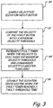
- FIG. 3 is a flow diagram for a process of managing a malfunction of encoder 36 according to the present invention.
- Controller 18 processes the feedback signal provided by encoder 36 to sample the velocity of hoist motor 12 (step 60). If the commanded velocity is greater than zero, but the velocity feedback from encoder 36 is less than a minimum velocity threshold (step 62), a fault bit is set in controller 18. In one embodiment, the minimum threshold velocity is about 1 mm/s. If the velocity feedback from encoder 36 is greater than or equal to the minimum velocity threshold, the fault bit is cleared.
- Controller 18 samples the fault bit periodically (e.g., every 10 ms) and increments a fault timer if the fault bit is set (step 64). If the fault bit is cleared when controller 18 samples the fault bit, the fault timer is cleared.
- controller 18 immediately disables inverter 22 and engages brake 34 to prevent unintended motion of elevator car 26 (step 66).
- a fault threshold period of time e.g. 300 ms
- controller 18 immediately disables inverter 22 and engages brake 34 to prevent unintended motion of elevator car 26 (step 66).
- the present invention is useful for detecting and minimizing unintended motion of elevator car 26 at normal speed elevator runs, as well as low and high speed elevator runs.
- the fault threshold time is set low enough to quickly detect the malfunction of encoder 36 to minimize unintended motion of elevator car 14. In this way, the unintended motion of elevator car 14 can be limited to about 2 or 3 cm before brake 34 is engaged.
- the fault threshold period of time is set high enough to prevent nuisance fault events. For example, for a motionless elevator, the velocity feedback from encoder 36 becomes greater than 1 mm/s about 200 ms after the commanded velocity becomes non-zero. Thus, by setting the fault threshold period of time at 300 ms, nuisance faults that may be caused when elevator 14 is put into motion are avoided.
- the position of hoist motor 12 may no longer be known.
- the position of the north pole magnet may not be known.
- controller 18 may set an attribute related to the position of the magnet in motor 14 being unknown. When operation of encoder 36 is re-established, controller 18 may then immediately determine the position of hoist motor 12 to ensure proper control over elevator 14 when brake 34 is disengaged.
- the present invention is directed to detecting and managing an encoder failure in an elevator drive system.
- a velocity of the elevator drive system is provided by an encoder signal and compared with a minimum velocity threshold.
- An encoder fault timer is incremented when the velocity is less than the minimum velocity threshold.
- the elevator drive system is disabled when the encoder fault timer reaches a fault threshold time.
- the fault threshold time is set high enough to prevent nuisance fault events, but low enough to quickly detect the encoder failure to minimize unintended motion of the elevator car.
Description
- The present invention relates to elevators and elevator systems. In particular, the present invention relates to managing an encoder failure in an elevator drive system.
- Elevator systems utilizing synchronous motor elevator machines need to detect absolute angular rotor position relative to the stator pole windings to be able to achieve maximum torque. An encoder, such as an incremental encoder, may be connected to the motor to track the position of the magnet in the rotor and provide a feedback signal indicative of the position and velocity to a signal processor in the elevator system. If the feedback signal from the encoder is lost (e.g., due to a power failure), the position of the rotor is no longer known to the elevator drive system.
- Because this limits the control that the elevator drive system has over the motor, the elevator brake is engaged to hold the elevator car in position, and the drive is disabled. However, the time between the loss of the encoder feedback signal and detection of this condition can be substantial, resulting in uncontrolled motion of the elevator car of up to two meters.
-
US 4898263 describes an elevator system for self-diagnosing problems with components and relevant methods for dealing with failures, for example encoder and vane failures. -
JP 2002 284460 - According to the present invention there is provided a method as defined by claim 1 and a system as defined by claim 7.
- The present invention is directed to detecting and managing an encoder failure in an elevator drive system. A velocity of the elevator drive system is provided by an encoder signal and compared with a minimum velocity threshold. An encoder fault timer is incremented when the velocity is less than the minimum velocity threshold. The elevator drive system is disabled when the encoder fault timer reaches a fault threshold time.
- Preferably disabling the elevator drive system comprises disabling a drive inverter in the elevator drive system.
- Preferably disabling the elevator drive system comprises engaging a brake to prevent motion of a drive sheave in the elevator drive system.
- Preferably the minimum velocity threshold is about one millimeter per second.
- Preferably the fault threshold time is about 300 milliseconds.
- Preferably the comparing step comprises setting a fault bit in an elevator drive processor when the sensed velocity is less than the minimum velocity threshold and clearing the fault bit in the elevator drive processor when the sense velocity is at least the minimum velocity threshold.
- Further preferably the incrementing step comprises incrementing the encoder fault timer when the fault bit is set.
- The method may further comprise resetting the encoder fault timer when the sensed velocity is at least the minimum velocity threshold.
- There is disclosed herein a system comprising: an elevator hoist machine including a motor, a rotating member driven by the motor for actuating a rope that connects an elevator car and a counterweight, and a brake for preventing the rotating member from rotating; an encoder operatively connected to the motor for providing a signal related to a position and velocity of the motor; and a drive controller for receiving the signal from the encoder and disabling the motor and engaging the brake when the velocity of the motor remains below a velocity threshold for a fault threshold time.
- Preferably the drive controller increments an encoder fault timer when the velocity of the motor is less than the velocity threshold and resets the encoder fault timer when the velocity is at least the velocity threshold.
- Further preferably the drive controller includes a register in which a fault bit is set when the velocity of the motor is less than the velocity of threshold and the fault bit is cleared when the velocity of the motor is at least the velocity threshold.
- Further preferably the drive controller increments the encoder fault timer when the fault bit is set and resets the encoder fault timer when the fault bit is cleared.
- In various embodiments the velocity threshold may be about one millimeter per second.
-
-
FIG. 1 is a schematic view of an elevator drive system including an encoder operatively connected to an elevator hoist motor. -
FIG. 2 is a functional diagram of an example incremental encoder for use in conjunction with the elevator power system shown inFIG. 1 . -
FIG. 3 is a flow diagram for a process of managing an encoder malfunction according to the present invention. -
FIG. 1 is a schematic view ofelevator drive system 10 for drivinghoist motor 12 of elevator 14 from AC power line 16, which may be connected to an electrical utility, such as from a commercial power source.Elevator drive system 10 includescontroller 18,converter 20, andinverter 22. DC bus 24 connectsconverter 20 andinverter 22. - Elevator 14 includes
elevator car 26 andcounterweight 28 that are connected through rope 30 acrosssheave 32. Brake 34 engagessheave 32 to prevent motion ofelevator car 26 andcounterweight 28.Encoder 36 is mounted coaxially withsheave 32.Controller 18 is connected toconverter 20,inverter 22, andencoder 36. - Power line 16 provides three-phase AC power to converter 20.
Converter 20 is a three-phase power converter that is operable to convert three-phase AC power from power supply 16 to DC power and provide the DC power toDC bus 24. In addition,converter 20 is operable to invert power onDC bus 24 to be returned to power supply 16. It should be noted that while power supply 16 is shown as a three-phase AC power supply,elevator drive system 10 may be adapted to receive power from any type of power source, including a single phase AC power source and a DC power source. -
Inverter 22 is a three-phase power inverter that is operable to invert DC power fromDC bus 24 to three-phase AC power. The three-phase AC power at the outputs ofinverter 22 is provided to hoistmotor 12. In addition,inverter 22 is operable to rectify power from hoistmotor 12 toDC bus 24 that is generated when elevator 14 drives hoistmotor 12. - Elevator 14 includes
elevator car 26 andcounterweight 28 that are connected through rope 30 to move concurrently and in opposite directions within an elevator hoistway.Counterweight 28 balances the load ofelevator car 26 and facilitates movement ofelevator car 26. Hoistmotor 12drives sheave 32 to produce linear movement ofelevator car 12 and counterweight 14.Motor 12 drives sheave 32 based on drive signals received frominverter 22 as controlled bycontroller 18. The magnitude and direction of force (i.e., torque) provided bymotor 12 on rope 30 controls the speed and direction ofelevator car 26, as well as the acceleration and deceleration ofelevator car 26.Encoder 36 is connected coaxially withsheave 32 to provide signals to controller 18 related to the direction of motion, speed, and acceleration of, and the distance travelled by,elevator car 26.
FIG. 2 is a functional diagram of anexample encoder 36 for use in conjunction withelevator drive system 10.Encoder 36 includes anouter track 40 of equally sizedopenings 42 spaced apart by equally sizedmasked regions 44.Encoder 36 also includesinner track 46 ofalternating openings 48 andmasked regions 50.Openings masked regions regions 50 ofinner track 48 are offset fromopenings 42 ofouter track 40. -
Encoder 36 includes a light source and a light detector (not shown) associated with each ofouter track 40 andinner track 46. The light source and light detector are disposed on opposite sides of the encoder track such that electrical signals are produced by the light detector whenencoder 36 rotates through and chops the light beam from the light source. These signals are provided by the light detectors forouter track 40 andinner track 46 to controller 18 to provide motion feedback regardingelevator car 26. More specifically, the amount of rotation byencoder 36 may be determined by counting the number of signal pulses generated by the light detector. This can then be converted to determine the linear distance travelled byelevator car 26. In addition, the order in which the electrical signals are received from the light detectors can be used to determine the direction of motion ofelevator car 26. Furthermore, the rate at which the signals from the light detectors are received can be converted to determine the speed and acceleration ofelevator car 26. It should be noted thatencoder 36 shown inFIG. 2 is merely illustrative, and many types of encoders capable of providing signals related to the motion of elevator 14 may be used in conjunction withelevator power system 10. - The motion information provided by
encoder 36 tocontroller 18 is used in driving hoistmotor 12. That is,controller 18 compares the velocity and motion feedback provided by the signals fromencoder 36 to a commanded velocity and direction of motion for elevator 14. The commanded velocity and direction of motion for elevator 14 is based on efficient dispatching ofelevator car 26 based on elevator demands. -
Controller 18 then operatesinverter 22 to drive hoistmotor 12 such that the actual velocity and direction of motion of elevator 14 matches the commanded velocity and direction of motion. - If
encoder 36 fails, such as due to a power failure or a component failure, the velocity feedback provided byencoder 36 drops to zero or close to zero. When this occurs, uncontrolled or unintended motion ofelevator car 26 may occur. For example, in a permanent magnet hoist motor, the position of the north pole magnet position (which is provided by the encoder signal) needs to be known to properly control hoistmotor 12 andelevator car 26. If the signal fromencoder 36 is lost,elevator drive system 10 may temporarily lose control of hoistmotor 12 until motion ofelevator car 26 is detected andbrake 34 is engaged to prevent motion ofsheave 32. The magnitude of the uncontrolled motion may be two meters or more beforebrake 34 is engaged. -
FIG. 3 is a flow diagram for a process of managing a malfunction ofencoder 36 according to the present invention.Controller 18 processes the feedback signal provided byencoder 36 to sample the velocity of hoist motor 12 (step 60). If the commanded velocity is greater than zero, but the velocity feedback fromencoder 36 is less than a minimum velocity threshold (step 62), a fault bit is set incontroller 18. In one embodiment, the minimum threshold velocity is about 1 mm/s. If the velocity feedback fromencoder 36 is greater than or equal to the minimum velocity threshold, the fault bit is cleared. -
Controller 18 samples the fault bit periodically (e.g., every 10 ms) and increments a fault timer if the fault bit is set (step 64). If the fault bit is cleared whencontroller 18 samples the fault bit, the fault timer is cleared. - If the fault bit is set for a fault threshold period of time (e.g., 300 ms),
controller 18 immediately disablesinverter 22 and engagesbrake 34 to prevent unintended motion of elevator car 26 (step 66). The present invention is useful for detecting and minimizing unintended motion ofelevator car 26 at normal speed elevator runs, as well as low and high speed elevator runs. - The fault threshold time is set low enough to quickly detect the malfunction of
encoder 36 to minimize unintended motion of elevator car 14. In this way, the unintended motion of elevator car 14 can be limited to about 2 or 3 cm beforebrake 34 is engaged. In addition, the fault threshold period of time is set high enough to prevent nuisance fault events. For example, for a motionless elevator, the velocity feedback fromencoder 36 becomes greater than 1 mm/s about 200 ms after the commanded velocity becomes non-zero. Thus, by setting the fault threshold period of time at 300 ms, nuisance faults that may be caused when elevator 14 is put into motion are avoided. - In addition, in the event of a failure of
encoder 36, the position of hoistmotor 12 may no longer be known. For example, in a permanent magnet motor the position of the north pole magnet may not be known. If the fault threshold time is reached,controller 18 may set an attribute related to the position of the magnet in motor 14 being unknown. When operation ofencoder 36 is re-established,controller 18 may then immediately determine the position of hoistmotor 12 to ensure proper control over elevator 14 whenbrake 34 is disengaged. - In summary, the present invention is directed to detecting and managing an encoder failure in an elevator drive system. A velocity of the elevator drive system is provided by an encoder signal and compared with a minimum velocity threshold. An encoder fault timer is incremented when the velocity is less than the minimum velocity threshold. The elevator drive system is disabled when the encoder fault timer reaches a fault threshold time. The fault threshold time is set high enough to prevent nuisance fault events, but low enough to quickly detect the encoder failure to minimize unintended motion of the elevator car.
- Although the present invention has been described with reference to examples and preferred embodiments, workers skilled in the art will recognize that changes may be made in form and detail without departing from the scope of the invention as defined by the following claims.
Claims (9)
- A method for controlling an elevator drive system (10), the method comprising:monitoring a velocity of the elevator drive system (10);disabling a drive inverter (22) in the elevator drive system (10) when the velocity remains below a velocity threshold for a fault threshold time; andengaging a sheave brake (34) to prevent motion of a drive sheave (32) in the elevator drive system (10), and characterised by:the monitoring step comprising:sensing velocity of the elevator drive system (10);comparing the velocity with the velocity threshold; andincrementing an encoder fault timer when the velocity is less than the velocity threshold.
- The method of claim 1, wherein the comparing step comprises:setting a fault bit in an elevator drive processor when the velocity is less than the velocity threshold; andclearing the fault bit in the elevator drive processor when the velocity is at least the velocity threshold.
- The method of claim 1 or 2, wherein the incrementing step comprises incrementing the encoder fault timer when the fault bit is set.
- The method of any preceding claim, and further comprising:resetting the encoder fault timer when the velocity is at least the velocity threshold.
- The method of any preceding claim, wherein the velocity threshold is about one mm/s.
- The method of any preceding claim, wherein the fault threshold time is about 300 ms.
- A system comprising:an elevator hoist machine including a motor (12), a rotating member (32) driven by the motor (12) for actuating a rope (30) that connects an elevator car (26) and a counterweight (28), and a brake (34) for preventing the rotating member (32) from rotating;an encoder (36) operatively connected to the motor (12) for providing a signal related to a position and velocity of the motor (12); anda drive controller (18) for receiving the signal from the encoder (36), controlling the motor (12) as a function of a commanded speed and the signal from the encoder (36), and characterised by disabling the motor (12) and engaging the brake (34) after the velocity of the motor (12) indicated by the signal from the encoder (36) remains below a velocity threshold for a fault threshold time while the commanded speed is greater than zero; andcharacterised in that the drive controller (18) increments an encoder fault time when the commanded velocity is greater than zero and the velocity of the motor (12) indicated by the signal from the encoder (36) is less than the velocity threshold.
- The system of claim 7, wherein the drive controller (18) rests the encoder fault timer when the commanded velocity is greater than zero and the velocity of the motor (12) indicated by the signal from the encoder (36) is at least the velocity threshold.
- The system of claim 8, wherein the drive controller (18) includes a register in which a fault bit is set when the velocity of the motor (12) indicated by the signal from the encoder (36) is less than the velocity threshold and the commanded velocity is greater than zero, and the fault bit is cleared when the velocity of the motor (12) indicated by the signal from the encoder (36) is at least the velocity threshold and the commanded velocity is greater than zero.
Priority Applications (2)
| Application Number | Priority Date | Filing Date | Title |
|---|---|---|---|
| ES12177918.5T ES2636675T3 (en) | 2006-01-30 | 2006-01-30 | Management of a malfunction of encoder in an elevator drive system |
| EP12177918.5A EP2517997B1 (en) | 2006-01-30 | 2006-01-30 | Managing an encoder malfunction in an elevator drive system |
Applications Claiming Priority (3)
| Application Number | Priority Date | Filing Date | Title |
|---|---|---|---|
| EP06719875.4A EP1981795B1 (en) | 2006-01-30 | 2006-01-30 | Managing an encoder malfunction in an elevator drive system |
| PCT/US2006/003223 WO2007086872A1 (en) | 2006-01-30 | 2006-01-30 | Managing an encoder malfunction in an elevator drive system |
| EP12177918.5A EP2517997B1 (en) | 2006-01-30 | 2006-01-30 | Managing an encoder malfunction in an elevator drive system |
Related Parent Applications (3)
| Application Number | Title | Priority Date | Filing Date |
|---|---|---|---|
| EP06719875.4 Division | 2006-01-30 | ||
| EP06719875.4A Division-Into EP1981795B1 (en) | 2006-01-30 | 2006-01-30 | Managing an encoder malfunction in an elevator drive system |
| EP06719875.4A Division EP1981795B1 (en) | 2006-01-30 | 2006-01-30 | Managing an encoder malfunction in an elevator drive system |
Publications (2)
| Publication Number | Publication Date |
|---|---|
| EP2517997A1 EP2517997A1 (en) | 2012-10-31 |
| EP2517997B1 true EP2517997B1 (en) | 2017-07-26 |
Family
ID=38309528
Family Applications (2)
| Application Number | Title | Priority Date | Filing Date |
|---|---|---|---|
| EP06719875.4A Active EP1981795B1 (en) | 2006-01-30 | 2006-01-30 | Managing an encoder malfunction in an elevator drive system |
| EP12177918.5A Active EP2517997B1 (en) | 2006-01-30 | 2006-01-30 | Managing an encoder malfunction in an elevator drive system |
Family Applications Before (1)
| Application Number | Title | Priority Date | Filing Date |
|---|---|---|---|
| EP06719875.4A Active EP1981795B1 (en) | 2006-01-30 | 2006-01-30 | Managing an encoder malfunction in an elevator drive system |
Country Status (7)
| Country | Link |
|---|---|
| US (1) | US8006808B2 (en) |
| EP (2) | EP1981795B1 (en) |
| JP (1) | JP2009525239A (en) |
| CN (1) | CN101336203B (en) |
| ES (2) | ES2459765T3 (en) |
| HK (1) | HK1127586A1 (en) |
| WO (1) | WO2007086872A1 (en) |
Families Citing this family (12)
| Publication number | Priority date | Publication date | Assignee | Title |
|---|---|---|---|---|
| US7690483B2 (en) * | 2005-01-11 | 2010-04-06 | Otis Elevator Company | Elevator including elevator rescue system |
| ES2536702T3 (en) * | 2009-12-22 | 2015-05-27 | Inventio Ag | Procedure and device for determining the movement and / or position of an elevator car |
| SI2807103T1 (en) * | 2012-01-25 | 2016-04-29 | Inventio Ag | Safety device and control method for a lift system |
| CN103076036B (en) * | 2012-12-31 | 2017-09-19 | 深圳市配天智造装备股份有限公司 | A kind of incremental encoder disconnection detection method and system |
| KR102060831B1 (en) | 2013-02-27 | 2019-12-30 | 삼성전자주식회사 | Flip chip packaging method, flux head using the same and flux head manufacturing method thereof |
| CN104310148B (en) * | 2014-09-24 | 2016-08-10 | 深圳市正弦电气股份有限公司 | A kind of elevator rescue method and device |
| US10689226B2 (en) * | 2015-02-04 | 2020-06-23 | Otis Elevator Company | Position determining system for multicar ropeless elevator system |
| EP3133037B1 (en) * | 2015-08-18 | 2018-10-10 | Kone Corporation | Method for moving an elevator car |
| EP3415454B1 (en) * | 2017-06-14 | 2021-09-22 | KONE Corporation | Automatic fault clearing for elevators, escalators and automatic doors |
| US11548758B2 (en) | 2017-06-30 | 2023-01-10 | Otis Elevator Company | Health monitoring systems and methods for elevator systems |
| CN110510463A (en) * | 2019-07-18 | 2019-11-29 | 特斯联(北京)科技有限公司 | A kind of elevator control system and method based on UWB |
| CN111722615A (en) * | 2020-06-15 | 2020-09-29 | 珠海格力电器股份有限公司 | Fault clearing device of servo drive controller and control method thereof |
Citations (1)
| Publication number | Priority date | Publication date | Assignee | Title |
|---|---|---|---|---|
| JP2002284460A (en) * | 2001-03-22 | 2002-10-03 | Mitsubishi Electric Corp | Abnormality detecting device for speed detector in elevator |
Family Cites Families (20)
| Publication number | Priority date | Publication date | Assignee | Title |
|---|---|---|---|---|
| JPS58193873A (en) * | 1982-05-07 | 1983-11-11 | 三菱電機株式会社 | Abnormality message device for elevator |
| JPS61248883A (en) * | 1985-04-25 | 1986-11-06 | 株式会社東芝 | Trouble detector for elevator |
| US4898263A (en) | 1988-09-12 | 1990-02-06 | Montgomery Elevator Company | Elevator self-diagnostic control system |
| JPH04313583A (en) * | 1991-04-10 | 1992-11-05 | Toshiba Corp | Control device for private residence elevator |
| US5631452A (en) | 1994-08-18 | 1997-05-20 | Otis Elevator Company | System for position loss recovery for an elevator car |
| DE69622655T2 (en) * | 1995-10-05 | 2003-04-03 | Otis Elevator Co | Fault detector for elevator drives |
| US5900596A (en) * | 1995-10-06 | 1999-05-04 | Inventio Ag | Hydraulic brake controller |
| JP4015721B2 (en) * | 1997-05-19 | 2007-11-28 | 株式会社日立製作所 | Elevator door control device |
| US6397974B1 (en) | 1998-10-09 | 2002-06-04 | Otis Elevator Company | Traction elevator system using flexible, flat rope and a permanent magnet machine |
| JP3547977B2 (en) * | 1998-02-27 | 2004-07-28 | 株式会社ナブコ | Remote monitoring system for automatic door systems |
| US6484125B1 (en) * | 2000-05-09 | 2002-11-19 | Otis Elevator Company | Service information derived from elevator operational parameters |
| US6330936B1 (en) * | 2000-05-09 | 2001-12-18 | Otis Elevator Company | Elevator behavior reported in occurrence-related groups |
| US6492788B1 (en) | 2000-11-10 | 2002-12-10 | Otis Elevator Company | Method and apparatus for encoderless operation of a permanent magnet synchronous motor in an elevator |
| US6401875B1 (en) | 2001-02-12 | 2002-06-11 | Otis Elevator Company | Absolute position sensing method and apparatus for synchronous elevator machines by detection stator iron saturation |
| US6683432B2 (en) * | 2001-09-12 | 2004-01-27 | Eigenpoint Company | Safety circuit with automatic recovery |
| US6604611B2 (en) * | 2001-12-28 | 2003-08-12 | Otis Elevator Company | Condition-based, auto-thresholded elevator maintenance |
| WO2005102898A1 (en) * | 2004-03-30 | 2005-11-03 | Mitsubishi Denki Kabushiki Kaisha | Control device of elevator |
| EP2258650B1 (en) * | 2004-04-30 | 2012-08-22 | Mitsubishi Denki Kabushiki Kaisha | Emergency braking system for an elevator |
| JP2005335913A (en) * | 2004-05-28 | 2005-12-08 | Mitsubishi Electric Corp | Elevator device |
| DE102004050647B4 (en) * | 2004-10-18 | 2014-11-20 | Siemens Aktiengesellschaft | Monitoring method for a drive device to a standstill, hereby corresponding monitoring device and hereby corresponding drive system |
-
2006
- 2006-01-30 US US12/087,694 patent/US8006808B2/en active Active
- 2006-01-30 ES ES06719875.4T patent/ES2459765T3/en active Active
- 2006-01-30 CN CN200680051945XA patent/CN101336203B/en active Active
- 2006-01-30 JP JP2008552282A patent/JP2009525239A/en not_active Withdrawn
- 2006-01-30 WO PCT/US2006/003223 patent/WO2007086872A1/en active Application Filing
- 2006-01-30 EP EP06719875.4A patent/EP1981795B1/en active Active
- 2006-01-30 ES ES12177918.5T patent/ES2636675T3/en active Active
- 2006-01-30 EP EP12177918.5A patent/EP2517997B1/en active Active
-
2009
- 2009-06-17 HK HK09105451.2A patent/HK1127586A1/en not_active IP Right Cessation
Patent Citations (1)
| Publication number | Priority date | Publication date | Assignee | Title |
|---|---|---|---|---|
| JP2002284460A (en) * | 2001-03-22 | 2002-10-03 | Mitsubishi Electric Corp | Abnormality detecting device for speed detector in elevator |
Also Published As
| Publication number | Publication date |
|---|---|
| WO2007086872A1 (en) | 2007-08-02 |
| EP1981795B1 (en) | 2014-04-16 |
| ES2636675T3 (en) | 2017-10-06 |
| ES2459765T3 (en) | 2014-05-12 |
| CN101336203B (en) | 2011-04-20 |
| HK1127586A1 (en) | 2009-10-02 |
| CN101336203A (en) | 2008-12-31 |
| JP2009525239A (en) | 2009-07-09 |
| US8006808B2 (en) | 2011-08-30 |
| EP2517997A1 (en) | 2012-10-31 |
| US20090000877A1 (en) | 2009-01-01 |
| EP1981795A1 (en) | 2008-10-22 |
| EP1981795A4 (en) | 2011-10-05 |
Similar Documents
| Publication | Publication Date | Title |
|---|---|---|
| EP2517997B1 (en) | Managing an encoder malfunction in an elevator drive system | |
| JP4468224B2 (en) | Elevator position detection system and method | |
| US7353916B2 (en) | Elevator supervision | |
| DK2189410T3 (en) | Elevator Monitoring | |
| EP3599200B1 (en) | Elevator | |
| JP5932577B2 (en) | Elevator safety system | |
| JP6317077B2 (en) | Elevator safety system | |
| JP5602613B2 (en) | Elevator equipment | |
| JP2008230770A (en) | Safety system of elevator | |
| KR20040099428A (en) | Elevator control system | |
| EP2687471B1 (en) | Elevator control device | |
| CN101254878A (en) | Elevator system | |
| US11554933B2 (en) | Elevator | |
| CN101674996B (en) | Elevator | |
| EP2147883B1 (en) | Elevator apparatus | |
| JP2001039639A (en) | Position detecting device for elevator | |
| JP5084113B2 (en) | Elevator device abnormality detection device | |
| WO2020245495A1 (en) | Control of an elevator system |
Legal Events
| Date | Code | Title | Description |
|---|---|---|---|
| PUAI | Public reference made under article 153(3) epc to a published international application that has entered the european phase |
Free format text: ORIGINAL CODE: 0009012 |
|
| AC | Divisional application: reference to earlier application |
Ref document number: 1981795 Country of ref document: EP Kind code of ref document: P |
|
| AK | Designated contracting states |
Kind code of ref document: A1 Designated state(s): AT BE BG CH CY CZ DE DK EE ES FI FR GB GR HU IE IS IT LI LT LU LV MC NL PL PT RO SE SI SK TR |
|
| 17P | Request for examination filed |
Effective date: 20130328 |
|
| 17Q | First examination report despatched |
Effective date: 20131107 |
|
| GRAP | Despatch of communication of intention to grant a patent |
Free format text: ORIGINAL CODE: EPIDOSNIGR1 |
|
| INTG | Intention to grant announced |
Effective date: 20160729 |
|
| STAA | Information on the status of an ep patent application or granted ep patent |
Free format text: STATUS: GRANT OF PATENT IS INTENDED |
|
| GRAS | Grant fee paid |
Free format text: ORIGINAL CODE: EPIDOSNIGR3 |
|
| GRAA | (expected) grant |
Free format text: ORIGINAL CODE: 0009210 |
|
| STAA | Information on the status of an ep patent application or granted ep patent |
Free format text: STATUS: THE PATENT HAS BEEN GRANTED |
|
| AC | Divisional application: reference to earlier application |
Ref document number: 1981795 Country of ref document: EP Kind code of ref document: P |
|
| AK | Designated contracting states |
Kind code of ref document: B1 Designated state(s): AT BE BG CH CY CZ DE DK EE ES FI FR GB GR HU IE IS IT LI LT LU LV MC NL PL PT RO SE SI SK TR |
|
| REG | Reference to a national code |
Ref country code: GB Ref legal event code: FG4D |
|
| REG | Reference to a national code |
Ref country code: CH Ref legal event code: EP |
|
| REG | Reference to a national code |
Ref country code: DE Ref legal event code: R082 Ref document number: 602006053169 Country of ref document: DE Representative=s name: SCHMITT-NILSON SCHRAUD WAIBEL WOHLFROM PATENTA, DE |
|
| REG | Reference to a national code |
Ref country code: AT Ref legal event code: REF Ref document number: 912173 Country of ref document: AT Kind code of ref document: T Effective date: 20170815 |
|
| REG | Reference to a national code |
Ref country code: IE Ref legal event code: FG4D |
|
| RAP2 | Party data changed (patent owner data changed or rights of a patent transferred) |
Owner name: OTIS ELEVATOR COMPANY |
|
| REG | Reference to a national code |
Ref country code: DE Ref legal event code: R096 Ref document number: 602006053169 Country of ref document: DE |
|
| REG | Reference to a national code |
Ref country code: ES Ref legal event code: FG2A Ref document number: 2636675 Country of ref document: ES Kind code of ref document: T3 Effective date: 20171006 |
|
| REG | Reference to a national code |
Ref country code: NL Ref legal event code: MP Effective date: 20170726 |
|
| REG | Reference to a national code |
Ref country code: LT Ref legal event code: MG4D |
|
| REG | Reference to a national code |
Ref country code: AT Ref legal event code: MK05 Ref document number: 912173 Country of ref document: AT Kind code of ref document: T Effective date: 20170726 |
|
| REG | Reference to a national code |
Ref country code: FR Ref legal event code: PLFP Year of fee payment: 13 |
|
| PG25 | Lapsed in a contracting state [announced via postgrant information from national office to epo] |
Ref country code: NL Free format text: LAPSE BECAUSE OF FAILURE TO SUBMIT A TRANSLATION OF THE DESCRIPTION OR TO PAY THE FEE WITHIN THE PRESCRIBED TIME-LIMIT Effective date: 20170726 Ref country code: FI Free format text: LAPSE BECAUSE OF FAILURE TO SUBMIT A TRANSLATION OF THE DESCRIPTION OR TO PAY THE FEE WITHIN THE PRESCRIBED TIME-LIMIT Effective date: 20170726 Ref country code: AT Free format text: LAPSE BECAUSE OF FAILURE TO SUBMIT A TRANSLATION OF THE DESCRIPTION OR TO PAY THE FEE WITHIN THE PRESCRIBED TIME-LIMIT Effective date: 20170726 Ref country code: SE Free format text: LAPSE BECAUSE OF FAILURE TO SUBMIT A TRANSLATION OF THE DESCRIPTION OR TO PAY THE FEE WITHIN THE PRESCRIBED TIME-LIMIT Effective date: 20170726 Ref country code: LT Free format text: LAPSE BECAUSE OF FAILURE TO SUBMIT A TRANSLATION OF THE DESCRIPTION OR TO PAY THE FEE WITHIN THE PRESCRIBED TIME-LIMIT Effective date: 20170726 |
|
| PG25 | Lapsed in a contracting state [announced via postgrant information from national office to epo] |
Ref country code: LV Free format text: LAPSE BECAUSE OF FAILURE TO SUBMIT A TRANSLATION OF THE DESCRIPTION OR TO PAY THE FEE WITHIN THE PRESCRIBED TIME-LIMIT Effective date: 20170726 Ref country code: IS Free format text: LAPSE BECAUSE OF FAILURE TO SUBMIT A TRANSLATION OF THE DESCRIPTION OR TO PAY THE FEE WITHIN THE PRESCRIBED TIME-LIMIT Effective date: 20171126 Ref country code: BG Free format text: LAPSE BECAUSE OF FAILURE TO SUBMIT A TRANSLATION OF THE DESCRIPTION OR TO PAY THE FEE WITHIN THE PRESCRIBED TIME-LIMIT Effective date: 20171026 Ref country code: PL Free format text: LAPSE BECAUSE OF FAILURE TO SUBMIT A TRANSLATION OF THE DESCRIPTION OR TO PAY THE FEE WITHIN THE PRESCRIBED TIME-LIMIT Effective date: 20170726 Ref country code: GR Free format text: LAPSE BECAUSE OF FAILURE TO SUBMIT A TRANSLATION OF THE DESCRIPTION OR TO PAY THE FEE WITHIN THE PRESCRIBED TIME-LIMIT Effective date: 20171027 |
|
| PG25 | Lapsed in a contracting state [announced via postgrant information from national office to epo] |
Ref country code: RO Free format text: LAPSE BECAUSE OF FAILURE TO SUBMIT A TRANSLATION OF THE DESCRIPTION OR TO PAY THE FEE WITHIN THE PRESCRIBED TIME-LIMIT Effective date: 20170726 Ref country code: CZ Free format text: LAPSE BECAUSE OF FAILURE TO SUBMIT A TRANSLATION OF THE DESCRIPTION OR TO PAY THE FEE WITHIN THE PRESCRIBED TIME-LIMIT Effective date: 20170726 Ref country code: DK Free format text: LAPSE BECAUSE OF FAILURE TO SUBMIT A TRANSLATION OF THE DESCRIPTION OR TO PAY THE FEE WITHIN THE PRESCRIBED TIME-LIMIT Effective date: 20170726 |
|
| REG | Reference to a national code |
Ref country code: DE Ref legal event code: R097 Ref document number: 602006053169 Country of ref document: DE |
|
| PG25 | Lapsed in a contracting state [announced via postgrant information from national office to epo] |
Ref country code: IT Free format text: LAPSE BECAUSE OF FAILURE TO SUBMIT A TRANSLATION OF THE DESCRIPTION OR TO PAY THE FEE WITHIN THE PRESCRIBED TIME-LIMIT Effective date: 20170726 Ref country code: SK Free format text: LAPSE BECAUSE OF FAILURE TO SUBMIT A TRANSLATION OF THE DESCRIPTION OR TO PAY THE FEE WITHIN THE PRESCRIBED TIME-LIMIT Effective date: 20170726 Ref country code: EE Free format text: LAPSE BECAUSE OF FAILURE TO SUBMIT A TRANSLATION OF THE DESCRIPTION OR TO PAY THE FEE WITHIN THE PRESCRIBED TIME-LIMIT Effective date: 20170726 |
|
| PLBE | No opposition filed within time limit |
Free format text: ORIGINAL CODE: 0009261 |
|
| STAA | Information on the status of an ep patent application or granted ep patent |
Free format text: STATUS: NO OPPOSITION FILED WITHIN TIME LIMIT |
|
| 26N | No opposition filed |
Effective date: 20180430 |
|
| PG25 | Lapsed in a contracting state [announced via postgrant information from national office to epo] |
Ref country code: SI Free format text: LAPSE BECAUSE OF FAILURE TO SUBMIT A TRANSLATION OF THE DESCRIPTION OR TO PAY THE FEE WITHIN THE PRESCRIBED TIME-LIMIT Effective date: 20170726 |
|
| REG | Reference to a national code |
Ref country code: CH Ref legal event code: PL |
|
| GBPC | Gb: european patent ceased through non-payment of renewal fee |
Effective date: 20180130 |
|
| PG25 | Lapsed in a contracting state [announced via postgrant information from national office to epo] |
Ref country code: LU Free format text: LAPSE BECAUSE OF NON-PAYMENT OF DUE FEES Effective date: 20180130 |
|
| REG | Reference to a national code |
Ref country code: IE Ref legal event code: MM4A |
|
| REG | Reference to a national code |
Ref country code: BE Ref legal event code: MM Effective date: 20180131 |
|
| PG25 | Lapsed in a contracting state [announced via postgrant information from national office to epo] |
Ref country code: BE Free format text: LAPSE BECAUSE OF NON-PAYMENT OF DUE FEES Effective date: 20180131 Ref country code: CH Free format text: LAPSE BECAUSE OF NON-PAYMENT OF DUE FEES Effective date: 20180131 Ref country code: GB Free format text: LAPSE BECAUSE OF NON-PAYMENT OF DUE FEES Effective date: 20180130 Ref country code: LI Free format text: LAPSE BECAUSE OF NON-PAYMENT OF DUE FEES Effective date: 20180131 |
|
| PG25 | Lapsed in a contracting state [announced via postgrant information from national office to epo] |
Ref country code: IE Free format text: LAPSE BECAUSE OF NON-PAYMENT OF DUE FEES Effective date: 20180130 |
|
| PG25 | Lapsed in a contracting state [announced via postgrant information from national office to epo] |
Ref country code: MC Free format text: LAPSE BECAUSE OF FAILURE TO SUBMIT A TRANSLATION OF THE DESCRIPTION OR TO PAY THE FEE WITHIN THE PRESCRIBED TIME-LIMIT Effective date: 20170726 |
|
| PG25 | Lapsed in a contracting state [announced via postgrant information from national office to epo] |
Ref country code: TR Free format text: LAPSE BECAUSE OF FAILURE TO SUBMIT A TRANSLATION OF THE DESCRIPTION OR TO PAY THE FEE WITHIN THE PRESCRIBED TIME-LIMIT Effective date: 20170726 |
|
| PG25 | Lapsed in a contracting state [announced via postgrant information from national office to epo] |
Ref country code: PT Free format text: LAPSE BECAUSE OF FAILURE TO SUBMIT A TRANSLATION OF THE DESCRIPTION OR TO PAY THE FEE WITHIN THE PRESCRIBED TIME-LIMIT Effective date: 20170726 Ref country code: HU Free format text: LAPSE BECAUSE OF FAILURE TO SUBMIT A TRANSLATION OF THE DESCRIPTION OR TO PAY THE FEE WITHIN THE PRESCRIBED TIME-LIMIT; INVALID AB INITIO Effective date: 20060130 |
|
| PG25 | Lapsed in a contracting state [announced via postgrant information from national office to epo] |
Ref country code: CY Free format text: LAPSE BECAUSE OF FAILURE TO SUBMIT A TRANSLATION OF THE DESCRIPTION OR TO PAY THE FEE WITHIN THE PRESCRIBED TIME-LIMIT Effective date: 20170726 |
|
| STAA | Information on the status of an ep patent application or granted ep patent |
Free format text: STATUS: NO OPPOSITION FILED WITHIN TIME LIMIT |
|
| PGFP | Annual fee paid to national office [announced via postgrant information from national office to epo] |
Ref country code: ES Payment date: 20230201 Year of fee payment: 18 |
|
| PGFP | Annual fee paid to national office [announced via postgrant information from national office to epo] |
Ref country code: DE Payment date: 20221220 Year of fee payment: 18 |
|
| PGFP | Annual fee paid to national office [announced via postgrant information from national office to epo] |
Ref country code: FR Payment date: 20231219 Year of fee payment: 19 |