EP1332908A1 - Accelerator pedal device - Google Patents
Accelerator pedal device Download PDFInfo
- Publication number
- EP1332908A1 EP1332908A1 EP01972631A EP01972631A EP1332908A1 EP 1332908 A1 EP1332908 A1 EP 1332908A1 EP 01972631 A EP01972631 A EP 01972631A EP 01972631 A EP01972631 A EP 01972631A EP 1332908 A1 EP1332908 A1 EP 1332908A1
- Authority
- EP
- European Patent Office
- Prior art keywords
- accelerator pedal
- pedal
- pedal arm
- accelerator
- range
- Prior art date
- Legal status (The legal status is an assumption and is not a legal conclusion. Google has not performed a legal analysis and makes no representation as to the accuracy of the status listed.)
- Granted
Links
Images


Classifications
-
- G—PHYSICS
- G05—CONTROLLING; REGULATING
- G05G—CONTROL DEVICES OR SYSTEMS INSOFAR AS CHARACTERISED BY MECHANICAL FEATURES ONLY
- G05G1/00—Controlling members, e.g. knobs or handles; Assemblies or arrangements thereof; Indicating position of controlling members
- G05G1/30—Controlling members actuated by foot
-
- B—PERFORMING OPERATIONS; TRANSPORTING
- B60—VEHICLES IN GENERAL
- B60K—ARRANGEMENT OR MOUNTING OF PROPULSION UNITS OR OF TRANSMISSIONS IN VEHICLES; ARRANGEMENT OR MOUNTING OF PLURAL DIVERSE PRIME-MOVERS IN VEHICLES; AUXILIARY DRIVES FOR VEHICLES; INSTRUMENTATION OR DASHBOARDS FOR VEHICLES; ARRANGEMENTS IN CONNECTION WITH COOLING, AIR INTAKE, GAS EXHAUST OR FUEL SUPPLY OF PROPULSION UNITS IN VEHICLES
- B60K26/00—Arrangement or mounting of propulsion-unit control devices in vehicles
- B60K26/02—Arrangement or mounting of propulsion-unit control devices in vehicles of initiating means or elements
-
- B—PERFORMING OPERATIONS; TRANSPORTING
- B60—VEHICLES IN GENERAL
- B60K—ARRANGEMENT OR MOUNTING OF PROPULSION UNITS OR OF TRANSMISSIONS IN VEHICLES; ARRANGEMENT OR MOUNTING OF PLURAL DIVERSE PRIME-MOVERS IN VEHICLES; AUXILIARY DRIVES FOR VEHICLES; INSTRUMENTATION OR DASHBOARDS FOR VEHICLES; ARRANGEMENTS IN CONNECTION WITH COOLING, AIR INTAKE, GAS EXHAUST OR FUEL SUPPLY OF PROPULSION UNITS IN VEHICLES
- B60K26/00—Arrangement or mounting of propulsion-unit control devices in vehicles
- B60K26/02—Arrangement or mounting of propulsion-unit control devices in vehicles of initiating means or elements
- B60K26/021—Arrangement or mounting of propulsion-unit control devices in vehicles of initiating means or elements with means for providing feel, e.g. by changing pedal force characteristics
-
- F—MECHANICAL ENGINEERING; LIGHTING; HEATING; WEAPONS; BLASTING
- F02—COMBUSTION ENGINES; HOT-GAS OR COMBUSTION-PRODUCT ENGINE PLANTS
- F02D—CONTROLLING COMBUSTION ENGINES
- F02D11/00—Arrangements for, or adaptations to, non-automatic engine control initiation means, e.g. operator initiated
- F02D11/02—Arrangements for, or adaptations to, non-automatic engine control initiation means, e.g. operator initiated characterised by hand, foot, or like operator controlled initiation means
-
- F—MECHANICAL ENGINEERING; LIGHTING; HEATING; WEAPONS; BLASTING
- F02—COMBUSTION ENGINES; HOT-GAS OR COMBUSTION-PRODUCT ENGINE PLANTS
- F02D—CONTROLLING COMBUSTION ENGINES
- F02D11/00—Arrangements for, or adaptations to, non-automatic engine control initiation means, e.g. operator initiated
- F02D11/04—Arrangements for, or adaptations to, non-automatic engine control initiation means, e.g. operator initiated characterised by mechanical control linkages
-
- F—MECHANICAL ENGINEERING; LIGHTING; HEATING; WEAPONS; BLASTING
- F02—COMBUSTION ENGINES; HOT-GAS OR COMBUSTION-PRODUCT ENGINE PLANTS
- F02D—CONTROLLING COMBUSTION ENGINES
- F02D11/00—Arrangements for, or adaptations to, non-automatic engine control initiation means, e.g. operator initiated
- F02D11/06—Arrangements for, or adaptations to, non-automatic engine control initiation means, e.g. operator initiated characterised by non-mechanical control linkages, e.g. fluid control linkages or by control linkages with power drive or assistance
- F02D11/10—Arrangements for, or adaptations to, non-automatic engine control initiation means, e.g. operator initiated characterised by non-mechanical control linkages, e.g. fluid control linkages or by control linkages with power drive or assistance of the electric type
- F02D11/105—Arrangements for, or adaptations to, non-automatic engine control initiation means, e.g. operator initiated characterised by non-mechanical control linkages, e.g. fluid control linkages or by control linkages with power drive or assistance of the electric type characterised by the function converting demand to actuation, e.g. a map indicating relations between an accelerator pedal position and throttle valve opening or target engine torque
-
- F—MECHANICAL ENGINEERING; LIGHTING; HEATING; WEAPONS; BLASTING
- F02—COMBUSTION ENGINES; HOT-GAS OR COMBUSTION-PRODUCT ENGINE PLANTS
- F02D—CONTROLLING COMBUSTION ENGINES
- F02D11/00—Arrangements for, or adaptations to, non-automatic engine control initiation means, e.g. operator initiated
- F02D11/06—Arrangements for, or adaptations to, non-automatic engine control initiation means, e.g. operator initiated characterised by non-mechanical control linkages, e.g. fluid control linkages or by control linkages with power drive or assistance
- F02D11/10—Arrangements for, or adaptations to, non-automatic engine control initiation means, e.g. operator initiated characterised by non-mechanical control linkages, e.g. fluid control linkages or by control linkages with power drive or assistance of the electric type
- F02D2011/101—Arrangements for, or adaptations to, non-automatic engine control initiation means, e.g. operator initiated characterised by non-mechanical control linkages, e.g. fluid control linkages or by control linkages with power drive or assistance of the electric type characterised by the means for actuating the throttles
- F02D2011/102—Arrangements for, or adaptations to, non-automatic engine control initiation means, e.g. operator initiated characterised by non-mechanical control linkages, e.g. fluid control linkages or by control linkages with power drive or assistance of the electric type characterised by the means for actuating the throttles at least one throttle being moved only by an electric actuator
-
- Y—GENERAL TAGGING OF NEW TECHNOLOGICAL DEVELOPMENTS; GENERAL TAGGING OF CROSS-SECTIONAL TECHNOLOGIES SPANNING OVER SEVERAL SECTIONS OF THE IPC; TECHNICAL SUBJECTS COVERED BY FORMER USPC CROSS-REFERENCE ART COLLECTIONS [XRACs] AND DIGESTS
- Y10—TECHNICAL SUBJECTS COVERED BY FORMER USPC
- Y10T—TECHNICAL SUBJECTS COVERED BY FORMER US CLASSIFICATION
- Y10T74/00—Machine element or mechanism
- Y10T74/20—Control lever and linkage systems
- Y10T74/20528—Foot operated
-
- Y—GENERAL TAGGING OF NEW TECHNOLOGICAL DEVELOPMENTS; GENERAL TAGGING OF CROSS-SECTIONAL TECHNOLOGIES SPANNING OVER SEVERAL SECTIONS OF THE IPC; TECHNICAL SUBJECTS COVERED BY FORMER USPC CROSS-REFERENCE ART COLLECTIONS [XRACs] AND DIGESTS
- Y10—TECHNICAL SUBJECTS COVERED BY FORMER USPC
- Y10T—TECHNICAL SUBJECTS COVERED BY FORMER US CLASSIFICATION
- Y10T74/00—Machine element or mechanism
- Y10T74/20—Control lever and linkage systems
- Y10T74/20528—Foot operated
- Y10T74/20534—Accelerator
Definitions
- the present invention relates to an accelerator pedal apparatus which is utilized for a vehicle etc. with a drive-by-wire system, and especially relates to an accelerator pedal apparatus having a sensor to detect depressing amount of the accelerator pedal.
- An electronic controlled throttle system namely, a drive by wire system is well-known as a system to control a combustion state, power, revolution and etc. of an engine mounted to a vehicle especially an automobile, more accurately and precisely than a driver intends to control the accelerator.
- an accelerator pedal and a throttle valve are not connected by an accelerator cable.
- the engine power is controlled based on electronic signals converted from the depressing amount of the accelerator pedal.
- a vehicle without a play to the operation of the accelerator pedal, a vehicle, with an automatic transmission for example, may have a possibility to start abruptly in case the throttle valve opens when the driver puts his foot on the accelerator pedal unconsciously without an intention of depressing. Accordingly, to prevent this phenomenon, the driver needs extra care for the accelerator operation, which causes unsuitable feeling with the operation of the accelerator pedal in comparison with the conventional accelerator pedal apparatus.
- the present invention is devised in the light of the abovementioned viewpoints, and the purpose is to provide an accelerator pedal apparatus which is easy to operate and has no unsuitable feeling with the accelerator pedal operation, with the structure being simple, compact and so on.
- the accelerator pedal apparatus of the present invention comprises a pedal arm which is supported movably from a resting position to a maximum depressing position by depressing force transmitted from an accelerator pedal, a return spring which urges the pedal arm to return toward the resting position, a friction generating mechanism which generates friction force in accordance with the movement of the pedal arm, and a detecting means which detects the depressing amount of the accelerator pedal, wherein a play range in which friction force equal to or larger than a specific level is not generated is set in the range where the pedal arm moves from the resting position by a specific amount, and an opening of a throttle valve is kept constant in the play range by a control means to control the opening of the throttle valve disposed at an intake system of an engine based on an output signal of the detecting means.
- the pedal arm when the accelerator pedal is depressed, the pedal arm firstly moves in the specific play range following the depression. Then when it moves further in excess of the play range, the friction force equal to or larger than a specific level is generated in accordance with the movement.
- the throttle valve is kept at a specific opening in the play range of the pedal arm (the accelerator pedal) by the signal of the control means. In the range over the play range, the throttle valve is controlled appropriately at the opening in accordance with the depressing amount of the accelerator pedal. In this manner, desirable operating feeling without unsuitable feeling with the accelerator pedal operation is obtained while the structure is being simplified.
- the accelerator pedal apparatus of the present invention comprises a pedal arm which is supported movably from a resting position to a maximum depressing position by depressing force transmitted from an accelerator pedal, a return spring which urges the pedal arm to return toward the resting position, a friction generating mechanism which generates friction force in accordance with the movement of the pedal arm, and a detecting means which detects the depressing amount of the accelerator pedal, wherein a play range in which friction force equal to or larger than a specific level is not generated is set in the range where the pedal arm moves from the resting position by a specific amount, and an output signal of the detecting means is kept constant in the play range.
- the pedal arm when the accelerator pedal is depressed, the pedal arm firstly moves in the specific play range following the depression. Then when it moves further in excess of the play range, the friction force equal to or larger than a specific level is generated in accordance with the movement.
- the signal of the control means in the play range of the pedal arm (the accelerator pedal), the signal of the control means is kept constant, resulting in that the throttle valve is kept at a specific opening.
- the signal of the control means increases in accordance with the depressing amount of the accelerator pedal, and then the throttle valve is controlled appropriately at the opening in accordance with the change. In this manner, desirable operating feeling without unsuitable feeling with the accelerator pedal operation is obtained while the structure is being simplified.
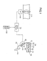
- Fig. 1 is a schematic of an accelerator pedal apparatus of the present invention.
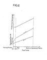
- Fig. 2 shows depressing force characteristics and throttle valve opening characteristics of the accelerator pedal.
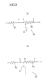
- Fig. 3 (a) and (b) are basic circuit diagrams of an accelerator position sensor.
- Fig. 4 shows output characteristics of the sensor corresponding to Fig. 2 (a).
- Fig. 5 shows output characteristics of the sensor corresponding to Fig. 2 (b).
- Fig. 6 is a graph showing depressing force characteristics and accelerator position sensor output characteristics of a conventional accelerator pedal apparatus.
- the accelerator pedal apparatus of the embodiment comprises a pedal arm 20 which is movable from a resting position to a maximum depressing position by depressing force transmitted from an accelerator pedal 10, a pedal shaft 30 which supports the pedal arm 20 free to swing, a return spring 40 which urges the pedal arm 20 to return toward the resting position, a friction generating mechanism 50 which generates friction force in accordance with the movement of the pedal arm 20, an accelerator position sensor 60 as a detecting means which detects the depressing amount of the accelerator pedal 10, and so on.
- a control means (a control segment) 70 drives a motor 100 appropriately based on the accelerator position sensor 60 output signals and so on, so that the opening of a throttle valve 110, which is disposed at an engine intake system, is controlled.
- a friction force generating mechanism 50 comprises a first movable friction member 52 and a second movable friction member 53 disposed in a sliding guide member 51 having an inclined surface respectively that faces each other, a play load spring 54 disposed between the first movable friction member 52 and the second movable friction member 53, a return spring to push back the second movable friction member 53 to a resting position, and so on.
- the control segment (the control means) 70 consists of a control unit in which a CPU is integrated. It controls the throttle valve 110 to be at the desired opening, by calculating variously based on programs or data maps stored in a memory segment 120 and transmitting control signals appropriately to the motor 100, after taking in signals of the accelerator position sensor 60, signals of various sensors to detect engine operating state, and so on.
- the accelerator position sensor 60 is a contact type position sensor with a variable resistor.
- a slider 61 moves in the range between B and C where a resistor 63 exists, as shown in Fig. 3 (a).
- the range between B and C corresponds to the movable range of the accelerator pedal 10 (the pedal arm 20), which is between the resting position and the maximum depressing position, namely, all of the play range and the friction generating range.
- the output signal increases linearly upward slant to the right in accordance with the depressing amount (pedal stroke) of the accelerator pedal 10, as shown in Fig. 4.
- a threshold V0 of the sensor output is set to the memory segment 120 in advance, so that the control segment 70 controls the throttle valve 110 to stay at idling opening when the output signal is equal to or less than the threshold.
- control segment 70 holds the opening of the throttle valve 110 constant (idling opening) in the play range, where the friction force that is equal to or larger than a specific level is not generated.
- the contact type position sensor shown in Fig. 3 (b) can be adopted as another accelerator position sensor 60'.
- the slider 61 moves in the range between A and B where no resistor exists, and the range between B and C where the resistor 63 exists.
- the slider 61 positions at point B, it is designed to correspond to the ending position of the play range, where the first movable friction member 52 contacts the second movable friction member 53. Consequently, the range between A and B corresponds to the play range of the friction force generating mechanism 50 (accelerator pedal 10), and the range between B and C corresponds to the range where the friction force being in excess of the play range is generated.
- control segment 70 holds the opening of the throttle valve 110 constant (idling opening) in the play range, where the friction force that is equal to or larger than a specific level is not generated.
- accelerator position senor 60 or 60' when a driver depresses the accelerator pedal 10 from the resting position, it is possible to recognize the position where the increasing characteristic of the depressing force changes caused by the generation of the friction force, namely the ending position of the play range, by the depressing feeling.
- the engine power control begins from that position. Hence, an operation without unsuitable feeling is obtained, and the accelerator pedal 10 can be operated safely.
- a contact type position sensor is adopted as the accelerator position sensor 60, 60'.
- a non-contact type position sensor which outputs position signals by utilizing magnetic flux.
- output gradient to the magnetic flux is easily set with an external interface.
- the characteristic of constant output in the play range and that of linear output are possible to obtain. Therefore, being similar to the abovementioned embodiment, either the method to control by the control means with a previously set threshold or the method to control by utilizing the sensor output signals as they are, can be adopted.
- a rotary type or a linear type is applicable to the type of the accelerator position sensor.
- the friction force generating mechanism 50 is performed with a linear movement.
- the play load spring 54 can be disposed between the first movable friction member 52 and the end portion 21 of the pedal arm 20. In this case, the play range is until the end portion 21 of the pedal arm 20 has contact with the first movable friction member 52.
- a play range is set to a depressing operation of an accelerator pedal (a pedal arm), and in this range, friction force equal to or larger than a specific level is not generated and an opening of a throttle valve is kept constant, so that desirable operating feeling without unsuitable feeling with the accelerator pedal operation can be obtained.
Landscapes
- Engineering & Computer Science (AREA)
- Chemical & Material Sciences (AREA)
- Combustion & Propulsion (AREA)
- Mechanical Engineering (AREA)
- Transportation (AREA)
- General Engineering & Computer Science (AREA)
- Physics & Mathematics (AREA)
- General Physics & Mathematics (AREA)
- Automation & Control Theory (AREA)
- Control Of Throttle Valves Provided In The Intake System Or In The Exhaust System (AREA)
- Mechanical Control Devices (AREA)
- Auxiliary Drives, Propulsion Controls, And Safety Devices (AREA)
Abstract
Description
- The present invention relates to an accelerator pedal apparatus which is utilized for a vehicle etc. with a drive-by-wire system, and especially relates to an accelerator pedal apparatus having a sensor to detect depressing amount of the accelerator pedal.
- An electronic controlled throttle system, namely, a drive by wire system is well-known as a system to control a combustion state, power, revolution and etc. of an engine mounted to a vehicle especially an automobile, more accurately and precisely than a driver intends to control the accelerator. With this electronic controlled throttle system (the drive-by-wire system), an accelerator pedal and a throttle valve are not connected by an accelerator cable. The engine power is controlled based on electronic signals converted from the depressing amount of the accelerator pedal.
- As shown in Fig. 6, with a conventional accelerator pedal apparatus utilized for this system, depressing force and sensor output increase linearly from a resting position to a maximum depressing position. Consequently, there is no play at the beginning of depressing the accelerator pedal with this structure.
- Here, without a play to the operation of the accelerator pedal, a vehicle, with an automatic transmission for example, may have a possibility to start abruptly in case the throttle valve opens when the driver puts his foot on the accelerator pedal unconsciously without an intention of depressing. Accordingly, to prevent this phenomenon, the driver needs extra care for the accelerator operation, which causes unsuitable feeling with the operation of the accelerator pedal in comparison with the conventional accelerator pedal apparatus.
- The present invention is devised in the light of the abovementioned viewpoints, and the purpose is to provide an accelerator pedal apparatus which is easy to operate and has no unsuitable feeling with the accelerator pedal operation, with the structure being simple, compact and so on.
- The accelerator pedal apparatus of the present invention comprises a pedal arm which is supported movably from a resting position to a maximum depressing position by depressing force transmitted from an accelerator pedal, a return spring which urges the pedal arm to return toward the resting position, a friction generating mechanism which generates friction force in accordance with the movement of the pedal arm, and a detecting means which detects the depressing amount of the accelerator pedal, wherein a play range in which friction force equal to or larger than a specific level is not generated is set in the range where the pedal arm moves from the resting position by a specific amount, and an opening of a throttle valve is kept constant in the play range by a control means to control the opening of the throttle valve disposed at an intake system of an engine based on an output signal of the detecting means.
- With this structure, when the accelerator pedal is depressed, the pedal arm firstly moves in the specific play range following the depression. Then when it moves further in excess of the play range, the friction force equal to or larger than a specific level is generated in accordance with the movement. Here, the throttle valve is kept at a specific opening in the play range of the pedal arm (the accelerator pedal) by the signal of the control means. In the range over the play range, the throttle valve is controlled appropriately at the opening in accordance with the depressing amount of the accelerator pedal. In this manner, desirable operating feeling without unsuitable feeling with the accelerator pedal operation is obtained while the structure is being simplified.
- Furthermore, the accelerator pedal apparatus of the present invention comprises a pedal arm which is supported movably from a resting position to a maximum depressing position by depressing force transmitted from an accelerator pedal, a return spring which urges the pedal arm to return toward the resting position, a friction generating mechanism which generates friction force in accordance with the movement of the pedal arm, and a detecting means which detects the depressing amount of the accelerator pedal, wherein a play range in which friction force equal to or larger than a specific level is not generated is set in the range where the pedal arm moves from the resting position by a specific amount, and an output signal of the detecting means is kept constant in the play range.
- With this structure, when the accelerator pedal is depressed, the pedal arm firstly moves in the specific play range following the depression. Then when it moves further in excess of the play range, the friction force equal to or larger than a specific level is generated in accordance with the movement. Here, in the play range of the pedal arm (the accelerator pedal), the signal of the control means is kept constant, resulting in that the throttle valve is kept at a specific opening. In the range over the play range, the signal of the control means increases in accordance with the depressing amount of the accelerator pedal, and then the throttle valve is controlled appropriately at the opening in accordance with the change. In this manner, desirable operating feeling without unsuitable feeling with the accelerator pedal operation is obtained while the structure is being simplified.
- Fig. 1 is a schematic of an accelerator pedal apparatus of the present invention.
- Fig. 2 shows depressing force characteristics and throttle valve opening characteristics of the accelerator pedal.
- Fig. 3 (a) and (b) are basic circuit diagrams of an accelerator position sensor.
- Fig. 4 shows output characteristics of the sensor corresponding to Fig. 2 (a).
- Fig. 5 shows output characteristics of the sensor corresponding to Fig. 2 (b).
- Fig. 6 is a graph showing depressing force characteristics and accelerator position sensor output characteristics of a conventional accelerator pedal apparatus.
- An embodiment of the present invention is explained with reference to the attached drawings.
- As shown in Fig. 1, the accelerator pedal apparatus of the embodiment comprises a
pedal arm 20 which is movable from a resting position to a maximum depressing position by depressing force transmitted from anaccelerator pedal 10, apedal shaft 30 which supports thepedal arm 20 free to swing, areturn spring 40 which urges thepedal arm 20 to return toward the resting position, afriction generating mechanism 50 which generates friction force in accordance with the movement of thepedal arm 20, anaccelerator position sensor 60 as a detecting means which detects the depressing amount of theaccelerator pedal 10, and so on. - Then, a control means (a control segment) 70 drives a
motor 100 appropriately based on theaccelerator position sensor 60 output signals and so on, so that the opening of athrottle valve 110, which is disposed at an engine intake system, is controlled. - As shown in Fig. 1, a friction
force generating mechanism 50 comprises a firstmovable friction member 52 and a secondmovable friction member 53 disposed in asliding guide member 51 having an inclined surface respectively that faces each other, aplay load spring 54 disposed between the firstmovable friction member 52 and the secondmovable friction member 53, a return spring to push back the secondmovable friction member 53 to a resting position, and so on. - Here, it is designed so that the urging force of the
return spring 55 at a full-extended state is larger than that of theplay load spring 54 at a full-pressed state. - With this structure, when the
accelerator pedal 10 is depressed, thepedal arm 20 rotates. Then theend portion 21 of thepedal arm 20 pushes the firstmovable friction member 52, to make it have contact with the secondmovable friction member 53 while compressing theplay load spring 54. When theaccelerator pedal 10 is depressed further, the firstmovable friction member 52 and the secondmovable friction member 53 move integrally while compressing thereturn spring 55. With this movement, the firstmovable friction member 52 and the secondmovable friction member 53 push each other with the inclined surface respectively causing wedge effect. The component of the force pushes the firstmovable friction member 52 and the secondmovable friction member 53 to the inside surface of thesliding guide member 51, so that friction force is generated in proportion to the pushing force. - Consequently, in the beginning range of the depressing, while the
play load spring 54 is compressed until the firstmovable friction member 52 has contact with the secondmovable friction member 53, the generation of the friction force is minimized (to or below a specific level). On the whole, the depressing force characteristics are as shown in Fig. 2. - The control segment (the control means) 70 consists of a control unit in which a CPU is integrated. It controls the
throttle valve 110 to be at the desired opening, by calculating variously based on programs or data maps stored in amemory segment 120 and transmitting control signals appropriately to themotor 100, after taking in signals of theaccelerator position sensor 60, signals of various sensors to detect engine operating state, and so on. - As shown in Fig. 3, the
accelerator position sensor 60 is a contact type position sensor with a variable resistor. Aslider 61 moves in the range between B and C where aresistor 63 exists, as shown in Fig. 3 (a). The range between B and C corresponds to the movable range of the accelerator pedal 10 (the pedal arm 20), which is between the resting position and the maximum depressing position, namely, all of the play range and the friction generating range. - Therefore, the output signal increases linearly upward slant to the right in accordance with the depressing amount (pedal stroke) of the
accelerator pedal 10, as shown in Fig. 4. Here, a threshold V0 of the sensor output is set to thememory segment 120 in advance, so that thecontrol segment 70 controls thethrottle valve 110 to stay at idling opening when the output signal is equal to or less than the threshold. - In this manner, the
control segment 70 holds the opening of thethrottle valve 110 constant (idling opening) in the play range, where the friction force that is equal to or larger than a specific level is not generated. - Furthermore, the contact type position sensor shown in Fig. 3 (b) can be adopted as another accelerator position sensor 60'. As shown in Fig. 3 (b), with this contact type position sensor 60', the
slider 61 moves in the range between A and B where no resistor exists, and the range between B and C where theresistor 63 exists. When theslider 61 positions at point B, it is designed to correspond to the ending position of the play range, where the firstmovable friction member 52 contacts the secondmovable friction member 53. Consequently, the range between A and B corresponds to the play range of the friction force generating mechanism 50 (accelerator pedal 10), and the range between B and C corresponds to the range where the friction force being in excess of the play range is generated. - Therefore, as shown in Fig. 5, an almost constant voltage signal V1 is output in the play range where the resistance change with sliding is small. In the range over the play range, output voltage signal increases linearly in accordance with the depressing amount of the
accelerator pedal 10. In consequence, even though theaccelerator pedal 10 is operated in the play range, the sensor output signal does not change, resulting in that thecontrol segment 70 holds thethrottle valve 110 at idling opening. - In this manner, the
control segment 70 holds the opening of thethrottle valve 110 constant (idling opening) in the play range, where the friction force that is equal to or larger than a specific level is not generated. - With either
accelerator position senor 60 or 60', when a driver depresses theaccelerator pedal 10 from the resting position, it is possible to recognize the position where the increasing characteristic of the depressing force changes caused by the generation of the friction force, namely the ending position of the play range, by the depressing feeling. The engine power control begins from that position. Hence, an operation without unsuitable feeling is obtained, and theaccelerator pedal 10 can be operated safely. - In the abovementioned embodiment, a contact type position sensor is adopted as the
accelerator position sensor 60, 60'. However, not limited to this type, it is possible to adopt a non-contact type position sensor which outputs position signals by utilizing magnetic flux. In this case, by utilizing a programmable Hall IC, output gradient to the magnetic flux is easily set with an external interface. - Specifically, the characteristic of constant output in the play range and that of linear output are possible to obtain. Therefore, being similar to the abovementioned embodiment, either the method to control by the control means with a previously set threshold or the method to control by utilizing the sensor output signals as they are, can be adopted.
- Further, either a rotary type or a linear type is applicable to the type of the accelerator position sensor.
- Furthermore, in the abovementioned embodiment, the friction
force generating mechanism 50 is performed with a linear movement. However, not limited to this, it is possible to generate friction force with an arc-shaped movable friction member being coupled to an arc-shaped sliding surface. - In addition, the
play load spring 54 can be disposed between the firstmovable friction member 52 and theend portion 21 of thepedal arm 20. In this case, the play range is until theend portion 21 of thepedal arm 20 has contact with the firstmovable friction member 52. - With the accelerator pedal apparatus of the present invention, a play range is set to a depressing operation of an accelerator pedal (a pedal arm), and in this range, friction force equal to or larger than a specific level is not generated and an opening of a throttle valve is kept constant, so that desirable operating feeling without unsuitable feeling with the accelerator pedal operation can be obtained.
Claims (2)
- A accelerator pedal apparatus, comprising:wherein a play range, in which friction force equal to or larger than a specific level is not generated, is set in the range where said pedal arm moves from said resting position by a specific amount,a pedal arm which is supported movably from a resting position to a maximum depressing position, by depressing force transmitted from an accelerator pedal;a return spring which urges said pedal arm to return toward said resting position;a friction generating mechanism which generates friction force in accordance with the movement of said pedal arm; anda detecting means which detects the depressing amount of said accelerator pedal;
and an opening of a throttle valve is kept constant in said play range, by a control means to control the opening of said throttle valve disposed at an intake system of an engine, based on an output signal of said detecting means. - A accelerator pedal apparatus, comprising:wherein a play range, in which friction force equal to or larger than a specific level is not generated, is set in the range where said pedal arm moves from said resting position by a specific amount,a pedal arm which is supported movably from a resting position to a maximum depressing position, by depressing force transmitted from an accelerator pedal;a return spring which urges said pedal arm to return toward said resting position;a friction generating mechanism which generates friction force in accordance with the movement of said pedal arm; anda detecting means which detects the depressing amount of said accelerator pedal;
and an output signal of said detecting means is kept constant in said play range.
Applications Claiming Priority (3)
| Application Number | Priority Date | Filing Date | Title |
|---|---|---|---|
| JP2000308570A JP4743948B2 (en) | 2000-10-10 | 2000-10-10 | Accelerator pedal device |
| JP2000308570 | 2000-10-10 | ||
| PCT/JP2001/008630 WO2002030699A1 (en) | 2000-10-10 | 2001-09-28 | Accelerator pedal device |
Publications (3)
| Publication Number | Publication Date |
|---|---|
| EP1332908A1 true EP1332908A1 (en) | 2003-08-06 |
| EP1332908A4 EP1332908A4 (en) | 2004-11-17 |
| EP1332908B1 EP1332908B1 (en) | 2005-12-07 |
Family
ID=18788857
Family Applications (1)
| Application Number | Title | Priority Date | Filing Date |
|---|---|---|---|
| EP01972631A Expired - Lifetime EP1332908B1 (en) | 2000-10-10 | 2001-09-28 | Accelerator pedal device |
Country Status (5)
| Country | Link |
|---|---|
| US (1) | US7051615B2 (en) |
| EP (1) | EP1332908B1 (en) |
| JP (1) | JP4743948B2 (en) |
| DE (1) | DE60115700T2 (en) |
| WO (1) | WO2002030699A1 (en) |
Cited By (3)
| Publication number | Priority date | Publication date | Assignee | Title |
|---|---|---|---|---|
| DE10360784A1 (en) * | 2003-12-23 | 2005-08-04 | Audi Ag | Apparatus for engaging and disengaging the clutch of a vehicle whereby the force of the clutch follows a curve and is greater on engaging than disengaging |
| CN102029908A (en) * | 2009-09-24 | 2011-04-27 | 株式会社三国 | Accelerator pedal apparatus |
| CN103072482B (en) * | 2013-01-10 | 2015-09-30 | 哈尔滨工程大学 | A kind of mechanical variable damping acceleration pedal |
Families Citing this family (15)
| Publication number | Priority date | Publication date | Assignee | Title |
|---|---|---|---|---|
| JP2006076434A (en) * | 2004-09-09 | 2006-03-23 | Keihin Corp | Accelerator pedal device |
| US20060230875A1 (en) * | 2005-04-15 | 2006-10-19 | Jiyuan Ouyang | Pedal assembly having a hysteresis generating structure |
| JP5452108B2 (en) * | 2008-10-06 | 2014-03-26 | 株式会社ミクニ | Accelerator pedal device |
| JP5269685B2 (en) * | 2009-04-20 | 2013-08-21 | 本田技研工業株式会社 | Vehicle collision avoidance device |
| JP5371147B2 (en) | 2009-05-20 | 2013-12-18 | 株式会社ミクニ | Accelerator pedal device |
| DE112012004175T5 (en) * | 2011-10-07 | 2014-07-24 | Cts Corporation | Vehicle pedal arrangement with hysteresis arrangement |
| KR101500216B1 (en) * | 2013-12-09 | 2015-03-06 | 현대자동차주식회사 | Accelerator pedal apparatus with variable pedal effort |
| US20150192076A1 (en) * | 2014-01-03 | 2015-07-09 | Hella Corporate Center Usa, Inc. | Accelerator pedal assembly apparatus |
| US20160004271A1 (en) * | 2014-07-01 | 2016-01-07 | Raytheon BBN Technologies, Corp. | Accelerator Pedal Assembly |
| CN104948305A (en) * | 2015-07-04 | 2015-09-30 | 苏州塔可盛电子科技有限公司 | Accelerator pushing and pulling shaft |
| DE102015113679A1 (en) * | 2015-08-18 | 2017-02-23 | Ab Elektronik Gmbh | Pedal device with damping of actuation |
| CN106289126A (en) * | 2016-08-04 | 2017-01-04 | 怀宁县断天自动化设备有限公司 | Rotating shaft determines the device of zero-bit |
| JP7172094B2 (en) * | 2018-03-29 | 2022-11-16 | マツダ株式会社 | Accelerator pedal |
| JP6536726B1 (en) * | 2018-07-20 | 2019-07-03 | 株式会社明電舎 | Accelerator play measurement device, accelerator play measurement method, program, and medium |
| DE112023003618T5 (en) * | 2022-08-31 | 2025-07-31 | KSR IP Holdings, LLC | Passive pedal force emulator with coil springs |
Family Cites Families (10)
| Publication number | Priority date | Publication date | Assignee | Title |
|---|---|---|---|---|
| JPS5825853B2 (en) * | 1975-05-23 | 1983-05-30 | カブシキガイシヤ ニツポンジドウシヤブヒンソウゴウケンキユウシヨ | Throttle valve control device for internal combustion engine |
| JP2513776B2 (en) * | 1988-04-01 | 1996-07-03 | 株式会社日立製作所 | Throttle valve control method and device |
| DE4124515A1 (en) * | 1991-07-24 | 1993-01-28 | Vdo Schindling | METHOD FOR MONITORING AND ADJUSTING ARRANGEMENT FOR THE OPERATION OF AN ADJUSTING ORGAN OF A CONTROLLER OF AN INTERNAL COMBUSTION ENGINE |
| JPH1159219A (en) * | 1997-08-21 | 1999-03-02 | Aisan Ind Co Ltd | Acceleration pedal device |
| JPH11151948A (en) * | 1997-11-19 | 1999-06-08 | Aisan Ind Co Ltd | Accelerator pedal device |
| JPH11182268A (en) | 1997-12-17 | 1999-07-06 | Aisan Ind Co Ltd | Accelerator pedal device |
| JPH11342762A (en) * | 1998-06-03 | 1999-12-14 | Aisan Ind Co Ltd | Acceleration pedal device |
| WO2001019638A1 (en) * | 1999-09-14 | 2001-03-22 | Mikuni Corporation | Accelerator pedal device |
| DE10020486A1 (en) * | 2000-04-26 | 2001-10-31 | Bosch Gmbh Robert | Accelerator pedal module |
| JP2004225538A (en) * | 2003-01-20 | 2004-08-12 | Mitsubishi Electric Corp | Throttle valve control device |
-
2000
- 2000-10-10 JP JP2000308570A patent/JP4743948B2/en not_active Expired - Fee Related
-
2001
- 2001-09-28 EP EP01972631A patent/EP1332908B1/en not_active Expired - Lifetime
- 2001-09-28 US US10/398,164 patent/US7051615B2/en not_active Expired - Fee Related
- 2001-09-28 WO PCT/JP2001/008630 patent/WO2002030699A1/en not_active Ceased
- 2001-09-28 DE DE60115700T patent/DE60115700T2/en not_active Expired - Lifetime
Non-Patent Citations (2)
| Title |
|---|
| No further relevant documents disclosed * |
| See also references of WO0230699A1 * |
Cited By (5)
| Publication number | Priority date | Publication date | Assignee | Title |
|---|---|---|---|---|
| DE10360784A1 (en) * | 2003-12-23 | 2005-08-04 | Audi Ag | Apparatus for engaging and disengaging the clutch of a vehicle whereby the force of the clutch follows a curve and is greater on engaging than disengaging |
| DE10360784B4 (en) * | 2003-12-23 | 2012-02-09 | Audi Ag | Device for disengaging and engaging the clutch of a motor vehicle |
| CN102029908A (en) * | 2009-09-24 | 2011-04-27 | 株式会社三国 | Accelerator pedal apparatus |
| CN102029908B (en) * | 2009-09-24 | 2015-01-07 | 株式会社三国 | Accelerator pedal apparatus |
| CN103072482B (en) * | 2013-01-10 | 2015-09-30 | 哈尔滨工程大学 | A kind of mechanical variable damping acceleration pedal |
Also Published As
| Publication number | Publication date |
|---|---|
| DE60115700D1 (en) | 2006-01-12 |
| US7051615B2 (en) | 2006-05-30 |
| JP4743948B2 (en) | 2011-08-10 |
| WO2002030699A1 (en) | 2002-04-18 |
| JP2002114053A (en) | 2002-04-16 |
| EP1332908B1 (en) | 2005-12-07 |
| DE60115700T2 (en) | 2006-07-20 |
| EP1332908A4 (en) | 2004-11-17 |
| US20040011155A1 (en) | 2004-01-22 |
Similar Documents
| Publication | Publication Date | Title |
|---|---|---|
| EP1332908B1 (en) | Accelerator pedal device | |
| US8738261B2 (en) | Accelerator pedal apparatus | |
| JP5452108B2 (en) | Accelerator pedal device | |
| KR101412677B1 (en) | Electronic throttle control device with hysteresis and kick down | |
| DE60138433D1 (en) | Electronic throttle control system for an accelerator pedal module with hysteresis provider | |
| US6078860A (en) | Method and system for controlling the speed of a vehicle | |
| US8359947B2 (en) | Resistance mechanism for a pedal assembly | |
| CN113165507B (en) | accelerator pedal device | |
| CN101681181A (en) | Accelerator pedal for a vehicle | |
| US20040065165A1 (en) | Accelerator operating device | |
| CN107250942A (en) | Reaction force output device | |
| JP2008238908A (en) | Accelerator pedal device | |
| US20110083527A1 (en) | Accelerator pedal apparatus | |
| JPH1083224A (en) | Accelerator pedal device for vehicles | |
| US20100107802A1 (en) | Accelerator operating device | |
| US7246598B2 (en) | Accelerator pedal device | |
| US20060112931A1 (en) | Accelerator pedal device | |
| KR100494791B1 (en) | effort variable accelerator pedal system | |
| JPH06264777A (en) | Throttle device | |
| JP2006076435A (en) | Accelerator pedal device | |
| KR100376684B1 (en) | Clutch of vehicle | |
| JP4873610B2 (en) | Fuel-saving driving system | |
| JP5428314B2 (en) | Accelerator pedal force control device | |
| JPH0231718Y2 (en) | ||
| JPH0461172B2 (en) |
Legal Events
| Date | Code | Title | Description |
|---|---|---|---|
| PUAI | Public reference made under article 153(3) epc to a published international application that has entered the european phase |
Free format text: ORIGINAL CODE: 0009012 |
|
| 17P | Request for examination filed |
Effective date: 20030509 |
|
| AK | Designated contracting states |
Designated state(s): DE FR GB IT |
|
| A4 | Supplementary search report drawn up and despatched |
Effective date: 20040930 |
|
| RIC1 | Information provided on ipc code assigned before grant |
Ipc: 7G 05G 1/14 B Ipc: 7B 60K 26/02 A |
|
| 17Q | First examination report despatched |
Effective date: 20050124 |
|
| GRAP | Despatch of communication of intention to grant a patent |
Free format text: ORIGINAL CODE: EPIDOSNIGR1 |
|
| GRAS | Grant fee paid |
Free format text: ORIGINAL CODE: EPIDOSNIGR3 |
|
| GRAA | (expected) grant |
Free format text: ORIGINAL CODE: 0009210 |
|
| AK | Designated contracting states |
Kind code of ref document: B1 Designated state(s): DE FR GB IT |
|
| REG | Reference to a national code |
Ref country code: GB Ref legal event code: FG4D |
|
| REF | Corresponds to: |
Ref document number: 60115700 Country of ref document: DE Date of ref document: 20060112 Kind code of ref document: P |
|
| ET | Fr: translation filed | ||
| PLBE | No opposition filed within time limit |
Free format text: ORIGINAL CODE: 0009261 |
|
| STAA | Information on the status of an ep patent application or granted ep patent |
Free format text: STATUS: NO OPPOSITION FILED WITHIN TIME LIMIT |
|
| 26N | No opposition filed |
Effective date: 20060908 |
|
| PGFP | Annual fee paid to national office [announced via postgrant information from national office to epo] |
Ref country code: DE Payment date: 20101124 Year of fee payment: 10 |
|
| PGFP | Annual fee paid to national office [announced via postgrant information from national office to epo] |
Ref country code: GB Payment date: 20110923 Year of fee payment: 11 Ref country code: FR Payment date: 20111005 Year of fee payment: 11 |
|
| PGFP | Annual fee paid to national office [announced via postgrant information from national office to epo] |
Ref country code: IT Payment date: 20110926 Year of fee payment: 11 |
|
| GBPC | Gb: european patent ceased through non-payment of renewal fee |
Effective date: 20120928 |
|
| REG | Reference to a national code |
Ref country code: FR Ref legal event code: ST Effective date: 20130531 |
|
| PG25 | Lapsed in a contracting state [announced via postgrant information from national office to epo] |
Ref country code: DE Free format text: LAPSE BECAUSE OF NON-PAYMENT OF DUE FEES Effective date: 20130403 Ref country code: GB Free format text: LAPSE BECAUSE OF NON-PAYMENT OF DUE FEES Effective date: 20120928 |
|
| PG25 | Lapsed in a contracting state [announced via postgrant information from national office to epo] |
Ref country code: FR Free format text: LAPSE BECAUSE OF NON-PAYMENT OF DUE FEES Effective date: 20121001 Ref country code: IT Free format text: LAPSE BECAUSE OF NON-PAYMENT OF DUE FEES Effective date: 20120928 |
|
| REG | Reference to a national code |
Ref country code: DE Ref legal event code: R119 Ref document number: 60115700 Country of ref document: DE Effective date: 20130403 |