EP1332828A1 - Procédé de fabrication de pièces par soudage par diffusion et par formage superplastique, et moule pour mettre en oeuvre un tel procédé - Google Patents
Procédé de fabrication de pièces par soudage par diffusion et par formage superplastique, et moule pour mettre en oeuvre un tel procédé Download PDFInfo
- Publication number
- EP1332828A1 EP1332828A1 EP03290054A EP03290054A EP1332828A1 EP 1332828 A1 EP1332828 A1 EP 1332828A1 EP 03290054 A EP03290054 A EP 03290054A EP 03290054 A EP03290054 A EP 03290054A EP 1332828 A1 EP1332828 A1 EP 1332828A1
- Authority
- EP
- European Patent Office
- Prior art keywords
- mold
- primary
- metal sheets
- welded together
- hollowed
- Prior art date
- Legal status (The legal status is an assumption and is not a legal conclusion. Google has not performed a legal analysis and makes no representation as to the accuracy of the status listed.)
- Granted
Links
Images

Classifications
-
- B—PERFORMING OPERATIONS; TRANSPORTING
- B21—MECHANICAL METAL-WORKING WITHOUT ESSENTIALLY REMOVING MATERIAL; PUNCHING METAL
- B21D—WORKING OR PROCESSING OF SHEET METAL OR METAL TUBES, RODS OR PROFILES WITHOUT ESSENTIALLY REMOVING MATERIAL; PUNCHING METAL
- B21D26/00—Shaping without cutting otherwise than using rigid devices or tools or yieldable or resilient pads, i.e. applying fluid pressure or magnetic forces
- B21D26/02—Shaping without cutting otherwise than using rigid devices or tools or yieldable or resilient pads, i.e. applying fluid pressure or magnetic forces by applying fluid pressure
- B21D26/053—Shaping without cutting otherwise than using rigid devices or tools or yieldable or resilient pads, i.e. applying fluid pressure or magnetic forces by applying fluid pressure characterised by the material of the blanks
- B21D26/055—Blanks having super-plastic properties
-
- B—PERFORMING OPERATIONS; TRANSPORTING
- B23—MACHINE TOOLS; METAL-WORKING NOT OTHERWISE PROVIDED FOR
- B23K—SOLDERING OR UNSOLDERING; WELDING; CLADDING OR PLATING BY SOLDERING OR WELDING; CUTTING BY APPLYING HEAT LOCALLY, e.g. FLAME CUTTING; WORKING BY LASER BEAM
- B23K20/00—Non-electric welding by applying impact or other pressure, with or without the application of heat, e.g. cladding or plating
- B23K20/02—Non-electric welding by applying impact or other pressure, with or without the application of heat, e.g. cladding or plating by means of a press ; Diffusion bonding
- B23K20/023—Thermo-compression bonding
-
- B—PERFORMING OPERATIONS; TRANSPORTING
- B23—MACHINE TOOLS; METAL-WORKING NOT OTHERWISE PROVIDED FOR
- B23K—SOLDERING OR UNSOLDERING; WELDING; CLADDING OR PLATING BY SOLDERING OR WELDING; CUTTING BY APPLYING HEAT LOCALLY, e.g. FLAME CUTTING; WORKING BY LASER BEAM
- B23K20/00—Non-electric welding by applying impact or other pressure, with or without the application of heat, e.g. cladding or plating
- B23K20/26—Auxiliary equipment
-
- B—PERFORMING OPERATIONS; TRANSPORTING
- B23—MACHINE TOOLS; METAL-WORKING NOT OTHERWISE PROVIDED FOR
- B23K—SOLDERING OR UNSOLDERING; WELDING; CLADDING OR PLATING BY SOLDERING OR WELDING; CUTTING BY APPLYING HEAT LOCALLY, e.g. FLAME CUTTING; WORKING BY LASER BEAM
- B23K2101/00—Articles made by soldering, welding or cutting
- B23K2101/001—Turbines
Definitions
- the technical area of this invention is that of manufacturing processes for parts using diffusion welding methods and superplastic forming.
- the technical field of the invention also relates to molds for implements parts manufacturing processes, such as those mentioned above.
- Parts manufacturing processes hollow using diffusion welding methods and superplastic forming have been the subject of various achievements in the prior art.
- the first is to perform a welding operation by diffusion of a plurality of metal sheets. These metal sheets are superimposed on each other, and brought in contact with a flat surface of a suitable structure to receive them.
- the assembly formed by the sheets metal is then subjected to a heat source and to an injection of gas under pressure, in order to achieve diffusion welding and get a set of a single piece.
- the assembly obtained must generally undergo a deformation in order to adopt a general shape relatively close to a final form of a workpiece achieve.
- the whole is brought into contact of a mold surface and then pressed against this surface using gas injection means under pressure as well as using a heat source, these two elements combined allowing the deformation of all.
- the surface on which is plated the set has a geometry appreciably identical to the geometry of the assembly that we want obtain, after carrying out this operation of deformation.
- the third and final step in these methods according to the prior art consists of an inflation one or more internal cavities of the assembly, view of making a part having at least one hollow portion. This is done using the known technique of superplastic forming, in injecting gas under pressure between the sheets metallic of the whole while maintaining this together at high temperature, in a mold, one of which geometry of an internal wall corresponds to the geometry final external of the part to be produced.
- the invention therefore aims to present a method of manufacturing parts comprising at least an internal cavity and using in particular the diffusion welding and forming techniques superplastic, this process remedying, among other things, disadvantages mentioned above.
- the object of the present invention is therefore to propose a process considerably simplifying the implementation of the different stages, in order to reduce in particular the cycle time for producing the parts, as well as the quantity of constituent elements tooling.
- the invention also aims to provide a mold intended for the manufacture of parts comprising at least one internal cavity, this mold also being usable for the implementation of a responding process for the above-mentioned purpose.
- the invention first of all subject of a parts manufacturing process comprising at least one internal cavity, this method successively comprising a step of welding by diffusion of at least two metal sheets, one step deformation of an assembly formed by said sheets welded together, as well as a step of inflation of each of the internal cavities by forming superplastic.
- the method according to the invention is made using a mold allowing, during a single heating operation of this mold, successively carry out the welding step by diffusion and the deformation step on at least one first piece located in a hollowed out part primary of the mold, as well as performing the step of inflation by superplastic forming on at least one second room located in a hollowed out part secondary of the mold.
- the method according to the invention results in a reduction in the cycle time of manufacturing of the parts, and this in relation to the times which were required to complete an entire cycle of manufacturing during the implementation of the prior art.
- a single setting operation heating the mold enables the three stages of the process, the first two of which on at least one first piece and the third on at least a second room.
- the costs of manufacturing the parts are decreased due to the considerable reduction in number of ovens to be made.
- a advantage lies in the possibility of treating at least two pieces simultaneously in one operation heating the mold used. Indeed, a first part is successively submitted to the step of diffusion welding then at the deformation stage, and a second part undergoes the last inflation step by superplastic forming.
- the diffusion welding step is carried out in performing inside the primary hollowed out part of the mold, a first injection of gas under pressure pressing the metal sheets against a first flat surface of the primary hollowed-out part of the mold.
- the step of deformation of the assembly formed by said sheets welded together is made of purging the pressurized gas introduced into the part primary hollowed out during the first gas injection, then by performing a second gas injection under pressure pressing the welded metal sheets between them against a second surface of the hollowed out part mold primary.
- the method uses a mold comprising a primary hollow part having surfaces suitable for performing the first two process steps. So only one hollowed out part advantageously makes it possible to present two surfaces on which will be plated the metal sheets, in order to perform two different operations.
- the step of inflating each of the internal cavities by superplastic forming is performed by performing a third gas injection under pressure in each cavity, inflation being made so that a distorted set of at least at least two sheets welded together hug a wall internal of the secondary hollowed-out part of the mold.
- the only heating operation of the mold is advantageously carried out at a temperature uniform over the entire mold, this temperature preferably around 920 ° C.
- the invention also relates to a mold intended for the manufacture of parts comprising at least an internal cavity.
- This mold includes at least one primary hollow part as well as at least part secondary hollow, each part primary hollow comprising a first surface as well as a second surface, the first surface being flat in order to allow diffusion welding of at least two metal sheets when these are plated against this first surface, the second surface allowing a deformation of the assembly formed by the metal sheets welded together when this together is pressed against this second surface.
- each secondary hollowed out part of the mold is suitable to receive a deformed assembly of metal sheets welded together and inflated by superplastic forming, said secondary hollowed out part comprising an inner wall of substantially geometry. identical to a final external geometry of a part to achieve.
- the mold comprises in in addition to a block comprising one of the first and second surfaces of a primary hollowed out part.
- This block includes also partly an internal wall of a part secondary hollowed out.
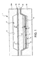
- a mold 1 intended for the manufacture of parts 2 comprising at least one internal cavity 4, and preferably one alone.
- the mold 1 uses techniques known diffusion welding and forming superplastic. Indeed, the mold 1 allows the setting work of a parts manufacturing process aimed at perform a diffusion welding step of at least two metal sheets 14, a deformation step of an assembly formed by at least two metal sheets 14 welded together, and finally an inflation step by superplastic forming of at least one cavity internal 4 of a deformed assembly comprising at least two metal sheets 14 welded together.
- the mold 1 comprises at least a part primary hollow 6 and at least part hollow secondary 8.
- the mold 1 comprises a single primary hollow part 6 and only one hollow part secondary 8.
- the hollowed out part primary 6 has two surfaces 10.12 located opposite each other.
- a first surface 10 which is planar, the flatness of this first surface 10 being necessary to perform diffusion welding of sheets 14, positioned flat and resting on this first surface 10.
- the metal sheets 14 are preferably two in number.
- the primary hollowed out part 6 comprises also a second surface 12.
- This second surface 12 may include convex portions and / or concave portions, the goal being that this second surface 12 has a geometry substantially similar to a geometry that we want to apply by deformation to an assembly comprising sheets 14 welded together, before submitting this assembly to an inflation operation by forming superplastic.
- the secondary hollowed out part 8 is, as for it, capable of receiving a deformed set of sheets 14 welded together.
- This hollowed out part secondary 8 includes an internal wall 16 of geometry substantially identical to final external geometry of a part 2 to be produced. So during an operation inflation by superplastic forming of an assembly deformed metal sheets 14 welded together, this set deforms until it marries the wall internal 16 of the secondary hollow part 8, so to adopt a final external form corresponding to the form of a part 2 that one wishes to produce.
- the mold 1 is also in cooperation with different elements which allow to carry out the various operations mentioned above.
- the mold is subjected to a heating operation including temperature applied is about 920 ° C.
- This temperature can of course be modified by the skilled person, according to his appreciation of criteria such as the volume of the mold 1 or the exact composition of the materials constituting the metal sheets 14.
- mold 1 is also connected to various means for injecting gas under pressure (not shown).
- mold 1 is likely to undergo a first injection of pressurized gas at inside its primary hollowed out part 6, in order to press the metal sheets 14, positioned one on the other on the others, against the first flat surface 10 of the primary hollowed out part 6 (as shown by the arrow A in Figure 1).
- a diffusion welding of metal sheets 14 east then realized.
- the mold 1 is again susceptible to injection of gas under pressure, always at inside this primary hollowed out part 6.
- the gas resulting from the first injection of pressurized gas is purged to make way for gas from a second injection gas under pressure.
- This action results in to press and deform the assembly formed by the metal sheets 14 welded together, to give this set a shape substantially identical to a shape of the second surface 12.
- the arrow B of the figure 2 symbolizes the plating of metal sheets 14 against the second surface 12.
- a third gas injection can be performed to perform, using the heat applied, a inflation by superplastic forming. Inflation by superplastic forming then allows to develop the internal cavity 4 inside the hollowed out part secondary 8. Thanks to this third injection, the deformed assembly of welded metal sheets 14 between them, adopts a corresponding external geometry substantially to the geometry of the internal wall 16 of the secondary hollow part 8.
- the metal sheets 14 can then marry the inner wall 16 of the part hollowed out secondary 8, and give the whole a form external corresponding to the external shape of a part 2 that we want to achieve.
- the arrows C visible on Figures 1 and 2 symbolize the plating of the sheets metallic 14 on the inner wall 16 of the part secondary hollow 8.
- an inert gas preferably a gas of the argon type.
- the mold 1 includes a block 18 separating the parts primary 6 and secondary 8.
- this block 18 includes one of the first 10 and second surfaces 12 of the hollowed out part primary 6, and also partially includes the internal wall 16 of the secondary hollow part 8.
- this block 18, being an integral part of mold 1 has two surfaces, each of which is used to at least partially constitute the primary 6 and secondary 8 hollowed out parts.
- the mold 1 comprises a block upper 20a, an intermediate block 18 as well as a lower block 22. These three blocks are superimposed on top of each other, thus defining the hollowed out part primary 6 as well as the secondary hollowed out part 8.
- This configuration of mold 1 is particularly interesting because of the simplicity of the design, but also because of the simplicity it offers when handling this mold 1. From more, when the three blocks 18, 20a, 22 of the mold 1 are united with each other, in order to undergo a heating operation, the different pressurized gas injections put the primary and secondary hollowed out parts 6.8 in equipression, which greatly reduces the bending stresses on the intermediate block 18. The direct consequence of such a balancing on the part and else of the intermediate block 18 is therefore the possibility of reducing the latter, causing by consequently a reduction in mold costs 1.
- first flat surface 10 is located on the intermediate block 18 (FIG. 2), or that this first flat surface 10 is located on the block upper 20b ( Figure 3).
- the invention also relates to a method for manufacturing parts 2 comprising at least one internal cavity 4.
- the process must operate three separate steps to lead to a final piece 2. Among these steps, has a diffusion welding step of at least two metal sheets 14, a deformation step of an assembly comprising at least two sheets 14 welded together, and finally a step inflation by superplastic forming of at least one internal cavity 4 of a deformed assembly of at least two metal sheets 14 welded together.
- a mold 1 by subjecting it to a single operation of heating, preferably at a temperature about 920 ° C.
- the method according to the invention is able to process several parts 2a, 2b at the same time time, subjecting them to different stages according to the hollow part of the mold 1 in which they are found.
- the method treats simultaneously two parts 2a, 2b.
- first part 2a as well than a second part 2b, the first part 2a undergoing successive diffusion welding operations and deformation in a primary hollow part 6, then that the second part 2b undergoes during the same charging, an inflation operation by forming superplastic in a secondary hollow part 8.
- This process is particularly interesting in the production of hollow parts used in the aeronautical industry.
Landscapes
- Engineering & Computer Science (AREA)
- Mechanical Engineering (AREA)
- Physics & Mathematics (AREA)
- Fluid Mechanics (AREA)
- Shaping Metal By Deep-Drawing, Or The Like (AREA)
- Pressure Welding/Diffusion-Bonding (AREA)
- Mounting, Exchange, And Manufacturing Of Dies (AREA)
- Medicines Containing Antibodies Or Antigens For Use As Internal Diagnostic Agents (AREA)
- Medicines That Contain Protein Lipid Enzymes And Other Medicines (AREA)
- Forging (AREA)
Abstract
Description
- la figure 1 représente une vue schématique d'un moule selon un mode préféré de réalisation de l'invention, lorsque ce moule reçoit d'une part des tôles métalliques subissant un soudage par diffusion, et d'autre part un ensemble déformé de tôles métalliques soudées entre elles subissant un gonflage par formage superplastique.
- la figure 2 représente une vue schématique d'un moule utilisé pour mettre en oeuvre un procédé selon un mode préféré de réalisation de l'invention, lorsque l'opération de mise en chauffe de ce moule est achevée.
- la figure 3 représente une vue schématique d'un moule selon un autre mode préféré de réalisation de l'invention, lorsque ce moule reçoit d'une part des tôles métalliques subissant un soudage par diffusion, et d'autre part un ensemble déformé de tôles métalliques soudées entre elles subissant un gonflage par formage superplastique.
Claims (11)
- Procédé de fabrication de pièces (2) comprenant au moins une cavité interne (4), ledit procédé comprenant successivement une étape de soudage par diffusion d'au moins deux tôles métalliques (14), une étape de déformation d'un ensemble formé par lesdites tôles métalliques (14) soudées entre elles, ainsi qu'une étape de gonflage de chacune des cavités internes (4) par formage superplastique, caractérisé en ce que le procédé est réalisé en utilisant un moule (1) permettant, lors d'une unique opération de mise en chauffe de ce moule (1), de réaliser successivement l'étape de soudage par diffusion et l'étape de déformation sur au moins une première pièce (2a) se situant dans une partie évidée primaire (6) du moule (1), ainsi que de réaliser l'étape de gonflage par formage superplastique sur au moins une seconde pièce (2b) se situant dans une partie évidée secondaire (8) du moule (1).
- Procédé de fabrication selon la revendication 1, caractérisé en ce que pour chaque première pièce (2a), l'étape de soudage par diffusion est réalisée en effectuant à l'intérieur de la partie évidée primaire (6) du moule (1), une première injection de gaz sous pression plaquant lesdites tôles métalliques (14) contre une première surface (10) plane de la partie évidée primaire (6) du moule (1).
- Procédé de fabrication selon la revendication 2, caractérisé en ce que pour chaque première pièce (2a), l'étape de déformation de l'ensemble formé par lesdites tôles métalliques (14) soudées entre elles est réalisée en purgeant ledit gaz sous pression introduit dans la partie évidée primaire (6) lors de ladite première injection de gaz, puis en effectuant une seconde injection de gaz sous pression plaquant lesdites tôles métalliques (14) soudées entre elles contre une seconde surface (12) de la partie évidée primaire (6) du moule (1).
- Procédé de fabrication selon l'une quelconque des revendications précédentes, caractérisé en ce que pour chaque seconde pièce (2b), l'étape de gonflage de chacune des cavités internes (4) par formage superplastique est réalisée en effectuant une troisième injection de gaz sous pression dans chacune des cavités internes (4), le gonflage étant réalisé de sorte qu'un ensemble déformé d'au moins deux tôles métalliques (14) soudées entre elles épouse une paroi interne (16) de la partie évidée secondaire (8) du moule (1).
- Procédé de fabrication selon l'une quelconque des revendications précédentes, caractérisé en ce que l'unique opération de mise en chauffe du moule (1) s'effectue à une température d'environ 920°C.
- Moule (1) destiné à la fabrication de pièces (2a,2b) comprenant au moins une cavité interne (4), caractérisé en ce qu'il comprend au moins une partie évidée primaire (6) ainsi qu'au moins une partie évidée secondaire (8), chaque partie évidée primaire (6) comprenant une première surface (10) ainsi qu'une seconde surface (12), ladite première surface (10) étant plane afin de permettre un soudage par diffusion d'au moins deux tôles métalliques (14) lorsque celles-ci sont plaquées contre cette première surface (10), ladite seconde surface (12) permettant une déformation de l'ensemble formé par lesdites tôles métalliques (14) soudées entre elles lorsque ledit ensemble est plaqué contre cette seconde surface (12), chaque partie évidée secondaire (8) du moule (1) étant apte à recevoir un ensemble déformé de tôles métalliques (14) soudées entre elles et subissant un gonflage par formage superplastique, ladite partie évidée secondaire (8) comprenant une paroi interne (16) de géométrie sensiblement identique à une géométrie externe finale d'une pièce (2) à réaliser.
- Moule (1) selon la revendication 6, caractérisé en ce qu'il comprend au moins un bloc (18) comprenant une desdites première (10) et seconde surfaces (12) d'une partie évidée primaire (6), et en ce que ce bloc (18) comprend également partiellement une paroi interne (16) d'une partie évidée secondaire (8).
- Moule (1) selon la revendication 6 ou la revendication 7, caractérisé en ce qu'il comprend une partie évidée primaire (6) ainsi qu'une partie évidée secondaire (8), lesdites première (6) et seconde parties évidées (8) étant définies par un bloc supérieur (20a,20b), un bloc intermédiaire (18) et un bloc inférieur (22), ces blocs (18,20a,20b,22) étant arrangés les uns sur les autres.
- Moule (1) selon la revendication 8, caractérisé en ce que la partie évidée primaire (6) se situe au-dessus de la partie évidée secondaire (8).
- Moule (1) selon la revendication 9, caractérisé en ce que ladite première surface (10) de la partie évidée primaire (6) se situe sur ledit bloc supérieur (20b).
- Moule (1) selon la revendication 9, caractérisé en ce que ladite première surface (10) de la partie évidée primaire (6) se situe sur ledit bloc intermédiaire (18).
Applications Claiming Priority (2)
| Application Number | Priority Date | Filing Date | Title |
|---|---|---|---|
| FR0200235A FR2834481B1 (fr) | 2002-01-10 | 2002-01-10 | Procede de fabrication de pieces par soudage par diffusion et par formage superplastique, et moule pour mettre en oeuvre un tel procede |
| FR0200235 | 2002-01-10 |
Publications (2)
| Publication Number | Publication Date |
|---|---|
| EP1332828A1 true EP1332828A1 (fr) | 2003-08-06 |
| EP1332828B1 EP1332828B1 (fr) | 2010-11-03 |
Family
ID=8871216
Family Applications (1)
| Application Number | Title | Priority Date | Filing Date |
|---|---|---|---|
| EP03290054A Expired - Lifetime EP1332828B1 (fr) | 2002-01-10 | 2003-01-10 | Procédé de fabrication de pièces par soudage par diffusion et par formage superplastique, et moule pour mettre en oeuvre un tel procédé |
Country Status (8)
| Country | Link |
|---|---|
| US (1) | US7441691B2 (fr) |
| EP (1) | EP1332828B1 (fr) |
| AT (1) | ATE486683T1 (fr) |
| CA (1) | CA2475024C (fr) |
| DE (1) | DE60334750D1 (fr) |
| ES (1) | ES2355350T3 (fr) |
| FR (1) | FR2834481B1 (fr) |
| WO (1) | WO2003057397A1 (fr) |
Cited By (3)
| Publication number | Priority date | Publication date | Assignee | Title |
|---|---|---|---|---|
| WO2006047066A1 (fr) * | 2004-10-21 | 2006-05-04 | The Boeing Company | Ensemble structurel forme et preforme et procede associes |
| EP1728580A1 (fr) * | 2005-06-01 | 2006-12-06 | Fuji Jukogyo Kabushiki Kaisha | Procédé de formation d' un panneau superplastique lié par diffusion |
| RU236674U1 (ru) * | 2025-03-17 | 2025-08-18 | Федеральное государственное бюджетное образовательное учреждение высшего образования "Саратовский государственный технический университет имени Гагарина Ю.А." | Устройство для диффузионной сварки |
Families Citing this family (12)
| Publication number | Priority date | Publication date | Assignee | Title |
|---|---|---|---|---|
| FR2867096B1 (fr) | 2004-03-08 | 2007-04-20 | Snecma Moteurs | Procede de fabrication d'un bord d'attaque ou de fuite de renforcement pour une aube de soufflante |
| GB0412915D0 (en) * | 2004-06-10 | 2004-07-14 | Rolls Royce Plc | Method of making and joining an aerofoil and root |
| CN103201601A (zh) * | 2010-10-29 | 2013-07-10 | 株式会社威工 | 容器 |
| RU2525963C2 (ru) * | 2012-12-25 | 2014-08-20 | Александр Яковлевич Зоркин | Устройство для диффузионной сварки |
| RU2525968C2 (ru) * | 2012-12-25 | 2014-08-20 | Александр Яковлевич Зоркин | Устройство для диффузионной сварки |
| WO2015053955A1 (fr) * | 2013-10-09 | 2015-04-16 | United Technologies Corporation | Procédé et système pour éléments liés par diffusion ayant des passages internes |
| CN103753119A (zh) * | 2013-12-09 | 2014-04-30 | 北京航星机器制造有限公司 | 一种轻量化壁板超塑成形制造方法 |
| ES2947758T3 (es) | 2017-08-22 | 2023-08-18 | Bae Systems Plc | Procedimiento de conformación superplástica y unión por difusión |
| US10821541B2 (en) * | 2017-08-22 | 2020-11-03 | Bae Systems Plc | Superplastic forming and diffusion bonding process |
| RU189573U1 (ru) * | 2018-06-13 | 2019-05-28 | Федеральное государственное бюджетное образовательное учреждение высшего образования "Саратовский государственный технический университет имени Гагарина Ю.А." (СГТУ имени Гагарина Ю.А.) | Мобильный модуль для диффузионной сварки |
| CN111037086B (zh) * | 2019-12-19 | 2020-11-10 | 中国航空制造技术研究院 | 包套组坯密封装置及密封方法、包套成型设备及加工方法 |
| CN112051381B (zh) * | 2020-08-26 | 2022-11-29 | 中国航空制造技术研究院 | 一种材料性能的测试方法及测试工装 |
Citations (3)
| Publication number | Priority date | Publication date | Assignee | Title |
|---|---|---|---|---|
| US3927817A (en) * | 1974-10-03 | 1975-12-23 | Rockwell International Corp | Method for making metallic sandwich structures |
| US5683608A (en) * | 1991-04-05 | 1997-11-04 | The Boeing Company | Ceramic die for induction heating work cells |
| US5797239A (en) * | 1995-03-28 | 1998-08-25 | Mcdonnell Douglas Corporation | Titanium reinforced structural panel having a predetermined shape |
-
2002
- 2002-01-10 FR FR0200235A patent/FR2834481B1/fr not_active Expired - Lifetime
-
2003
- 2003-01-10 ES ES03290054T patent/ES2355350T3/es not_active Expired - Lifetime
- 2003-01-10 EP EP03290054A patent/EP1332828B1/fr not_active Expired - Lifetime
- 2003-01-10 WO PCT/FR2003/000061 patent/WO2003057397A1/fr not_active Ceased
- 2003-01-10 DE DE60334750T patent/DE60334750D1/de not_active Expired - Lifetime
- 2003-01-10 US US10/504,638 patent/US7441691B2/en not_active Expired - Lifetime
- 2003-01-10 AT AT03290054T patent/ATE486683T1/de not_active IP Right Cessation
- 2003-01-10 CA CA2475024A patent/CA2475024C/fr not_active Expired - Lifetime
Patent Citations (3)
| Publication number | Priority date | Publication date | Assignee | Title |
|---|---|---|---|---|
| US3927817A (en) * | 1974-10-03 | 1975-12-23 | Rockwell International Corp | Method for making metallic sandwich structures |
| US5683608A (en) * | 1991-04-05 | 1997-11-04 | The Boeing Company | Ceramic die for induction heating work cells |
| US5797239A (en) * | 1995-03-28 | 1998-08-25 | Mcdonnell Douglas Corporation | Titanium reinforced structural panel having a predetermined shape |
Cited By (6)
| Publication number | Priority date | Publication date | Assignee | Title |
|---|---|---|---|---|
| WO2006047066A1 (fr) * | 2004-10-21 | 2006-05-04 | The Boeing Company | Ensemble structurel forme et preforme et procede associes |
| US7210611B2 (en) | 2004-10-21 | 2007-05-01 | The Boeing Company | Formed structural assembly and associated preform and method |
| US7967240B2 (en) | 2004-10-21 | 2011-06-28 | The Boeing Company | Formed structural assembly and associated preform and method |
| US8329312B2 (en) | 2004-10-21 | 2012-12-11 | The Boeing Company | Formed structural assembly and associated preform |
| EP1728580A1 (fr) * | 2005-06-01 | 2006-12-06 | Fuji Jukogyo Kabushiki Kaisha | Procédé de formation d' un panneau superplastique lié par diffusion |
| RU236674U1 (ru) * | 2025-03-17 | 2025-08-18 | Федеральное государственное бюджетное образовательное учреждение высшего образования "Саратовский государственный технический университет имени Гагарина Ю.А." | Устройство для диффузионной сварки |
Also Published As
| Publication number | Publication date |
|---|---|
| US7441691B2 (en) | 2008-10-28 |
| CA2475024A1 (fr) | 2003-07-17 |
| FR2834481B1 (fr) | 2004-02-27 |
| EP1332828B1 (fr) | 2010-11-03 |
| ES2355350T3 (es) | 2011-03-25 |
| CA2475024C (fr) | 2010-06-29 |
| US20050121498A1 (en) | 2005-06-09 |
| FR2834481A1 (fr) | 2003-07-11 |
| WO2003057397A1 (fr) | 2003-07-17 |
| ATE486683T1 (de) | 2010-11-15 |
| DE60334750D1 (de) | 2010-12-16 |
Similar Documents
| Publication | Publication Date | Title |
|---|---|---|
| EP1332828B1 (fr) | Procédé de fabrication de pièces par soudage par diffusion et par formage superplastique, et moule pour mettre en oeuvre un tel procédé | |
| EP2507010A1 (fr) | Procede de realisation d' un renfort metallique d' aube de turbomachine | |
| EP0836899B1 (fr) | Procédé de fabrication d'une aube creuse de turbomachine | |
| FR2944721A1 (fr) | Procede de fabrication d'un aubage par moulage par injection de poudre metallique | |
| FR2682904A1 (fr) | Procede de fabrication d'un article, procede de soudage par diffusion, et chambre a vide. | |
| EP1171272B1 (fr) | Outillage de mise en forme pour la polymerisation de pieces profilees en materiau composite | |
| FR3086567A1 (fr) | Procede de realisation de contreforme et procede de fabrication de piece de forme complexe utilisant une telle contre-forme | |
| JPH0647569A (ja) | 中空物品を製造する方法 | |
| FR2874339A1 (fr) | Procede de fabrication de pieces constitutives d'une aube creuse par forage sur presse | |
| WO2021123456A1 (fr) | Procédé et outillage pour la fabrication d'une coque quadrangulaire en matériau composite | |
| EP1459818B1 (fr) | Ensemble permettant la fabrication d'une pièce mécanique creuse par soudage-diffusion et formage superplastique, utilisation d'un tel ensemble et procédé de fabrication d'une telle pièce mécanique | |
| EP3812087B1 (fr) | Procédé de fabrication de pièces métalliques de formes complexes par soudage-diffusion | |
| FR2487233A1 (fr) | Procede de fabrication de douilles de cartouches et douilles de cartouches obtenues par ce procede | |
| EP2682257A1 (fr) | Procédé et dispositif de fabrication de pièces en matériau composite par RTM | |
| EP0018255B1 (fr) | Procédé pour le formage d'une matière superplastique | |
| EP1071526B1 (fr) | Procede de fabrication de piece tubulaire metallique et d'arbre tubulaire composite | |
| FR2981001A1 (fr) | Procede de fabrication en materiau composite de pieces tridimensionnelles et/ou massives | |
| FR3138689A1 (fr) | Procédé de fabrication de canalisations pour un échangeur de chaleur | |
| EP0803301A1 (fr) | Procédé et outillage de fabrication d'une pièce monobloc par les techniques de formage superplastique et de soudage par diffusion | |
| WO2022043373A1 (fr) | Procédé de mise en forme d'une pièce tubulaire comportant une cavité | |
| FR2619034A1 (fr) | Procede pour fabriquer par compression d'une poudre un element de construction comportant des parties avec des parois d'epaisseurs fortement differentes | |
| FR2848496A1 (fr) | Procede de fabrication d'une piece creuse en matiere plastique, equipement mettant en oeuvre ce procede et piece obtenue par ce procede | |
| EP3774303B1 (fr) | Outillage pour la mise en oeuvre d'un procédé de frittage flash d'une poudre d'origine naturelle | |
| EP0203866A1 (fr) | Filière pour filage à chaud | |
| EP0031277A1 (fr) | Procédé de fabrication de bagues polymétalliques par déformation de gorges et bagues polymétalliques |
Legal Events
| Date | Code | Title | Description |
|---|---|---|---|
| PUAI | Public reference made under article 153(3) epc to a published international application that has entered the european phase |
Free format text: ORIGINAL CODE: 0009012 |
|
| 17P | Request for examination filed |
Effective date: 20030117 |
|
| AK | Designated contracting states |
Designated state(s): AT BE BG CH CY CZ DE DK EE ES FI FR GB GR HU IE IT LI LU MC NL PT SE SI SK TR |
|
| AX | Request for extension of the european patent |
Extension state: AL LT LV MK RO |
|
| AKX | Designation fees paid |
Designated state(s): AT BE BG CH CY CZ DE DK EE ES FI FR GB GR HU IE IT LI LU MC NL PT SE SI SK TR |
|
| RAP1 | Party data changed (applicant data changed or rights of an application transferred) |
Owner name: SNECMA Owner name: HUREL-HISPANO LE HAVRE |
|
| GRAP | Despatch of communication of intention to grant a patent |
Free format text: ORIGINAL CODE: EPIDOSNIGR1 |
|
| GRAS | Grant fee paid |
Free format text: ORIGINAL CODE: EPIDOSNIGR3 |
|
| GRAA | (expected) grant |
Free format text: ORIGINAL CODE: 0009210 |
|
| AK | Designated contracting states |
Kind code of ref document: B1 Designated state(s): AT BE BG CH CY CZ DE DK EE ES FI FR GB GR HU IE IT LI LU MC NL PT SE SI SK TR |
|
| REG | Reference to a national code |
Ref country code: GB Ref legal event code: FG4D Free format text: NOT ENGLISH |
|
| REG | Reference to a national code |
Ref country code: CH Ref legal event code: EP |
|
| REG | Reference to a national code |
Ref country code: IE Ref legal event code: FG4D Free format text: LANGUAGE OF EP DOCUMENT: FRENCH |
|
| REF | Corresponds to: |
Ref document number: 60334750 Country of ref document: DE Date of ref document: 20101216 Kind code of ref document: P |
|
| REG | Reference to a national code |
Ref country code: SE Ref legal event code: TRGR |
|
| REG | Reference to a national code |
Ref country code: NL Ref legal event code: VDEP Effective date: 20101103 |
|
| REG | Reference to a national code |
Ref country code: ES Ref legal event code: FG2A Ref document number: 2355350 Country of ref document: ES Kind code of ref document: T3 Effective date: 20110325 |
|
| REG | Reference to a national code |
Ref country code: IE Ref legal event code: FD4D |
|
| PG25 | Lapsed in a contracting state [announced via postgrant information from national office to epo] |
Ref country code: SI Free format text: LAPSE BECAUSE OF FAILURE TO SUBMIT A TRANSLATION OF THE DESCRIPTION OR TO PAY THE FEE WITHIN THE PRESCRIBED TIME-LIMIT Effective date: 20101103 Ref country code: PT Free format text: LAPSE BECAUSE OF FAILURE TO SUBMIT A TRANSLATION OF THE DESCRIPTION OR TO PAY THE FEE WITHIN THE PRESCRIBED TIME-LIMIT Effective date: 20110303 Ref country code: AT Free format text: LAPSE BECAUSE OF FAILURE TO SUBMIT A TRANSLATION OF THE DESCRIPTION OR TO PAY THE FEE WITHIN THE PRESCRIBED TIME-LIMIT Effective date: 20101103 Ref country code: NL Free format text: LAPSE BECAUSE OF FAILURE TO SUBMIT A TRANSLATION OF THE DESCRIPTION OR TO PAY THE FEE WITHIN THE PRESCRIBED TIME-LIMIT Effective date: 20101103 Ref country code: FI Free format text: LAPSE BECAUSE OF FAILURE TO SUBMIT A TRANSLATION OF THE DESCRIPTION OR TO PAY THE FEE WITHIN THE PRESCRIBED TIME-LIMIT Effective date: 20101103 Ref country code: BG Free format text: LAPSE BECAUSE OF FAILURE TO SUBMIT A TRANSLATION OF THE DESCRIPTION OR TO PAY THE FEE WITHIN THE PRESCRIBED TIME-LIMIT Effective date: 20110203 |
|
| PG25 | Lapsed in a contracting state [announced via postgrant information from national office to epo] |
Ref country code: GR Free format text: LAPSE BECAUSE OF FAILURE TO SUBMIT A TRANSLATION OF THE DESCRIPTION OR TO PAY THE FEE WITHIN THE PRESCRIBED TIME-LIMIT Effective date: 20110204 |
|
| PG25 | Lapsed in a contracting state [announced via postgrant information from national office to epo] |
Ref country code: IE Free format text: LAPSE BECAUSE OF FAILURE TO SUBMIT A TRANSLATION OF THE DESCRIPTION OR TO PAY THE FEE WITHIN THE PRESCRIBED TIME-LIMIT Effective date: 20101103 Ref country code: CZ Free format text: LAPSE BECAUSE OF FAILURE TO SUBMIT A TRANSLATION OF THE DESCRIPTION OR TO PAY THE FEE WITHIN THE PRESCRIBED TIME-LIMIT Effective date: 20101103 Ref country code: EE Free format text: LAPSE BECAUSE OF FAILURE TO SUBMIT A TRANSLATION OF THE DESCRIPTION OR TO PAY THE FEE WITHIN THE PRESCRIBED TIME-LIMIT Effective date: 20101103 |
|
| BERE | Be: lapsed |
Owner name: SNECMA Effective date: 20110131 Owner name: HUREL-HISPANO LE HAVRE Effective date: 20110131 |
|
| PG25 | Lapsed in a contracting state [announced via postgrant information from national office to epo] |
Ref country code: SK Free format text: LAPSE BECAUSE OF FAILURE TO SUBMIT A TRANSLATION OF THE DESCRIPTION OR TO PAY THE FEE WITHIN THE PRESCRIBED TIME-LIMIT Effective date: 20101103 Ref country code: DK Free format text: LAPSE BECAUSE OF FAILURE TO SUBMIT A TRANSLATION OF THE DESCRIPTION OR TO PAY THE FEE WITHIN THE PRESCRIBED TIME-LIMIT Effective date: 20101103 Ref country code: MC Free format text: LAPSE BECAUSE OF NON-PAYMENT OF DUE FEES Effective date: 20110131 |
|
| REG | Reference to a national code |
Ref country code: CH Ref legal event code: PL |
|
| PLBE | No opposition filed within time limit |
Free format text: ORIGINAL CODE: 0009261 |
|
| STAA | Information on the status of an ep patent application or granted ep patent |
Free format text: STATUS: NO OPPOSITION FILED WITHIN TIME LIMIT |
|
| 26N | No opposition filed |
Effective date: 20110804 |
|
| PG25 | Lapsed in a contracting state [announced via postgrant information from national office to epo] |
Ref country code: CH Free format text: LAPSE BECAUSE OF NON-PAYMENT OF DUE FEES Effective date: 20110131 Ref country code: LI Free format text: LAPSE BECAUSE OF NON-PAYMENT OF DUE FEES Effective date: 20110131 |
|
| PG25 | Lapsed in a contracting state [announced via postgrant information from national office to epo] |
Ref country code: BE Free format text: LAPSE BECAUSE OF NON-PAYMENT OF DUE FEES Effective date: 20110131 |
|
| REG | Reference to a national code |
Ref country code: DE Ref legal event code: R097 Ref document number: 60334750 Country of ref document: DE Effective date: 20110804 |
|
| PG25 | Lapsed in a contracting state [announced via postgrant information from national office to epo] |
Ref country code: CY Free format text: LAPSE BECAUSE OF FAILURE TO SUBMIT A TRANSLATION OF THE DESCRIPTION OR TO PAY THE FEE WITHIN THE PRESCRIBED TIME-LIMIT Effective date: 20101103 Ref country code: LU Free format text: LAPSE BECAUSE OF NON-PAYMENT OF DUE FEES Effective date: 20110110 |
|
| PG25 | Lapsed in a contracting state [announced via postgrant information from national office to epo] |
Ref country code: TR Free format text: LAPSE BECAUSE OF FAILURE TO SUBMIT A TRANSLATION OF THE DESCRIPTION OR TO PAY THE FEE WITHIN THE PRESCRIBED TIME-LIMIT Effective date: 20101103 |
|
| PG25 | Lapsed in a contracting state [announced via postgrant information from national office to epo] |
Ref country code: HU Free format text: LAPSE BECAUSE OF FAILURE TO SUBMIT A TRANSLATION OF THE DESCRIPTION OR TO PAY THE FEE WITHIN THE PRESCRIBED TIME-LIMIT Effective date: 20101103 |
|
| REG | Reference to a national code |
Ref country code: FR Ref legal event code: PLFP Year of fee payment: 14 |
|
| REG | Reference to a national code |
Ref country code: FR Ref legal event code: PLFP Year of fee payment: 15 |
|
| REG | Reference to a national code |
Ref country code: FR Ref legal event code: PLFP Year of fee payment: 16 |
|
| REG | Reference to a national code |
Ref country code: FR Ref legal event code: CD Owner name: HUREL-HISPANO LE HAVRE, FR Effective date: 20170719 Ref country code: FR Ref legal event code: CD Owner name: SAFRAN AIRCRAFT ENGINES, FR Effective date: 20170719 |
|
| PGFP | Annual fee paid to national office [announced via postgrant information from national office to epo] |
Ref country code: GB Payment date: 20211216 Year of fee payment: 20 Ref country code: FR Payment date: 20211215 Year of fee payment: 20 Ref country code: SE Payment date: 20211216 Year of fee payment: 20 |
|
| PGFP | Annual fee paid to national office [announced via postgrant information from national office to epo] |
Ref country code: DE Payment date: 20211215 Year of fee payment: 20 |
|
| PGFP | Annual fee paid to national office [announced via postgrant information from national office to epo] |
Ref country code: IT Payment date: 20220103 Year of fee payment: 20 Ref country code: ES Payment date: 20220201 Year of fee payment: 20 |
|
| REG | Reference to a national code |
Ref country code: DE Ref legal event code: R071 Ref document number: 60334750 Country of ref document: DE |
|
| REG | Reference to a national code |
Ref country code: GB Ref legal event code: PE20 Expiry date: 20230109 |
|
| REG | Reference to a national code |
Ref country code: SE Ref legal event code: EUG |
|
| REG | Reference to a national code |
Ref country code: ES Ref legal event code: FD2A Effective date: 20230426 |
|
| PG25 | Lapsed in a contracting state [announced via postgrant information from national office to epo] |
Ref country code: GB Free format text: LAPSE BECAUSE OF EXPIRATION OF PROTECTION Effective date: 20230109 |
|
| PG25 | Lapsed in a contracting state [announced via postgrant information from national office to epo] |
Ref country code: ES Free format text: LAPSE BECAUSE OF EXPIRATION OF PROTECTION Effective date: 20230111 |