Technical Field
The present invention relates to a tooth surface finish
machining method after forming a gear.
Background Art
In an automobile or various kinds of mechanical devices,
a large kinds of and a large number of gears are assembled. In
manufacturing these gears, teeth are formed by molding material
such as carbon steel or alloy steel and, thereafter, a finish
machining of tooth surface is performed to enhance a shape and
the smoothness of the tooth surface.
As conventional tooth-surface finish machining methods,
a shaving machining method which uses a shaving cutter, a polish
finishing method which uses abrasive grains such as gear grinding,
honing, super precision finishing, lapping, polishing, a
chemical polishing method which uses a chemical attack liquid
and the like have been known. Further, various methods which
combine the above-mentioned respective methods and other methods
also have been proposed.
Japanese Laid-open Patent Publication 101328/1999
discloses a method in which a gear which is preliminarily provided
with a carburized abnormal layer (oxidized layer) and a shaving
finish gear are served in actual use in a meshed form and the
tooth surfaces of both gears are naturally worn and are finished
in an initial stage of the operation.
Japanese Laid-open Patent Publication 193118/1989
discloses a method in which a master gear for finish machining
is meshed with a gear to be machined and these gears are rotated
together and rotary shafts of these gears are reciprocated in
parallel so as to finish tooth surfaces of the gear to be machined
by positively making the tooth surfaces wear.
Japanese Laid-open Patent Publication 318209/1989
discloses a method in which a plurality of gears to be machined
are arranged on a rotary shaft in the same manner as in actual
use and toothed tools are respectively arranged to correspond
with these gears to be machined and the toothed tools are
reciprocated and rotated such that a slipping is generated in
the tooth trace direction so as to achieve the polish finishing.
Japanese Laid-open Patent Publication 100316/1986
discloses a surface finishing method which performs an
electrolytic machining by polishing the surface of a work to
be machined.
Japanese Laid-open Patent Publication 7221/1988
discloses a method which performs a chemical polishing before
a final surface treatment.
However, the above-mentioned conventional tooth-surface
finish machining method has following drawbacks.
That is, in performing the tooth-surface finish machining
of each gear, a slight displacement is generated in meshing in
actual use so that the improvement in terms of vibration and
noises is small. Further, in the method (Japanese Laid-open
Patent Publication 101328/1999) which positively generates the
wear on the tooth surface in the initial stage of the operation,
it is difficult to suppress the generation of the vibration and
noises at the time of the initial operation. Further, the
above-mentioned other conventional techniques have not always
achieved the sufficient vibration and noise suppression effect
when they are served actual operation.
The present invention has been made in view of the
above-mentioned conventional drawbacks and it is an object of
the present invention to provide a gear, a tooth-surface finish
machining method and a tooth-surface finish machining device
which exhibits the sufficient silence by reducing the generation
of vibration and noises in actual use.
Disclosure of the Invention
According to a first aspect of the present invention, in
a method for performing a finish machining of a tooth surface
of a gear to be machined, in a state that at least one counter
gear is meshed with the above-mentioned gear to be machined,
both gears are rotated while supplying water or an aqueous
solution containing no abrasive grains to meshing portions of
these gears thus obtaining a surface with a small surface
roughness on the above-mentioned tooth surface of the
above-mentioned gear to be machined.
The gist which should be noted most is, as described above,
that both gears are rotated while supplying water or the aqueous
solution to the meshing portions of the gear to be machined and
the counter gear and the above-mentioned water or aqueous
solution does not contain abrasive grains at all. Here, the
supply of the above-mentioned water or aqueous solution is
performed not only in the liquefied state but also in the gaseous
state.
Any types of gears including a spur gear are applicable
as the above-mentioned gear to be machined. Further, as the
material of the gear to be machined, various kinds of materials
such as ceramic are applicable besides metal material including
carbon steel and alloy steel.
Subsequently, the manner of operation and advantageous
effects are explained.
In the above-mentioned tooth-surface finish machining
method, as mentioned above, at least one counter gear which can
be meshed with the gear to be machined is prepared. Then, in
the state that the counter gear is meshed with the gear to be
machined, both gears are rotated while supplying water or the
aqueous solution containing no abrasive grains to the meshing
portions of both gears. Accordingly, compared to a case in which
a conventional finish machining method is performed, the finish
machining method of the present invention can obtain the
remarkably excellent tooth surfaces of the gear to be machined.
Further, the gear which is obtained by the method exhibits the
smaller vibration and noises in actual use compared to the
conventional gears thus realizing a gear which exhibits the
sufficient silence.
The reason is as follows.
That is, by supplying the above-mentioned water or aqueous
solution to the portion where the above-mentioned counter gear
is meshed with the above-mentioned gear to be machined, the tooth
surface of the gear to be machined is exposed to an atmosphere
in which the tooth surface is more liable to be oxidized than
in a case in which the tooth surface is exposed to air. Further,
by rotating the gear to be machined and the counter gear, the
tooth surfaces of the counter gear are sequentially brought into
contact with each tooth surfaces of the gear to be machined the
tooth surface and the sliding movement or the rolling movement
is repeated.
Then, in the atmosphere in which the tooth surface of the
gear to be machined is more liable to be oxidized than in the
case in which the tooth surface is exposed to air, by applying
the energy generated by the above-mentioned sliding movement
or the rolling movement to the tooth surface of the gear to be
machined, the oxidation of the surface of the tooth surface is
accelerated and an oxide is removed. That is, a so-called
mechano-chemical action is generated due to the sliding movement
or the rolling movement applied to the above-mentioned tooth
surface in a properly controlled manner. Accordingly, the tooth
surface of the gear to be machined is improved into a state in
which the tooth surface has the optimum shape and the optimum
surface roughness in actual use.
Further, the above-mentioned water or aqueous solution
does not contain the abrasive grains at all. Accordingly, the
smoothness of the surface is not achieved by the grinding using
the abrasive grains but by a mechanism which is comprised of
the above-mentioned acceleration of oxidation and the removal
of oxide. Therefore, on the tooth surface of the above-mentioned
gear to be machined, grinding traces or the like which are
generated when the tooth surface is ground by the abrasive grains
are hardly generated. As a result, the tooth surface of the
gear to be machined becomes a surface exhibiting an extremely
small surface roughness compared to the tooth surface of the
conventional gear to be machined.
Further, such excellent manner of operation and effect
can be effectively achieved even when the gear to be machined
is made of ceramic or other material besides metal such as carbon
steel.
Then, according to a second aspect of the present invention,
in a method for performing a finish machining of a tooth surface
of a gear to be machined and tooth surfaces of other gears to
be machined, in a state that at least one other gear to be machined
is meshed with the above-mentioned gear to be machined, both
gears are rotated while supplying water or an aqueous solution
containing no abrasive grains to meshing portions of these gears
thus obtaining a surface with a small surface roughness on the
above-mentioned respective tooth surfaces of the
above-mentioned gear to be machined and the above-mentioned other
gear to be machined.
In this case, by performing the above-mentioned finish
machining method in such a manner that a plurality of gears
to be machined are combined with each other, respective tooth
surfaces of a plurality of gears to be machined can be
simultaneously subjected to the finish machining. Accordingly,
the efficiency of the finish machining of the tooth surfaces
of the gears to be machined can be enhanced.
Further, according to a third aspect of the present
invention, with respect to a gear to which a finish machining
of a tooth surface is applied to obtain a surface with a small
surface roughness, the finish machining of the tooth surface
of the gear is performed by the finish machining method of a
tooth surface described in the first aspect of the
above-mentioned present invention.
Since the gear has the tooth surface which is
finish-machined by the above-mentioned finish-machining method,
the gear which exhibits the silence with extremely small
vibration and noises can be obtained.
Subsequently, according to a fourth aspect of the present
invention, in a device for performing the finish-machining of
a tooth surface of a gear to be machined, the device includes
a first rotary shaft which rotatably supports the above-mentioned
gear to be machined thereon, a second rotary shaft which rotatably
supports a counter gear which can be meshed with the gear to
be machined thereon, and a water supply unit which supplies water
or an aqueous solution which does not contain abrasive grains
to meshing portions between the above-mentioned gear to be
machined and the above-mentioned counter gear, wherein the
above-mentioned gear to be machined and the above-mentioned
counter gear can be rotated while supplying the above-mentioned
water and aqueous solution to the above-mentioned meshing
portions.
With the use of the device, the above-mentioned excellent
tooth-surface finish machining method can be easily performed
so that the tooth surface of the gear can be easily finished
to the excellent state.
That is, the gear to be machined and the counter gear are
mounted on the above-mentioned first rotary shaft and second
rotary shaft and are meshed with each other. Then, the
above-mentioned first rotary shaft and second rotary shaft are
rotated while supplying water or the aqueous solution to the
meshing portions from the above-mentioned water supply unit.
In this manner, the above-mentioned tooth-surface
finish-machining method can be realized.
Here, although the rotation of the above-mentioned first
rotary shaft and second rotary shaft may be performed such that
both rotary shafts are driven, it is possible to adopt a method
in which only one of the rotary shafts is driven.
Further, as the above-mentioned second rotary shafts, a
plural sets of second rotary shafts can be provided and, in this
case, a plurality of counter gears can be set.
Brief Description of the Drawings
Fig. 1 is an explanatory view showing a tooth surface finish
machining method according to an embodiment 1.
Fig. 2 is an explanatory view showing the condition of
a tooth surface after the finish-machining in the embodiment
1.
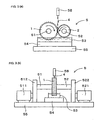
Fig. 3(a) is a front view showing the constitution of a
tooth-surface finish machining device in the embodiment 2.
Fig. 3(b) is a side view chowing the constitution of a
tooth-surface finish machining device in the embodiment 2.
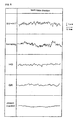
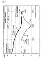
Fig. 4 is an explanatory view showing a surface roughness
measurement chart in the tooth profile direction in the
embodiment 3.
Fig. 5 is an explanatory view showing a surface roughness
measurement chart in the tooth trace direction in the embodiment
3.
Fig. 6 is an explanatory view showing the surface roughness
Rz in the embodiment 3.
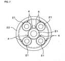
Fig. 7 is an explanatory view showing a tooth-surface
finish-machining method in a pair of planetary gears in an
embodiment 4.
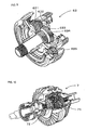
Fig. 8 is an explanatory view showing a structure of an
automatic transmission axle in an embodiment 5.
Fig. 9 is an explanatory view showing a structure of a
planetary gear couple in the embodiment 5.
Fig. 10 is an explanatory view showing a differential gear
unit in the embodiment 5.
Fig. 11 is an explanatory view showing the relationship
between the number of meshing and the vibration data in an
experiment 1 of the embodiment 6.
Fig. 12 is an explanatory view showing the relationship
between the number of meshing and the vibration data in an
experiment 2 of the embodiment 6.
Fig. 13 is an explanatory view showing the vibration data
before and after the finish machining treatment in an experiment
2 of the embodiment 6.
Fig. 14 is an explanatory view showing the relationship
between the number of meshing and the vibration data in an
experiment 3 of the embodiment 6.
Fig. 15 is an explanatory view showing the vibration data
before and after the finish machining treatment in the experiment
3 of the embodiment 6.
Fig. 16 is an explanatory view showing the relationship
between the number of meshing and the vibration data in an
experiment 4 of the embodiment 6.
Fig. 17 is an explanatory view showing the relationship
between the number of meshing and the vibration data in an
experiment 5 of the embodiment 6.
Fig. 18 is an explanatory view showing the relationship
between the number of meshing and the vibration data in an
experiment 6 of the embodiment 6.
Fig. 19 is an explanatory view showing the vibration data
before and after the finish-mounting treatment in the experiment
6 of the embodiment 6.
Best Mode for Carrying out the Invention
In the above-mentioned first aspect of the present
invention, it is preferable that the above-mentioned counter
gear is an actual gear which is used in combination with the
above-mentioned gear to be machined or a gear having the same
profile with the gear to be machined in actual use. In this
case, the tooth surface of the counter gear is also simultaneously
finished to the optimum state with the tooth surface of the gear
to be machined and hence, the manufacturing process of the gears
can be made efficient. Further, although it is not always
necessary to use the above-mentioned gear to be machined and
the counter gear in the same combination in actual use, by using
them in the same combination in actual use, the vibration and
noises can be further suppressed.
Further, the above-mentioned counter gear may be a gear
which exhibits the more excellent oxidation resistance than the
above-mentioned gear to be machined. In this case, the
above-mentioned counter gear can be used plural times as
so-called master gear which becomes the reference so that the
stability of the finished state of the gears to be machined can
be enhanced.
Further, it is preferable to rotate the above-mentioned
gear to be machined and the above-mentioned counter gear in the
state that the pressure of equal to or more than 5 MPa is applied
between the tooth surfaces of both gears which are brought into
contact with each other in the meshing portions. When the
above-mentioned pressure is below 5 MPa, there is a possibility
that the oxidation promoting action of the tooth surface of the
gear to be machined is reduced. On the other hand, when the
pressure is excessively higher than the pressure in actual use,
the tooth-surface finishing is performed in the state that a
large deformation is generated on the gear and hence, the meshing
displacement is generated in actual use. Further, when the gear
made of metal material such as carbon steel or alloy steel is
used, it is preferable to set the above-mentioned pressure to
a value equal to or below the pressure in actual use from a
viewpoint of the strength of the gear per se. For example, with
respect to the gear made of alloy steel which is carbulized
and quenched, it is preferable to set the pressure to equal to
or less than 2000 MPa. Also when the present invention is applied
to the gear made of material such as ceramic other than the metal
material, the above-mentioned pressure is determined in view
of the strength of the gear and the pressure in actual use in
the same manner.
Further, it is preferable to set the surface roughness
Rz of the tooth surface of the above-mentioned counter gear within
a range of 0.5 to 10. When the surface roughness Rz of the counter
gear is below 0.5, there arises a problem that the counter gear
receives the large finishing action from the gear to be machined
to the contrary and hence, the wear of the counter gear is increased.
On the other hand, when the surface roughness Rz of the counter
gear exceeds 10, there arises a problem that abrasive traces
or the like are generated on the tooth surface of the gear to
be machined due to a bulged portion of the tooth surface of the
counter gear.
Further, the above-mentioned aqueous solution can contain
at least one of fluorinated acid, nitric acid, oxalic acid,
hydrogen peroxide, sulfuric acid, hydrochloric acid and sodium
chloride. That is, although it may be sufficient to use only
water as material to be supplied to the above-mentioned meshing
portion, the aqueous solution which is produced by dissolving
a given solute in water may be used. Here, as the solute to
be dissolved in the aqueous solution, the above-mentioned various
materials which enhance the oxidizability and the mixture of
these materials may be used. In this case, these materials can
enhance the oxidation promoting action due to the sliding and
the rolling on the above-mentioned tooth surface whereby the
finish machining time can be shortened.
Further, the above-mentioned gear to be machined and the
above-mentioned counter gear can be meshed with each other in
the state that their axial directions are arranged parallel to
each other and, at the same time, these gears can be rotated
while performing the relative reciprocating movement of these
gears in the axial direction. In this case, the sliding movement
given in the tooth trace direction of the tooth surface can be
increased by the above-mentioned reciprocating movement so that
the oxidation promoting action can be enhanced.
Further, the above-mentioned gear to be machined and the
above-mentioned counter gear can he meshed with each other in
the state that their axial directions are arranged parallel to
each other and, at the same time, these gears can be rotated
while repeating the expansion and the narrowing of the distance
between the axes of the gears. In this case, by repeating the
expansion and the narrowing of the distance between the axes
of the gears, the sliding movement given in the tooth profile
direction of the tooth surface can be increased so that the
oxidation promoting action can be enhanced.
Further, the above-mentioned gear to be machined and the
above-mentioned counter gear can be meshed with each other in
the state that their axial directions are arranged parallel to
each other and, at the same time, these gears can be rotated
in the state that at least one axis is reciprocably tilted with
respect to the other axis at a given angle from the parallel
state. Also in this case, by the above-mentioned reciprocating
tilting, the sliding movement given in the tooth profile
direction of the tooth surface can be increased so that the
oxidation promoting action can be enhanced.
Further, the above-mentioned gear to be machined and the
above-mentioned counter gear can be rotated with axial directions
thereof intersected at an approximately right angle from each
other. That is, in this case, even when the gear to be machined
is a bevel gear, a hypoid gear or the like, the above-mentioned
excellent finish machining method can be performed on the gear
thus performing the excellent finishing of the tooth surface.
Further, the above-mentioned gear to be machined and the
above-mentioned counter gear can be also rotated while relatively
moving the contact position where these gears are meshed with
each other. In this case, it is possible to positively control
the profile of the tooth surface to be subjected to the finish
machining.
Further, it is preferable to perform the meshing of the
above-mentioned gear to be machined and the above-mentioned
counter gear 10000 to 20000 times. When the number of meshing
of the gear to be machined and the counter gear is less than
10000 times, there is a fear that the machining is finished in
the state that the finish machining of the tooth surface has
not yet sufficiently progressed. On the other hand, when the
number of meshing of the gear to be machined and the counter
gear exceeds 20000 times, there is a fear that the condition
of the tooth surface is worsened exceeding the optimum condition.
Further, it is preferable to perform the above-mentioned
rotation while measuring the vibration and noises of the
above-mentioned gear to be machined and to finish the
above-mentioned rotation based on the measured value of the
vibration or noises. In this case, the condition of the tooth
surface of the gear to be machined can be properly quantitively
judged based on the measured value of the vibration and the
measured value of the noises and hence, the period in which the
rotation is performed, that is, the machining period can be
properly judged. As a method which judges that the measured
value of vibration and noises has reached the optimum condition,
various methods are applicable.
For example, the above-mentioned measurement of the
vibration and noises can be continuously performed at fixed or
unfixed time intervals and the above-mentioned rotation can be
finished at a point of time that the obtained measured value
becomes smaller than a given value. The above-mentioned given
value in such a case can be determined based on the relationship
between the optimum machining condition and the measured value
of the vibration or noises by empirically performing the finish
machining of the above-mentioned gear to be machined, for
example.
Further, the above-mentioned measurement of the vibration
and noises can be continuously performed at fixed or unfixed
time intervals and the above-mentioned rotation can be also
finished at a point of time that the obtained measured value
is increased three or more times continuously. This implies
that a point of inflection of the measured value of the
above-mentioned vibration or noises is judged based on the
above-mentioned increase of the measured value which occurs three
or more times continuously and this point of time is judged as
a point of time when the optimum machining is completed.
Further, it may be possible that the above-mentioned
measurement of the vibration and noises is performed continuously
at fixed or unfixed time intervals, an approximation formula
(aX + b) which describes the change of the obtained
time-sequential measured value along time X is obtained, and
the above-mentioned rotation can be finished at a point of time
that a gradient a of the approximation formula is changed from
negative to positive. This implies that the point of inflection
of the above-mentioned measured value of vibration or noises
is judged based on the gradient of the above-mentioned
approximation formula, and this point of time is judged as a
point of time that the optimum machining is completed.
Further, it may be considered that the number of meshing,
the finishing time and the like which can suppress the vibration
and noises which are caused by the meshing to given values are
obtained in a preliminary experiment or the like and the machining
is also performed based on the obtained number of meshing and
finishing time. Further, focusing on the surface roughness of
the tooth surface, it is possible that the number of meshing
and the finishing time which can obtain the desired roughness
are preliminarily obtained and then the machining is performed
based on these obtained values.
In this case, it is possible to perform the finish machining
in such a way that the vibration or noises become given values
or the surface roughness of the tooth surface becomes a given
value by the machining based on the above-mentioned number of
meshing or the finishing time even if the vibration, noises or
the surface roughness of the tooth surface is not directly
measured.
With the use of any one of the above-mentioned judging
methods, the point of time that the machining is finished can
be judged based on the measured values of noises or vibration.
Further, it is needless to say that judging methods other than
the above-exemplified methods can be adopted.
Further, in a finish machining device of a fourth aspect
of the present invention, it is preferable that a liquid reservoir
portion which receives the above-mentioned water or aqueous
solution is disposed below the above-mentioned gear to be
machined and the above-mentioned counter gear and, at the same
time, the finish machining device includes liquid circulation
means which filters the water or the aqueous solution which is
reserved in the liquid reservoir and again supplies the
above-mentioned water or aqueous solution to the above-mentioned
meshing portion. In this case, the water or the aqueous solution
can be used in a circulating manner so that the reduction of
the resource consumption and the reduction of the manufacturing
cost can be achieved.
Further, it is preferable that the finish machining device
includes torque adjustment means which applies a given pressure
between contacting tooth surfaces which are brought into contact
with each other in the meshing portions of the above-mentioned
gear to be meshed and the above mentioned counter gear. In this
case, it is possible to apply an optimum pressure to respective
gears. As such torque adjustment means, a method which controls
torque by respectively mounting motors on the above-mentioned
first rotary shaft and the above-mentioned second rotary shaft,
a method which mounts a motor on one of these rotary shafts and
mounts a resistance device which generates a rotational
resistance on the other rotary shaft and the like can be used.
Further, in the above-mentioned tooth-surface finish
machining device, it is also possible to perform the relative
reciprocal movement between the above-mentioned first rotary
shaft and the above-mentioned second rotary shaft. For example,
it is possible to arrange the axial directions of these gears
in parallel from each other and to perform the relative reciprocal
movement in the axial direction. Still further, it is possible
to arrange the axial directions of these gears in parallel from
each other and to perform the expansion and the narrowing of
the distance between the axes of the gears. Still further, it
is possible to arrange the axial directions of these gears in
parallel from each other and to perform the reciprocal tilting
at a given angle from the parallel condition.
In such a case, it is possible to give the change to the
sliding movement applied to the tooth surface of the
above-mentioned gear to be machined and to increase such a change.
Further, it is possible to arrange the gears in such a
way that the axial directions of the gears intersect each other
at an approximately right angle.
Still further, it is preferable that the above-mentioned
tooth-surface finish machining device includes rotary shaft
moving means which allows the relative movement between the
above-mentioned first rotary shaft and the above-mentioned
second rotary shaft in such a way that the contact position at
the meshing portions of the above-mentioned gear to be machined
and the above-mentioned counter gear can be changed. In this
manner, with the provision of the above-mentioned rotary moving
means, the above-mentioned reciprocal movement or the like can
be easily performed and, at the same time, the profile of the
tooth surface which is subjected to the finish machining can
be positively controlled.
Embodiment 1
A gear according to an embodiment of the present invention
and a method for performing a finish-machining of a tooth surface
of the gear are explained in conjunction with Fig. 1.
In this embodiment, as a gear 1 to be machined, a helical
gear for an automatic transmission of an automobile was prepared
and a tooth surface of the gear was subjected to the finish
machining.
As a counter gear 2, a helical gear constituting an actual
gear which can be used in combination with the gear 1 to be machined
in actual use was prepared. Both of these gear are made of alloy
steel and were formed by molding through a forging and cutting
step, a shaving step and a carburizing and quenching step.
In performing the finish machining of the tooth surface
of the above-mentioned gear 1 to be machined, as shown in Fig.
1, the gear 1 to be machined and the counter gear 2 were meshed
with each other. Then, both gears 1, 2 were rotated while
supplying water 4 which contains no abrasive grains to meshing
portions of these gears.
In this example, the rotational speed in such a rotation
was set to 500 rpm and the pressure applied between tooth surfaces
of both gears which are brought into contact with each other
at the meshing portions was set to 250 MPa.
Further, the supply of the above-mentioned water 4 was
performed in a liquefied form at a room temperature and was
continuously supplied at a rate of 500 cc/min in such a way that
the tooth surfaces of the above-mentioned meshing portion became
sufficiently wet.
Then, the above-mentioned finish machining was performed
for approximately 4 hours and the performance of the gears was
evaluated.
The evaluation was performed in such way that the meshing
vibration was measured on a finish machining device so as to
confirm a vibration attenuation effect and, at the same time,
gear noises which were generated when the above-mentioned
gear
1 to be machined and
counter gear 2 were actually incorporated
into a transmission and were rotated were measured. Further,
for a comparison purpose, the measurement was performed in the
same manner before performing the above-mentioned finish
machining. The result is shown in Table 1.
| Evaluation item | Before finish machining | After finish machining | effect |
| Gear noises | 93.9 dB | 83.5 dB | Reduction by 11 % |
| Meshing vibration | 43 dB | 23 dB | Reduction by 47 % |
As can be understood from Table 1, it is understood that
the gear 1 to be machined of this embodiment which was subjected
to the finish machining of the tooth surface became a gear which
exhibits the sufficient silence with small vibration and noises
in actual use.
The reason why the above effect was obtained is as follows
as described above.
That is, by supplying water 4 to a portion where the counter
gear 2 was meshed with the gear 1 to be machined, the tooth surface
of the gear 1 to be machined was exposed to an atmosphere in
which the tooth surface is more liable to be oxidized than in
a case in which the tooth surface was exposed to air. Further,
by rotating the gear 1 to be machined and the counter gear 2,
the tooth surface of the counter gear 2 was sequentially brought
into contact with respective tooth surfaces of the gear 1 to
be machined and the sliding and the rolling movement were
repeated.
Accordingly, with respect to a front surface of the tooth
surface, the oxidation of a portion which adversely influences
the vibration or the like was promoted and an oxide was removed.
Accordingly, the tooth surface of the gear 1 to be machined is
improved to the state having the optimum shape and surface
roughness in actual use.
Further, since water 4 includes no abrasive grains at all,
the abrasive traces or the like which were generated in grinding
using the abrasive grains are hardly generated. Accordingly,
as shown in Fig. 2, a central portion 105 of the tooth surface
10 of the gear 1 to be machined became a mirror-surface state
and constituted a surface which exhibits an extremely small
surface roughness compared with the tooth surface of the
conventional gear.
Due to such a constitution, the above-mentioned gear 1
to be machined exhibited the sufficient silence with small
vibration and noises.
Although water was supplied to the tooth surface by
dropping water in the above-mentioned embodiment, water may be
supplied by immersing the tooth surface of at least one gear
in water.
Further, with respect to the above-mentioned gear 1 to
be machined, upon completion of the above-mentioned finish
machining, the gear 1 to be machined was held in the atmosphere
of the equal to or more than 100 degree centrigrade or an operation
to spray air using an air gun or the like onto the gear 1 to
be machined was performed. Accordingly, water 4 which was
adhered to the surface of the gear 1 to be machined was removed
thus preventing the generation of rust on the gear 1 to be machined.
When an aqueous solution of high oxidizability is used
in place of water 4, it is preferable to remove water after
performing the sufficient water cleaning.
Further, when it is necessary to prevent the generation
of rust for a long period, a rust preventive oil, a lubricant
and the like may be coated on the gear.
Embodiment 2
In this embodiment, a device for carrying out the
embodiment 1, that is, a device for performing the finish
machining of a tooth surface of a gear is simply explained in
conjunction with Fig. 3.
The device 5 according to this embodiment includes, as
shown in the drawing, a first rotary shaft 51 which rotatably
supports the gear 1 to be machined thereon, a second rotary shaft
52 which rotatably supports the counter gear 2 which can be meshed
with the gear 1 to be machined thereon, and water supply means
58 which supplies water 4 containing no abrasive grains to meshing
portions of the above-mentioned gear 1 to be machined and the
above-mentioned counter gear 1. Further, the finish machining
device is constituted so that the gear 1 to be machined and the
counter gear 2 can be rotated while supplying water 4 to the
meshing portions.
The above-mentioned first rotary shaft 51 is, as shown
in the drawing, connected with an input motor 511 by way of a
transmission 512 and is configured to fix the above-mentioned
gear 1 to be machined to a distal end thereof. Further, the
above-mentioned second rotary shaft 52 is connected with an
output motor 521 by way of a transmission 522 and is configured
to fix the above-mentioned counter gear 2 to a distal end thereof.
Then, in this embodiment, the torque control of the
above-mentioned input motor 511 and output motor 512 is performed
by a control part not shown in the drawing so as to apply a given
pressure between the contacting tooth surfaces of the gear 1
to be machined and the counter gear 2.
Further, as shown in the drawing, the liquid reservoir
portion 53 which receives water 4 is disposed below the gear
1 to be machined and the counter gear 2. It is arranged that
water 4 stored in the liquid reservoir portion 53 is filtered
with a filter device 54 and is again supplied to the
above-mentioned water supply means 58. Here, the
above-mentioned water supply means 58 is constituted of a nozzle
whose dropping quantity is adjustable and is fixed to a housing
not shown in the drawing.
Using the tooth-surface finish machining device 5 having
such a constitution, the finish machining method of the
embodiment 1 can be easily carried out.
Embodiment 3
In this embodiment, to clarify the advantageous effect
of the embodiment 1, the effect is compared with that of
conventional finish machining methods.
As the conventional finish machining methods, four kinds
of methods were carried out.
The first method is a method which performs a carburizing
and quenching after performing a shaving (referred to as SV-HT),
the second method is a method which finishes a tooth surface
by a burnishing machining (referred to as "burnishing"), the
third method is a method which finishes a tooth surface by a
honing machining (referred to as HO), and the fourth method is
a method which finishes a tooth surface by grinding (referred
to as GR).
Then, the surface roughness of the tooth surfaces of the
gears whose tooth surfaces were finished using such four kinds
of methods and the surface roughness of the tooth surfaces of
the gear whose tooth surface was finished by the embodiment 1
(present invention) were measured and compared. Here, the
present invention was applied to a honeycomb structural body
whose tooth surface is finished by SV-HT.
The measurement of the surface roughness was performed
in the tooth profile direction as well as in the tooth trace
direction on the tooth surface. Each surface roughness
measurement was performed while setting the reference length
to 0.8 mm. Further, the measuring portion in the tooth trace
direction was set in such a way that a center point from both
end portions of the tooth on a pitch circle became a measuring
start point. Further, the measuring portion in the tooth profile
direction was set in such a way that a root-side point which
is a center portion from both end portions of the tooth and 0.4
mm away from a pitch point became a measuring start point. Here,
the tooth profile direction is a direction which is directed
to a tip side from the root side and the tooth trace direction
is a direction which is perpendicular to the profile trace
direction.
The measured result of the surface roughness of the tooth
surface is shown in Fig. 4 to Fig. 6.
Fig. 4 and Fig. 5 respectively show measurement charts
of surface roughness in the tooth profile direction and in the
tooth trace direction, wherein an axis of abscissas indicates
the measured position and an axis of ordinates indicates
irregularities.
Fig. 6 takes kinds of gear on an axis of abscissas and
takes the surface roughness Rz in the tooth profile direction
and in the tooth trace direction on an axis of ordinates
respectively.
First of all, as can be understood from Fig. 4 and Fig.
5, compared with any one of other cases, a product of the present
invention exhibited the extremely small irregularities in the
up and down directions and hence, it is appreciated that the
tooth surface was extremely smoothly finished. Further, as can
be understood from Fig. 6, it is appreciated that the value of
surface roughness Rz also took the minimum value.
Based on the above result, it is appreciated that the tooth
surface of the gear which was subjected to the finish machining
by the method of the present invention can be finished smoother
than the tooth surface of the gear by the conventional methods.
Since such an excellent tooth surface can be obtained, the large
reduction of noises and vibration which has been explained in
conjunction with the embodiment 1 can be realized. Further,
since the favorable contact markings can be obtained, the surface
pressure of the tooth surface can be reduced so that the tooth
surface strength is enhanced thus prolonging the durability of
the gear.
Embodiment 4
This embodiment relates to a case in which one of planetary
gears constituted a gear 1 to be machined. That is, as shown
in Fig. 7, a gear which was positioned at the center of a planetary
gear couple was adopted as the gear 1 to be machined and four
sets of counter gears 21 were are arranged around the gear 1.
Further, a gear 22 which can be meshed with four counter gears
21 was arranged around four counter gears 21 and these gears
were rotated. Here, water 4 continued to be supplied to meshing
portions of respective gears using a nozzle.
In this embodiment, actual gears were used as all gears.
Also in this embodiment, as in the case of the embodiment
1, tooth surfaces of the gear 1 to be machined, the counter gears
21 and the gear 22 were finished to surfaces which exhibited
an extremely small surface roughness.
With respect to other constitutions, the embodiment can
obtain the manner of operation and advantageous effects similar
to those obtained by the first embodiment.
Embodiment 5
This embodiment shows a specific example of a gear which
can perform a finish machining method similar to that of the
embodiment 1.
Fig. 8 shows a structure of an automatic transmission axle,
wherein various kinds of gears assembled in the axle are shown.
As kinds of gears, for examples, helical gears in gear couples
61, 62 and respective gears in planetary gear couples 63 are
named.
Fig. 9 shows the detail of the planetary gear couple 63.
As can be understood from the drawing, also in a set of planetary
gear couple 63, a large number of gears represented by gears
631 to 635 are used.
Fig. 10 shows a structure of a differential gear unit 7.
As can be understood from the drawing, also in the differential
gear unit 7, a large number of gears including a center
differential right-side gear 71 and a center differential
left-side gear 72 are assembled.
The finish machining method similar to that of the
embodiment 1 can be applicable to all these gears. Further,
by using actual gears as the above-mentioned counter gears, a
plurality of gears can be simultaneously subjected to the finish
machining thus the gear manufacturing steps can be made efficient.
Further, among various advantageous effects, it is possible to
obtain a particularly remarkable advantageous effect that a
mechanical device such as the above-mentioned automatic
transmission axle 6 or differential gear unit 7 in which the
gears which are finished by applying the tooth surface finish
machining method of the present invention are incorporated turns
out to be, as a whole, a device which exhibits the silence with
small noises and vibration.
Embodiment 6
In this embodiment, an example which uses a device 5 similar
to that of the embodiment 2 and performs a tooth-surface finish
machining method while measuring the vibration of a gear to be
machined is explained.
To be more specific, as will be explained hereinafter,
a plural experiments in which gears to be machined which were
formed of helical gears in the same manner as the embodiment
1 were subjected to a tooth-surface finish machining method while
measuring the vibration using a FET analyzer were performed.
(Experiment 1)
In the experiment 1, a gear to be machined and a counter
gear were meshed with each other and both gears were rotated
for 60 minutes while supplying water to the meshing portions
of the gear to be machined and the counter gear in the state
that a load of 22 Nm was applied in such a way that the load
was applied to the tooth surfaces of both gears and the rotational
speed of the gear to be machined was set to 500 rpm. Then, while
the rotation was being performed, the vibration of the gear to
be machined was measured at fixed intervals using the FFT analyzer
as the primary vibration data and the secondary vibration data.
The result of the experiment is shown in Fig. 11. In the
drawing, the number of meshing is taken on an axis of abscissa
and the vibration (dB) is taken on an axis of ordinates, wherein
primary vibration data is indicated by a bold line V1 and secondary
vibration data is indicated by a thin line V2.
As can be understood from the drawing, in the experiment
1, it was found that when the number of meshing reached 20000
times, both of the primary vibration data and the secondary
vibration data were decreased and, thereafter, they had a
tendency to be increased again.
(Experiment 2)
Subsequently, in the experiment 2, based on the result
of the experiment 1, the treatment was performed under the same
condition as the experiment 1 and the rotation of the gear to
be machined and the counter gear was finished at a point of time
that the number of meshing reached 18000 times. Then, the change
of vibration of the gear to be machined before and after the
treatment was measured. The measurement of the change of the
vibration was performed on the condition which can easily
generate the vibration by setting the load to the tooth surface
to 22 Nm and the rotational speed to 1444 rpm.
The result of the experiment 2 is shown in Fig. 12 and
Fig. 13. An axis of abscissa and an axis of ordinates in Fig.
12 are taken in the same manner as those in Fig. 11. In Fig.
13, the distinction between the primary data and the secondary
data before and after the treatment is taken on an axis of abscissa
and the vibration (dB) is taken on an axis of ordinates.
First of all, as can be understood from Fig. 12,
corresponding to the increase of the number of meshing, both
of the primary vibration data and the secondary vibration data
were decreased and this tendency was continued until the number
of meshing reached 18000 times.
Subsequently, as can be understood from Fig. 13, by
comparing the vibration data which were measured before and after
the above-mentioned treatment, the first data was largely
decreased. Accordingly, it was found that the above-mentioned
finish machining treatment was extremely effective.
(Experiment 3)
Subsequently, in the experiment 3, in the same manner as
the experiment 2, when the number of meshing reached 10000 times,
the rotation of the gears was finished. Then, the change of
vibration of the gear to be machined before and after the treatment
was measured. The condition for the measurement of the change
of the vibration was also as same as that of the experiment 2.
Further, in the experiment 3, before and after the finish
machining treatment, the gear to be machined was actually
incorporated into an automatic transmission, was served in
operation and then the gear noises were measured. With respect
to the condition for the rotation of the gear to be machined
at this point of time, in the same manner as the above-mentioned
measurement of the change of the vibration, the load applied
to the tooth surface was set to 22 Nm and the rotational speed
was set to 1444 rpm.
The result of the experiment 3 is shown in Fig. 14 and
Fig. 15. Axes of ordinates in Fig. 14 and Fig. 15 or the like
are respectively similar to those of Fig. 11 and Fig. 13.
First of all, as can be understood from Fig. 14,
corresponding to the increase of the number of meshing, both
of the primary vibration data and the secondary vibration data
were decreased and this tendency was continued until the number
of meshing reached 10000 times.
Subsequently, as can be understood from Fig. 15, by
comparing the vibration data which was measured before and after
the above-mentioned treatment, the first data was largely
decreased. Accordingly, it was found that the above-mentioned
finish machining treatment was extremely effective even when
the number of meshing was 10000 times.
The result of the primary vibration data (dB) and the
secondary vibration data (dB) of gear noises measured in the
state that the gear to be machined was actually incorporated
into an automatic transmission are shown in Table 2.
| Evaluation item | Before finish machining | After finish machining | Advantageous effect |
| Gear noises | 95.0 dB | 86.9 dB | Reduction by 9 % |
As can be understood from Table 2, it was found that by
using the gear to be machined which was subjected to the
above-mentioned finish machining, the gear noises generated from
the whole automatic transmission can be reduced.
(Embodiment 4)
In the embodiment 4, an example in which an experiment
similar to the experiment 1 was performed by increasing a load
applied to a tooth surface to 60 Nm. Other conditions are similar
to those of the experiment 1.
The result of the experiment is shown in Fig. 16. An axis
of ordinates of the drawing is similar to the axis of ordinates
of Fig. 11.
As can be understood from the drawing, in the experiment
4, it was found that when the number of meshing reached
approximately 13000 times, both of the primary vibration data
and the secondary vibration data were decreased and, thereafter,
they showed a tendency to be increased again.
(Experiment 5)
Subsequently, in the experiment 5, based on the result
of the experiment 4, the treatment was performed under the same
condition as the experiment 4 and the rotation of the gear to
be machined and the counter gear was finished at a point of time
that the number of meshing reached 13000 times.
The result of the experiment 5 is shown in Fig. 17. An
axis of abscissa and an axis of ordinates in Fig. 17 are
respectively similar to those of Fig. 11.
As can be understood from Fig. 17, corresponding to the
increase of the number of meshing, the primary vibration data
was decreased and this tendency was continued until the number
of meshing reached 13000 times. Further, although the secondary
vibration data continued to be decreased until the number of
meshing reached approximately 10000 times, the secondary
vibration data was increased thereafter.
From the above result, in this example, it was considered
optimum to finish the treatment substantially when the number
of meshing exceeded approximately 10000 times.
(Experiment 6)
The experiment 6 is an example in which an experiment
similar to the experiment 1 was performed in such a way that
the finish machining was performed by changing the rotational
speed of a gear to be machined to 5800 rpm, that is, by increasing
the sliding speed on the tooth surface and thus increasing the
number of meshing to 1300 times. The other conditions are similar
to those of the experiment 1. Here, only the primary data was
measured as the vibration data.
The result of the experiment is shown in Fig. 18. An axis
of ordinates and the like of the drawing are similar to those
of Fig. 11.
As can be understood from the drawing, also in the
experiment 6, corresponding to the increase of the number of
meshing, the primary vibration data was decreased.
Further, in this experiment, in the same manner as the
experiment 2, the change of the vibration of the gear to be machined
before and after the finish machining treatment was measured.
With respect to the condition for measurement of the change of
the vibration, in the same manner as the above experiment, a
load applied to a tooth surface was set to 22 Nm and the rotational
speed was set to 1444 rpm.
As can be understood from Fig. 19, since the primary data
measured before and after the above-mentioned treatment was
largely decreased before and after the above-mentioned treatment,
it is found that even when the rotational speed is increased,
the above-mentioned finish machining treatment is extremely
effective.
Here, although the above-mentioned respective
embodiments have been explained while taking the gear to be
machined which is made of steel as an example, the above-mentioned
excellent manner of operation and advantageous effects can be
effectively achieved even when the above-mentioned gear 1 to
be machined is made of ceramic or other material besides metal
such as carbon steel. Further, when the above-mentioned gear
to be machined is made of ceramic, copper or the like, for example,
although hydroxide is generated in place of the generation of
the above-mentioned oxide, it is considered that the oxidation
which removes electrons from atoms of the material is generated.
Industrial Applicability
As has been described heretofore, according to the present
invention, it is possible to provide the gear which exhibits
sufficient silence with small vibration and noises in actual
use and the method and the apparatus for performing the finish
machining of the tooth surface of the gear.