EP1332785A1 - Filtereinrichtung für ein Vakuumtoilettensystem - Google Patents
Filtereinrichtung für ein Vakuumtoilettensystem Download PDFInfo
- Publication number
- EP1332785A1 EP1332785A1 EP03001698A EP03001698A EP1332785A1 EP 1332785 A1 EP1332785 A1 EP 1332785A1 EP 03001698 A EP03001698 A EP 03001698A EP 03001698 A EP03001698 A EP 03001698A EP 1332785 A1 EP1332785 A1 EP 1332785A1
- Authority
- EP
- European Patent Office
- Prior art keywords
- filter
- filter device
- ptfe membrane
- filter element
- waste water
- Prior art date
- Legal status (The legal status is an assumption and is not a legal conclusion. Google has not performed a legal analysis and makes no representation as to the accuracy of the status listed.)
- Granted
Links
- 229920001343 polytetrafluoroethylene Polymers 0.000 claims abstract description 22
- 239000004810 polytetrafluoroethylene Substances 0.000 claims abstract description 22
- 239000012528 membrane Substances 0.000 claims abstract description 19
- 239000012535 impurity Substances 0.000 claims abstract description 11
- 239000002351 wastewater Substances 0.000 claims description 29
- 238000004140 cleaning Methods 0.000 claims description 13
- 239000007788 liquid Substances 0.000 claims description 8
- XLYOFNOQVPJJNP-UHFFFAOYSA-N water Substances O XLYOFNOQVPJJNP-UHFFFAOYSA-N 0.000 claims description 7
- 239000012876 carrier material Substances 0.000 claims description 3
- 230000005484 gravity Effects 0.000 claims description 2
- 239000003381 stabilizer Substances 0.000 claims description 2
- 238000000926 separation method Methods 0.000 claims 1
- 239000007921 spray Substances 0.000 claims 1
- 238000005507 spraying Methods 0.000 claims 1
- 239000010865 sewage Substances 0.000 abstract description 4
- 238000011010 flushing procedure Methods 0.000 abstract description 2
- 230000000717 retained effect Effects 0.000 abstract 1
- 239000000463 material Substances 0.000 description 12
- 238000012423 maintenance Methods 0.000 description 7
- 239000002699 waste material Substances 0.000 description 5
- ORQBXQOJMQIAOY-UHFFFAOYSA-N nobelium Chemical compound [No] ORQBXQOJMQIAOY-UHFFFAOYSA-N 0.000 description 4
- 238000010586 diagram Methods 0.000 description 3
- 229920002292 Nylon 6 Polymers 0.000 description 2
- -1 Polytetrafluoroethylene Polymers 0.000 description 2
- 229910000831 Steel Inorganic materials 0.000 description 2
- 238000007689 inspection Methods 0.000 description 2
- 239000002245 particle Substances 0.000 description 2
- 239000010959 steel Substances 0.000 description 2
- 101100390736 Danio rerio fign gene Proteins 0.000 description 1
- 229920000544 Gore-Tex Polymers 0.000 description 1
- 101100390738 Mus musculus Fign gene Proteins 0.000 description 1
- 238000010276 construction Methods 0.000 description 1
- 239000000356 contaminant Substances 0.000 description 1
- 238000011109 contamination Methods 0.000 description 1
- 230000006735 deficit Effects 0.000 description 1
- 238000011161 development Methods 0.000 description 1
- 230000018109 developmental process Effects 0.000 description 1
- 238000005516 engineering process Methods 0.000 description 1
- 238000000605 extraction Methods 0.000 description 1
- 239000004744 fabric Substances 0.000 description 1
- 238000001914 filtration Methods 0.000 description 1
- CNQCVBJFEGMYDW-UHFFFAOYSA-N lawrencium atom Chemical compound [Lr] CNQCVBJFEGMYDW-UHFFFAOYSA-N 0.000 description 1
- 229920000728 polyester Polymers 0.000 description 1
- 230000003449 preventive effect Effects 0.000 description 1
- 238000009420 retrofitting Methods 0.000 description 1
- 239000008237 rinsing water Substances 0.000 description 1
- 239000007787 solid Substances 0.000 description 1
- 239000011343 solid material Substances 0.000 description 1
- 229920002994 synthetic fiber Polymers 0.000 description 1
- 239000012209 synthetic fiber Substances 0.000 description 1
Images



Classifications
-
- B—PERFORMING OPERATIONS; TRANSPORTING
- B01—PHYSICAL OR CHEMICAL PROCESSES OR APPARATUS IN GENERAL
- B01D—SEPARATION
- B01D46/00—Filters or filtering processes specially modified for separating dispersed particles from gases or vapours
- B01D46/54—Particle separators, e.g. dust precipitators, using ultra-fine filter sheets or diaphragms
- B01D46/543—Particle separators, e.g. dust precipitators, using ultra-fine filter sheets or diaphragms using membranes
-
- B—PERFORMING OPERATIONS; TRANSPORTING
- B01—PHYSICAL OR CHEMICAL PROCESSES OR APPARATUS IN GENERAL
- B01D—SEPARATION
- B01D46/00—Filters or filtering processes specially modified for separating dispersed particles from gases or vapours
- B01D46/24—Particle separators, e.g. dust precipitators, using rigid hollow filter bodies
-
- B—PERFORMING OPERATIONS; TRANSPORTING
- B01—PHYSICAL OR CHEMICAL PROCESSES OR APPARATUS IN GENERAL
- B01D—SEPARATION
- B01D46/00—Filters or filtering processes specially modified for separating dispersed particles from gases or vapours
- B01D46/52—Particle separators, e.g. dust precipitators, using filters embodying folded corrugated or wound sheet material
- B01D46/521—Particle separators, e.g. dust precipitators, using filters embodying folded corrugated or wound sheet material using folded, pleated material
-
- B—PERFORMING OPERATIONS; TRANSPORTING
- B01—PHYSICAL OR CHEMICAL PROCESSES OR APPARATUS IN GENERAL
- B01D—SEPARATION
- B01D46/00—Filters or filtering processes specially modified for separating dispersed particles from gases or vapours
- B01D46/66—Regeneration of the filtering material or filter elements inside the filter
- B01D46/79—Regeneration of the filtering material or filter elements inside the filter by liquid process
-
- B—PERFORMING OPERATIONS; TRANSPORTING
- B01—PHYSICAL OR CHEMICAL PROCESSES OR APPARATUS IN GENERAL
- B01D—SEPARATION
- B01D53/00—Separation of gases or vapours; Recovering vapours of volatile solvents from gases; Chemical or biological purification of waste gases, e.g. engine exhaust gases, smoke, fumes, flue gases, aerosols
- B01D53/26—Drying gases or vapours
- B01D53/266—Drying gases or vapours by filtration
Definitions
- the invention relates to a filter device for a vacuum toilet system, wherein at least one filter element for removing contaminants from a Volume flow is provided and the filter element in a filter housing is arranged, which is in connection with the top of the waste water tank.
- Aircraft for passenger transportation are usually equipped with a vacuum toilet system equipped that the differential pressure of external and internal pressure in the cabin during the flight for the extraction of the conveyed material from the Use toilets.
- a vacuum toilet system equipped that the differential pressure of external and internal pressure in the cabin during the flight for the extraction of the conveyed material from the Use toilets.
- Another possibility of vacuum generation is by means of a Vacuum generator is provided that is used when the aircraft is on the ground or at low altitudes.
- a basic structure Such a toilet system is characterized by posting points, for example Toilets that have a manifold with at least one waste water tank are connected. The toilet system is located above the waste water tank Connected to the outside environment, i.e. the air flow with the conveyed material is in the Waste water tank directed, the material to be conveyed remains in the waste water tank and the air flow is led outside.
- a filter system is necessarily provided to the dirt area of the toilet system from the Outside air and from the machine parts required for differential pressure generation to separate.
- Filter systems that are designed as volume or storage filters are currently built-in.
- a so-called "waste separator” is usually between the waste water tank and external line arranged. The one from the waste water tank or the manifold Coming air flow is cleaned in the separator and to the outside directed. Residues of the conveyed material that are still in the air flow are filtered out.
- a housing there is a first filter element - consisting of a crimped one Perlon thread - arranged. This filter element separates the air flow from impurities still present, especially from liquid residues. Over a Small opening in the lower housing area, the separated liquid runs back in the waste water tank.
- the conveyed goods also contain remnants of toilet paper, handkerchiefs, Newsprint or similar solids may contain them clog the drain opening or are sucked into the filter element.
- the second filter element consisting of a wound Steel wire mesh - arranged.
- the one flowing through from bottom to top Air is further separated.
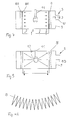
- a schematic diagram of the separator is in Fig. 1 of the drawing seen.
- the existing filter system has the disadvantage that at Saturation is no longer allowed to build up the system differential pressure. This one Filter systems cannot be cleaned during use, deteriorated the suction is continuous. This can lead to blockages in the Sewage pipes come, which ultimately also leads to failure of the whole Toilet systems can lead. Residues can also be caused by the filter stages get through and thus the outer skin of the aircraft during suction or contaminate the mechanics of the vacuum generator with impurities.
- the filter system can only be cleaned with one high effort is possible.
- the at least one waste water tank with an attached one "Waste Seperator" is usually in an aircraft, for example in an A340, located in the rear area behind the rear cargo hold.
- the too cleaning or replacing filter elements are difficult to access and This means that these parts are time-consuming and costly to install in the event of maintenance perform.
- the present invention is therefore based on the object of a filter device for a vacuum toilet system, in particular for use in a commercial aircraft, to improve such that clogging of the filter elements and thus a Impairment of the functionality of the toilet system is avoided Lifespan compared to a volume filter is increased as well as the effort for Cleaning and maintenance operations is reduced.
- FIGS. 2 to 8. 1 is in a basic representation of the prior art. In the figures are Identical components with the same reference numerals.
- a “waste separator” 100 is shown in a schematic diagram in FIG he is known from the prior art. As already in the appreciation of the State of the art, the separator 100 is in the upper region Waste water tanks 1 of an aircraft toilet system are arranged. The one from the Waste water tank 1 coming volume flow 2, consisting of air and still in Remains of the conveyed material (“waste water”) present in the air flow are removed in the separator 100 cleaned and the air is directed outside.
- a housing 101 is a first filter element 102 - consisting of a crimped Perlon thread - arranged. The filter element 102 separates the air flow from those that are still present Contamination, especially from liquid residues.
- the separated liquid 4 runs back in the lower region of the housing 101 into the waste water tank 1. Since the material to be conveyed also contains remnants of toilet paper, handkerchiefs, May contain newsprint or similar solid materials they clog the drain opening 103 or become in the filter element 102 sucked.
- a second filter element 104 is located above the first filter element 102. consisting of a coiled steel wire mesh - arranged. The of Air flowing through at the bottom is separated further and then the cleaned Volume flow 3 emitted into the outside environment via an outer line 105.
- the waste water tank 1 of a vacuum toilet system is in perspective shown.
- a filter device 5 On the top of the tank 1 there is, among other things, a filter device 5 arranged.
- the “waste separator” 100 described in FIG. 1 as a filter device is replaced by an embodiment of the filter device 5 according to the invention.
- the filter device 5 In addition to the filter device 5 are in the upper region of the waste water tank 1 Level sensor 6 and tank flushing connections 7, 7 'arranged.
- FIG. 3 is a cross-sectional illustration of the waste water tank in a schematic manner 1 with the filter device 5.
- the filter device 5 is on the top of the tank 1 arranged, a preferably cylindrical filter element 8 in a filter housing 9 is provided, which consists of the volume flow 2 from air and residues of the conveyed material still present in the air flow (“Waste water ”) is flowed through from the inside to the outside.
- the filter housing 9 is connected via a Outlet 10 connected to an outer line, the cleaned volume flow 3 released to the outside environment via the outlet 10.
- a cleaning unit 11 is required for cleaning the filter element 8 provided that rinses the filter surface with water.
- the filter device 5 is in the two Functions "Operation of the vacuum toilet system” and "Maintenance operation” shown.
- Fig. 4 shows the flow through the filter device 5 during operation of the vacuum toilet system.
- the filter element 8 is a surface filter trained and is installed as a filter cartridge in the filter housing 9.
- the Filter material is folded like a fan in the filter cartridge and forms ribs, as if 4A can be seen. The necessary size of the flow area is thus achieved. It there is no need to fold the filter material if it is sufficient Flow area already without a fan-like folding of the filter material is achieved.
- a PTFE membrane filter is used as the filter element 8 used, where the dirt particles are deposited on the surface of the filter become.
- Stretching PTFE creates a microporous PTFE membrane, which is relatively thin (for example approx. 50 ⁇ m) and after works on the principle of surface filtration.
- the PTFE membrane is on a suitable carrier material, for example fabric made of synthetic fibers such as Polyester fleece, applied.
- the PTFE membrane material is also, for example known as GORE-TEX. Thanks to the non-stick properties of PTFE (Polytetrafluoroethylene) the filter surface is only slightly soiled, clogging as with a volume filter, cannot occur. The flow through the filter element 8 takes place from the inside out, i.e.
- the uncleaned Volume flow 2 is after the flow as a cleaned volume flow 3 discharged through the outlet 10. Due to the non-stick properties of the PTFE membrane filters 8A are the separated impurities, especially the Liquid residues run off into the waste water tank 1 due to gravity alone. If dirt particles remain adhering to FIG. 5, the filter element can be cleaned 8 done by rinsing the filter surface. This is what the cleaning unit is for 11 is provided, which is arranged in the center of the filter element 8.
- the Cleaning unit 11 is fed with rinse water and preferably has one rotating water nozzle 12 on the provision of a certain water pressure is rotated.
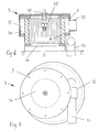
- the filter device 5 is shown in cross-section in FIGS as well as shown in a top view.
- the filter housing 9 is on the Top of the waste water tank 1 arranged.
- the filter element 8 is introduced, with a flow channel 13 between Housing wall 9A and filter element 8 remains to drain the to allow cleaned volume flow 3 to the laterally arranged outlet 10.
- the volume flow 2 to be cleaned flows in via the Inlet 15.
- the filter element 8 can preferably be supported with stabilizers or be placed in a support cage (not shown) to provide sufficient To achieve stability of this component.
- the filter housing 9 faces the waste water tank 1 out a sufficiently large drain opening 14 to the separated impurities derived from the filter element 8.
- FIG. 8 shows a second embodiment 20 of the filter device according to the invention 5 shown.
- the principle of operation of this filter device 5 is referred to the foregoing description because of the construction of this embodiment the first embodiment is the same and only the cleaning unit 11 is not provided in this embodiment.
- a PTFE membrane filter 8 is also without the possibility of rinsing the filter surface an improvement of the filter properties compared to the previous state of the Technology achieved.
- this embodiment 20 can be used, since the water connection necessary for the cleaning unit 11 is eliminated can and thus a simple exchange of the previous filter devices with the filter device 5 according to the invention is possible.
- the filter surface Rinsing can only be slightly contaminated during operation of the vacuum toilet the filter surface during maintenance inspections and a Complete replacement of the filter element 8 is only necessary at larger intervals.
Landscapes
- Chemical & Material Sciences (AREA)
- Chemical Kinetics & Catalysis (AREA)
- Engineering & Computer Science (AREA)
- Analytical Chemistry (AREA)
- General Chemical & Material Sciences (AREA)
- Oil, Petroleum & Natural Gas (AREA)
- Sanitary Device For Flush Toilet (AREA)
- Vehicle Waterproofing, Decoration, And Sanitation Devices (AREA)
- Separation Using Semi-Permeable Membranes (AREA)
Abstract
Description
- Fig. 1
- eine Prinzipdarstellung eines bekannten Filtersystems für ein Flugzeugabwassersystem,
- Fig. 2
- eine Perspektivdarstellung eines Abwassertanks eines Flugzeugabwassersystems,
- Fig. 3
- einen Querschnitt durch den Abwassertank mit einer erfindungsgemäßen Filtereinrichtung in einer schematischen Darstellung,
- Fign. 4 und 5
- Funktionsdarstellungen der erfindungsgemäßen Filtereinrichtung,
- Fig. 6
- ein Querschnitt durch die erfindungsgemäße Filtereinrichtung,
- Fig. 7
- die Filtereinrichtung gemäß Fig. 6 in einer Draufsicht und
- Fig. 8
- die erfindungsgemäße Filtereinrichtung in einer zweiten Ausführungsform.
- 100
- - Waste-Separator
- 101
- - Gehäuse
- 102
- - erstes Filterelement
- 103
- - Öffnung im Gehäuse 101
- 104
- - zweites Filterelement
- 105
- - Außenleitung
- 1
- - Abwassertank
- 2
- - ungereinigter Volumenstrom
- 3
- - gereinigter Volumenstrom
- 4
- - Abwasser (waste water)
- 5
- - Filtereinrichtung
- 6
- - Füllstandssensor
- 7, 7'
- - Spülwasseranschlüsse
- 8
- - Filterelement
- 8A
- - PTFE-Membran
- 8B
- - Trägermaterial
- 9
- - Filtergehäuse
- 9A
- - Gehäusewandung
- 10
- - Auslass
- 11
- - Reinigungseinheit
- 12
- - Wasserdüse
- 13
- - Strömungskanal
- 14
- - Ablauföffnung
- 15
- - Einlass
- 20
- - zweite Ausführungsform der Filtereinrichtung
Claims (8)
- Filtereinrichtung (5) für ein Vakuumtoilettensystem, wobei mindestens ein Filterelement (8) zum Entfernen von Verunreinigungen aus einem Volumenstrom (2) vorgesehen ist und das Filterelement (8) in einem Filtergehäuse (9) angeordnet ist, welches in Verbindung mit der Oberseite des Abwassertanks (1) steht, dadurch gekennzeichnet, dass
das Filterelement (8) als PTFE-Membranfilter ausgebildet ist, der in dem Filtergehäuse (9) angeordnet ist, zwischen dem Filterelement (8) und der Gehäusewandung (9A) ein Strömungskanal (13) gebildet ist, der in einen Auslass (10) zum Ableiten des gereinigten Volumenstromes (3) endet und auf der zuerst durchströmten Fläche des Filterelementes (8) die PTFE-Membran (8A) vorgesehen ist zum Abscheiden der separierten Verunreinigungen, wobei die Verunreinigungen (4) durch eine Ablauföffnung (14) in den Abwassertank (1) leitbar sind. - Filtereinrichtung nach Anspruch 1, dadurch gekennzeichnet, dass die PTFE-Membranschicht (8A) auf ein Trägermaterial (8B) aufgebracht ist.
- Filtereinrichtung nach einem der Ansprüche 1 oder 2, dadurch gekennzeichnet, dass der PTFE-Membranfilter (8) zylindrisch geformt ist
- Filtereinrichtung nach einem der Ansprüche 1 bis 3, dadurch gekennzeichnet, dass der PTFE-Membranfilter (8) fächerartig gefaltet ist zur Vergrößerung der Durchströmfläche.
- Filtereinrichtung nach einem der Ansprüche 1 bis 4, dadurch gekennzeichnet, dass der PTFE-Membranfilter (8) durch Stabilisatoren oder durch einen Stützkäfig gehalten wird und diese Elemente eine Filterpatrone bilden.
- Filtereinrichtung nach einem der Ansprüche 1 bis 5, dadurch gekennzeichnet, dass eine Reinigungseinheit (11) zum Reinigen der Filteroberfläche des PTFE-Membranfilters (8) vorgesehen ist.
- Filtereinrichtung nach Anspruch 6, dadurch gekennzeichnet, dass die Reinigungseinheit (11) mittels Sprühdüsen zum Besprühen der Filteroberfläche mit Spülflüssigkeit realisiert ist und die Spülflüssigkeit mit den Verunreinigungen unter Schwerkraftwirklung durch die Ablauföffnung (14) in den Abwassertank (1) abläuft.
- Filtereinrichtung nach einem der Ansprüche 6 oder 7, dadurch gekennzeichnet, dass die Reinigungseinheit (11) eine rotierende Wasserdüse (12) aufweist.
Applications Claiming Priority (2)
| Application Number | Priority Date | Filing Date | Title |
|---|---|---|---|
| DE10204248A DE10204248B4 (de) | 2002-02-02 | 2002-02-02 | Filtereinrichtung für ein Vakuumtoilettensystem |
| DE10204248 | 2002-02-02 |
Publications (2)
| Publication Number | Publication Date |
|---|---|
| EP1332785A1 true EP1332785A1 (de) | 2003-08-06 |
| EP1332785B1 EP1332785B1 (de) | 2004-07-07 |
Family
ID=7713588
Family Applications (1)
| Application Number | Title | Priority Date | Filing Date |
|---|---|---|---|
| EP03001698A Expired - Lifetime EP1332785B1 (de) | 2002-02-02 | 2003-01-27 | Filtereinrichtung für ein Vakuumtoilettensystem |
Country Status (5)
| Country | Link |
|---|---|
| US (1) | US6681412B2 (de) |
| EP (1) | EP1332785B1 (de) |
| AT (1) | ATE270578T1 (de) |
| DE (2) | DE10204248B4 (de) |
| ES (1) | ES2225801T3 (de) |
Cited By (1)
| Publication number | Priority date | Publication date | Assignee | Title |
|---|---|---|---|---|
| CN114570130A (zh) * | 2022-03-16 | 2022-06-03 | 郑州轻工业大学 | 一种生物发酵空气多级过滤除菌设备 |
Families Citing this family (11)
| Publication number | Priority date | Publication date | Assignee | Title |
|---|---|---|---|---|
| EP1541330B1 (de) | 2002-06-18 | 2010-11-03 | AMADA COMPANY, Ltd. | Presse mit einem servoantriebssystem |
| US7222868B2 (en) * | 2005-06-01 | 2007-05-29 | Steelcase Development Corporation | Seating unit with wheelchair base |
| DE102005043791A1 (de) * | 2005-09-13 | 2007-03-15 | Mann + Hummel Gmbh | Einrichtung zur Reinigung von Luft |
| DE102006053589B4 (de) * | 2006-11-14 | 2011-09-15 | Airbus Operations Gmbh | Anordnung zur thermischen Entsorgung von Abwasser eines Luftfahrzeugs |
| US7610708B2 (en) * | 2007-01-11 | 2009-11-03 | Scholl Margaret C | Chair rail picture frame |
| SE531095C2 (sv) * | 2007-09-07 | 2008-12-16 | Electrolux Ab | Dammsugare |
| DE102008058750B4 (de) | 2008-11-24 | 2019-04-11 | Airbus Operations Gmbh | Zyklonabscheider |
| DE102010035912A1 (de) | 2010-08-31 | 2012-03-01 | Airbus Operations Gmbh | Abscheidevorrichtung für Vakuumtoilettensysteme |
| US8771393B1 (en) * | 2011-08-29 | 2014-07-08 | Exelis, Inc. | Integrated polar cap for a vacuum waste tank system |
| US9756999B2 (en) | 2014-12-22 | 2017-09-12 | Aktiebolaget Electrolux | Vacuum cleaner filtration system with filter cleaning mode |
| CN105756159B (zh) * | 2016-05-17 | 2018-11-27 | 北京华盛路泰科技有限公司 | 具有自动集污功能的厕所 |
Citations (2)
| Publication number | Priority date | Publication date | Assignee | Title |
|---|---|---|---|---|
| EP0474271A2 (de) * | 1990-09-06 | 1992-03-11 | The Boeing Company | Externer Separator für Absaugsysteme |
| US6206943B1 (en) * | 1997-09-10 | 2001-03-27 | Edo Fiber Science | Separator system for aircraft waste system |
Family Cites Families (4)
| Publication number | Priority date | Publication date | Assignee | Title |
|---|---|---|---|---|
| US4070714A (en) * | 1974-02-27 | 1978-01-31 | Monogram Industries, Inc. | Sewerless recirculating toilet and human waste storage system |
| EP0630281B1 (de) * | 1991-11-15 | 1996-05-22 | Memtec America Corporation | Gefaltetes filtermittel aus poly(tetrafluoroethylen) und träger |
| US5538546A (en) * | 1992-10-27 | 1996-07-23 | E. I. Du Pont De Nemours And Company | Waste tank for vacuum sewage system |
| KR19990023033A (ko) * | 1995-06-20 | 1999-03-25 | 노르만 시이 린넬/기에르츠 제임스 알 | 필터 및 필터를 제조하는 방법 |
-
2002
- 2002-02-02 DE DE10204248A patent/DE10204248B4/de not_active Expired - Fee Related
- 2002-08-30 US US10/232,354 patent/US6681412B2/en not_active Expired - Lifetime
-
2003
- 2003-01-27 DE DE50300027T patent/DE50300027D1/de not_active Expired - Lifetime
- 2003-01-27 AT AT03001698T patent/ATE270578T1/de not_active IP Right Cessation
- 2003-01-27 ES ES03001698T patent/ES2225801T3/es not_active Expired - Lifetime
- 2003-01-27 EP EP03001698A patent/EP1332785B1/de not_active Expired - Lifetime
Patent Citations (2)
| Publication number | Priority date | Publication date | Assignee | Title |
|---|---|---|---|---|
| EP0474271A2 (de) * | 1990-09-06 | 1992-03-11 | The Boeing Company | Externer Separator für Absaugsysteme |
| US6206943B1 (en) * | 1997-09-10 | 2001-03-27 | Edo Fiber Science | Separator system for aircraft waste system |
Cited By (2)
| Publication number | Priority date | Publication date | Assignee | Title |
|---|---|---|---|---|
| CN114570130A (zh) * | 2022-03-16 | 2022-06-03 | 郑州轻工业大学 | 一种生物发酵空气多级过滤除菌设备 |
| CN114570130B (zh) * | 2022-03-16 | 2023-08-18 | 郑州轻工业大学 | 一种生物发酵空气多级过滤除菌设备 |
Also Published As
| Publication number | Publication date |
|---|---|
| ES2225801T3 (es) | 2005-03-16 |
| DE50300027D1 (de) | 2004-08-12 |
| DE10204248B4 (de) | 2006-02-02 |
| EP1332785B1 (de) | 2004-07-07 |
| DE10204248A1 (de) | 2003-08-28 |
| US6681412B2 (en) | 2004-01-27 |
| ATE270578T1 (de) | 2004-07-15 |
| US20030145372A1 (en) | 2003-08-07 |
Similar Documents
| Publication | Publication Date | Title |
|---|---|---|
| DE102007048550B4 (de) | Kraftstofffilter | |
| EP2145099B1 (de) | Kraftstoffzuführeinrichtung, insbesondere für eine brennkraftmaschine | |
| EP1332785B1 (de) | Filtereinrichtung für ein Vakuumtoilettensystem | |
| EP2663378B1 (de) | Filtervorrichtung | |
| DE2825273A1 (de) | Abscheider | |
| EP2249941A1 (de) | Filtervorrichtung sowie filterelement für eine solche filtervorrichtung | |
| EP2788099A1 (de) | Kraftstofffilter einer brennkraftmaschine und filterelement eines kraftstofffilters | |
| DE202009002303U1 (de) | Wasserabscheider, insbesondere für Kraftstoffzuführsysteme von Brennkraftmaschinen in Kraftfahrzeugen | |
| DE102005005848A1 (de) | Filtersystem für Kraftstoff | |
| DE102011119868A1 (de) | Filtervorrichtung | |
| DE102008055045A1 (de) | Staubsauger mit Fliehkraftabscheidern | |
| DE102012013743A1 (de) | Wasserabscheidevorrichtung, Filterelement eines Kraftstoff-Filters und Kraftstofffilter | |
| DE102017003732A1 (de) | Flüssigkeitsfilter zur Wasserabscheidung und/oder Partikelfiltration eines Kraftstoffs und/oder einer wässrigen Lösung, insbesondere einer Harnstofflösung, und/oder Wasser | |
| DE102004036083B4 (de) | Ansaugvorrichtung | |
| DE2728137C2 (de) | Filtervorrichtung für industrielle Abwässer | |
| DE102004041768B4 (de) | Fliehkraftabscheider | |
| EP0655269B1 (de) | Flüssigkeitsfilter für Kraftstoff | |
| DE102010044773A1 (de) | Kraftstofffilter zur Filterung von Kraftstoff | |
| DE202008002927U1 (de) | Flüssigkeitsfilter, insbesondere für Kraftstoff | |
| DE3826454C2 (de) | ||
| WO2013120753A1 (de) | Filterkomponente und herstellung der filterkomponente mit hydrophoben und hydrophilen bereichen zur kolloidalen-trennung | |
| EP1544452B1 (de) | Zweistufiger Kraftstofffilter | |
| DE102018208751B4 (de) | Flüssigkeitsbehälter | |
| DE202006005677U1 (de) | Vorrichtung zum Reinigen von Rohgas | |
| DE4218808C2 (de) | Vorrichtung zur Kanalreinigung |
Legal Events
| Date | Code | Title | Description |
|---|---|---|---|
| PUAI | Public reference made under article 153(3) epc to a published international application that has entered the european phase |
Free format text: ORIGINAL CODE: 0009012 |
|
| 17P | Request for examination filed |
Effective date: 20030602 |
|
| AK | Designated contracting states |
Designated state(s): AT BE BG CH CY CZ DE DK EE ES FI FR GB GR HU IE IT LI LU MC NL PT SE SI SK TR |
|
| AX | Request for extension of the european patent |
Extension state: AL LT LV MK RO |
|
| GRAP | Despatch of communication of intention to grant a patent |
Free format text: ORIGINAL CODE: EPIDOSNIGR1 |
|
| AKX | Designation fees paid |
Designated state(s): AT BE BG CH CY CZ DE DK EE ES FI FR GB GR HU IE IT LI LU MC NL PT SE SI SK TR |
|
| GRAS | Grant fee paid |
Free format text: ORIGINAL CODE: EPIDOSNIGR3 |
|
| GRAA | (expected) grant |
Free format text: ORIGINAL CODE: 0009210 |
|
| AK | Designated contracting states |
Kind code of ref document: B1 Designated state(s): AT BE BG CH CY CZ DE DK EE ES FI FR GB GR HU IE IT LI LU MC NL PT SE SI SK TR |
|
| PG25 | Lapsed in a contracting state [announced via postgrant information from national office to epo] |
Ref country code: SK Free format text: LAPSE BECAUSE OF FAILURE TO SUBMIT A TRANSLATION OF THE DESCRIPTION OR TO PAY THE FEE WITHIN THE PRESCRIBED TIME-LIMIT Effective date: 20040707 Ref country code: FI Free format text: LAPSE BECAUSE OF FAILURE TO SUBMIT A TRANSLATION OF THE DESCRIPTION OR TO PAY THE FEE WITHIN THE PRESCRIBED TIME-LIMIT Effective date: 20040707 Ref country code: BG Free format text: LAPSE BECAUSE OF FAILURE TO SUBMIT A TRANSLATION OF THE DESCRIPTION OR TO PAY THE FEE WITHIN THE PRESCRIBED TIME-LIMIT Effective date: 20040707 Ref country code: IE Free format text: LAPSE BECAUSE OF FAILURE TO SUBMIT A TRANSLATION OF THE DESCRIPTION OR TO PAY THE FEE WITHIN THE PRESCRIBED TIME-LIMIT Effective date: 20040707 Ref country code: TR Free format text: LAPSE BECAUSE OF FAILURE TO SUBMIT A TRANSLATION OF THE DESCRIPTION OR TO PAY THE FEE WITHIN THE PRESCRIBED TIME-LIMIT Effective date: 20040707 Ref country code: EE Free format text: LAPSE BECAUSE OF FAILURE TO SUBMIT A TRANSLATION OF THE DESCRIPTION OR TO PAY THE FEE WITHIN THE PRESCRIBED TIME-LIMIT Effective date: 20040707 Ref country code: CZ Free format text: LAPSE BECAUSE OF FAILURE TO SUBMIT A TRANSLATION OF THE DESCRIPTION OR TO PAY THE FEE WITHIN THE PRESCRIBED TIME-LIMIT Effective date: 20040707 Ref country code: SI Free format text: LAPSE BECAUSE OF FAILURE TO SUBMIT A TRANSLATION OF THE DESCRIPTION OR TO PAY THE FEE WITHIN THE PRESCRIBED TIME-LIMIT Effective date: 20040707 |
|
| REG | Reference to a national code |
Ref country code: GB Ref legal event code: FG4D Free format text: NOT ENGLISH |
|
| REG | Reference to a national code |
Ref country code: CH Ref legal event code: EP |
|
| REG | Reference to a national code |
Ref country code: IE Ref legal event code: FG4D Free format text: GERMAN |
|
| REF | Corresponds to: |
Ref document number: 50300027 Country of ref document: DE Date of ref document: 20040812 Kind code of ref document: P |
|
| PG25 | Lapsed in a contracting state [announced via postgrant information from national office to epo] |
Ref country code: GR Free format text: LAPSE BECAUSE OF FAILURE TO SUBMIT A TRANSLATION OF THE DESCRIPTION OR TO PAY THE FEE WITHIN THE PRESCRIBED TIME-LIMIT Effective date: 20041007 Ref country code: DK Free format text: LAPSE BECAUSE OF FAILURE TO SUBMIT A TRANSLATION OF THE DESCRIPTION OR TO PAY THE FEE WITHIN THE PRESCRIBED TIME-LIMIT Effective date: 20041007 |
|
| PG25 | Lapsed in a contracting state [announced via postgrant information from national office to epo] |
Ref country code: HU Free format text: LAPSE BECAUSE OF FAILURE TO SUBMIT A TRANSLATION OF THE DESCRIPTION OR TO PAY THE FEE WITHIN THE PRESCRIBED TIME-LIMIT Effective date: 20041008 |
|
| REG | Reference to a national code |
Ref country code: SE Ref legal event code: TRGR |
|
| GBT | Gb: translation of ep patent filed (gb section 77(6)(a)/1977) | ||
| PG25 | Lapsed in a contracting state [announced via postgrant information from national office to epo] |
Ref country code: LU Free format text: LAPSE BECAUSE OF NON-PAYMENT OF DUE FEES Effective date: 20050127 Ref country code: CY Free format text: LAPSE BECAUSE OF FAILURE TO SUBMIT A TRANSLATION OF THE DESCRIPTION OR TO PAY THE FEE WITHIN THE PRESCRIBED TIME-LIMIT Effective date: 20050127 |
|
| PG25 | Lapsed in a contracting state [announced via postgrant information from national office to epo] |
Ref country code: MC Free format text: LAPSE BECAUSE OF NON-PAYMENT OF DUE FEES Effective date: 20050131 Ref country code: BE Free format text: LAPSE BECAUSE OF NON-PAYMENT OF DUE FEES Effective date: 20050131 Ref country code: AT Free format text: LAPSE BECAUSE OF NON-PAYMENT OF DUE FEES Effective date: 20050131 |
|
| REG | Reference to a national code |
Ref country code: ES Ref legal event code: FG2A Ref document number: 2225801 Country of ref document: ES Kind code of ref document: T3 |
|
| REG | Reference to a national code |
Ref country code: IE Ref legal event code: FD4D |
|
| PLBE | No opposition filed within time limit |
Free format text: ORIGINAL CODE: 0009261 |
|
| STAA | Information on the status of an ep patent application or granted ep patent |
Free format text: STATUS: NO OPPOSITION FILED WITHIN TIME LIMIT |
|
| ET | Fr: translation filed | ||
| 26N | No opposition filed |
Effective date: 20050408 |
|
| BERE | Be: lapsed |
Owner name: *AIRBUS DEUTSCHLAND G.M.B.H. Effective date: 20050131 |
|
| PG25 | Lapsed in a contracting state [announced via postgrant information from national office to epo] |
Ref country code: LI Free format text: LAPSE BECAUSE OF NON-PAYMENT OF DUE FEES Effective date: 20070131 Ref country code: CH Free format text: LAPSE BECAUSE OF NON-PAYMENT OF DUE FEES Effective date: 20070131 |
|
| REG | Reference to a national code |
Ref country code: CH Ref legal event code: PL |
|
| BERE | Be: lapsed |
Owner name: *AIRBUS DEUTSCHLAND G.M.B.H. Effective date: 20050131 |
|
| PG25 | Lapsed in a contracting state [announced via postgrant information from national office to epo] |
Ref country code: PT Free format text: LAPSE BECAUSE OF NON-PAYMENT OF DUE FEES Effective date: 20041207 |
|
| REG | Reference to a national code |
Ref country code: ES Ref legal event code: PC2A Owner name: AIRBUS OPERATIONS GMBH Effective date: 20110930 |
|
| REG | Reference to a national code |
Ref country code: FR Ref legal event code: CD Owner name: AIRBUS OPERATIONS GMBH Effective date: 20111118 |
|
| REG | Reference to a national code |
Ref country code: FR Ref legal event code: PLFP Year of fee payment: 14 |
|
| PGFP | Annual fee paid to national office [announced via postgrant information from national office to epo] |
Ref country code: NL Payment date: 20160120 Year of fee payment: 14 |
|
| PGFP | Annual fee paid to national office [announced via postgrant information from national office to epo] |
Ref country code: DE Payment date: 20160120 Year of fee payment: 14 Ref country code: IT Payment date: 20160127 Year of fee payment: 14 Ref country code: ES Payment date: 20160112 Year of fee payment: 14 |
|
| PGFP | Annual fee paid to national office [announced via postgrant information from national office to epo] |
Ref country code: FR Payment date: 20160121 Year of fee payment: 14 Ref country code: SE Payment date: 20160120 Year of fee payment: 14 Ref country code: GB Payment date: 20160120 Year of fee payment: 14 |
|
| REG | Reference to a national code |
Ref country code: DE Ref legal event code: R119 Ref document number: 50300027 Country of ref document: DE |
|
| REG | Reference to a national code |
Ref country code: NL Ref legal event code: MM Effective date: 20170201 |
|
| GBPC | Gb: european patent ceased through non-payment of renewal fee |
Effective date: 20170127 |
|
| REG | Reference to a national code |
Ref country code: FR Ref legal event code: ST Effective date: 20170929 |
|
| PG25 | Lapsed in a contracting state [announced via postgrant information from national office to epo] |
Ref country code: FR Free format text: LAPSE BECAUSE OF NON-PAYMENT OF DUE FEES Effective date: 20170131 |
|
| PG25 | Lapsed in a contracting state [announced via postgrant information from national office to epo] |
Ref country code: GB Free format text: LAPSE BECAUSE OF NON-PAYMENT OF DUE FEES Effective date: 20170127 Ref country code: DE Free format text: LAPSE BECAUSE OF NON-PAYMENT OF DUE FEES Effective date: 20170801 Ref country code: SE Free format text: LAPSE BECAUSE OF NON-PAYMENT OF DUE FEES Effective date: 20170128 Ref country code: NL Free format text: LAPSE BECAUSE OF NON-PAYMENT OF DUE FEES Effective date: 20170201 |
|
| PG25 | Lapsed in a contracting state [announced via postgrant information from national office to epo] |
Ref country code: IT Free format text: LAPSE BECAUSE OF NON-PAYMENT OF DUE FEES Effective date: 20170127 |
|
| PG25 | Lapsed in a contracting state [announced via postgrant information from national office to epo] |
Ref country code: ES Free format text: LAPSE BECAUSE OF NON-PAYMENT OF DUE FEES Effective date: 20170128 |
|
| REG | Reference to a national code |
Ref country code: ES Ref legal event code: FD2A Effective date: 20181113 |