EP1332717A1 - Cuff for blood pressure monitor - Google Patents
Cuff for blood pressure monitor Download PDFInfo
- Publication number
- EP1332717A1 EP1332717A1 EP03000087A EP03000087A EP1332717A1 EP 1332717 A1 EP1332717 A1 EP 1332717A1 EP 03000087 A EP03000087 A EP 03000087A EP 03000087 A EP03000087 A EP 03000087A EP 1332717 A1 EP1332717 A1 EP 1332717A1
- Authority
- EP
- European Patent Office
- Prior art keywords
- elastic member
- arm
- cuff
- curled elastic
- blood pressure
- Prior art date
- Legal status (The legal status is an assumption and is not a legal conclusion. Google has not performed a legal analysis and makes no representation as to the accuracy of the status listed.)
- Granted
Links
Images


Classifications
-
- A—HUMAN NECESSITIES
- A61—MEDICAL OR VETERINARY SCIENCE; HYGIENE
- A61B—DIAGNOSIS; SURGERY; IDENTIFICATION
- A61B5/00—Measuring for diagnostic purposes; Identification of persons
- A61B5/02—Detecting, measuring or recording for evaluating the cardiovascular system, e.g. pulse, heart rate, blood pressure or blood flow
- A61B5/021—Measuring pressure in heart or blood vessels
- A61B5/022—Measuring pressure in heart or blood vessels by applying pressure to close blood vessels, e.g. against the skin; Ophthalmodynamometers
- A61B5/02233—Occluders specially adapted therefor
Landscapes
- Health & Medical Sciences (AREA)
- Life Sciences & Earth Sciences (AREA)
- Cardiology (AREA)
- Vascular Medicine (AREA)
- Engineering & Computer Science (AREA)
- Medical Informatics (AREA)
- Physics & Mathematics (AREA)
- Ophthalmology & Optometry (AREA)
- Biophysics (AREA)
- Pathology (AREA)
- Dentistry (AREA)
- Biomedical Technology (AREA)
- Heart & Thoracic Surgery (AREA)
- Physiology (AREA)
- Molecular Biology (AREA)
- Surgery (AREA)
- Animal Behavior & Ethology (AREA)
- General Health & Medical Sciences (AREA)
- Public Health (AREA)
- Veterinary Medicine (AREA)
- Measuring Pulse, Heart Rate, Blood Pressure Or Blood Flow (AREA)
Abstract
Description
- The present invention relates to a cuff for a blood pressure monitor and, more particularly, to a cuff characterized by a curled elastic member disposed on the outside of a bladder to hold a ring form of the cuff.
- As shown in Fig. 6 (perspective view) and Fig. 7 (section view), a cuff for a blood pressure monitor has generally a configuration such that a
bladder 31 and a curledelastic member 32 are provided in acloth bag 30. Atube 33 is connected to thebladder 31, and a Velcrofastener 34 is attached on the outside of thecloth bag 30. The curledelastic member 32 is disposed on the outside of thebladder 31 to hold the cuff in a ring form by its elasticity. As shown in Fig. 8, the curledelastic member 32 has a uniform thickness and has a sectional shape of a complete round in which a part thereof is a discontinuous portion 32a. - In the curled
elastic member 32 shown in Fig. 8, however, there have been the following problems. - 1. When the curled
elastic member 32 is attached around an arm, the edges of the discontinuous portion 32a of the curled elastic member cut into the flesh of the arm due to its elastic force so that users in particular with thick arm often feel pain. - 2. Since the curled
elastic member 32 has uniform thickness and the sectional shape thereof is complete round, it cannot deform so as to correspond to a person with thick arm or a person with thin arm and hence is difficult to fit with such arms. -
- For addressing the above described problems, Japanese Unexamined Patent Publication No. S61-238229 (1986) proposes a curled elastic member 42 as shown in Fig. 9. This curled elastic member 42 is so configured that its thickness gradually increases in a circumferential direction of an arm from the both ends toward the center portion and, and hence the rigidity of the curled elastic member 42 gradually increases. The thickness and rigidity are the maximum at the center portion.
- This curled elastic member 42 has somewhat solved the aforementioned problems, however, for an arm whose diameter changes to large extent depending on the part of the arm, or in other words, a largely-inclined arm, such as an upper arm whose diameter is small in the vicinity of the elbow but gradually increases toward the shoulder, the curled elastic member 42 fits with the large diameter part of the arm while leaving a clearance with respect to the small diameter part of the arm. As described above, the curled elastic member 42 cannot sufficiently deform to correspond to the shape of the arm.
- The present invention was devised to solve the above-mentioned problems associated with the prior art, and it is an object of the present invention to provide a cuff for a blood pressure monitor with excellent fitting ability which can fit various shapes of arms, in particular, largely-inclined arms.
- In order to achieve the above-mentioned object, a cuff for a blood pressure monitor of the present invention has therein a bladder and a curled elastic member disposed on the outside of the bladder to hold a ring shape of the cuff, and is characterized in that the curled elastic member has nonuniform rigidity in a ring-shaped axial direction of an arm. According to this curled elastic member, since the part having high rigidity is tightly fastened at the time of attachment around an arm and the part having low rigidity conforms to the shape of the arm, it is possible to attach it in conformance with the shape of the arm.
- In addition, if the curled elastic member has high rigidity in the part corresponding to the side where the diameter of the arm around which the cuff is to be attached is small, and has low rigidity in the part corresponding to the side where the diameter of the arm is larger, it can be attached in conformance with, in particular, largely-inclined arms.
- Furthermore, the curled elastic member may have nonuniform rigidity in a ring-shaped circumferential direction of an arm. As a result of this, the curled elastic member can easily twist and conform to a wide variety of shapes of arms.
- Furthermore, the curled elastic member may have low rigidity at an end portion which is to be positioned inside when attached around an arm. As a result of this, the end portion which is brought into contact with an arm at the time of attachment conforms to the shape of the arm, so that pain to the arm can be reduced.
- In this curled elastic member, a part having low rigidity may be formed by reducing the thickness. As a result of this, it is possible to readily form regions having different rigidities. Furthermore, in the curled elastic member, a part having low rigidity may be formed by joining at least two members having different shapes and providing a region where at least two members do not overlap with each other. As a result of this, it is possible to deal with different rigidities using more conditions.
- Furthermore, in the curled elastic member, a part having low rigidity may be formed by performing punching or boring process on a material. It is possible to set a difference in rigidity more suitably in accordance with the settings such as descending position of hole (bore), density, diameter of hole (or bore) and the like.
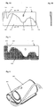
- A perspective view of a curled elastic member in the first embodiment of the present invention.
- An exploded view of a curled elastic member in the first embodiment of the present invention.
- A perspective view of a curled elastic member in the second embodiment of the present invention.
- An exploded view of a curled elastic member in the second embodiment of the present invention.
- An exploded view of a curled elastic member in the third embodiment of the present invention.
- A perspective view showing appearance of a curled elastic member of a general cuff for a blood pressure monitor.
- A section view showing the interior of the cuff shown in Fig. 6.
- A perspective view showing a conventional curled elastic member.
- A perspective view showing a conventional curled elastic member.
- Preferred embodiments of the present invention will be described with reference to the drawings hereinafter. It is to be noted that the cuff for a blood pressure monitor in the present invention has its feature in a curled elastic member thereof, and a structure of the cuff except for the curled elastic member may be a conventional one as shown in Fig. 6. Accordingly, the following explanation focuses on the curled elastic member. The operation associated with this curled elastic member is also maintained in a cuff having the curled elastic member.
- Fig. 1 and Fig. 2A are a perspective view and an exploded view showing a curled elastic member provided for a cuff for a blood pressure monitor, according to the first embodiment of the present invention. A section view viewed from the right direction along the line A-A' of Fig. 2A is shown in Fig. 2B. A curled
elastic member 1 is formed of a resin such as PP (polypropylene), and includes two regions having different thicknesses: athin portion 2 and a thick portion 3. When the curledelastic member 1 is attached around an arm, it is wounded so that oneend portion 4 is placed inside anotherend portion 5. Attention is now directed to an axial direction of an arm in the condition that the curledelastic member 1 is attached around an arm, and it can be seen that one end of the cylindrically wound curledelastic member 1 forms thethin portion 2 and the other end forms the thick portion 3. The thick portion 3 has high rigidity so that it can firmly wind the arm, whereas thethin portion 2 has low rigidity so that it can easily deform in conformance with the shape of the arm in contrast to the thick portion 3. Consequently, when the curledelastic member 1 is oriented so that the thick portion 3 corresponds to the arm part of small diameter and thethin portion 2 corresponds to the arm part of large diameter, and the curledelastic member 1 is wound so that no clearance is left between the thick portion 3 and the arm part of small diameter, thethin portion 2 deforms to closely attach to the arm part of large diameter, resulting that it can be attached around the entire circumference of the arm without leaving any clearance. - In the first embodiment, the rigidity of the curled
elastic member 1 is varied in two steps, however, the rigidity may be set more finely, or may be continuously varied by, for example, gradually changing the thickness in the axial direction of an arm from the one end side to the other end side as illustrated in the section view of Fig. 2C. - Fig. 3 and Fig. 4A are a perspective view and an exploded view showing a curled elastic member provided for a cuff for a blood pressure monitor, according to the second embodiment of the present invention. A section view viewed from the right direction along the line B-B' of Fig. 4A is shown in Fig. 4B. A curled
elastic member 11 includes two regions having different thicknesses: athin portion 12 and athick portion 13. When the curledelastic member 11 is attached around an upper arm, it is wounded so that thethin portion 12 is located on the shoulder side and oneend portion 14 is placed inside another end portion 15. Attention is now directed to an axial direction of an arm in the condition that the curledelastic member 11 is attached around the upper arm, and then it can be seen that the part corresponding to the shoulder side forms thethin portion 12 and the part corresponding to the elbow side forms thethick portion 13. Accordingly, likewise the curledelastic member 1 according to the first embodiment of the present invention provided for the cuff of a blood pressure monitor, when thethick portion 13 having high rigidity is wound around the arm part near the elbow where the diameter is smaller than that of the part on the shoulder side so as not to leave a clearance, thethin portion 12 having lower rigidity deforms to be closely attached to the arm part on the shoulder side where the diameter is larger than that of the elbow side. As a result of this, it can be attached around a largely-inclined arm without leaving any clearance. - Next, attention is directed to a circumferential direction of an arm, and then it can be seen that on either side of a
hole 16 through which a tube connected to a bladder (not shown) is to be inserted into the curledelastic member 11, is provided anarrow portion thick portion 13 along the axial direction of an arm is partially narrowed. Thesenarrow portions elastic member 11 is low in thesenarrow portions elastic member 11 can easily twist. - Furthermore, in the vicinity of the
hole 16 is formed a wide portion 19 where the width of thethick portion 13 along the axial direction of an arm is elongated, whereby the rigidity is set higher so as to reduce the deformation during pressurizing to the arm by the bladder. Furthermore, as for oneend portion 14 and the other end portion 15, the oneend portion 14 and its vicinity is formed as thethin portion 12 and the other end 15 and its vicinity is formed as thethick portion 13. When the cured elastic member is wound around an upper arm, the oneend portion 14 which is designed to lie inside and come into contact with the arm will conform with the shape of the arm to reduce the pain to the arm since it has low rigidity, while the other end potion 15 will ensure close attachment to the arm since it has high rigidity. - In order to form a curled elastic member having nonuniform rigidity, for example, the
thin portion 12 and thethick portion 13 may be integrally formed to make the curledelastic member 11 or the part corresponding to thethin portion 12 may be formed by cutting from a member having the entire shape of the curledelastic member 11 and having the thickness of thethick portion 13. Also, a member having a shape of the part corresponding to thethick portion 13 may be bonded on a member having the entire shape of the curledelastic member 11 formed in a thickness of thethin portion 12. At this time, it is effective to use materials of different rigidities such that the member having the entire shape is formed of a material of low rigidity and the member having a shape of the part corresponding to thethick portion 13 is formed of a material of high rigidity, for example. - The boundary pattern between the
thin portion 12 and thethick portion 13 shown in Fig. 4 which is an exploded view is not limited to the illustrated one. - Fig. 5 shows an exploded view showing a curled
elastic member 21 provided for a cuff for a blood pressure monitor, according to the third embodiment of the present invention . This curledelastic member 21 is another embodiment for implementing the same embodiment as the curledelastic member 11 according to the second embodiment, wherein the rigidities along the axial and circumferential directions of an arm are changed by effecting apunching (boring) process on the material. To be more specific, apart 22 which is intended to have low rigidity corresponding to thethin portion 12 in the curledelastic member 11 of the second embodiment is subjected to a punching (boring) process to provide a plurality of holes (or bores) 24, while a part 23 which is intended to have high rigidity corresponding to thethick part 13 is subjected to neither punching nor boring process. As a result of this, the entire thickness of the curledelastic member 21 is uniform, while the rigidity is not uniform in the axial and circumferential directions of an arm and desired rigidity distribution allowing deformation for conforming to the shape of the arm is possible. Accordingly, likewise the curledelastic member 11 according to the second embodiment, the curledelastic member 21 can be closely attached around any arms having a variety of shapes and degrees of inclination. - Operations and effects of the present invention can be achieved more effectively by allowing the position where punching or boring is effected, the processing density, the diameter of bore or hole to be arbitrarily set. The size of bore or hole is not necessarily the same with each other, but large sized and small sized bores or holes may exist in combination. Although either punching or boring process is effected in Fig. 5, processes for making holes and bores may be effected in combination. Accordingly, the pattern of punching or boring process is not limited to the one shown in Fig. 5 as is the same with the second embodiment.
- As described above, according to the cuff for a blood pressure monitor of the present invention, it is possible to fittingly attach the cuff around various shapes of arms, in particular largely-inclined arms.
Claims (7)
- A cuff for a blood pressure monitor, comprising therein a bladder and a curled elastic member disposed on the outside of the bladder to hold a ring shape of the cuff,
wherein said curled elastic member has nonuniform rigidity in a ring-shaped axial direction of an arm. - The cuff for a blood pressure monitor according to claim 1, wherein said curled elastic member has high rigidity in the part corresponding to the side where the diameter of the arm around which the cuff is to be attached is small, and has low rigidity in the part corresponding to the side where the diameter of the arm is larger.
- The cuff for a blood pressure monitor according to claim 1 or 2 , wherein said curled elastic member has nonuniform rigidity also in a ring-shaped circumferential direction of an arm.
- The cuff for a blood pressure monitor according to claim 3, wherein said curled elastic member has low rigidity at an end portion which is to be positioned inside when attached around an arm.
- The cuff for a blood pressure monitor according to any one of claims 1 to 3, wherein a part having low rigidity in said curled elastic member is formed by reducing the thickness.
- The cuff for a blood pressure monitor according to any one of claims 1 to 3, wherein a part having low rigidity in said curled elastic member is formed by joining at least two members having different shapes and providing a region where said at least two members do not overlap with each other.
- The cuff for a blood pressure monitor according to any one of claims 1 to 3, wherein a part having low rigidity in said curled elastic member is formed by conducting a punching or boring process on a material.
Applications Claiming Priority (2)
| Application Number | Priority Date | Filing Date | Title |
|---|---|---|---|
| JP2002026424A JP3622730B2 (en) | 2002-02-04 | 2002-02-04 | Sphygmomanometer arm band |
| JP2002026424 | 2002-02-04 |
Publications (2)
| Publication Number | Publication Date |
|---|---|
| EP1332717A1 true EP1332717A1 (en) | 2003-08-06 |
| EP1332717B1 EP1332717B1 (en) | 2004-08-18 |
Family
ID=19192352
Family Applications (1)
| Application Number | Title | Priority Date | Filing Date |
|---|---|---|---|
| EP20030000087 Expired - Lifetime EP1332717B1 (en) | 2002-02-04 | 2003-01-08 | Cuff for blood pressure monitor |
Country Status (4)
| Country | Link |
|---|---|
| EP (1) | EP1332717B1 (en) |
| JP (1) | JP3622730B2 (en) |
| CN (1) | CN1233296C (en) |
| DE (1) | DE60300023T2 (en) |
Cited By (6)
| Publication number | Priority date | Publication date | Assignee | Title |
|---|---|---|---|---|
| EP4663104A1 (en) * | 2024-06-12 | 2025-12-17 | Koninklijke Philips N.V. | Pressure measuring device to be used for determining a physiological parameter of a subject |
| EP4663106A1 (en) * | 2024-06-12 | 2025-12-17 | Koninklijke Philips N.V. | Pressure measuring device to be used for determining a physiological parameter of a subject |
| EP4663102A1 (en) * | 2024-06-12 | 2025-12-17 | Koninklijke Philips N.V. | Pressure measuring device to be used for determining a physiological parameter of a subject |
| EP4663105A1 (en) * | 2024-06-12 | 2025-12-17 | Koninklijke Philips N.V. | Pressure measuring device to be used for determining a physiological parameter of a subject |
| EP4663101A1 (en) * | 2024-06-12 | 2025-12-17 | Koninklijke Philips N.V. | Pressure measuring device to be used for determining a physiological parameter of a subject |
| EP4663103A1 (en) * | 2024-06-12 | 2025-12-17 | Koninklijke Philips N.V. | Pressure measuring device to be used for determining a physiological parameter of a subject |
Families Citing this family (3)
| Publication number | Priority date | Publication date | Assignee | Title |
|---|---|---|---|---|
| JP4534583B2 (en) * | 2004-05-07 | 2010-09-01 | オムロンヘルスケア株式会社 | Sphygmomanometer cuff |
| JP2006255097A (en) * | 2005-03-16 | 2006-09-28 | Omron Healthcare Co Ltd | Cuff for sphygmomanometer and sphygmomanometer |
| DE102011052797B4 (en) | 2011-08-18 | 2013-05-29 | Polygreen Germany Gmbh | Arm-wrapping tape for blood pressure gauges |
Citations (3)
| Publication number | Priority date | Publication date | Assignee | Title |
|---|---|---|---|---|
| US4572205A (en) * | 1983-09-23 | 1986-02-25 | Sjoenell Goeran | Method at blood pressure measurement and a blood pressure cuff for carrying out the method |
| JPS61238229A (en) * | 1985-04-13 | 1986-10-23 | 松下電工株式会社 | Cuff band of hemomanometer |
| JPH0638931A (en) * | 1992-07-28 | 1994-02-15 | Matsushita Electric Works Ltd | Blood pressure cuff belt |
-
2002
- 2002-02-04 JP JP2002026424A patent/JP3622730B2/en not_active Expired - Lifetime
-
2003
- 2003-01-08 DE DE2003600023 patent/DE60300023T2/en not_active Expired - Lifetime
- 2003-01-08 EP EP20030000087 patent/EP1332717B1/en not_active Expired - Lifetime
- 2003-01-24 CN CN 03102946 patent/CN1233296C/en not_active Expired - Fee Related
Patent Citations (3)
| Publication number | Priority date | Publication date | Assignee | Title |
|---|---|---|---|---|
| US4572205A (en) * | 1983-09-23 | 1986-02-25 | Sjoenell Goeran | Method at blood pressure measurement and a blood pressure cuff for carrying out the method |
| JPS61238229A (en) * | 1985-04-13 | 1986-10-23 | 松下電工株式会社 | Cuff band of hemomanometer |
| JPH0638931A (en) * | 1992-07-28 | 1994-02-15 | Matsushita Electric Works Ltd | Blood pressure cuff belt |
Non-Patent Citations (1)
| Title |
|---|
| PATENT ABSTRACTS OF JAPAN vol. 018, no. 257 (C - 1200) 17 May 1994 (1994-05-17) * |
Cited By (11)
| Publication number | Priority date | Publication date | Assignee | Title |
|---|---|---|---|---|
| EP4663104A1 (en) * | 2024-06-12 | 2025-12-17 | Koninklijke Philips N.V. | Pressure measuring device to be used for determining a physiological parameter of a subject |
| EP4663106A1 (en) * | 2024-06-12 | 2025-12-17 | Koninklijke Philips N.V. | Pressure measuring device to be used for determining a physiological parameter of a subject |
| EP4663102A1 (en) * | 2024-06-12 | 2025-12-17 | Koninklijke Philips N.V. | Pressure measuring device to be used for determining a physiological parameter of a subject |
| EP4663105A1 (en) * | 2024-06-12 | 2025-12-17 | Koninklijke Philips N.V. | Pressure measuring device to be used for determining a physiological parameter of a subject |
| EP4663101A1 (en) * | 2024-06-12 | 2025-12-17 | Koninklijke Philips N.V. | Pressure measuring device to be used for determining a physiological parameter of a subject |
| EP4663103A1 (en) * | 2024-06-12 | 2025-12-17 | Koninklijke Philips N.V. | Pressure measuring device to be used for determining a physiological parameter of a subject |
| WO2025257234A1 (en) * | 2024-06-12 | 2025-12-18 | Koninklijke Philips N.V. | Pressure measuring device to be used for determining a physiological parameter of a subject |
| WO2025257233A1 (en) * | 2024-06-12 | 2025-12-18 | Koninklijke Philips N.V. | Pressure measuring device to be used for determining a physiological parameter of a subject |
| WO2025257230A1 (en) | 2024-06-12 | 2025-12-18 | Koninklijke Philips N.V. | Pressure measuring device to be used for determining a physiological parameter of a subject |
| WO2025257232A1 (en) * | 2024-06-12 | 2025-12-18 | Koninklijke Philips N.V. | Pressure measuring device to be used for determining a physiological parameter of a subject |
| WO2025257225A1 (en) * | 2024-06-12 | 2025-12-18 | Koninklijke Philips N.V. | Pressure measuring device to be used for determining a physiological parameter of a subject |
Also Published As
| Publication number | Publication date |
|---|---|
| DE60300023D1 (en) | 2004-09-23 |
| EP1332717B1 (en) | 2004-08-18 |
| JP2003225212A (en) | 2003-08-12 |
| CN1233296C (en) | 2005-12-28 |
| DE60300023T2 (en) | 2005-08-18 |
| JP3622730B2 (en) | 2005-02-23 |
| CN1436516A (en) | 2003-08-20 |
Similar Documents
| Publication | Publication Date | Title |
|---|---|---|
| US6645157B2 (en) | Cuff for blood pressure monitor | |
| US5728050A (en) | Massage/slap device | |
| EP1332717B1 (en) | Cuff for blood pressure monitor | |
| US6701618B2 (en) | Two piece ring with finger grip groove and method of manufacture | |
| JP3952957B2 (en) | Cuff for wrist blood pressure monitor | |
| EP1088512B1 (en) | Compression device for living being | |
| EP1003349A3 (en) | Flexible earhook | |
| WO1997047230A3 (en) | Two-staged venous cannula with expandable reinforcing member | |
| US5927297A (en) | Hair restraint system | |
| US6780080B2 (en) | Narrow profile soft tip for underwire | |
| US6997878B2 (en) | Cuff for blood pressure monitor | |
| JPH0213570B2 (en) | ||
| EP1369052A1 (en) | Band connecting structure and method of producing die members therefor | |
| EP0710780A1 (en) | Installation ring for mounting pressurized fluid buffer device and fabrication method therefor | |
| JP3916211B2 (en) | Cuff core for sphygmomanometer | |
| JP2017127366A (en) | Arm band wearing aid and arm band with wearing aid | |
| JPH0638931A (en) | Blood pressure cuff belt | |
| JP2617304B2 (en) | Hatome | |
| JP3134069B1 (en) | Ring closure | |
| JPH0426003Y2 (en) | ||
| GB2298564A (en) | Ring adaptable to fingers of variuos sizes | |
| JPH0453769Y2 (en) | ||
| US20020183776A1 (en) | Body piercing needle | |
| KR970005661Y1 (en) | Ear piece for stethoscopes | |
| JP2531524B2 (en) | Maiden |
Legal Events
| Date | Code | Title | Description |
|---|---|---|---|
| PUAI | Public reference made under article 153(3) epc to a published international application that has entered the european phase |
Free format text: ORIGINAL CODE: 0009012 |
|
| AK | Designated contracting states |
Designated state(s): AT BE BG CH CY CZ DE DK EE ES FI FR GB GR HU IE IT LI LU MC NL PT SE SI SK TR |
|
| AX | Request for extension of the european patent |
Extension state: AL LT LV MK RO |
|
| 17P | Request for examination filed |
Effective date: 20030908 |
|
| GRAP | Despatch of communication of intention to grant a patent |
Free format text: ORIGINAL CODE: EPIDOSNIGR1 |
|
| RAP1 | Party data changed (applicant data changed or rights of an application transferred) |
Owner name: OMRON HEALTHCARE CO., LTD. |
|
| AKX | Designation fees paid |
Designated state(s): DE FR GB IT |
|
| GRAS | Grant fee paid |
Free format text: ORIGINAL CODE: EPIDOSNIGR3 |
|
| GRAA | (expected) grant |
Free format text: ORIGINAL CODE: 0009210 |
|
| AK | Designated contracting states |
Kind code of ref document: B1 Designated state(s): DE FR GB IT |
|
| REG | Reference to a national code |
Ref country code: GB Ref legal event code: FG4D |
|
| RAP2 | Party data changed (patent owner data changed or rights of a patent transferred) |
Owner name: OMRON HEALTHCARE CO., LTD. |
|
| REG | Reference to a national code |
Ref country code: IE Ref legal event code: FG4D |
|
| REF | Corresponds to: |
Ref document number: 60300023 Country of ref document: DE Date of ref document: 20040923 Kind code of ref document: P |
|
| PG25 | Lapsed in a contracting state [announced via postgrant information from national office to epo] |
Ref country code: IT Free format text: LAPSE BECAUSE OF NON-PAYMENT OF DUE FEES Effective date: 20050108 |
|
| ET | Fr: translation filed | ||
| PLBE | No opposition filed within time limit |
Free format text: ORIGINAL CODE: 0009261 |
|
| STAA | Information on the status of an ep patent application or granted ep patent |
Free format text: STATUS: NO OPPOSITION FILED WITHIN TIME LIMIT |
|
| 26N | No opposition filed |
Effective date: 20050519 |
|
| PGRI | Patent reinstated in contracting state [announced from national office to epo] |
Ref country code: IT Effective date: 20091201 |
|
| REG | Reference to a national code |
Ref country code: DE Ref legal event code: R082 Ref document number: 60300023 Country of ref document: DE Representative=s name: KILIAN KILIAN & PARTNER, DE Ref country code: DE Ref legal event code: R082 Ref document number: 60300023 Country of ref document: DE Representative=s name: KILIAN KILIAN & PARTNER MBB PATENTANWAELTE, DE |
|
| REG | Reference to a national code |
Ref country code: FR Ref legal event code: PLFP Year of fee payment: 14 |
|
| REG | Reference to a national code |
Ref country code: FR Ref legal event code: PLFP Year of fee payment: 15 |
|
| REG | Reference to a national code |
Ref country code: FR Ref legal event code: PLFP Year of fee payment: 16 |
|
| PGFP | Annual fee paid to national office [announced via postgrant information from national office to epo] |
Ref country code: GB Payment date: 20180129 Year of fee payment: 16 |
|
| PGFP | Annual fee paid to national office [announced via postgrant information from national office to epo] |
Ref country code: FR Payment date: 20180129 Year of fee payment: 16 Ref country code: IT Payment date: 20180103 Year of fee payment: 16 |
|
| GBPC | Gb: european patent ceased through non-payment of renewal fee |
Effective date: 20190108 |
|
| PG25 | Lapsed in a contracting state [announced via postgrant information from national office to epo] |
Ref country code: FR Free format text: LAPSE BECAUSE OF NON-PAYMENT OF DUE FEES Effective date: 20190131 |
|
| PG25 | Lapsed in a contracting state [announced via postgrant information from national office to epo] |
Ref country code: GB Free format text: LAPSE BECAUSE OF NON-PAYMENT OF DUE FEES Effective date: 20190108 |
|
| PG25 | Lapsed in a contracting state [announced via postgrant information from national office to epo] |
Ref country code: IT Free format text: LAPSE BECAUSE OF NON-PAYMENT OF DUE FEES Effective date: 20190108 |
|
| PGFP | Annual fee paid to national office [announced via postgrant information from national office to epo] |
Ref country code: DE Payment date: 20220125 Year of fee payment: 20 |
|
| REG | Reference to a national code |
Ref country code: DE Ref legal event code: R071 Ref document number: 60300023 Country of ref document: DE |