EP1331774A2 - Communication apparatus with dial-up function - Google Patents
Communication apparatus with dial-up function Download PDFInfo
- Publication number
- EP1331774A2 EP1331774A2 EP02026587A EP02026587A EP1331774A2 EP 1331774 A2 EP1331774 A2 EP 1331774A2 EP 02026587 A EP02026587 A EP 02026587A EP 02026587 A EP02026587 A EP 02026587A EP 1331774 A2 EP1331774 A2 EP 1331774A2
- Authority
- EP
- European Patent Office
- Prior art keywords
- interface
- wan
- lan
- communication apparatus
- server
- Prior art date
- Legal status (The legal status is an assumption and is not a legal conclusion. Google has not performed a legal analysis and makes no representation as to the accuracy of the status listed.)
- Withdrawn
Links
- 238000004891 communication Methods 0.000 title claims abstract description 145
- 238000012545 processing Methods 0.000 claims description 13
- 238000006243 chemical reaction Methods 0.000 claims description 10
- 238000000034 method Methods 0.000 claims description 9
- 230000005540 biological transmission Effects 0.000 claims description 4
- 238000010586 diagram Methods 0.000 description 24
- 238000012790 confirmation Methods 0.000 description 3
- 238000001914 filtration Methods 0.000 description 3
- 239000003999 initiator Substances 0.000 description 3
- 239000000284 extract Substances 0.000 description 2
- 238000012546 transfer Methods 0.000 description 2
- 230000000694 effects Effects 0.000 description 1
- 238000012986 modification Methods 0.000 description 1
- 230000004048 modification Effects 0.000 description 1
Images





Classifications
-
- H—ELECTRICITY
- H04—ELECTRIC COMMUNICATION TECHNIQUE
- H04L—TRANSMISSION OF DIGITAL INFORMATION, e.g. TELEGRAPHIC COMMUNICATION
- H04L12/00—Data switching networks
- H04L12/64—Hybrid switching systems
- H04L12/6418—Hybrid transport
-
- H—ELECTRICITY
- H04—ELECTRIC COMMUNICATION TECHNIQUE
- H04L—TRANSMISSION OF DIGITAL INFORMATION, e.g. TELEGRAPHIC COMMUNICATION
- H04L12/00—Data switching networks
- H04L12/64—Hybrid switching systems
- H04L12/6418—Hybrid transport
- H04L2012/6478—Digital subscriber line, e.g. DSL, ADSL, HDSL, XDSL, VDSL
Definitions
- the present invention relates to a communication apparatus with a dial-up function.
- An ISDN (Integrated Services Digital Network) router or a router with an analog modem function has a port for connection to an ISDN line or analog line on the WAN (Wide Area Network) side, and a port for connection to the Ethernet, USB (Universal Serial Bus), wireless LAN, and the like on the LAN (Local Area Network) side.
- the router has a WAN-LAN routing function.
- the router is connected to an ISDN line or analog line by setting connection conditions such as a telephone number in the router in advance.
- the router dial-up-connects the WAN to the ISDN or analog line, if necessary.
- the router checks on the basis of the IP of a packet to be routed whether the packet is to be routed to the LAN or WAN side. If the router determines that the packet is to be routed to the WAN side, it is dial-up-connected to the WAN. In other words, a LAN-side client cannot allow the router to dial-up-connect an arbitrary connection destination at an arbitrary timing.
- Some products disable the use of the router function, use them as TAs (Terminal Adapters), and can dial-up-connects clients to arbitrary connection destinations at arbitrary timings.
- TAs Terminal Adapters
- RS-232C cable is connected to a client by an RS-232C cable.
- a LAN-side client device when a LAN-side client device is connected to a router (gateway) via the Ethernet or wireless LAN, the device cannot be connected to an in-house LAN from the Internet. If connection from the in-house LAN to the Internet is limited, the device must be dial-up-connected to an ISP (Internet Service Provider) access point in connection to the Internet, or to an office RAS (Remote Access Server) in connection to the in-house LAN. Setting information of the connection method (telephone number and the like) of the router must be cumbersomely changed every connection.
- ISP Internet Service Provider
- RAS Remote Access Server
- the prior art cannot meet demands for always connecting a client device via a router in connection to the Internet, and when the device is to be connected to an in-house LAN, temporarily connecting the device to a remote access server as a bridge.
- the LAN-side client does not install a protocol which emulates an RS-232C serial port in LAN connection (e.g., Ethernet).
- the LAN-side client cannot be dial-up-connected to the telephone number of an arbitrary connection destination at an arbitrary timing.
- connection method must be changed as follows.
- An analog modem or TA Terminal Adapter
- TA Terminal Adapter
- RS-232C serial port of a PC or an analog line is connected to a PC-DSLAM.
- the router and client are connected by an RS-232C cable. This makes it impossible to dial-up-connect an arbitrary one of a plurality of clients to the arbitrary connection destination.
- the present invention has been made to overcome the conventional drawbacks, and may provide a communication apparatus with a dial-up function that allows bridge connection for a client device to a WAN at an arbitrary timing with arbitrary settings (telephone number and the like) without changing router settings.
- a communication apparatus with a dial-up function comprising a first interface which can connect a communication terminal, a second interface which is connected to a plurality of dial-up-connectable servers, and connection means, when a connection request to a server connected to the second interface is received from the communication terminal connected to the first interface, configured to connect the communication terminal to the server at a connection request destination via the second interface on the basis of information representing the server at the connection request destination sent from the communication terminal.
- PPP Point to Point Protocol
- RFC 1661 is a protocol for transferring multi-protocol datagram onto a link which is connected by a telephone line or the like in a one-to-one correspondence.
- PPPoE Point to Point Protocol over Ethernet, RFC 2516
- PPPoE can be used in an IEEE 802.11 wireless LAN in addition to the Ethernet).
- FIG. 1 shows an arrangement example when PPPoE is used for ADSL (Asymmetric Digital Subscriber Line) Internet connection.
- ADSL Asymmetric Digital Subscriber Line
- a client 1 is connected to an Ethernet 6 via an Ethernet 2, ADSL modem 3, telephone line 4, and DSL access multiplexer (DSLAM) 5.
- the Ethernet 6 is connected to access concentrators (servers) 7 and 8, and to Internet 11 via the access concentrator 7 and a provider 9 or 10.
- PPPoE has two different stages: discovery stage and PPP session stage.
- discovery stage When a client starts the PPPoE stage, it first executes the discovery stage to search for all access concentrators (servers) in the same network, and establishes a PPPoE session with one of them.
- servers access concentrators
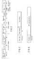
- FIG. 2 is a view showing the structure of a PPPoE data link frame.
- protocol type is 8863h for the discovery stage and 8864h for the session stage.
- Code represents the type of packet in the discovery stage.
- 09h represents a PADI (PPPoE Active Discovery Initiator) packet; 07h, a PADO (PPPoE Active Discovery Offer) packet; 19h, a PADR (PPPoE Active Discovery Request) packet; 65h, a PADS (PPPoE Active Discovery Session-confirmation) packet; and a7h, a PADT (PPPoE Active Discovery Terminate) packet.
- Code "00h” represents the PPP session stage.
- Session ID is sent from an access concentrator to a client, and used in the PPP session stage.
- the PPPoE payload of the discovery stage contains 0 or a plurality of tags.
- One tag is made up of the type, length, and value, and defined as follows.
- Tag type represents the type of tag. For example, 0101h represents a Service-Name tag; and 0102h, an AC-Name tag.
- FIG. 4 shows the PPPoE payload of the PPP session stage.
- the protocol and PPP payload are the same as those used in a PPP data link frame.
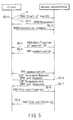
- the client When a client is to start the PPPoE stage, the client first executes the discovery stage in order to identify the Ethernet MAC address of a peer and establish a PPPoE session ID.
- the client broadcasts a PADI (PPPoE Active Discovery Initiator) packet (S0-1).
- PADI PPoE Active Discovery Initiator
- S0-1 PIPoE Active Discovery Initiator
- a requested service name can be set in the Service-Name tag, but the Service-Name tag is generally null.
- the access concentrator unicasts (to be simply referred to as "transmit” hereinafter) a PADO (PPPoE Active Discovery Offer) packet as a response to the client.
- PADO PPPoE Active Discovery Offer
- the client transmits a PADR (PPPoE Active Discovery Request) packet as a PPP connection request (S0-3).
- PADR PPPoE Active Discovery Request
- S0-3 PPP connection request
- the remote side has only one access concentrator which responds to the PADI, but when the client receives a plurality of PADO packets, it selects one access concentrator to be connected.
- the access concentrator generates a session ID and transmits a PADS (PPPoE Active Discovery Session-confirmation) packet (S0-4). After that, the discovery stage ends.
- PADS PPoE Active Discovery Session-confirmation
- the client and access concentrator perform PPP communication (S0-5: PPP session stage).
- the client transmits Terminate-Request by a PPP LCP (Link Control Protocol) packet as an end request (S0-6).
- PPP LCP Link Control Protocol
- the access concentrator transmits Terminate-Ack by a PPP LCP packet as an end acknowledgement to end the PPP session (S0-7).
- the client ends the PPP session and transmits a PADT (PPPoE Active Discovery Terminate) packet to end the PPPoE session (S0-8).
- PADT PPPoE Active Discovery Terminate
- the access concentrator transmits a PADT (PPPoE Active Discovery Terminate) packet to end the PPPoE session (S0-9).
- PADT PPPoE Active Discovery Terminate
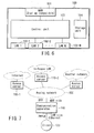
- FIG. 6 is a block diagram showing the communication apparatus according to the first embodiment of the present invention.
- a communication apparatus 100 is a bridge device having one dial-up-connectable WAN interface 101 such as an analog modem, TA (Terminal Adapter), or RS-232C interface, and LAN interfaces 102-1 to 102-N such as an Ethernet interface, wireless LAN interface, and the like.
- dial-up-connectable WAN interface 101 such as an analog modem, TA (Terminal Adapter), or RS-232C interface
- LAN interfaces 102-1 to 102-N such as an Ethernet interface, wireless LAN interface, and the like.
- a control unit 103 controls dial-up connection of the WAN interface 101, relays packets between the LAN interfaces 102-1 to 102-N, and relays packets between the LAN and the WAN.
- a storage unit 104 stores information necessary to control or relay the interfaces.
- FIG. 7 is a view showing an example of constituting a system by using the communication apparatus 100 according to the first embodiment of the present invention.
- the communication apparatus 100 has one LAN interface 102 which is an Ethernet device, and the dial-up-connectable WAN interface 101 is an analog modem.
- the analog modem 101 can be connected to an ISP (Internet Service Provider) remote access server 110-1, in-house LAN remote access server 110-2, and the like via an analog line 150.
- the Ethernet interface 102 is connected to a client 120 via an Ethernet cable.
- the communication apparatus has a PPPoE access concentrator function.
- a client is connected to the communication apparatus by using a PPPoE, and the communication apparatus is connected to a remote access server by using dial-up connection (line connection and PPP connection).
- communication is performed using the PPPoE between the client and the communication apparatus, and the PPP between the communication apparatus and the remote access server.
- the communication apparatus mutually converts and relays the PPPoE and PPP packets.
- one remote access server communicates with one client via the discovery stage and PPP session stage.
- a client in the present invention communicates with the communication apparatus in the discovery stage and the remote access server in the PPP session stage.
- the communication apparatus establishes dial-up connection with the remote access server during the discovery stage.
- the communication apparatus performs dialing, so that the client must notify the communication apparatus of the telephone number of a connection destination. This is achieved by setting telephone number information in the Service-Name tag.
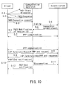
- connection, communication, and disconnection sequences of the communication apparatus according to the first embodiment of the present invention will be explained with reference to FIG. 10.
- the client sets the telephone number of a remote access server at a connection destination in the Service-Name tag, and broadcasts a PADI (PPPoE Active Discovery Initiator) packet (S-1).
- PADI PPoE Active Discovery Initiator
- the communication apparatus unicasts (to be simply referred to as "transmit” hereinafter) a PADO (PPPoE Active Discovery Offer) packet as a response to the client.
- PADO PPPoE Active Discovery Offer
- the client transmits a PADR (PPPoE Active Discovery Request) packet as a PPP connection request (S-3).
- the communication apparatus dials the remote access server at the connection destination via a WAN interface (analog modem) by using the received telephone number (S-4), thereby establishing line connection with the remote access server (S-5).
- the communication apparatus generates a session ID and transmits a PADS (PPPoE Active Discovery Session-confirmation) packet (S-6). Then, the discovery stage ends, and the processing shifts to the PPP session stage.
- PADS PPPoE Active Discovery Session-confirmation
- the client and remote access server communicate with each other by the PPP via the communication apparatus (S-7).
- the communication apparatus In the PPP session stage, the communication apparatus only mutually converts (to be described later) and transfers PPPoE and PPP packets.
- the client transmits Terminate-Request by a PPP LCP packet as an end request (S-8).
- the remote access server transmits Terminate-Ack by a PPP LCP packet as an end acknowledgement to end the PPP session (S-9).
- the client ends the PPP session and transmits a PADT (PPPoE Active Discovery Terminate) packet to end the PPPoE session (S-10). Thereafter, the communication apparatus disconnects the line (S-11).
- PADT PPPoE Active Discovery Terminate
- the communication apparatus transmits a PADT (PPPoE Active Discovery Terminate) packet to end the PPPoE session (S-12).
- PADT PPPoE Active Discovery Terminate
- FIG. 8 shows the structure of a PPP data link frame
- FIG. 9 shows the structure of a PPPoE data link frame in the PPP session stage.
- a packet is transferred from the LAN to the WAN as follows.
- the communication apparatus Upon reception of a packet of a protocol type "8864h" from the LAN-side port, the communication apparatus determines that the packet is one in the PPPoE session stage. The communication apparatus checks the session ID to confirm that the session ID has the same value as that sent from the communication apparatus by a PADS packet.
- the communication apparatus converts the packet.
- the communication apparatus checks an FCS to confirm that the data frame is correct.
- the communication apparatus recalculates the FCS, adds it to the end of the PPP, and transmits the resultant packet to the WAN side.
- a packet is transferred from the WAN to the LAN as follows.
- This protocol conversion enables communication in the PPP session stage.
- the communication apparatus can select an arbitrary remote access server on the basis of an instruction from a client, and dial-up-connect the client to the remote access server without setting any connection method in the communication apparatus in advance.
- An LCP/NCP (Network Control Protocol) negotiation can also be directly communicated between the client and the remote access server.
- the client is connected as if it were PPPoE-connected to the remote access server.
- PPPoE client software can be applied to WAN connection.
- the remote access server is connected as if it were dial-up-connected to the client.
- the client can, therefore, communicate with a conventional remote access server without any special setting.
- a client device having no dial-up connection interface can be dial-up-connected as far as it has a LAN interface (Ethernet, wireless LAN, or the like).
- FIG. 11 is a block diagram showing the communication apparatus according to the second embodiment of the present invention.
- a communication apparatus 200 is a router having one dial-up-connectable WAN interface 201 such as an analog mode, TA (Terminal Adapter), or RS-232C interface, and LAN interfaces 202-1 to 202-N such as an Ethernet interface, wireless LAN interface, and the like.
- a control unit 203 controls dial-up connection of the WAN interface, relays packets between the LAN interfaces, and relays and routes packets between the LAN and the WAN.
- a storage unit 204 stores information necessary for routing and filtering.
- FIG. 12 is a view showing an example of constituting a system by using the communication apparatus 200 according to the second embodiment of the present invention. As shown in FIG. 12, the communication apparatus 200 has two LAN interfaces.
- the dial-up-connectable WAN interface 201 is a TA and can be connected to an ISP (Internet Service Provider) remote access server 210-1, in-house LAN remote access server 210-2, and the like via an ISDN line 250.
- ISP Internet Service Provider
- the LAN interface 202-1 is an Ethernet interface and is connected to a client 220-1 via an Ethernet cable.
- the LAN interface 202-2 is an IEEE 802.11 wireless LAN interface and is wirelessly connected to two clients 220-2 and 220-3.
- the communication apparatus has two, router and bridge modes. In a normal state, the communication apparatus operates in the router mode.
- FIG. 13 is a logical block diagram for explaining the function of the router mode
- FIG. 14 is a logical block diagram for explaining the function of the bridge mode.
- a relay unit 203-1 relays packets between the LAN interfaces. If necessary, a routing unit 203-2 performs dial-up connection to a remote access server via a WAN interface to route packets between the LAN interface and the WAN interface.
- the communication apparatus When the communication apparatus receives a PPPoE connection request (packet of a protocol type "8863h") from an arbitrary client, the apparatus shifts to the bridge mode via the PPPoE discovery stage.
- a PPPoE connection request packet of a protocol type "8863h”
- the relay unit 203-1 relays packets between the LAN interfaces, but the routing unit stops its function.
- a bridge unit 203-3 dial-up-connects the communication apparatus to a remote access server by using the WAN interface 201.
- the bridge unit 203-3 converts a PPPoE packet received from the LAN interface into a PPP packet, and relays the PPP packet to the WAN interface (to the contrary, converts a PPP packet received from the WAN interface into a PPPoE packet, and relays the PPPoE packet to the LAN interface).
- FIG. 14 shows an example in which the Ethernet interface 202-1 and TA 201 are bridge-connected to each other.
- a packet transferred from the LAN interface 202-1 to the bridge unit 203-3 is only a PPPoE packet (packets of protocol types "8863h” and "8864h"), and other packets are transferred to the relay unit 203-1.
- the Ethernet interface 202-1 and control unit 203 are connected by two lines in order to explain a logical function, but are physically connected by one line. After PPP connection is canceled, the communication apparatus returns to the router mode.
- connection, communication, and disconnection sequences of the communication apparatus according to the second embodiment of the present invention will be explained with reference to FIG. 10.
- the operation of the communication apparatus according to the second embodiment of the present invention is basically the same as that of the first embodiment, and only a difference will be described.
- the communication apparatus is not intended for the router function. If a client issues a PPP connection request, the communication apparatus executes dial-up connection in S4 by using a telephone number received from the client.
- the communication apparatus stops routing operation upon reception of a PADR packet as a PPP connection request from the client.
- the communication apparatus temporarily cancels it and shifts from the router mode to the bridge mode.
- the communication apparatus dials a remote access server from the WAN interface by using the received telephone number, and performs line connection.
- the communication apparatus transmits a PADT (PPPoE Active Discovery Terminate) packet in S-12. After the PPPoE session ends, i.e., disconnection processing is completed, the communication apparatus shifts to the router mode. If necessary, the communication apparatus performs dial-up connection in the router mode again.
- PADT PPPoE Active Discovery Terminate
- the communication apparatus of the second embodiment can be used as a dial-up router in a normal state, and if necessary, directly dial-up-connect a client to another remote access server.
- the communication apparatus is very convenient particularly when a notebook model PC with a wireless LAN function is to be connected to both the Internet and an in-house LAN.
- This communication apparatus realizes such a use form that the PC is always connected to the Internet via a FLET'S ISDN or the like in a normal state such as home use, and dial-up-connected to the in-house LAN as needed.
- FIG. 15 is a block diagram showing the arrangement of a communication apparatus according to the third embodiment of the present invention.
- a communication apparatus 300 is a router having two WAN interfaces 301, and one or a plurality of LAN interfaces 302 such as an Ethernet interface, wireless LAN interface, and the like.
- One of the WAN interfaces 301 is a dial-up-connectable WAN interface such as an analog modem, TA (Terminal Adapter), RS-232C interface, or the like.
- the other is a WAN interface connectable to an ADSL, cable television, ISDN dedicated line, or the like (or may be a dial-up-connectable WAN interface).
- a control unit 303 controls dial-up connection of the WAN interface, relays packets between the LAN interfaces, and relays and routes packets between the LAN and the WAN.
- a storage unit 304 stores information necessary for routing and filtering.
- FIG. 16 is a view showing an example of constituting a system by using the communication apparatus 300.
- the communication apparatus 300 has three LAN interfaces.
- a WAN interface 301-1 is an RS-232C interface, and can be connected to an in-house LAN remote access server 310-1 or the like via a TA 360 and ISDN line 350.
- a WAN interface 301-2 is an ADSL modem and is always connected to an ISP (Internet Service Provider) remote access server 310-2 via a telephone line. Both LAN interfaces 302-1 and 302-2 are Ethernet interfaces, and are respectively connected to clients 320-1 and 320-2 via Ethernet cables.
- a LAN interface 302-3 is an IEEE 802.11 wireless LAN interface and is wirelessly connected to a client 320-3.
- the communication apparatus has two, router and router/bridge modes. In a normal state, the communication apparatus operates in the router mode.
- FIG. 17 is a logical block diagram for explaining the function of the router mode
- FIG. 18 is a logical block diagram for explaining the function of the router/bridge mode.
- the communication apparatus uses not the WAN interface (RS-232C) 301-1 but only the WAN interface (ADSL modem) 301-2.
- a relay unit 303-1 relays packets between the LAN interfaces, and a routing unit 303-2 routes packets between the LAN interface and the WAN interface (ADSL modem) 301-2.
- the communication apparatus When the communication apparatus receives a PPPoE connection request (packet of a protocol type "8863h") from an arbitrary client, the apparatus shifts to the router/bridge mode via the PPPoE discovery stage.
- a PPPoE connection request packet of a protocol type "8863h”
- a bridge unit 303-3 dial-up-connects the communication apparatus to a remote access server by using the TA 360 via the RS-232C interface 301-1, similar to the first embodiment.
- the bridge unit 303-3 converts a PPPoE packet received from the LAN interface into a PPP packet, and relays the PPP packet to the WAN interface.
- the bridge unit 303-3 converts a PPP packet received from the WAN interface into a PPPoE packet, and relays the PPPoE packet to the LAN interface.
- FIG. 18 shows an example in which the Ethernet interface 302-1 and RS-232C interface 301-1 are bridge-connected to each other.
- a packet transferred from the LAN interface 302-1 to the bridge unit 303-3 is only a PPPoE packet (packets of protocol types "8863h” and "8864h"), and other packets are transferred to the relay unit 303-1.
- Ethernet interface 302-1 and control unit 303 are connected by two lines in order to explain a logical function, but are physically connected by one line. After PPP connection is canceled, the communication apparatus returns to the router mode.
- the operation of the communication apparatus according to the third embodiment of the present invention is basically the same as that of the first embodiment, and only a difference will be described.
- the communication apparatus is not intended for the router function. If a client issues a PPP connection request, the communication apparatus executes dial-up connection in S4 by using a telephone number received from the client.
- the communication apparatus shifts from the router mode to the router/bridge mode upon reception of a PADR packet as a PPP connection request from the client.
- the communication apparatus dials a remote access server from the WAN interface (RS-232C interface) 301-1 by using the received telephone number, and performs line connection.
- WAN interface RS-232C interface
- the communication apparatus transmits a PADT (PPPoE Active Discovery Terminate) packet in S-12. After the PPPoE session ends, i.e., disconnection processing is completed, the communication apparatus shifts to the router mode.
- PADT PPPoE Active Discovery Terminate
- the communication apparatus of the third embodiment can be used as a broadband router in a normal state, and if necessary, directly dial-up-connect a client to another remote access server.
- the communication apparatus is very convenient especially when a notebook model PC with a wireless LAN function is to be connected to both the Internet and an in-house LAN.
- This communication apparatus realizes such a use form that the PC is always connected to the Internet via an ADSL, cable television, or the like in a normal state such as home use, and dial-up-connected to the in-house LAN as needed.
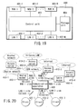
- FIG. 19 is a block diagram showing the arrangement of a communication apparatus according to the fourth embodiment of the present invention.
- a communication apparatus 400 is a router having two or more WAN interfaces 401, and one or a plurality of LAN interfaces 402 such as an Ethernet interface, wireless LAN interface, and the like.
- At least one of the WAN interfaces 401 is a dial-up-connectable WAN interface such as an analog modem, TA (Terminal Adapter), RS-232C interface, or the like.
- a control unit 403 controls dial-up connection of the WAN interface, relays packets between the LAN interfaces, and relays and routes packets between the LAN and the WAN.
- a storage unit 404 stores information necessary for routing and filtering in addition to the following setting information:
- the control unit 403 executes packet routing/relay and dial-up connection on the basis of these pieces of setting information.
- the use of WAN interfaces except WAN_A and WAN_B is stopped.
- FIG. 20 is a view showing an example of constituting a system by using the communication apparatus according to the fourth embodiment of the present invention.
- the communication apparatus 400 has two dial-up-connectable WAN interfaces, two other WAN interfaces, and three LAN interfaces.
- a dial-up-connectable WAN interface 401-1 is an RS-232C interface, and can be connected to a remote access server 410-1 via an analog modem 460-1 and analog line 450-1.
- a dial-up-connectable WAN interface 401-2 is a TA and can be connected to a remote access server 410-2 via an ISDN line 450-2.
- a WAN interface 401-3 is an ADSL modem and is always connected to a remote access server 410-3 via a telephone line.
- a WAN interface 401-4 is an Ethernet interface and is always connected to a remote access server 410-4 of a cable television company via a cable modem 460-4.
- a LAN interface 402-1 is an IEEE 802.11 wireless LAN and is wirelessly connected to a client 420-1.
- a LAN interface 402-2 is an Ethernet interface and is connected to a client 420-2 via an Ethernet cable.
- a LAN interface 402-3 is a USB interface and is connected to a client 420-3 via a USB cable.
- dial-up-connectable WAN interfaces are the WAN interfaces 401-1 and 401-2, and WAN_A is selected from them.
- WAN_B is selected from the four WAN interfaces 401-1 to 401-4.
- WAN_A and WAN_B are identical WAN interfaces, only one WAN Interface is used. Thus, the router and bridge modes are switched in accordance with a PPPoE connection request, similar to the second embodiment.
- WAN_A and WAN_B are different WAN interfaces, two WAN Interfaces can be used.
- the router and router/bridge modes are switched in accordance with a PPPoE connection request, similar to the third embodiment.
- FIG. 21 is a logical block diagram in the router mode when both WAN_A and WAN_B are the WAN interfaces (TA) 401-2.
- FIG. 22 is a logical block diagram in the bridge mode.
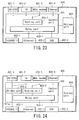
- FIG. 23 is a logical block diagram in the router mode when WAN_A is the WAN interface 401-2 and WAN_B is the WAN interface 401-3 (ADSL modem).
- FIG. 24 is a logical block diagram in the router/bridge mode.
- Connection, communication, and disconnection operations upon reception of a PPPoE connection request, and a packet conversion method are the same as those in the second and third embodiments, and a description thereof will be omitted.
- the communication apparatus of the fourth embodiment can freely set a WAN interface to be router-connected to the LAN and a WAN interface to be bridge-connected to the LAN.
- a telephone number to be dialed is sent by the Service-Name tag.
- the telephone number may be designated by the alphabet or the like instead of directly designating it in Service-Name.
- a correspondence table of service names and telephone numbers is set in the communication apparatus, and searched for a target telephone number.
- Service-Name may be kept null, and a default telephone number may be set and used in the communication apparatus.
- RFC 2516 describes only PPPoE in a case in which a PPP packet is transmitted "by the Ethernet"
- PPPoE can also be properly used in an IEEE 802.11 wireless LAN.
- an IEEE 802.2 SNAP data frame is used, and PPPoE can be used by an IEEE 802.2 device.
- Usable LAN devices in addition to an IEEE 802.11 device are a token bus, token ring, FDDI, Bluetooth, and the like.
- the communication apparatus may transmit an Echo_Request packet to a client at any time in the PPP session stage of PPPoE in order to confirm whether a link with the client has been established. In this case, Echo_Reply from the client is not transferred to the WAN side.
- Echo_Request is received from the WAN side (no Echo_Request is generally received in the case of a telephone line)
- the communication apparatus sends back Echo_Reply. To cope with this function, the communication apparatus must check every PPP packet (PPPoE packet in the PPP session stage) which is simply converted and transferred in the above embodiments.
- control unit of the communication apparatus comprises an Echo_Request packet transmission unit and packet check unit.
- the Echo_Request packet transmission unit transmits an Echo_Reply packet at a predetermined timing to a client and receives Echo_Reply from the client.
- the packet check unit determines whether the communication apparatus has received an Echo_Request packet from the WAN side, and if determining that the communication apparatus has received the Echo_Request packet, sends back Echo_Reply corresponding to the received Echo_Request packet.
- the communication apparatus can respond to an inquiry about whether a link has been established, from an access server in the PPP session stage.
- the communication apparatus can respond to an inquiry from a client.
- the "communication apparatus” may be implemented as a portable telephone (or PHS) with a wireless LAN function, and a wireless LAN PC may be dial-up-connected via the portable telephone.
- PHS portable telephone
- a wireless LAN PC may be dial-up-connected via the portable telephone.
- the present invention is not limited to the above-described embodiments, and can be variously modified without departing from the spirit and scope of the invention in practical use.
- the respective embodiments can be combined as properly as possible. In this case, the effects of the combination can be obtained.
- the embodiments include inventions on various stages, and various inventions can be extracted by an appropriate combination of building components disclosed. For example, when an invention is extracted by omitting several building components from all those described in the embodiments, the omission is properly compensated for by a well-known technique in practicing the extracted invention.
- the present invention can provide a communication apparatus with a dial-up function that can bridge-connect a client device to a WAN at an arbitrary timing with arbitrary settings (telephone number and the like) without changing router settings.
- the present invention can provide a communication apparatus with a dial-up function that can realize router connection and dial-up connection to the WAN by connecting a router and PC only via a LAN (Ethernet, wireless LAN, or the like).
- a LAN Ethernet, wireless LAN, or the like.
Landscapes
- Engineering & Computer Science (AREA)
- Computer Networks & Wireless Communication (AREA)
- Signal Processing (AREA)
- Data Exchanges In Wide-Area Networks (AREA)
- Small-Scale Networks (AREA)
- Telephonic Communication Services (AREA)
Abstract
Description
Claims (10)
- A communication apparatus with a dial-up function, characterized by comprising:a first interface (102-1) which can connect a communication terminal;a second interface (101) which is connected to a plurality of dial-up-connectable servers; andconnection means (103), when a connection request to a server connected to said second interface is received from the communication terminal connected to said first interface, configured to connect the communication terminal to the server at a connection request destination via said second interface on the basis of information representing the server at the connection request destination sent from the communication terminal.
- An apparatus according to claim 1, characterized by further comprising conversion means for performing protocol conversion processing between a protocol in a FIRST connected to said first interface and a protocol in a WAN connected to said second interface.
- An apparatus according to claim 2, characterized in that sad conversion means performs routing processing between a LAN connected to the first interface and a WAN connected to the second interface.
- An apparatus according to claim 1, characterized by further comprising:means for determining whether a first packet used to confirm that connection between the communication terminal and the server is not canceled is received; andmeans for sending back, to a transmission source of the first packet, a second packet representing that connection between the communication terminal and the server is not canceled when said determination means determines that the first packet is received.
- An apparatus according to claim 1, characterized in that said first interface includes a plurality of first interfaces, which further comprises routing means for performing routing processing between LANs connected to said plurality of first interfaces, and in which when information representing a connection request destination is received from the communication terminal during routing processing by said routing means, said connection means stops the routing processing and dial-up-connects the communication terminal to a server at a connection destination via said second interface.
- An apparatus according to claim 1, characterized in that said first interface includes a plurality of first interfaces, which further comprises a third interface, and routing means for performing routing processing between LANs connected to said plurality of first interfaces, and routing processing between a WAN connected to said third interface and a LAN connected to said first interface, and in which when information representing a connection request destination is received from the communication terminal during routing processing by said routing means, said connection means connects the communication terminal to a server at a connection destination via said second interface.
- A communication apparatus characterized by comprising:a LAN interface;a first WAN interface which is connected to a dial-up-connectable server; andconversion means for performing protocol conversion processing between a protocol in a LAN connected to said LAN interface and a protocol in a WAN connected to said first WAN interface.
- An apparatus according to claim 7,
characterized in that the protocol in the LAN includes PPP, and the protocol in the WAN includes PPPoE. - A communication method in a communication apparatus having a LAN interface, and a first WAN interface which is connected to a dial-up-connectable server, comprising:receiving information representing a server at a connection request destination from a communication terminal connected to the LAN interface; anddial-up-connecting the communication terminal to the server at the connection request destination via the first WAN interface on the basis of the received information representing the server at the connection request destination.
- A method according to claim 9, characterized in that communication between the server and the communication terminal is achieved by performing protocol conversion processing between a protocol in a WAN connected to the first WAN interface and a protocol in a LAN connected to the LAN interface after connection between the server and the communication terminal is established.
Applications Claiming Priority (2)
| Application Number | Priority Date | Filing Date | Title |
|---|---|---|---|
| JP2002015876A JP3692083B2 (en) | 2002-01-24 | 2002-01-24 | Communication device with dial-up function |
| JP2002015876 | 2002-01-24 |
Publications (2)
| Publication Number | Publication Date |
|---|---|
| EP1331774A2 true EP1331774A2 (en) | 2003-07-30 |
| EP1331774A3 EP1331774A3 (en) | 2004-06-02 |
Family
ID=19191976
Family Applications (1)
| Application Number | Title | Priority Date | Filing Date |
|---|---|---|---|
| EP02026587A Withdrawn EP1331774A3 (en) | 2002-01-24 | 2002-11-28 | Communication apparatus with dial-up function |
Country Status (3)
| Country | Link |
|---|---|
| US (1) | US20030137985A1 (en) |
| EP (1) | EP1331774A3 (en) |
| JP (1) | JP3692083B2 (en) |
Cited By (1)
| Publication number | Priority date | Publication date | Assignee | Title |
|---|---|---|---|---|
| WO2006034662A1 (en) * | 2004-09-30 | 2006-04-06 | Siemens Aktiengesellschaft | System for nomadic data access from subscriber terminal devices, devices in said system and data access method |
Families Citing this family (16)
| Publication number | Priority date | Publication date | Assignee | Title |
|---|---|---|---|---|
| US20040141511A1 (en) * | 2002-12-23 | 2004-07-22 | Johan Rune | Bridging between a bluetooth scatternet and an ethernet LAN |
| US7400647B1 (en) * | 2003-01-13 | 2008-07-15 | Extreme Networks | Look up table (LUT) for point-to-point protocol identification (PPP ID) |
| JP2005064783A (en) * | 2003-08-11 | 2005-03-10 | Nec Corp | Public internet connection service system and access line connection device |
| CN100435520C (en) * | 2004-09-02 | 2008-11-19 | 上海贝尔阿尔卡特股份有限公司 | Methods of choosing services offered by different network service providers |
| JP2006148726A (en) * | 2004-11-24 | 2006-06-08 | Nec Infrontia Corp | Communication system, terminal, access line concentrator selection method used therefor, and program thereof |
| JP4655903B2 (en) * | 2004-12-08 | 2011-03-23 | 株式会社日立製作所 | Packet transfer device |
| US20060280189A1 (en) * | 2005-06-13 | 2006-12-14 | Mcrae Matthew | Residential gateway discovery |
| US8804696B1 (en) * | 2006-11-07 | 2014-08-12 | At&T Intellectual Property Ii, L.P. | Integrated gateway |
| US20080159302A1 (en) * | 2006-12-30 | 2008-07-03 | Arcsoft (Shanghai) Technology Company, Ltd | Network Communication Equipment with PPPoE Bridging Function |
| JP4576409B2 (en) * | 2007-08-08 | 2010-11-10 | パナソニック株式会社 | COMMUNICATION LINE CONTROL DEVICE, COMMUNICATION LINE CONTROL METHOD, PROGRAM, AND RECORDING MEDIUM |
| CN102377623B (en) * | 2010-08-24 | 2014-11-19 | 国基电子(上海)有限公司 | User terminal and method for establishing dial-up connection |
| JP5496371B2 (en) * | 2011-01-25 | 2014-05-21 | アラクサラネットワークス株式会社 | Network relay system and network relay device |
| EP3338435A1 (en) * | 2015-08-18 | 2018-06-27 | Thomson Licensing | Methods and apparatuses for providing addressability to devices in a network |
| JP2017200105A (en) * | 2016-04-28 | 2017-11-02 | Necプラットフォームズ株式会社 | Information distribution device |
| CN111492631B (en) * | 2017-12-21 | 2023-05-16 | 村田机械株式会社 | Communication system control method, communication system, and relay device |
| US11005907B2 (en) * | 2018-12-19 | 2021-05-11 | Intel Corporation | Single stream format for multiple display modes |
Family Cites Families (6)
| Publication number | Priority date | Publication date | Assignee | Title |
|---|---|---|---|---|
| US6377571B1 (en) * | 1998-04-23 | 2002-04-23 | 3Com Corporation | Virtual modem for dialout clients in virtual private network |
| US5953345A (en) * | 1998-06-02 | 1999-09-14 | Cisco Technology, Inc. | Reduced pin-count 10Base-T MAC to transceiver interface |
| DE19833069A1 (en) * | 1998-07-22 | 2000-01-27 | Siemens Ag | Terminal device-to-exchange modem connection method via local networks |
| US6829235B1 (en) * | 1999-02-19 | 2004-12-07 | Nokia Networks Oy | Telecommunications network with parallel session function |
| US6674756B1 (en) * | 1999-02-23 | 2004-01-06 | Alcatel | Multi-service network switch with multiple virtual routers |
| CN100337461C (en) * | 2000-03-17 | 2007-09-12 | 美国在线服务公司 | System and method for home networking |
-
2002
- 2002-01-24 JP JP2002015876A patent/JP3692083B2/en not_active Expired - Lifetime
- 2002-11-28 EP EP02026587A patent/EP1331774A3/en not_active Withdrawn
- 2002-12-17 US US10/320,613 patent/US20030137985A1/en not_active Abandoned
Cited By (1)
| Publication number | Priority date | Publication date | Assignee | Title |
|---|---|---|---|---|
| WO2006034662A1 (en) * | 2004-09-30 | 2006-04-06 | Siemens Aktiengesellschaft | System for nomadic data access from subscriber terminal devices, devices in said system and data access method |
Also Published As
| Publication number | Publication date |
|---|---|
| JP3692083B2 (en) | 2005-09-07 |
| US20030137985A1 (en) | 2003-07-24 |
| JP2003218948A (en) | 2003-07-31 |
| EP1331774A3 (en) | 2004-06-02 |
Similar Documents
| Publication | Publication Date | Title |
|---|---|---|
| US8751617B2 (en) | Method and device for identifying and selecting an interface to access a network | |
| US7733859B2 (en) | Apparatus and method for packet forwarding in layer 2 network | |
| JP3692083B2 (en) | Communication device with dial-up function | |
| US7376123B2 (en) | Management and control of call center and office telephony assets | |
| US6377571B1 (en) | Virtual modem for dialout clients in virtual private network | |
| JP3836272B2 (en) | Movement point-to-point protocol | |
| US7542476B2 (en) | Method and system for manipulating IP packets in virtual private networks | |
| US6542935B1 (en) | Method for obtaining a second address free from association with multiple devices | |
| CN101119252B (en) | Access network system, access device, ARP proxy method and IP bridging and forwarding method | |
| WO2003075517A2 (en) | Setup for customer premise equipment (cpe) with ppp bridge using the same public ip address at the wan side and the lan side | |
| JP2003333080A (en) | Method for transitioning between link systems and mobile computing device | |
| JP4425923B2 (en) | Access service network system, access device, and access service providing method | |
| JP2007104440A (en) | Packet transmission system, its method, and tunneling device | |
| US7738434B1 (en) | Control and management of a wired or wireless headset | |
| CN101202720B (en) | Method for establishing gateway equipment and method for processing data of gateway equipment | |
| JPH10117215A (en) | Method and apparatus for connecting between networks | |
| GB2374256A (en) | Method and apparatus for providing network access for PDA devices | |
| US20040258056A1 (en) | Provider connection system, packet exchange apparatus thereof, dns server, packet exchange method, and computer program thereof | |
| EP1445896A1 (en) | Provider connection system, packet exchange apparatus thereof, dns server, packet exchange method, and computer program thereof | |
| JP4817797B2 (en) | PPPoE bridge device and PPPoE session disconnection method | |
| US20080259932A1 (en) | Method and System for Facilitating a First and Second Protocol Between a Data Processing System and an ISP | |
| JP3896300B2 (en) | Communication device having IPv4 / IPv6 dual stack function | |
| EP1180893B1 (en) | Modem device | |
| JP2004228878A (en) | Network connection device and method | |
| JP5322875B2 (en) | COMMUNICATION METHOD, COMMUNICATION DEVICE, AND COMMUNICATION SYSTEM |
Legal Events
| Date | Code | Title | Description |
|---|---|---|---|
| PUAI | Public reference made under article 153(3) epc to a published international application that has entered the european phase |
Free format text: ORIGINAL CODE: 0009012 |
|
| 17P | Request for examination filed |
Effective date: 20021128 |
|
| AK | Designated contracting states |
Designated state(s): AT BE BG CH CY CZ DE DK EE ES FI FR GB GR IE IT LI LU MC NL PT SE SK TR |
|
| AX | Request for extension of the european patent |
Extension state: AL LT LV MK RO SI |
|
| PUAL | Search report despatched |
Free format text: ORIGINAL CODE: 0009013 |
|
| AK | Designated contracting states |
Kind code of ref document: A3 Designated state(s): AT BE BG CH CY CZ DE DK EE ES FI FR GB GR IE IT LI LU MC NL PT SE SK TR |
|
| AX | Request for extension of the european patent |
Extension state: AL LT LV MK RO SI |
|
| RIC1 | Information provided on ipc code assigned before grant |
Ipc: 7H 04L 12/28 B Ipc: 7H 04L 12/64 A |
|
| 17Q | First examination report despatched |
Effective date: 20040727 |
|
| AKX | Designation fees paid |
Designated state(s): DE FR GB |
|
| 17Q | First examination report despatched |
Effective date: 20040727 |
|
| STAA | Information on the status of an ep patent application or granted ep patent |
Free format text: STATUS: THE APPLICATION IS DEEMED TO BE WITHDRAWN |
|
| 18D | Application deemed to be withdrawn |
Effective date: 20080530 |