The present invention relates to an electronic
apparatus using a fuel cell, such as a portable
electronic apparatus.
In recent years, it is proposed to use a fuel cell
in a notebook personal computer (hereinafter referred
to as notebook PC), which is an example of a personal
electronic apparatus. The fuel cell is advantageous in
that it can produce power unlimitedly as long as it is
fueled.
Cell batteries of various types are known, and a
DMFC (direct methanol fuel cell) is one of the known
types. The DMFC is a fuel cell which uses methanol as
its liquid fuel (methanol is comparatively low in price
and is easy to handle).
In general, a DMFC comprises the following: a fuel
tank which contains a high concentration of methanol; a
mixing tank in which the methanol supplied from the
fuel tank is diluted with water; a liquid-supply pump
which supplies the methanol diluted in the mixing tank
toward the anode of a fuel cell panel; and an air-supply
pump which supplies air toward the cathode of
the fuel cell panel.
When supplied with the methanol and air, the fuel
cell panel generates power between the anode and the
cathode. At the time, the anode and the cathode
produce carbon dioxide and water, respectively.
The carbon dioxide produced by the anode and the
water produced by the cathode are returned to the
mixing tank. Of these, the water is used for diluting
the methanol supplied from the fuel tank. An extra
amount of water is turned into vapor and discharged
from the mixing tank together with the carbon dioxide.
The fuel cell is provided inside the main body of
the notebook PC. Where the fuel cell is provided
inside the main body, the vapor-containing carbon
dioxide discharged from the mixing tank of the fuel
cell may condense on the main board in the main body or
on electronic components (e.g., a CPU) provided on the
main board. Such condensation is undesirable because
it adversely affects the performance required of the
electronic components.
The present invention is to provide an electronic
apparatus wherein vapor exhausted from the fuel cell is
prevented from condensing on electronic components
inside the main body.
According to one aspect of the present invention,
there is provided an electronic apparatus comprising:
According to the electronic apparatus described
above, the vapor-containing gas generated from the fuel
cell is discharged from the main body by the cooling
fan provided for the main body.
This summary of the invention does not necessarily
describe all necessary features so that the invention
may also be a sub-combination of these described
features.
The invention can be more fully understood from
the following detailed description when taken in
conjunction with the accompanying drawings, in which:
Embodiments of the present invention will now be
described with reference to the accompanying drawings.
FIGS. 1 through 5 illustrate the first embodiment
of the present invention.
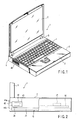
FIG. 1 shows a notebook PC 1, which is an example
of a portable electronic apparatus. The notebook PC 1
comprises a hollow main body 2. A palm rest 3 is
formed on the front portion of the main body 2, and a
keyboard 4 is located behind the palm rest 3.
A pair of hinges are provided on the rear portion
of the upper surface of the main body 2. A liquid
crystal display 6 is rotatably coupled to the main body
2 by means of the hinges.
As FIG. 5 shows, a power supply section 11 is
located inside the main body 2. The power supply
section 11 is powered by an AC adaptor 13 connected
to an AC connector 12. The AC connector 12 is
provided, for example, on the rear face of the main
body 2.
The power supply section 11 can be powered not
only by the AC adaptor 13 described above but also by a
secondary battery pack 14 and a fuel cell 15, both
incorporated in the main body 2. A changeover switch
(not shown) determines which element, the AC adaptor
13, the battery pack 14 or the fuel cell 15, is used
for applying power to the power supply section 11.
The power supply section 11 applies power to a
main board 16 including electronic components. A CPU
17 is mounted on the main board 16. A modem 15, a DVD
19, etc. are connected to the main board 16.
A DMFC, which uses methanol as a liquid fuel, is
employed as the fuel cell 15. As FIGS. 2 and 3 show,
the fuel cell 15 comprises a casing 21 that can be
received inside the main board 2. As FIG. 3 shows, a
fuel tank 22 is disposed inside the casing 21, and the
fuel tank 22 contains a high concentration of methanol
used as a liquid fuel. The fuel tank 22 is connected
to a mixing tank 23, and a first liquid-supply pump 24
supplies the methanol from the fuel tank 22 to the
mixing tank 23.
The methanol supplied to the mixing tank 23 is
diluted with water, which functions as a solvent and is
supplied from a pair of fuel cell panels 25 to be
described later. A second liquid-supply pump 26 is
connected to the mixing tank 23. By the second liquid-supply
pump 26, the diluted methanol is supplied toward
the anodes of the fuel cell panels 25 through a liquid-supply
pipe 27.
In the initial state, the mixing tank 23 contains
diluted methanol, and the two fuel cell panels 25 also
contain diluted methanol. Therefore, water (i.e., a
solvent) does not have to be supplied to the mixing
tank 23.
The liquid-supply pipe 27 includes a main pipe
portion 27a and a pair of branch pipe portions 27b.
The main pipe portion 27a has its one end connected to
the outlet portion of the second liquid-supply pump 26.
The branch pipe portions 27b are symmetric with respect
to the other end of the main pipe portion 27a. In
FIG. 3, the branch pipe portions 27b are shown as being
connected to the upper side portion of the fuel cell
panels 25.
As indicated by the dashed lines in FIG. 3, each
of the two fuel cell panels 25 is rectangular. Two
fuel cell panels 25 are arranged side by side and are
held by two holding plates 28 (only one of which is
shown) in such a manner that the upper and lower
surfaces are in contact with the holding plates 28.
The two holding plates 28 are secured by means of a
plurality of fastening screws 30 located on the
peripheral portions of the fuel cell panels 25.
The present embodiment employs two fuel cell
panels 25, and these panels 25 are held between the
holding plates 28. In comparison with the case where a
single fuel cell panel is employed, the holding force
is uniformly distributed onto the entire surfaces of
the fuel cell panels, and the fuel cell panels 25 are
allowed to maintain their desirable performance.
The liquid-supply pipe 27 has one end connected to
the second liquid-supply pump 26 and the other end
connected to the two branch pipe portions 27b. Through
these branch pipe portions, the liquid-supply pipe 27
is connected to the fuel cell panels 25. In comparison
with the case where the two fuel cells 25 are
individually connected to piping, the overall length of
the piping can be reduced. In addition, the paired
fuel cell panels 25 can be supplied with a liquid fuel
under the same condition.
An air-supply pump 29 supplies air through an air-supply
tube 31 to the cathode of each fuel cell panel
25. The methanol and air supplied to each fuel cell
panel 25 react in an electrolyte film, which is located
between the anode and the cathode.
This reaction generates power between the anode
and the cathode. Simultaneously, carbon dioxide is
produced from the anode, and water is produced from the
cathode. The carbon dioxide produced from the anode is
supplied to the mixing tank 23 by way of the corresponding
one of discharge-liquid tubes 33. On the
other hand, the water produced from the cathode is
supplied through the corresponding one of discharge-gas
tubes 32 into the mixing tank 23 in the state of vapor.
The mixing tank 23 has a discharge section 34 that
allows only gas to pass therethrough. The discharge
section 34 is open in the upper surface of the casing
21 of the fuel cell 15. The carbon dioxide and the
vapor returned into the mixing tank 23 by way of the
discharge-liquid tubes 33 and discharge-gas tubes 32,
are discharged from the discharge section 34.
As FIGS. 2 and 4 show, a cooling fan 41 is
provided inside the main body 2 of the notebook PC 1.
The cooling fan 41 cools the electronic components,
including CPU 17. The cooling fan 41 includes an inlet
41a (i.e., a suction section) and an outlet 41b (i.e.,
a discharge or delivery section). The inlet 41a is
opposed to an air take-in port 42 formed in the back
face of the main body 2, and the outlet 41b is opposed
to an air discharge port 43 formed in a side surface of
the main body 2. The air take-in port 42 and the
discharge port 43 are comparatively close to each other
(the air take-in port 42 in the back face and the
discharge port 43 in the side surface are close to the
same corner of the main body 2).
The fuel cell 15 is disposed inside the main body
2 in such a manner that the discharge section 34 of the
mixing tank 23 is opposed to the discharge port 43
formed in the main body 2. In the present embodiment,
the discharge section 34 is located between the outlet
41b of the cooling fan 41 and the discharge port 43 of
the main body 2. FIG. 4 shows only the mixing tank 23
of the fuel cell 15, which is disposed inside the main
body 2.
When the notebook PC 1 is used at places where the
AC adapter 13 is not available, the changeover switch
(not shown) provided for the main body 2 is operated so
that the power supply section 11 is driven by the fuel
cell 15.
Upon operation of the changeover switch, the fuel
cell 15 is actuated, methanol, which has been supplied
from the fuel tank 22 to the mixing tank 23 and diluted
with water, is supplied to the fuel cell panel 25. In
addition, air is supplied to the fuel cell panel 25 by
the air-supply pump 29. As a result, the methanol and
the air react with each other in the electrolyte film
of the fuel cell panel 25. Power, thus generated
between the anode and the cathode, is applied to the
power supply section 11.
When the fuel cell 15 is actuated, carbon dioxide
is generated from the anode, while water is generated
from the cathode. The carbon dioxide and the water are
returned to the mixing tank 23. The carbon dioxide
returned to the mixing tank 23 is discharged into the
interior of the main body 2 through the discharge
section 34 of the mixing tank 23 in the state where the
carbon dioxide contains vapor.
The discharge section 34 is opposed to the
discharge port 43 of the main body 2. The cooling fan
41 has its outlet 41b opposed to the discharge port 43.
The cooling fan 41 is turned on in response to an
operation of the notebook PC 1.
When the cooling fan 41 is turned on, air is
sucked into the interior of the main body 2 through the
air take-in port 42 of the main body 2, as shown in
FIG. 4. Air is also introduced into the interior
through another air take-in port (not shown). Then,
the air is blown out from the outlet 41b of the cooling
fan 41, passes through the region above the discharge
section 34 of the mixing tank 23, and is discharged
from the main body 2 through the discharge port 43.
The CPU 17 and other electronic devices are cooled
by the air that flows inside the main body 2 in the
manner described above. It should be noted that the
air introduced into the interior of the main body 2 and
blown out from the outlet 41b of the cooling fan 41
passes through the region above the discharge section
34 of the mixing tank 23 and is then discharged from
the main body 2 through the discharge section 34.
Owing to this feature, the vapor-containing carbon
dioxide from the discharge section 34 is discharged
from the main body through the discharge port 43,
together with the air.
In other words, as soon as the vapor-containing
carbon dioxide is discharged into the main body 2 from
the discharge section 34 of the mixing tank 23, the
cooling fan 41 discharges that carbon dioxide from the
main body 2 through the discharge port 43 of the main
body 2 without allowing the carbon dioxide to stay in
the main body 2. Hence, the carbon dioxide is not
diffused inside the main body 2 and therefore does not
flow toward the electronic-device portions of the main
board 16.
For this reason, the vapor contained in the carbon
dioxide is prevented from condensing on the main body
16 or on the CPU 17 or other electronic devices mounted
on the main body 16.
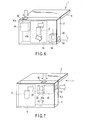
FIG. 6 shows the second embodiment of the present
invention. The second embodiment is similar to the
first embodiment in that the discharge section 34 of
the mixing tank 23 is opposed to the discharge port 43
of the main body 2. In the second embodiment, however,
the discharge port 43 is located at the front portion
of one side wall of the main body 2, and the air take-in
port 42 in the rear wall of the main body 2 is
diagonally opposite to the discharge port 43. In other
words, the discharge port 43 and the air take-in port
42 is at positions far away from each other.
The cooling fan 41 has its inlet 41a opposed to
the air take-in port 42 and its outlet 41b directed
toward the main board 16, which is located between the
cooling fan 41 and the mixing tank 23.
When the cooling fan 41 is turned on, air is drawn
into the interior of the main body 2 from the air take-in
port 42. After cooling the main board 16 and the
CPU 17 and other electronic devices mounted on the main
board 16, the air passes through the region above the
mixing tank 23. Then, the air is discharged from the
main body 2.
In the second embodiment, the discharge section 34
of the mixing tank 23 is opposed to the discharge port
43 of the main body 2. With this structure, the vapor-containing
carbon dioxide which is to be discharged
from the discharge port 43 is not diffused in the main
body 2. It does not flow toward the CPU 17 or other
electronic devices arranged inside the main body 2, let
alone condense on them.
FIG. 7 shows the third embodiment of the present
invention. In the third embodiment, the air take-in
port 42 formed in the rear surface of the main body 2
and the discharge port 43 formed in one side surface of
the main body 2 are comparatively close to each other.
They are comparatively close to one corner of the main
body 2. The cooling fan 41 is disposed in the main
body 2 in such a manner that its outlet 41b is opposed
to the discharge port 43. The mixing tank 23 is
located between the inlet 41a of the cooling fan 41 and
the air take-in port 42. The discharge section 34 of
this mixing tank 23 is opposed to the air take-in
section 42. The main board 16 on which the CPU 17 is
mounted is located in the right half region of the main
body 2, i.e., in the region where the discharge port 43
is not provided.
When the cooling fan 41 is turned on, air is drawn
into the interior of the main body 2 from the air take-in
port 42. Although not shown, the main body 2 has
other air take-in ports as well. Because of the
formation of those air take-in ports, the air streams
indicated by the arrows in FIG. 7 are produced.
The air introduced into the main body 2 flows
toward the inlet 41a of the cooling fan 41. Since the
discharge section 34 of the mixing tank 23 is also
opposed to the inlet 41a, not only the air introduced
into the main body 2 but also the vapor-containing
carbon dioxide discharged from the discharge section 34
of the mixing tank 23 is also sucked into the discharge
section 34 of the mixing tank 23. In this manner, the
air and the vapor-containing carbon dioxide are
discharged from the outlet 41b of the cooling fan 41.
Hence, they are not diffused inside the main body 2.
In the third embodiment as well, the vapor-containing
carbon dioxide discharged from the mixing
tank 23 of the fuel cell 15 can be discharged without
allowing it to pass through the regions where
electronic devices, including the main board 16 of the
main body 2, are provided. Hence, the vapor does not
condense on the electronic devices.
In the above descriptions of the first to third
embodiments, reference was made to the case where the
fuel cell 15 was disposed inside the main body 2 of the
notebook PC 1. In this case, the fuel tank 22, the
mixing tank 23, the fuel cell panel 25 and other
structural components of the fuel cell 15 need not be
integrally provided as one body; they may be disposed
at predetermined positions inside the main body
separately from one another.
This structure enhances the degree of freedom with
which the structural components are arranged. Hence,
the mixing tank 23 can be easily disposed at the
position shown in each of the first to third
embodiments.
FIGS. 8 through 10 show the fourth to sixth
embodiments of the present invention, respectively. In
these embodiments, the fuel cell 15 is provided on the
outer surface of the bottom of the main body 2 of the
notebook PC 1. The structural components of the fuel
cell 15 are disposed inside the casing 21 in the same
manner as in the first embodiment described with
reference to FIG. 3, and the casing 21 containing
these components is provided on the bottom of the main
body 2.
In the fourth embodiment shown in FIG. 8, a vapor-introducing
port 46 is formed in the bottom surface of
the main body 2 in such a manner that the port 46 is
close to one side surface of the main body 2. Through
this port 46, the vapor-containing carbon dioxide
discharged from the discharge section 34 of the mixing
tank 23 of the fuel cell is introduced into the
interior of the main body 2. When the bottom surface
of the main body 2 is placed on the upper surface of
the casing 21 of the fuel cell 15, the discharge
section 34 is opposed to the vapor-introducing port 46.
A cooling fan 41 is disposed inside the main body
2 in such a manner that its outlet 41b is opposed to
the discharge port 43. The vapor-introducing port 46
described above is located between the outlet 41b and
the discharge port 43. The inlet 41a of the cooling
fan 41 is directed to the air take-in port 42 formed in
the rear surface of the main body 2. The main board 16
on which the CPU 17 is mounted is located in the right
half region of the main body 2, i.e., in the region
where the vapor-introducing port 46 is not provided.
When the cooling fan 41 is turned on, air is drawn
into the interior of the main body 2 from the air take-in
port 42. In the main body 2, the air is sucked into
the inlet 41a of the cooling fan 41 and flows out of
the outlet 41b. The air is discharged from the
discharge port 43 to which the outlet 41b is opposed.
When the fuel cell is used, vapor-containing
carbon dioxide is discharged from the discharge section
34 of the mixing tank 23 of the fuel cell. The carbon
dioxide enters the main body 2 from the vapor-introducing
port 46 formed in the bottom of the main
body 2 and opposed to the discharge section 34.
Thereafter, the vapor-containing carbon dioxide is
discharged from the discharge port 43 of the main body
2, together with the air discharged from the outlet 41b
of the cooling fan 41.
When the fuel cell 15 is placed on the lower
surface of the main body 2, the vapor-containing carbon
dioxide discharged from the upper surface of the casing
of the fuel cell 15 becomes a problem. The present
embodiment solves this problem by guiding the carbon
dioxide from the vapor-introducing port 46 formed in
the bottom of the main body 2 to the outlet 41b of the
cooling fan 41 of the main body 2 and discharging the
carbon dioxide from the discharge port 43 together with
air.
As can be seen from this, even where the fuel cell
15 is provided on the outer surface of the bottom of
the main body 2 of the notebook PC 1, the vapor-containing
carbon dioxide generated by the fuel cell
can be discharged reliably by means of the cooling fan
41 provided in the main body 2. In addition, the
vapor-containing carbon dioxide can be discharged
without making it pass through the regions where the
CPU 17 or other electronic devices are provided.
Hence, no condensation is caused on the electronic
devices.
FIG. 9 shows the fifth embodiment of the present
invention. In the fifth embodiment, an air take-in
port 42 is formed in the rear surface of the main body
2 in such a manner that it is close to the right end of
the main body 2. The inlet 41a of the cooling fan 41
is opposed to the air take-in port 42.
A discharge port 43 is formed in one side surface
of the main body 2 in such a manner that it is located
close to the front surface. The vapor-introducing port
46 is formed in the bottom on the main body 2 in such a
manner that it is located close to the discharge port
43. The main board 16 on which the CPU 17 is mounted
is located between the vapor-introducing port 46 and
the outlet 41b of the cooling fan 41.
When the main body 2 is placed on the upper
surface of the casing 21, the discharge section 34 of
the mixing tank 23 is opposed to the vapor-introducing
port 46.
When the cooling fan 41 is turned on, air is drawn
into the interior of the main body 2 from the air take-in
port 42. In the main body 2, the air output from
the outlet 41b of the cooling fan 41 cools the CPU 17
mounted on the main board 16, and is then discharged
from the main body 2 through the discharge port 43.
Before being discharged from the discharge port
43, the air flows through the region above the
vapor-introducing port 46. From this port 46, the
vapor-containing carbon dioxide generated by the fuel
cell 15 is introduced into the main body 2. The carbon
dioxide is therefore discharged from the discharge port
53 together with the air described above.
Like the fourth embodiment shown in FIG. 8, the
fifth embodiment does not diffuse the vapor-containing
carbon dioxide inside the main body 2. To be more
specific, the vapor-containing carbon dioxide generated
by the fuel cell 15 and introduced into the main body 2
of the notebook PC 1 is not diffused inside the main
body 2. Because of the operation of the cooling fan
41, the vapor-containing carbon dioxide can be
discharged from the discharge port 43, without being
diffused in the main body 2 and without passing through
the region where the CPU 17 is provided.
Although the vapor-containing carbon dioxide is
made to pass through the region inside the main body 2
because of the operation of the cooling fan 41, the
vapor does not condense on the electronic devices
(e.g., CPU 17) arranged inside the main body 2.
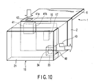
FIG. 10 shows the sixth embodiment of the present
invention. The sixth embodiment is similar to the
fifth embodiment shown in FIG. 9 in light of the
structure of the main body 2 of the notebook PC 1. In
the sixth embodiment, however, the vapor-introducing
port 46 is not formed in the bottom of the main body 2,
and the discharge port 43 is formed instead.
The casing 21 of the fuel cell 15 has a hollow
section 48 which is open in both the upper surface and
one side surface of the casing 21. The discharge
section 34 of the mixing tank 23 provided inside the
casing 21 is formed in the bottom of the hollow section
48. When the main body 2 is laid on the upper surface
of the casing 21 of the fuel cell 15, the discharge
section 34 is opposed to the discharge port 43. The
discharge section 34 is open in the bottom surface of
the hollow section 48, and is located away from the
hollow section 48 by a predetermined distance.
When the cooling fan 41 is turned on, air is drawn
into the interior of the main body 2 from the air take-in
port 42. In the main body 2, the air cools the main
board 16 and the CPU 17 mounted thereon, and is then
discharged from the main body 2 through the discharge
port 43 and through the hollow section 48 of the casing
21 of the fuel cell 15.
On the other hand, the vapor-containing carbon
dioxide is discharged into the hollow section 48 from
the discharge section 34 of the mixing tank 23 of the
fuel cell 15. The carbon dioxide is then guided out of
the hollow section 48 by the cooling fan 41, along with
the gasses flowing out from the discharge port 43 of
the main body 2.
As can be seen from the above, the sixth
embodiment does not permit the vapor-containing carbon
dioxide generated by the fuel cell 15 to enter the main
body. The carbon dioxide is guided in a predetermined
direction by the cooling fan 41 and discharged
reliably.