EP1331650A2 - Method and associated apparatus for reducing the tension of wires during a strand production process - Google Patents
Method and associated apparatus for reducing the tension of wires during a strand production process Download PDFInfo
- Publication number
- EP1331650A2 EP1331650A2 EP03075183A EP03075183A EP1331650A2 EP 1331650 A2 EP1331650 A2 EP 1331650A2 EP 03075183 A EP03075183 A EP 03075183A EP 03075183 A EP03075183 A EP 03075183A EP 1331650 A2 EP1331650 A2 EP 1331650A2
- Authority
- EP
- European Patent Office
- Prior art keywords
- wire
- speed
- roller
- pulling
- wires
- Prior art date
- Legal status (The legal status is an assumption and is not a legal conclusion. Google has not performed a legal analysis and makes no representation as to the accuracy of the status listed.)
- Granted
Links
- 238000000034 method Methods 0.000 title claims abstract description 24
- 238000004519 manufacturing process Methods 0.000 title claims abstract description 7
- 238000004804 winding Methods 0.000 claims abstract description 35
- 239000003638 chemical reducing agent Substances 0.000 description 2
- 239000004020 conductor Substances 0.000 description 2
- 238000010586 diagram Methods 0.000 description 2
- 230000000694 effects Effects 0.000 description 2
- 230000002093 peripheral effect Effects 0.000 description 2
- 230000001105 regulatory effect Effects 0.000 description 2
- 230000002542 deteriorative effect Effects 0.000 description 1
- 238000012986 modification Methods 0.000 description 1
- 230000004048 modification Effects 0.000 description 1
- 238000003908 quality control method Methods 0.000 description 1
Images
Classifications
-
- H—ELECTRICITY
- H01—ELECTRIC ELEMENTS
- H01B—CABLES; CONDUCTORS; INSULATORS; SELECTION OF MATERIALS FOR THEIR CONDUCTIVE, INSULATING OR DIELECTRIC PROPERTIES
- H01B13/00—Apparatus or processes specially adapted for manufacturing conductors or cables
- H01B13/02—Stranding-up
- H01B13/0285—Pretreatment
Definitions
- the present invention relates to a method and an associated apparatus for reducing the tension of wires during a process for production of a strand using said wires.
- said strands are made from a wire or a plurality of wires wound onto a supply reel from which the wire(s) is/are unwound so as to be fed to the stranding machine which forms the bundles of wires, imparts one or more twists to them and winds the strand thus formed onto a take-up reel.
- the wire is however subject to slackening and/or tensioning and, in order to compensate for this, the supply reel is equipped with an arm for adjusting the unwinding speed; said arm has a roller onto which the wire is wound and is connected to means for adjusting the speed of rotation of the said reel.
- the wire is subject to a tension in the longitudinal direction which is permitted and regulated within certain limits, since it tends to equalize the behaviour of different wires wound onto the same reel and wires wound onto different reels.
- the technical problem which is posed, therefore, is that of providing an apparatus which allows a reduction in the tension produced on the wire during winding thereof onto a reel, for example of a stranding machine.
- a method for reducing the tension of wires during a process for production of a strand using said wires comprising the steps of: unwinding at least one wire from a supply reel, feeding the unwound wire to a stranding machine which pulls the wire, winding it onto a take-up reel at a predetermined winding speed, said at least one wire being subject to a pulling/pushing action in the same sense as the direction of feeding thereof, along the section of the travel path between the supply reel and the point of entry into the stranding machine.
- the present invention also relates to an apparatus for reducing the tension of wires during a process for forming a strand wound onto a reel of a stranding machine using at least one wire fed from a supply reel, which apparatus comprises means able to impart to said at least one wire a pulling/pushing force in the same sense as the direction of feeding of the said wire, along the section of the travel path of the wire between the supply reel and the point of entry into the stranding machine.
- a conventional plant for forming a strand 2 from at least one wire 1 comprises essentially a reel 10 for supplying the wire(s) 1, a device 20 for guiding the wire(s) entering a stranding machine, schematically shown together with the associated winding reel 30.
- the guiding device schematically shown is of the type able to impart a single twist to the wire, but, although not illustrated, the stranding machine may comprise means able to impart a double twist to the wires before they are wound onto the reel 30.
- the supply reel 10 is connected to an arm 11 for adjusting its speed of rotation, which arm is in turn connected to the wires being unwound.
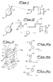
- Fig. 2 shows the plant according to Fig. 1 equipped with an apparatus 100 for reducing the tension of the wires to which the wires 1 are subject during the process for forming and winding a strand 2, which apparatus is arranged in a position between the supply reel 10 and the point of entry into the stranding machine in the direction of feeding of the wires 1.
- the apparatus according to the invention will also be called a tension-reducing apparatus.
- the tension-reducing apparatus 100 is substantially formed by a first roller 111 which is motorized and by a second drive roller 112 which is idle, the wires 1 being made to pass between said rollers.
- the first motorized roller 111 is rotated by means of an associated controlled motor 111a which imparts a speed of rotation of the roller such as to produce a peripheral speed which is slightly greater than the driving speed of the stranding machine.
- the motor 111a is also connected to a speed control device 120, for example of the type called "encoder", onto which one of the wires 1 fed to the stranding machine is wound; said device is able to detect the speed of the roller and send corresponding signals to actuating means able to vary the speed of rotation of the motor 111a and therefore the corresponding roller 111.
- a speed control device 120 for example of the type called "encoder”
- the second idle roller 112 is mounted on an associated frame 112a which is movable translationwise parallel to the direction of feeding of the wires 1 so as to produce a relative position of the two rollers 111,112 such as to allow adjustment of the winding angle of the said wires 1 around the first motorized roller as illustrated in Figs. 4a to 4c where a winding angle of 90° is modified to a winding angle of about 180°.
- the second roller 112 is in turn motorized by means of a motor 111b which is also regulated by the encoder signal and imparts to the second roller 112 a speed of rotation which is substantially the same as that of the first roller 111 and therefore slightly greater than the speed of feeding of the wire.
- the tension-reducing effect is substantially determined by the winding angle on the first motorized (or active) roller - or by the sum of the winding angles on all the active rollers - it follows that, for the same reduction in tension on the wires 1, the motorization of the second roller 112 results in winding angles of the wires on the two active rollers which are smaller than those required in the case of an idle second roller, also allowing the mechanical design of the apparatus to be simplified.
- a method for reducing the longitudinal tension of wires 1 forming the components of a strand 2 to be wound onto a reel 30 of a stranding machine is also defined, said method envisaging the following steps:
- said pulling/pushing action is obtained by means of application of a sliding friction to the wire; said sliding friction being determined by the pulling/pushing action of a roller on which the wire is wound at a predefined winding angle depending on the characteristics of the wire and the strand to be formed.
- Said winding angle is normally between 60° and 300° and preferably between 90° and 240°.
- the roller which applies the pulling/pushing force to the wire is rotationally actuated so as to have a speed slightly greater than the speed of driving of the wire by the stranding machine.
- the peripheral speed of the roller is greater than the speed of driving of the wire by an amount ranging between 2% and 10% of the latter.
Landscapes
- Engineering & Computer Science (AREA)
- Manufacturing & Machinery (AREA)
- Ropes Or Cables (AREA)
- Wire Processing (AREA)
- Processes Specially Adapted For Manufacturing Cables (AREA)
Abstract
Description
- Figure 1 shows a functional diagram of a plant of the conventional type for forming a strand;
- Figure 2 shows a diagram similar to that of Fig. 1 with an apparatus for reducing the tension of the wire, according to the present invention;
- Figure 3 shows a view of an example of embodiment of the tension-reducing apparatus according to the present invention; and
- Figures 4a-4c show schematic views of examples of differently adjusted arrangements of a second embodiment of the apparatus according to the invention.
- unwinding at least one wire 1 from a supply reel;
- feeding the unwound wire 1 to a stranding machine which pulls the wire, winding it onto a take-up reel 31 at a predefined winding speed;
| PARAMETER | WITH TENSION-REDUCER | WITHOUT TENSION-REDUCER |
| Elongation of wires (%) | 20.8 | 13.6 |
| Electrical resistance (ohm/kg) | 1.74 | 1.84 |
Claims (28)
- Method for reducing the tension of wires during a process for production of a strand using said wires, comprising the steps of:characterized in that said at least one wire is subjected to a pulling/pushing action in the same sense as the direction of feeding thereof, along the section of the travel path between the supply reel and the point of entry into the stranding machine.unwinding at least one wire (1) from a supply reel;feeding the unwound wire (1) to a stranding machine which pulls the wire, winding it onto a take-up reel (31) at a predetermined winding speed;
- Method according to Claim 1, characterized in that said pulling/pushing action is obtained by means of application of a sliding friction to the wire.
- Method according to Claim 2, characterized in that said sliding friction is determined by the pulling/pushing action of at least one motorized roller on which the wire is wound at a predefined winding angle.
- Method according to Claim 2, characterized in that said sliding friction is determined by the pulling/pushing action of a pair of motorized rollers on which the wire is wound at a predefined winding angle.
- Method according to Claim 3, characterized in that said winding angle is between 60° and 300°.
- Method according to Claim 5, characterized in that said winding angle is preferably between 90° and 240°.
- Method according to Claim 3, characterized in that the roller which applies the pulling/pushing action to the wire is rotationally actuated so as to have a speed greater than the speed of driving of the wire by the stranding machine.
- Method according to Claim 3, characterized in that the speed of rotation of the motorized roller is greater than the speed of driving of the wire by an amount ranging between 2% and 10% of the latter.
- Apparatus for reducing the tension of the wires (1) during a process for forming a strand (2) wound onto a reel (30) of a stranding machine using at least one wire (1) fed from a supply reel (10,11), characterized in that it comprises means (111,112) able to impart to said at least one wire (1) a pulling/pushing action in the same sense as the direction of feeding of the said wire, along the section of the travel path between the supply reel (10,11) and the winding reel (30).
- Apparatus according to Claim 9, characterized in that said pulling/pushing means comprise at least one first roller (111) which is motorized and able to impart said pushing/pulling action and a second drive roller (112) which is idle, the wires (1) being wound around said rollers.
- Apparatus according to Claim 9, characterized in that said pushing means comprise at least one first motorized roller (111) able to impart said pushing/pulling action and at least one second motorized roller (112), around which rollers the wires (1) are wound.
- Apparatus according to Claim 10 or 11, characterized in that said first and second rollers are parallel to each other.
- Apparatus according to Claim 10 or 11, characterized in that said second roller (112) is movable translationwise relative to the first roller (111).
- Apparatus according to Claim 10, characterized in that said first motorized roller (111) is rotated at a speed of rotation greater than the winding speed of the reel (30) of the stranding machine.
- Apparatus according to Claim 14, characterized in that the speed of rotation of the motorized roller (111) is greater than the speed of driving of the wire (1) by an amount preferably ranging between 2% and 10% of the latter.
- Apparatus according to Claim 11, characterized in that said first motorized roller (111) is rotated at a speed of rotation greater than the winding speed of the stranding machine and said second motorized roller (112) is rotated at a speed substantially the same as that of the first roller.
- Apparatus according to Claim 10, characterized in that it comprises a device (120) for controlling the speed of rotation of the motorized roller(s) on which one of the wires (1) fed to the stranding machine (30) is wound.
- Apparatus according to Claim 17, characterized in that said control device (120) is able to detect the speed of the roller and send corresponding signals to actuating means able to vary the speed of rotation of the motor (111a, 111b) for actuating the motorized roller(s).
- Apparatus according to Claim 1, characterized in that the angle of winding of the wire (1) around the motorized roller(s) is between 60° and 300°.
- Plant for forming strands (2) from wires (1), in which at least one stranding machine with a winding reel (30) and at least one reel (10,11) for feeding at least one wire (1) are envisaged, characterized in that it comprises an apparatus for reducing the tension of said at least one wire (1), which is provided with means (111,112) able to impart to said at least one wire (1) a pulling/pushing action in the same sense as the direction of feeding of the said wire, along the section of the travel path of the wire between the supply reel (10,11) and the winding reel (30).
- Plant according to Claim 20, characterized in that said pushing/pulling means of the apparatus comprise at least one first roller (111) which is motorized and able to impart said pushing/pulling action and one second drive roller (112) which is idle, the wires (1) being wound around said rollers.
- Plant according to Claim 21, characterized in that said pushing/pulling means of the apparatus comprise at least one first motorized roller (111) able to impart said pushing/pulling action and at least one second motorized roller (112), around which rollers the wires (1) are wound.
- Plant according to Claim 21, characterized in that said first motorized roller (111) is rotated at a speed of rotation greater than the winding speed of the stranding machine.
- Plant according to Claim 23, characterized in that the speed of rotation of the motorized roller (111) is greater than the speed of driving of the wire (1) by an amount ranging between 2% and 10% of the latter.
- Plant according to Claim 22, characterized in that said first motorized roller (111) is rotated at a speed of rotation greater than the winding speed of the stranding machine and said second motorized roller (112) is rotated at a speed substantially the same as that of the first roller.
- Plant according to Claim 21, characterized in that it comprises a device (120) for controlling the speed of rotation of the motorized roller(s) on which one of the wires (1) fed to the stranding machine (30) is wound.
- Plant according to Claim 26, characterized in that said control device (120) is able to detect the speed of the roller(s) and send corresponding signals to actuating means able to vary the speed of rotation of the motor (111a,112b) actuating the motorized roller(s).
- Plant according to Claim 21, characterized in that the winding angle of the wire (1) around the motorized roller(s) is between 60° and 300°.
Applications Claiming Priority (2)
| Application Number | Priority Date | Filing Date | Title |
|---|---|---|---|
| IT2002MI000120A ITMI20020120A1 (en) | 2002-01-24 | 2002-01-24 | METHOD AND RELATED EQUIPMENT FOR DETENSIONING OF WIRES DURING A ROPE PRODUCTION PROCESS |
| ITMI20020120 | 2002-01-24 |
Publications (4)
| Publication Number | Publication Date |
|---|---|
| EP1331650A2 true EP1331650A2 (en) | 2003-07-30 |
| EP1331650A3 EP1331650A3 (en) | 2003-12-03 |
| EP1331650B1 EP1331650B1 (en) | 2010-07-28 |
| EP1331650B8 EP1331650B8 (en) | 2010-09-01 |
Family
ID=11448973
Family Applications (1)
| Application Number | Title | Priority Date | Filing Date |
|---|---|---|---|
| EP03075183A Expired - Lifetime EP1331650B8 (en) | 2002-01-24 | 2003-01-20 | Method and associated apparatus for reducing the tension of wires during a strand production process |
Country Status (5)
| Country | Link |
|---|---|
| US (1) | US20030141400A1 (en) |
| EP (1) | EP1331650B8 (en) |
| AT (1) | ATE475973T1 (en) |
| DE (1) | DE60333509D1 (en) |
| IT (1) | ITMI20020120A1 (en) |
Families Citing this family (2)
| Publication number | Priority date | Publication date | Assignee | Title |
|---|---|---|---|---|
| CN105047319B (en) * | 2015-08-25 | 2017-03-08 | 安吉腾飞电子有限公司 | A kind of stranded winding device of electric wire |
| US10934142B2 (en) * | 2018-02-27 | 2021-03-02 | Hall Labs Llc | Motor-driven fairlead for assisting spooling or unspooling from a winch |
Family Cites Families (21)
| Publication number | Priority date | Publication date | Assignee | Title |
|---|---|---|---|---|
| US2127936A (en) * | 1935-11-29 | 1938-08-23 | Nat Standard Co | Wire winding apparatus |
| US2985393A (en) * | 1956-03-12 | 1961-05-23 | Glanzstoff Ag | Winding machine for the production of bobbins with predetermined thread tension overthe bobbin run |
| US3526368A (en) * | 1968-06-10 | 1970-09-01 | Deering Milliken Res Corp | Method and apparatus for winding thread |
| GB1235439A (en) * | 1969-06-18 | 1971-06-16 | Standard Telephones Cables Ltd | An arrangement for controlling the acceleration and tension of strip material being unwound from a spirally wound pad |
| US4212422A (en) * | 1978-09-18 | 1980-07-15 | Rca Corporation | Web position controller for web transport systems |
| JPS57144633A (en) * | 1981-03-05 | 1982-09-07 | Inoue Japax Res Inc | Wire electrode feeder |
| SE463667B (en) * | 1987-11-03 | 1991-01-07 | Profor Ab | UNROLLING DEVICE CONSIDERING TEMPORARY MATERIALS INCLUDING A BRAKE DEVICE CONTROLLED BY THE POSITION TENSION |
| JPH01209139A (en) * | 1988-02-18 | 1989-08-22 | Tokyo Kikai Seisakusho Ltd | Guide roller apparatus in rotary press |
| JPH0227623A (en) * | 1988-07-18 | 1990-01-30 | Sumitomo Wiring Syst Ltd | Manufacturing method and device for compressed conductor |
| US4958111A (en) * | 1989-09-08 | 1990-09-18 | Gago Noel J | Tension and web guiding system |
| JPH0629112B2 (en) * | 1990-10-08 | 1994-04-20 | 株式会社東京機械製作所 | Angle bar device |
| JP2909294B2 (en) * | 1992-03-16 | 1999-06-23 | 日東グラスファイバー工業株式会社 | Method for producing glass yarn |
| EP0606731B1 (en) * | 1992-12-25 | 1997-08-06 | ISHIDA CO., Ltd. | Apparatus for correcting zigzag motion of an elongated travelling web |
| JP3346254B2 (en) * | 1997-05-09 | 2002-11-18 | 住友電気工業株式会社 | Optical fiber |
| DE29720235U1 (en) * | 1997-11-14 | 1998-01-22 | Océ Printing Systems GmbH, 85586 Poing | Device for transporting and temporarily storing a web-shaped record carrier in an electrographic printing or copying device |
| US6199787B1 (en) * | 1998-03-02 | 2001-03-13 | Asif Jaffar | Method of transferring individual ends of yarns from a beam to individual cones |
| DE19824798A1 (en) * | 1998-06-03 | 1999-12-09 | Indag Gmbh & Co Betriebs Kg | Device and method for feeding foils |
| FR2781717B1 (en) * | 1998-07-29 | 2000-10-20 | Darlet Marchante Technologies | DEVICE FOR AUTOMATICALLY FEEDING A SYNTHETIC FILM TAPE INTO A CROSS-DRAWING MACHINE |
| US6352257B1 (en) * | 1999-08-30 | 2002-03-05 | Asterisk, Inc. | Web stabilizer |
| JP3382196B2 (en) * | 2000-01-05 | 2003-03-04 | 株式会社東京機械製作所 | Web paper position adjustment device |
| US6467511B2 (en) * | 2000-07-06 | 2002-10-22 | Miliken & Company | Selvage yarn tensioning apparatus and method |
-
2002
- 2002-01-24 IT IT2002MI000120A patent/ITMI20020120A1/en unknown
-
2003
- 2003-01-20 DE DE60333509T patent/DE60333509D1/en not_active Expired - Lifetime
- 2003-01-20 AT AT03075183T patent/ATE475973T1/en not_active IP Right Cessation
- 2003-01-20 EP EP03075183A patent/EP1331650B8/en not_active Expired - Lifetime
- 2003-01-22 US US10/349,124 patent/US20030141400A1/en not_active Abandoned
Also Published As
| Publication number | Publication date |
|---|---|
| ITMI20020120A1 (en) | 2003-07-24 |
| EP1331650B1 (en) | 2010-07-28 |
| EP1331650A3 (en) | 2003-12-03 |
| ITMI20020120A0 (en) | 2002-01-24 |
| US20030141400A1 (en) | 2003-07-31 |
| EP1331650B8 (en) | 2010-09-01 |
| ATE475973T1 (en) | 2010-08-15 |
| DE60333509D1 (en) | 2010-09-09 |
Similar Documents
| Publication | Publication Date | Title |
|---|---|---|
| EP2150643B1 (en) | Method of folding filament and bundle of filament manufactured thereof | |
| KR101803182B1 (en) | Electromagnetic wave shielding cable manufacturing apparatus | |
| CA2235170A1 (en) | Apparatus for helically assembling at least two filaments | |
| KR101775826B1 (en) | Improved productivity electromagnetic wave shielding cable manufacturing apparatus | |
| EP1331650B1 (en) | Method and associated apparatus for reducing the tension of wires during a strand production process | |
| KR101803238B1 (en) | Improved productivity electromagnetic wave shielding cable manufacturing apparatus | |
| JPH10244339A (en) | Stranded wire manufacturing equipment | |
| JP4263076B2 (en) | Method and apparatus for manufacturing steel wire rubber composite material | |
| JP4375283B2 (en) | Manufacturing method and manufacturing apparatus of extra fine stranded wire | |
| KR101803236B1 (en) | Improved productivity electromagnetic wave shielding cable manufacturing apparatus | |
| KR100409222B1 (en) | Apparatus for maintaining constant tension of externally provided wire of steel cord type strander | |
| JP2888127B2 (en) | Wire feeding supply device | |
| KR101803237B1 (en) | Improved productivity electromagnetic wave shielding cable manufacturing apparatus | |
| JP2994628B1 (en) | Stranded wire device | |
| KR20050000712A (en) | Apparatus for producing a stranded cable including tension controlling means | |
| EP0396068B1 (en) | Method and apparatus for making a bundle of wires or a cable | |
| CN209777977U (en) | Automatic control wire releasing device and wire winding and releasing device for anti-shrinkage wires | |
| JP3560818B2 (en) | Tape winding flat conductor guide device and composite tape winding device | |
| US4509317A (en) | Apparatus and method for making metallic cord | |
| JP2596348Y2 (en) | Straightening device in twisting machine | |
| JPH10147470A (en) | Stranded wire device | |
| JPH07105754A (en) | Electric wire feeder | |
| JP2000144588A (en) | Method and apparatus for twisting multi-layer twisted steel cord | |
| JP2897123B2 (en) | Twisting method and device using buncher twisting machine | |
| JPH10109822A (en) | Fishing line winding device |
Legal Events
| Date | Code | Title | Description |
|---|---|---|---|
| PUAI | Public reference made under article 153(3) epc to a published international application that has entered the european phase |
Free format text: ORIGINAL CODE: 0009012 |
|
| AK | Designated contracting states |
Designated state(s): AT BE BG CH CY CZ DE DK EE ES FI FR GB GR HU IE IT LI LU MC NL PT SE SI SK TR |
|
| AX | Request for extension of the european patent |
Extension state: AL LT LV MK RO |
|
| PUAL | Search report despatched |
Free format text: ORIGINAL CODE: 0009013 |
|
| AK | Designated contracting states |
Kind code of ref document: A3 Designated state(s): AT BE BG CH CY CZ DE DK EE ES FI FR GB GR HU IE IT LI LU MC NL PT SE SI SK TR |
|
| AX | Request for extension of the european patent |
Extension state: AL LT LV MK RO |
|
| 17P | Request for examination filed |
Effective date: 20040518 |
|
| AKX | Designation fees paid |
Designated state(s): AT BE BG CH CY CZ DE DK EE ES FI FR GB GR HU IE IT LI LU MC NL PT SE SI SK TR |
|
| 17Q | First examination report despatched |
Effective date: 20080519 |
|
| GRAP | Despatch of communication of intention to grant a patent |
Free format text: ORIGINAL CODE: EPIDOSNIGR1 |
|
| GRAS | Grant fee paid |
Free format text: ORIGINAL CODE: EPIDOSNIGR3 |
|
| GRAA | (expected) grant |
Free format text: ORIGINAL CODE: 0009210 |
|
| AK | Designated contracting states |
Kind code of ref document: B1 Designated state(s): AT BE BG CH CY CZ DE DK EE ES FI FR GB GR HU IE IT LI LU MC NL PT SE SI SK TR |
|
| REG | Reference to a national code |
Ref country code: GB Ref legal event code: FG4D |
|
| REG | Reference to a national code |
Ref country code: CH Ref legal event code: EP |
|
| RAP2 | Party data changed (patent owner data changed or rights of a patent transferred) |
Owner name: LEONI KABEL HOLDING GMBH |
|
| REG | Reference to a national code |
Ref country code: CH Ref legal event code: NV Representative=s name: DR. LUSUARDI AG |
|
| REG | Reference to a national code |
Ref country code: IE Ref legal event code: FG4D |
|
| REF | Corresponds to: |
Ref document number: 60333509 Country of ref document: DE Date of ref document: 20100909 Kind code of ref document: P |
|
| REG | Reference to a national code |
Ref country code: NL Ref legal event code: VDEP Effective date: 20100728 |
|
| PG25 | Lapsed in a contracting state [announced via postgrant information from national office to epo] |
Ref country code: AT Free format text: LAPSE BECAUSE OF FAILURE TO SUBMIT A TRANSLATION OF THE DESCRIPTION OR TO PAY THE FEE WITHIN THE PRESCRIBED TIME-LIMIT Effective date: 20100728 Ref country code: NL Free format text: LAPSE BECAUSE OF FAILURE TO SUBMIT A TRANSLATION OF THE DESCRIPTION OR TO PAY THE FEE WITHIN THE PRESCRIBED TIME-LIMIT Effective date: 20100728 Ref country code: FI Free format text: LAPSE BECAUSE OF FAILURE TO SUBMIT A TRANSLATION OF THE DESCRIPTION OR TO PAY THE FEE WITHIN THE PRESCRIBED TIME-LIMIT Effective date: 20100728 |
|
| PG25 | Lapsed in a contracting state [announced via postgrant information from national office to epo] |
Ref country code: BG Free format text: LAPSE BECAUSE OF FAILURE TO SUBMIT A TRANSLATION OF THE DESCRIPTION OR TO PAY THE FEE WITHIN THE PRESCRIBED TIME-LIMIT Effective date: 20101028 Ref country code: SI Free format text: LAPSE BECAUSE OF FAILURE TO SUBMIT A TRANSLATION OF THE DESCRIPTION OR TO PAY THE FEE WITHIN THE PRESCRIBED TIME-LIMIT Effective date: 20100728 Ref country code: PT Free format text: LAPSE BECAUSE OF FAILURE TO SUBMIT A TRANSLATION OF THE DESCRIPTION OR TO PAY THE FEE WITHIN THE PRESCRIBED TIME-LIMIT Effective date: 20101129 Ref country code: CY Free format text: LAPSE BECAUSE OF FAILURE TO SUBMIT A TRANSLATION OF THE DESCRIPTION OR TO PAY THE FEE WITHIN THE PRESCRIBED TIME-LIMIT Effective date: 20100728 |
|
| PG25 | Lapsed in a contracting state [announced via postgrant information from national office to epo] |
Ref country code: BE Free format text: LAPSE BECAUSE OF FAILURE TO SUBMIT A TRANSLATION OF THE DESCRIPTION OR TO PAY THE FEE WITHIN THE PRESCRIBED TIME-LIMIT Effective date: 20100728 Ref country code: SE Free format text: LAPSE BECAUSE OF FAILURE TO SUBMIT A TRANSLATION OF THE DESCRIPTION OR TO PAY THE FEE WITHIN THE PRESCRIBED TIME-LIMIT Effective date: 20100728 Ref country code: GR Free format text: LAPSE BECAUSE OF FAILURE TO SUBMIT A TRANSLATION OF THE DESCRIPTION OR TO PAY THE FEE WITHIN THE PRESCRIBED TIME-LIMIT Effective date: 20101029 |
|
| PG25 | Lapsed in a contracting state [announced via postgrant information from national office to epo] |
Ref country code: DK Free format text: LAPSE BECAUSE OF FAILURE TO SUBMIT A TRANSLATION OF THE DESCRIPTION OR TO PAY THE FEE WITHIN THE PRESCRIBED TIME-LIMIT Effective date: 20100728 |
|
| PG25 | Lapsed in a contracting state [announced via postgrant information from national office to epo] |
Ref country code: EE Free format text: LAPSE BECAUSE OF FAILURE TO SUBMIT A TRANSLATION OF THE DESCRIPTION OR TO PAY THE FEE WITHIN THE PRESCRIBED TIME-LIMIT Effective date: 20100728 Ref country code: SK Free format text: LAPSE BECAUSE OF FAILURE TO SUBMIT A TRANSLATION OF THE DESCRIPTION OR TO PAY THE FEE WITHIN THE PRESCRIBED TIME-LIMIT Effective date: 20100728 Ref country code: CZ Free format text: LAPSE BECAUSE OF FAILURE TO SUBMIT A TRANSLATION OF THE DESCRIPTION OR TO PAY THE FEE WITHIN THE PRESCRIBED TIME-LIMIT Effective date: 20100728 Ref country code: IT Free format text: LAPSE BECAUSE OF FAILURE TO SUBMIT A TRANSLATION OF THE DESCRIPTION OR TO PAY THE FEE WITHIN THE PRESCRIBED TIME-LIMIT Effective date: 20100728 |
|
| PLBE | No opposition filed within time limit |
Free format text: ORIGINAL CODE: 0009261 |
|
| STAA | Information on the status of an ep patent application or granted ep patent |
Free format text: STATUS: NO OPPOSITION FILED WITHIN TIME LIMIT |
|
| PG25 | Lapsed in a contracting state [announced via postgrant information from national office to epo] |
Ref country code: ES Free format text: LAPSE BECAUSE OF FAILURE TO SUBMIT A TRANSLATION OF THE DESCRIPTION OR TO PAY THE FEE WITHIN THE PRESCRIBED TIME-LIMIT Effective date: 20101108 |
|
| 26N | No opposition filed |
Effective date: 20110429 |
|
| REG | Reference to a national code |
Ref country code: DE Ref legal event code: R097 Ref document number: 60333509 Country of ref document: DE Effective date: 20110429 |
|
| PG25 | Lapsed in a contracting state [announced via postgrant information from national office to epo] |
Ref country code: MC Free format text: LAPSE BECAUSE OF NON-PAYMENT OF DUE FEES Effective date: 20110131 |
|
| GBPC | Gb: european patent ceased through non-payment of renewal fee |
Effective date: 20110120 |
|
| REG | Reference to a national code |
Ref country code: FR Ref legal event code: ST Effective date: 20110930 |
|
| REG | Reference to a national code |
Ref country code: IE Ref legal event code: MM4A |
|
| PG25 | Lapsed in a contracting state [announced via postgrant information from national office to epo] |
Ref country code: FR Free format text: LAPSE BECAUSE OF NON-PAYMENT OF DUE FEES Effective date: 20110131 |
|
| PG25 | Lapsed in a contracting state [announced via postgrant information from national office to epo] |
Ref country code: GB Free format text: LAPSE BECAUSE OF NON-PAYMENT OF DUE FEES Effective date: 20110120 |
|
| PG25 | Lapsed in a contracting state [announced via postgrant information from national office to epo] |
Ref country code: IE Free format text: LAPSE BECAUSE OF NON-PAYMENT OF DUE FEES Effective date: 20110120 |
|
| REG | Reference to a national code |
Ref country code: DE Ref legal event code: R082 Ref document number: 60333509 Country of ref document: DE Representative=s name: FDST PATENTANWAELTE FREIER DOERR STAMMLER TSCH, DE |
|
| PG25 | Lapsed in a contracting state [announced via postgrant information from national office to epo] |
Ref country code: LU Free format text: LAPSE BECAUSE OF NON-PAYMENT OF DUE FEES Effective date: 20110120 |
|
| PG25 | Lapsed in a contracting state [announced via postgrant information from national office to epo] |
Ref country code: HU Free format text: LAPSE BECAUSE OF FAILURE TO SUBMIT A TRANSLATION OF THE DESCRIPTION OR TO PAY THE FEE WITHIN THE PRESCRIBED TIME-LIMIT Effective date: 20100728 |
|
| PGFP | Annual fee paid to national office [announced via postgrant information from national office to epo] |
Ref country code: TR Payment date: 20140114 Year of fee payment: 12 |
|
| PG25 | Lapsed in a contracting state [announced via postgrant information from national office to epo] |
Ref country code: TR Free format text: LAPSE BECAUSE OF NON-PAYMENT OF DUE FEES Effective date: 20150120 |
|
| REG | Reference to a national code |
Ref country code: DE Ref legal event code: R081 Ref document number: 60333509 Country of ref document: DE Owner name: LEONI DRAHT GMBH, DE Free format text: FORMER OWNER: LEONI KABEL HOLDING GMBH, 91154 ROTH, DE Ref country code: DE Ref legal event code: R082 Ref document number: 60333509 Country of ref document: DE Representative=s name: FDST PATENTANWAELTE FREIER DOERR STAMMLER TSCH, DE Ref country code: DE Ref legal event code: R081 Ref document number: 60333509 Country of ref document: DE Owner name: LEONI KABEL GMBH, DE Free format text: FORMER OWNER: LEONI KABEL HOLDING GMBH, 91154 ROTH, DE |
|
| REG | Reference to a national code |
Ref country code: CH Ref legal event code: PFA Owner name: LEONI KABEL GMBH, DE Free format text: FORMER OWNER: LEONI KABEL HOLDING GMBH, DE |
|
| PGFP | Annual fee paid to national office [announced via postgrant information from national office to epo] |
Ref country code: DE Payment date: 20220120 Year of fee payment: 20 Ref country code: CH Payment date: 20220125 Year of fee payment: 20 |
|
| REG | Reference to a national code |
Ref country code: DE Ref legal event code: R081 Ref document number: 60333509 Country of ref document: DE Owner name: LEONI DRAHT GMBH, DE Free format text: FORMER OWNER: LEONI KABEL GMBH, 91154 ROTH, DE |
|
| REG | Reference to a national code |
Ref country code: DE Ref legal event code: R071 Ref document number: 60333509 Country of ref document: DE |
|
| REG | Reference to a national code |
Ref country code: CH Ref legal event code: PL |