EP1331603A1 - Imaging method and imaging device, object to be imaged, printing method - Google Patents
Imaging method and imaging device, object to be imaged, printing method Download PDFInfo
- Publication number
- EP1331603A1 EP1331603A1 EP01976855A EP01976855A EP1331603A1 EP 1331603 A1 EP1331603 A1 EP 1331603A1 EP 01976855 A EP01976855 A EP 01976855A EP 01976855 A EP01976855 A EP 01976855A EP 1331603 A1 EP1331603 A1 EP 1331603A1
- Authority
- EP
- European Patent Office
- Prior art keywords
- light
- infrared range
- printed
- portions
- imaging
- Prior art date
- Legal status (The legal status is an assumption and is not a legal conclusion. Google has not performed a legal analysis and makes no representation as to the accuracy of the status listed.)
- Withdrawn
Links
Images



Classifications
-
- G—PHYSICS
- G01—MEASURING; TESTING
- G01N—INVESTIGATING OR ANALYSING MATERIALS BY DETERMINING THEIR CHEMICAL OR PHYSICAL PROPERTIES
- G01N21/00—Investigating or analysing materials by the use of optical means, i.e. using sub-millimetre waves, infrared, visible or ultraviolet light
- G01N21/84—Systems specially adapted for particular applications
- G01N21/88—Investigating the presence of flaws or contamination
- G01N21/95—Investigating the presence of flaws or contamination characterised by the material or shape of the object to be examined
- G01N21/956—Inspecting patterns on the surface of objects
-
- G—PHYSICS
- G06—COMPUTING OR CALCULATING; COUNTING
- G06V—IMAGE OR VIDEO RECOGNITION OR UNDERSTANDING
- G06V10/00—Arrangements for image or video recognition or understanding
- G06V10/10—Image acquisition
- G06V10/12—Details of acquisition arrangements; Constructional details thereof
- G06V10/14—Optical characteristics of the device performing the acquisition or on the illumination arrangements
- G06V10/143—Sensing or illuminating at different wavelengths
Definitions
- the present invention relates to a method of and an apparatus for imaging a target object by irradiating light on the object by light emitting means and receiving the reflected light from the object by light receiving means.
- the invention relates also to a target object to be imaged and a method of printing an image such as a graphic, numerical or character image on the object suitable for the imaging therefrom.
- the invention relates to the imaging art which allows accurate and reliable discrimination of the target image from its background having a color identical or substantially similar to the target image.
- the imaging method or apparatus described above has been employed for instance in a manufacture line of various bottled or canned soft or hard drinks for inspecting whether an image such as an identifier marking of date of manufacture printed on a label attached to an outer surface of a cardboard box containing a plurality of bottles or on a label attached to each bottle is properly printed or not.
- white light such as one from a fluorescent tube is irradiated on the printed face of the object.
- a black-and-white CCD charge-coupled device
- the resultant image is subjected to an image processing by a processor to detect the printed identifier marking and this detected marking is compared with a predetermined reference marking stored in advance at the processor so as to determine whether the image or the marking is properly printed or not.
- the imaging method or apparatus described above its operation can proceed easily and reliably as long as the target printed image such an identifier marking is printed on a simple background in white or pale color without any ornamental features, such as the raw outer material face of a cardboard box or a white portion of a label affixed to a container or bottle because the target image is printed generally in black or a much darker color which gives high contrast relative to the background.
- the background has a darker color and/or some distinct ornamental pattern or the like, the contrast between the target printed image and the background is diminished to often make the distinction therebetween, i.e. the imaging operation, difficult or even impossible.
- the smaller the contract between the background and the target image the greater this difficulty.
- a primary object of the present invention is to provide an imaging method and apparatus as well as a target object to be imaged and a printing method which all allow accurate and easy detection or distinction of the target image without much limitations in such essential designing aspects as the color, position, size and area of the image and/or background.
- the present inventors have devised a method of printing an image on a target object to be imaged with an ink having a different reflection factor for near-infrared light, non-visible range light than that of a background of the image or object or printing the object with a plurality of kinds of ink having reflection factors for the near-infrared range light different from each other. Further, the inventors developed the target object to be imaged for printing by this printing method as well as an imaging method and apparatus for imaging the object by irradiating the near-infrared light to the object and receiving the reflected light therefrom, thus completing the present invention.
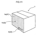
- the method comprises the steps of: irradiating light to an imaging target object S by light emitting means 4 and receiving the reflected light from the object by light receiving means 5 and imaging the object S about the reflected light, wherein the object S includes at least two portions d1, d2 having different reflection factors for a near-infrared range light from each other and the light emitting means 4 irradiates the light which includes the near-infrared range light component and the light receiving means 5 receives the near-infrared range light component.
- the light receiving means 5 comprises a charge-coupled device.
- the light receiving means 5 receives light whose visible light component has been eliminated by a visible light cut filter 10.
- the light emitting means 4 irradiates, to the object, light whose visible light component has been eliminated by a visible light cut filter 10.
- the one d2 of the two portions having different reflection factors for a near-infrared range light from each other is an identifier marking 3 printed on the object S.
- the object S includes a raw material portion and a portion printed with an ink having a different reflection factor for the near-infrared range light from the raw material portion 1a or includes the two portions d1 and d2 printed with at least two kinds of ink having different reflection factors for the near-infrared range light from each other.
- the light receiving means 5 comprises a charge-coupled device.
- the apparatus further comprises a visible light cut filter 10 for eliminating visible light component from the light to be received by the light receiving means 5.
- the apparatus further comprises a visible light cut filter 10 for eliminating visible light component from the light to be irradiated by the light emitting means 4.
- the light emitting means 4 emits light including near-infrared light component to the object including an identifier marking 3 printed thereon as the one d2 of the two portions having different reflection factors for a near-infrared range light from each other.
- the object S includes a raw material portion and a portion printed with an ink having a different reflection factor for the near-infrared range light from the raw material portion 1a or includes the two portions d1 and d2 printed with at least two kinds of ink having different reflection factors for the near-infrared range light from each other.
- the object is adapted for use with an imaging apparatus 6 including light emitting means 4 for irradiating light and light receiving means 5 for receiving the irradiated light; wherein the object includes a raw material portion 1a and a portion 2b printed with an ink having a different reflection factor for the near-infrared range light from the raw material portion 1a or includes two portions d1 and d2 printed with at least two kinds of ink having different reflection factors for the near-infrared range light from each other.
- the method comprises the step of printing a portion 1b of an imaging target object S for printing with an ink having a different reflection factor for a near-infrared range light than a raw material portion 1a of the object S or printing two portions 1a and 1b of the object S with at least two kinds of ink having different reflection factors for the near-infrared range light from each other.
- the target object to be imaged includes at least two portions having different near-infrared range light reflection factors from each other. Then, when this object is irradiated with the near-infrared light, the light receiving means can detect the reflection factor difference between the two portions, so that these two portions can be detected separately from each other owning to the distinct contrast in the infrared light range provided therebetween.
- the two portions are referred to as a first portion and a second portion
- recognition of the identifier marking with a distinct contrast therebetween would be made possible also by varying reflection factors of these portions in the visible light range.
- the recognition becomes difficult if both of the first and second portions have light colors or dark colors or one of them has a dark color.
- the target object to be imaged may be printed just like the conventionally printed object when seen by human eyes, that is, in the visible range.
- the identifier marking (such as the date of manufacture, the date recommended by the manufacturer by which the product is to be consumed, (referred to as “best-consumed-by date” hereinafter) etc.) may be recognized in the near-infrared range light and the recognition of the identifier marking by imaging apparatus or method may be carried out reliably even in the case of at a high-speed transport in the manufacture line.
- the image of either one of these portions may be picked up distinctly from the other, even when these first and second portions are formed as normal visible portions and regardless of the color tone relationship therebetween.
- the two portions are an identifier marking and background
- the following function and effect can be achieved.
- the light receiving means received light components in both the visible range light and the near-infrared range light
- imaging result in the visible range light where the distinction between the identifier marking and the background is difficult and imaging result in the near-infrared range light where the distinction between the identifier marking and the background is easy would be obtained in a mixed state.
- some additional processing means would be needed in the image processing system for selectively obtaining the imaging result in the near-infrared range light alone, by e.g. providing a filter for canceling the imaging result in the visible range light.
- the light receiving means is adapted for receiving only the near-infrared light component of the light whose visible range light component has been eliminated already, the light receiving means receives only the near-infrared light component even when the irradiated light form the light irradiating means contains visible range light component also. Therefore, the image of the marking may be picked up reliably and easily, without having to provide such additional image processing or separating means as described above. Further, in case such additional image processing means were incorporated within the image processing system for eliminating the visible range light component, this could interfere with the image processing circuit of the system for processing the imaging result for the near-infrared light component. On the other hand, such disadvantageous interference does not occur in the case of such mechanical means as the visible light cut filter. As a result, the image recognition precision will be improved and also additional image processing step (or means) for eliminating the imaging result for the visible range light will become unnecessary. Consequently, the entire image processing control scheme may be simplified.
- the two portions are an identifier marking and background
- the following function and effect can be achieved.
- the light emitting means emitted light components in both the visible range and the near-infrared range light
- imaging result in the visible range light where the distinction between the identifier marking and the background is difficult and imaging result in the near-infrared range light where the distinction between the identifier marking and the background is easy would be obtained in a mixed state.
- some additional processing means would be needed in the image processing system for selectively obtaining the imaging result in the near-infrared range light alone, by e.g. providing a filter for canceling the imaging result in the visible range light.
- the light emitting means is adapted for emitting only the near-infrared light component of the light whose visible range light component has been eliminated already
- the light receiving means receives only the near-infrared light component even when the irradiated light form the light irradiating means contains visible range light component. Therefore, the image of the marking may be picked up reliably and easily, without having to provide such additional image processing means as described above.
- additional image processing means were included in the image processing system for eliminating the visible range light component, this could interfere with the image processing circuit of the system for processing the imaging result for the near-infrared range light component.
- such interference does not occur in the case of such mechanical means as the visible light cut filter.
- the image recognition precision will be improved and also additional image processing step (or means) for eliminating the imaging result for the visible range light will become unnecessary. Consequently, the entire image processing control scheme may be simplified.
- an identifier marking such as the best-consumed-by date is printed on a material surface of the target object to be imaged such as on an outer surface of a cardboard box, a bottle, a can or the like of a drink product or in case such identifier marking is printed on various ornamental designs, by forming the material surface and the identifier marking or the design and the marking as the two portions constructed above, the identifier marking can be recognized reliably and precisely.
- this imaging method will be useful for checking or inspection in a manufacture line of products for instance.
- the inks used for the visibly different printed portions may be varied from each other in their reflection factors for the near-infrared range light.
- a target object to be imaged with a marking which cannot be readily recognized by the conventional method e.g. a target object having an identifier marking on an ornamental design printed in a dark color
- clear distinction between these printed portions, i.e. the marking and the design is still possible by selecting in advance the inks used for the printing of these portions with consideration to their reflection factors for the near-infrared range light.
- substantially same function and effect as those by the method according to claim 1 can be obtained.
- substantially same function and effect as those by the method according to claim 2 can be obtained.
- substantially same function and effect as those by the method according to claim 3 can be obtained.
- substantially same function and effect as those by the method according to claim 4 can be obtained.
- substantially same function and effect as those by the method according to claim 5 can be obtained.
- substantially same function and effect as those by the method according to claim 6 can be obtained.
- the inks used for the visibly different printed portions may be varied from each other in their reflection factors for the near-infrared range light.
- the inks used for the visibly different printed portions may be varied from each other in their reflection factors for the near-infrared range light.
- An imaging method and an imaging apparatus relating to the present invention are for use in inspecting whether an identifier marking such as a date of manufacture is printed properly on a side face of a cardboard box in a manufacture line for packing a predetermined number of products such as bottled soft or hard drinks therein one after another into the box.
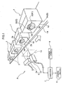
- a conveyer 14 for this inspecting process in the manufacture line for packing, there is provided a conveyer 14 for continuously conveying cardboard boxes (an example of container) 1 each containing a predetermined number of drink products therein in a sealed state.
- each cardboard box 1 On a side face 1A of each cardboard box 1, an ornamental design (an example of a "first portion d1") 2 is printed in advance by an unillustrated printer and also an identifier marking (an example of a "second portion d2") 3 such as the date of manufacture is printed in advance by an unillustrated stamper on the ornamental design 2 after the predetermined number of drink products were packed in the box.
- the conveyer 14 coveys these cardboard boxes 1 each bearing the identifier marking 3 on the side face thereof and having its top face closed. Then, on the lateral side of this conveyer 14, there is installed an inspecting apparatus A for inspecting whether the printed identifier marking 3 of the date of manufacture is printed properly on each both or not.
- the inspecting apparatus A includes an imaging apparatus 6 for irradiating light from a light emitting LED (an example of “light emitting means") 4 to the side face 1A (an example of "target object to be imaged” and “target object to be imaged for printing") of the cardboard box 1 and receiving the light reflected therefrom by a CCD camera (an example of "light receiving means") 5 for imaging the box side face 1A.
- the apparatus further includes a controller 7, a storage means 8 for storing in advance a predetermined correct date of manufacture as a reference, and a display device 9 for displaying matching or non-matching between the date of manufacture of the identifier marking 3 detected by the imaging apparatus 6 and the reference date of manufacture stored in the storage means 8.
- the light emitting LED 4 is adapted for emitting light having a near-infrared light component e.g. in the range of 700 nm to 900 nm as a near-infrared light.
- the CCD camera 5 is adapted for receiving the near-infrared light.
- a visible light cut filter 10 for cutting visible light component so as to allow only the near-infrared light component contained in the reflected light to reach the CCD camera 5, whereby subsequent image processing operation can omit processing of visible light component data contained in the imaging result.
- the ornamental design 2 printed on the box side face 1A includes a circular portion 2b printed with an ink having a dark color, e.g. purple (or dark grey) and a crescent portion 2a printed with a red ink with a part thereof cut away by the presence of the circular portion adjacent thereto.
- the identifier making 3 of the date of manufacture is printed as being superposed thereon.
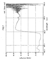
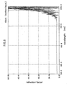
- the purple (or dark grey) ink and the red ink used for the ornamental design 2 are conventional inks which absorb only the visible range light components. For reference, reflection factors of these inks for these wave lengths are illustrated by characteristics graphs in Figs. 5 through 7.
- the identifier marking 3 is printed with an ink containing a dye of carbon black which absorbs both the visible light components and the near-infrared light component. Its characteristics graph is shown in Fig. 8.
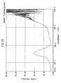
- the conventional ink dye typically employed for printing presents its color by absorbing the other colors in the visible range light than the color of its own. With such dye, as illustrated by the graphs of Figs. 5 through 7, it reflects the light in the infrared light range having a wavelength of 800 nm or greater (e.g. 800 nm to 900 nm), just like the white color (see its graph in Fig. 9). In contrast, some dyes such as carbon black, cyanine green etc., have low reflection factors for the near-infrared light range (the characteristics graph of carbon black is shown in Fig. 8 and the characteristics graph of cyanine green is shown in Fig. 10).
- an ink containing a dye having a low reflection factor for the near-infrared light range is employed as the ink for printing the identifier marking 3.
- an ink containing a dye having a high reflection factor for the near-infrared range light is employed as the ink for printing the ornamental design 2 of the side face 1A.
- an ink containing a dye having a high reflection factor for the near-infrared range light is employed.
- a near-infrared light is employed for illumination of the imaging apparatus 6.
- the identifier marking 3 since the identifier marking 3 has a low reflection factor for the near-infrared range light component, there is produced a significant difference in the reflected light amount relative to the ornamental design 2 (and the background 1a), that is, a great difference in the reflection factor for the near-infrared range light.
- the CCD camera 5 will recognize the identifier marking 3 as a black image and also recognize the other portions as whitish images.
- the identifier marking 3 may be detected easily and reliably.
- the identifier marking 3 portion is also possible to adapt the identifier marking 3 portion to reflect the near-infrared range light component and also to adapt the other portions (that is, the ornamental design 2 and the background 1a) to have lower reflection factors for the near-infrared range light, so that the camera will recognize as the identifier marking 3 as a whitish image.
- substantially same effect that is, the easy and reliable recognition of the identifier marking 3, can be achieved.
- the subsequent image processing operation of comparing it with the reference manufacture date stored in advance in the storage means 8 may be carried out easily and reliably by the controller 7. Then, if there is found non-matching therebetween, the cardboard box bearing this marking is determined as a "defective", so that any appropriate operation subsequent thereto may be carried out. For instance, the defective will automatically be picked up away from the conveyer 14 or the discovery of the defective will be notified by mean of an alarm device.
- the dyes which reflect the near-infrared range light components are commonly available in many colors. Then, by appropriately mixing some of them, it becomes possible to express substantially all colors including the three primary colors (see Fig. 4) in the visible range light. And, the near-infrared light having the wavelength of about 800 nm (e.g. 700 nm to 1000 nm) can be picked up with sufficient sensitivity by a standard CCD camera commonly available on the market.
- a visible light emitting device 11 emitting only the visible light components irradiates the visible light to the side face 1A bearing the ornamental design 2 including the circular portion 2b having a relatively dark purple color and the crescent portion 2a having red color and the identifier marking 3 of e.g. the date of manufacture and the black-and-white CCD camera 12 is employed for receiving the light reflected from the face (this method will be referred to as the "conventional inspection method").
- the visible light is well reflected by the background 1a portion which comprises the raw material cardboard face, but not reflected will by the ornamental design 2 or the identifier marking 3. So that, there is produced substantially no reflected light amount difference (i.e. the contrast difference) between the ornamental design 2 and the identifier marking 3. As a result, accurate recognition of the identifier marking 3 is difficult.
- a purple filter 13 is disposed in front of the visible light source 11 so as to irradiate a purple-colored visible light to the box side face 1A (this method will be referred to as "filter method 1" hereinafter).
- filter method 1 this method will be referred to as "filter method 1" hereinafter.
- the reflected light amount difference may be improved for facilitating the recognition of the identifier marking 3 at this part.
- a purple filter 13 is disposed in front of the CCD camera 12, so that the reflected light from the box side face 1A is changed into a purple light which is then received by the CCD camera 12 (this method will be referred to as "filter method 2" hereinafter).
- filter method 2 the reflected light amount may be increased for the circular portion 2b, so that the recognition of the part of the identifier marking 3 located within this circular portion 2b may be facilitated.
- the other part of the identifier marking 3 located within the crescent portion 2a cannot be recognized easily.
- this method cannot achieve accurate and reliable recognition of the entire identifier marking 3, either.
- this method also suffers other disadvantages of requiring preparation of a filter of a different color each time the color of the design 2 is changed and requiring troublesome operation of replacing the filters.
- the light emitting means 4 may be modified to emit only the near-infrared light component by using e.g. a near-infrared light emitting element.
- this light emitting means 4 may comprise a combination of a light emitter such as an incandescent lamp, a fluorescent lamp, a stroboscopic lamp, or a halogen lamp all of which emit light over a wide wavelength range and a visible light cut filter disposed in front of this light emitter, so that only the near-infrared range components of the light from the emitter will be irradiated.
- the light receiving means 5 may be adapted for receiving only the near-infrared range light component.
- the entire side face 1A of the cardboard box 1 may be printed in green, yellow or the like as the background 1a and on this monochromatic background 1a, the identifier marking 3 of the best-consumed-by date may be printed.
- the background 1a constitutes the first portion d1
- the date or marking 3 constitutes the second portion d2, respectively.
- the target object to be imaged S may include three or more portions having mutually different reflection factors for the near-infrared range light, such as the raw material portion, an ornamental design printed on the material portion and an identifier marking printed on the ornamental design.
- the light from the light emitting means 4 is irradiated to the target object to be imaged S having a first portion d1 as the background and a second portion d2 as the identifier marking and the light receiving means 5 receives the reflected light therefrom to pick up the image of the object S.
- the first portion d1 and the second portion d2 are adapted to have different reflection factors for the near-infrared range light component from each other, so as to obtain a greater contrast between the first portion d1 and the second portion d2, whereby the recognition thereof may be carried out easily, speedily and reliably.
Landscapes
- Physics & Mathematics (AREA)
- Engineering & Computer Science (AREA)
- General Physics & Mathematics (AREA)
- Analytical Chemistry (AREA)
- General Health & Medical Sciences (AREA)
- Health & Medical Sciences (AREA)
- Life Sciences & Earth Sciences (AREA)
- Chemical & Material Sciences (AREA)
- Multimedia (AREA)
- Biochemistry (AREA)
- Theoretical Computer Science (AREA)
- Immunology (AREA)
- Pathology (AREA)
- Investigating Materials By The Use Of Optical Means Adapted For Particular Applications (AREA)
- Image Processing (AREA)
- Image Analysis (AREA)
- Inking, Control Or Cleaning Of Printing Machines (AREA)
Abstract
Description
Claims (14)
- An imaging method comprising the steps of: irradiating light to a target object to be imaged by light emitting means and receiving the reflected light from the object by light receiving means and imaging the object about the reflected light, wherein said object includes at least two portions having different reflection factors for a near-infrared range light from each other and wherein the light emitting means irradiates the light which includes the near-infrared range light component and the light receiving means receives the near-infrared range light component.
- The method according to claim 1, wherein the light receiving means comprises a charge-coupled device.
- The method according to claim 1, wherein the light receiving means receives light whose visible light component has been eliminated by a visible light cut filter.
- The method according to claim 1, wherein the light emitting means irradiates, to the object, light whose visible light component has been eliminated by a visible light cut filter.
- The method according to any one of claims 1-4, wherein the one of the two portions having different reflection factors for a near-infrared range light from each other is an identifier marking printed on the object.
- The method according to any one of claims 1-4, wherein the object includes a raw material portion and a portion printed with an ink having a different reflection factor for the near-infrared range light from the raw material portion or includes the two portions printed with at least two kinds of ink having different reflection factors for the near-infrared range light from each other.
- An imaging apparatus for imaging a target object by irradiating light on the object by light emitting means and receiving the reflected light from the object by light receiving means, wherein the light emitting means irradiates light including the near-infrared range light component on the object including at least two portions having different reflection factors for a near-infrared range light from each other and the light receiving means receives the near-infrared range light component.
- The apparatus according to claim 7, wherein the light receiving means comprises a charge-coupled device.
- The apparatus according to claim 7, further comprising a visible light cut filter for eliminating visible light component from the light to be received by the light receiving means.
- The apparatus according to claim 7, further comprising a visible light cut filter for eliminating visible light component from the light to be irradiated by the light emitting means.
- The apparatus according to any one of claims 7-10, wherein the light emitting means emits light including near-infrared light component to the object including an identifier marking printed thereon as the one of the two portions having different reflection factors for a near-infrared range light from each other.
- The apparatus according to any one of claims 7-10, wherein the object includes a raw material portion and a portion printed with an ink having a different reflection factor for the near-infrared range light from the raw material portion or includes the two portions printed with at least two kinds of ink having different reflection factors for the near-infrared range light from each other.
- A target object to be imaged for use with an imaging apparatus including light emitting means for irradiating light and light receiving means for receiving the irradiated light; wherein the object includes a raw material portion and a portion printed with an ink having a different reflection factor for the near-infrared range light from the raw material portion or includes two portions printed with at least two kinds of ink having different reflection factors for the near-infrared range light from each other.
- A printing method comprising the step of printing a portion of an image pickup target object for printing with an ink having a different reflection factor for a near-infrared range light than a raw material portion of the object or printing two portions of the object with at least two kinds of ink having different reflection factors for the near-infrared range light from each other.
Applications Claiming Priority (3)
| Application Number | Priority Date | Filing Date | Title |
|---|---|---|---|
| JP2000333118A JP2002137369A (en) | 2000-10-31 | 2000-10-31 | Imaging method, imaging apparatus, imaging target, and printing method |
| JP2000333118 | 2000-10-31 | ||
| PCT/JP2001/009457 WO2002037417A1 (en) | 2000-10-31 | 2001-10-26 | Imaging method and imaging device, object to be imaged, printing method |
Publications (2)
| Publication Number | Publication Date |
|---|---|
| EP1331603A1 true EP1331603A1 (en) | 2003-07-30 |
| EP1331603A4 EP1331603A4 (en) | 2007-02-07 |
Family
ID=18809242
Family Applications (1)
| Application Number | Title | Priority Date | Filing Date |
|---|---|---|---|
| EP01976855A Withdrawn EP1331603A4 (en) | 2000-10-31 | 2001-10-26 | IMAGING METHOD AND IMAGING DEVICE, OBJECT TO BE VIEWED, AND PRINTING METHOD |
Country Status (7)
| Country | Link |
|---|---|
| US (1) | US20020191174A1 (en) |
| EP (1) | EP1331603A4 (en) |
| JP (1) | JP2002137369A (en) |
| CN (1) | CN1278272C (en) |
| MY (1) | MY128390A (en) |
| TW (1) | TW539909B (en) |
| WO (1) | WO2002037417A1 (en) |
Families Citing this family (5)
| Publication number | Priority date | Publication date | Assignee | Title |
|---|---|---|---|---|
| EP1463306B8 (en) * | 2003-03-25 | 2009-11-11 | Panasonic Corporation | Imaging device that prevents loss of shadow detail |
| US7490773B2 (en) * | 2004-12-03 | 2009-02-17 | Mcvicker Henry J | Apparatus and method for obtaining an image of an arcuate surface |
| JP4578447B2 (en) * | 2006-08-02 | 2010-11-10 | 学校法人帝京大学 | Multiple vehicle monitoring method and monitoring system in dark place |
| USD711883S1 (en) * | 2013-03-15 | 2014-08-26 | Meditory Llc | Scanner |
| JP7037173B2 (en) * | 2018-02-14 | 2022-03-16 | ダックエンジニアリング株式会社 | Quality inspection equipment for corrugated cardboard sheets |
Family Cites Families (22)
| Publication number | Priority date | Publication date | Assignee | Title |
|---|---|---|---|---|
| US3933094A (en) * | 1973-11-19 | 1976-01-20 | United States Envelope Company | Substrate having colored indicia thereon for read-out by infrared scanning apparatus |
| JPS58134782A (en) * | 1982-02-05 | 1983-08-11 | Kyodo Printing Co Ltd | Reference print |
| JPH01292485A (en) * | 1988-05-19 | 1989-11-24 | Pioneer Electron Corp | Multiply printed bar code system |
| US4889367A (en) * | 1988-10-07 | 1989-12-26 | Frito-Lay, Inc. | Multi-readable information system |
| JPH02265355A (en) * | 1989-04-05 | 1990-10-30 | Pioneer Electron Corp | Print code pattern forming method |
| US5348348A (en) * | 1989-09-26 | 1994-09-20 | Toyo Ink Manufacturing Co., Ltd. | Data-written medium |
| JPH03154187A (en) * | 1989-11-10 | 1991-07-02 | Toyo Ink Mfg Co Ltd | Record identifiable by near infrared rays |
| US5522623A (en) * | 1990-03-29 | 1996-06-04 | Technical Systems Corp. | Coded identification card and other standardized documents |
| JPH0567252A (en) * | 1991-07-22 | 1993-03-19 | Nec Corp | Business card with barcode and its barcode reader |
| US5354977A (en) * | 1992-02-27 | 1994-10-11 | Alex Roustaei | Optical scanning head |
| JPH06164914A (en) * | 1992-11-20 | 1994-06-10 | Toppan Printing Co Ltd | Copy protection method and copier |
| JP3238507B2 (en) * | 1992-12-21 | 2001-12-17 | 旭光学工業株式会社 | Special symbol reader |
| JPH06210987A (en) * | 1993-01-19 | 1994-08-02 | Canon Inc | Recording medium of information made invisible, detecting device of information made invisible and recording agent |
| US5881886A (en) * | 1994-03-18 | 1999-03-16 | Brown University Research Foundation | Optically-based methods and apparatus for sorting garments and other textiles |
| US5903340A (en) * | 1994-03-18 | 1999-05-11 | Brown University Research Foundation | Optically-based methods and apparatus for performing document authentication |
| US6100973A (en) * | 1994-03-18 | 2000-08-08 | Spectra Science Corporation | Methods and apparatus for performing microanalytical techniques using photolithographically fabricated substrates having narrow band optical emission capability |
| US5851225A (en) * | 1994-03-18 | 1998-12-22 | Spectra Science Corporation | Photoemitting catheters and other structures suitable for use in photo-dynamic therapy and other applications |
| US5448582A (en) * | 1994-03-18 | 1995-09-05 | Brown University Research Foundation | Optical sources having a strongly scattering gain medium providing laser-like action |
| JPH0855181A (en) * | 1994-08-10 | 1996-02-27 | Kansai Paint Co Ltd | How to read invisible markings |
| JPH08136346A (en) * | 1994-11-07 | 1996-05-31 | Toppan Printing Co Ltd | Ink amount measuring device |
| JP3068483B2 (en) * | 1996-02-08 | 2000-07-24 | 株式会社東芝 | Pattern reading method and optical signal reading device |
| US5912452A (en) * | 1997-02-06 | 1999-06-15 | Intermec Corporation | Method and apparatus for reading one-and two-dimensional symbols with a linear detector |
-
2000
- 2000-10-31 JP JP2000333118A patent/JP2002137369A/en active Pending
-
2001
- 2001-10-26 CN CNB018033296A patent/CN1278272C/en not_active Expired - Fee Related
- 2001-10-26 US US10/168,406 patent/US20020191174A1/en not_active Abandoned
- 2001-10-26 EP EP01976855A patent/EP1331603A4/en not_active Withdrawn
- 2001-10-26 WO PCT/JP2001/009457 patent/WO2002037417A1/en not_active Ceased
- 2001-10-30 TW TW090126928A patent/TW539909B/en not_active IP Right Cessation
- 2001-10-30 MY MYPI20015015A patent/MY128390A/en unknown
Also Published As
| Publication number | Publication date |
|---|---|
| JP2002137369A (en) | 2002-05-14 |
| EP1331603A4 (en) | 2007-02-07 |
| CN1278272C (en) | 2006-10-04 |
| MY128390A (en) | 2007-01-31 |
| TW539909B (en) | 2003-07-01 |
| CN1394318A (en) | 2003-01-29 |
| US20020191174A1 (en) | 2002-12-19 |
| WO2002037417A1 (en) | 2002-05-10 |
Similar Documents
| Publication | Publication Date | Title |
|---|---|---|
| US6753527B1 (en) | Method and device for imaging liquid-filling container | |
| EP1176417A1 (en) | Method and device for imaging liquid-filled container | |
| US12209969B2 (en) | Method and device for optically inspecting containers | |
| JP7801713B2 (en) | Imaging device, inspection device, and imaging method | |
| US11195042B2 (en) | Drug inspection assistance device, drug identification device, image processing device, image processing method, and program | |
| JP7740692B2 (en) | Container image acquisition device and image acquisition method, and container inspection device and inspection method using the same | |
| MXPA06008254A (en) | Device and method for detecting contamination in a container. | |
| EP0990891B1 (en) | Method for inspection of rubber product | |
| JP3929647B2 (en) | Tablet appearance inspection device and PTP packaging machine | |
| JP2020106504A (en) | Label inspection device and label inspection method | |
| US20020191174A1 (en) | Imaging method and imaging device, object to be imaged, prining method | |
| JP7217035B2 (en) | CONTAINER INSPECTION DEVICE AND CONTAINER INSPECTION METHOD | |
| JP3668449B2 (en) | Foreign matter detection device in filling liquid such as transparent containers | |
| WO2000065327A1 (en) | Apparatus and method for inspecting multi-layer plastic containers | |
| EP0247742B1 (en) | Image reproduction | |
| JP4736788B2 (en) | Container with optical information, method for reading optical information | |
| JP6878093B2 (en) | Attachment detection device and detection method | |
| JP4984540B2 (en) | Print mark inspection device | |
| JP7340213B1 (en) | Visual inspection device, visual inspection system, and visual inspection method for transparent containers | |
| JPH05332811A (en) | Liquid level measuring method and liquid level measuring device | |
| JP2000255147A (en) | Inspection method and apparatus for printing quality | |
| JP2005227302A (en) | Appearance inspection device and PTP packaging machine equipped with appearance inspection device | |
| JP2010266268A (en) | Detection method of abnormalities in prints |
Legal Events
| Date | Code | Title | Description |
|---|---|---|---|
| PUAI | Public reference made under article 153(3) epc to a published international application that has entered the european phase |
Free format text: ORIGINAL CODE: 0009012 |
|
| 17P | Request for examination filed |
Effective date: 20030502 |
|
| AK | Designated contracting states |
Designated state(s): AT BE CH CY DE DK ES FI FR GB GR IE IT LI LU MC NL PT SE TR |
|
| AX | Request for extension of the european patent |
Extension state: AL LT LV MK RO SI |
|
| A4 | Supplementary search report drawn up and despatched |
Effective date: 20070105 |
|
| RIC1 | Information provided on ipc code assigned before grant |
Ipc: G06T 7/00 20060101ALI20061229BHEP Ipc: G01N 21/956 20060101ALI20061229BHEP Ipc: G01B 11/24 20060101ALI20061229BHEP Ipc: B41F 33/14 20060101ALI20061229BHEP Ipc: G06T 1/00 20060101AFI20020513BHEP |
|
| 17Q | First examination report despatched |
Effective date: 20070426 |
|
| RAP1 | Party data changed (applicant data changed or rights of an application transferred) |
Owner name: SUNTORY HOLDINGS LIMITED |
|
| GRAP | Despatch of communication of intention to grant a patent |
Free format text: ORIGINAL CODE: EPIDOSNIGR1 |
|
| RTI1 | Title (correction) |
Free format text: PRINTING METHOD AND PRINTED OBJECT |
|
| STAA | Information on the status of an ep patent application or granted ep patent |
Free format text: STATUS: THE APPLICATION IS DEEMED TO BE WITHDRAWN |
|
| 18D | Application deemed to be withdrawn |
Effective date: 20120103 |