EP1331173A1 - Paper container - Google Patents
Paper container Download PDFInfo
- Publication number
- EP1331173A1 EP1331173A1 EP01972611A EP01972611A EP1331173A1 EP 1331173 A1 EP1331173 A1 EP 1331173A1 EP 01972611 A EP01972611 A EP 01972611A EP 01972611 A EP01972611 A EP 01972611A EP 1331173 A1 EP1331173 A1 EP 1331173A1
- Authority
- EP
- European Patent Office
- Prior art keywords
- synthetic resin
- hole
- layer
- paper
- container
- Prior art date
- Legal status (The legal status is an assumption and is not a legal conclusion. Google has not performed a legal analysis and makes no representation as to the accuracy of the status listed.)
- Granted
Links
Images



Classifications
-
- B—PERFORMING OPERATIONS; TRANSPORTING
- B65—CONVEYING; PACKING; STORING; HANDLING THIN OR FILAMENTARY MATERIAL
- B65D—CONTAINERS FOR STORAGE OR TRANSPORT OF ARTICLES OR MATERIALS, e.g. BAGS, BARRELS, BOTTLES, BOXES, CANS, CARTONS, CRATES, DRUMS, JARS, TANKS, HOPPERS, FORWARDING CONTAINERS; ACCESSORIES, CLOSURES, OR FITTINGS THEREFOR; PACKAGING ELEMENTS; PACKAGES
- B65D5/00—Rigid or semi-rigid containers of polygonal cross-section, e.g. boxes, cartons or trays, formed by folding or erecting one or more blanks made of paper
- B65D5/42—Details of containers or of foldable or erectable container blanks
- B65D5/72—Contents-dispensing means
-
- B—PERFORMING OPERATIONS; TRANSPORTING
- B65—CONVEYING; PACKING; STORING; HANDLING THIN OR FILAMENTARY MATERIAL
- B65D—CONTAINERS FOR STORAGE OR TRANSPORT OF ARTICLES OR MATERIALS, e.g. BAGS, BARRELS, BOTTLES, BOXES, CANS, CARTONS, CRATES, DRUMS, JARS, TANKS, HOPPERS, FORWARDING CONTAINERS; ACCESSORIES, CLOSURES, OR FITTINGS THEREFOR; PACKAGING ELEMENTS; PACKAGES
- B65D5/00—Rigid or semi-rigid containers of polygonal cross-section, e.g. boxes, cartons or trays, formed by folding or erecting one or more blanks made of paper
- B65D5/42—Details of containers or of foldable or erectable container blanks
- B65D5/72—Contents-dispensing means
- B65D5/74—Spouts
-
- B—PERFORMING OPERATIONS; TRANSPORTING
- B65—CONVEYING; PACKING; STORING; HANDLING THIN OR FILAMENTARY MATERIAL
- B65D—CONTAINERS FOR STORAGE OR TRANSPORT OF ARTICLES OR MATERIALS, e.g. BAGS, BARRELS, BOTTLES, BOXES, CANS, CARTONS, CRATES, DRUMS, JARS, TANKS, HOPPERS, FORWARDING CONTAINERS; ACCESSORIES, CLOSURES, OR FITTINGS THEREFOR; PACKAGING ELEMENTS; PACKAGES
- B65D2231/00—Means for facilitating the complete expelling of the contents
- B65D2231/02—Precut holes or weakened zones
-
- Y—GENERAL TAGGING OF NEW TECHNOLOGICAL DEVELOPMENTS; GENERAL TAGGING OF CROSS-SECTIONAL TECHNOLOGIES SPANNING OVER SEVERAL SECTIONS OF THE IPC; TECHNICAL SUBJECTS COVERED BY FORMER USPC CROSS-REFERENCE ART COLLECTIONS [XRACs] AND DIGESTS
- Y02—TECHNOLOGIES OR APPLICATIONS FOR MITIGATION OR ADAPTATION AGAINST CLIMATE CHANGE
- Y02W—CLIMATE CHANGE MITIGATION TECHNOLOGIES RELATED TO WASTEWATER TREATMENT OR WASTE MANAGEMENT
- Y02W90/00—Enabling technologies or technologies with a potential or indirect contribution to greenhouse gas [GHG] emissions mitigation
- Y02W90/10—Bio-packaging, e.g. packing containers made from renewable resources or bio-plastics
-
- Y—GENERAL TAGGING OF NEW TECHNOLOGICAL DEVELOPMENTS; GENERAL TAGGING OF CROSS-SECTIONAL TECHNOLOGIES SPANNING OVER SEVERAL SECTIONS OF THE IPC; TECHNICAL SUBJECTS COVERED BY FORMER USPC CROSS-REFERENCE ART COLLECTIONS [XRACs] AND DIGESTS
- Y10—TECHNICAL SUBJECTS COVERED BY FORMER USPC
- Y10T—TECHNICAL SUBJECTS COVERED BY FORMER US CLASSIFICATION
- Y10T428/00—Stock material or miscellaneous articles
- Y10T428/13—Hollow or container type article [e.g., tube, vase, etc.]
- Y10T428/1303—Paper containing [e.g., paperboard, cardboard, fiberboard, etc.]
Definitions
- the present invention relates to a paper container for liquid foods, which is of a laminate structure made of a container material from which aluminum foil is omitted and which includes a thin paper used in a layered material that covers a liquid take-out port from inside to make a construction closer to that of a natural material.
- a base material 1 made of paper and provided with a through-hole 2 serving as a liquid take-out port is laminated with synthetic resin layers 3 and 4 made of a synthetic resin such as low density polyethylene on at least the outermost surface and innermost surface (the surface where the liquid contacts the content) thereof as shown in Figs. 9 and 10.
- Fig. 9 shows a paper container with a straw hole, with the above-mentioned through-hole 2 serving as a straw hole 14. This is designed to pierce a straw through the synthetic resin layers 3 and 4 that block the through hole 2 in the base material 1 to open the through-hole 2.
- Fig. 10 shows a paper container of the pull-tab type in which a pull-tab 15 is bonded to the portion where the through-hole 2 provided in the above-mentioned base material 1 is blocked with the synthetic resin layer 3 constituting an outermost surface of the laminate. This is designed such that pulling up the pull-tab 15 will cut off the portions of the synthetic resins 3 and 4 that block the through-hole 2 provided in the above-mentioned base material 1, thereby opening the through-hole 2.
- Fig. 11 shows a paper container with an opening device that includes a container material 16 of a laminate construction having a base material 1 made of paper with at least the outermost and innermost surfaces thereof being constituted by synthetic resin layers 3 and 4.
- the container material 16 is provided with a through-hole 2 serving as a liquid take-out port and a lower plate 18 made of a synthetic resin having a through-hole 17 of a size equivalent to or smaller than the through-hole 2 is bonded to the surface of the container material 16 such that the through-hole 17 of the lower plate 18 is positioned in the through-hole 2 formed in the above-mentioned container material 16.
- an engaging projection 20 that an upper plate 19 has is fitted from the surface side of the container material 16 and from the rear side of the above-mentioned container material 16 is bonded a synthetic resin film 21 to the periphery of the above-mentioned through-hole 2 and the top surface of the engaging projection 20 of the above-mentioned upper plate 19 to provide an opening device 27.
- This paper container is designed such that pulling up the upper plate 19 from the lower plate 18 will cut off the portion of the synthetic resin film 21 that is bonded to the periphery of the above-mentioned through-hole 2 of the above-mentioned container material 16 and the top surface of the engaging projection 20 of the above-mentioned upper plate 19 and that blocks the through-hole 2, thereby opening the through-hole 2.
- an aluminum foil layer 5 is laminated as a barrier layer in the above-mentioned paper container.
- the aluminum foil layer 5 is laminated between the base material 1 and the synthetic resin layer 4. Between the base material 1 and the aluminum foil layer 5 is provided an adhesive layer 6 made of a synthetic resin. Also in the paper container shown in Fig. 11, the aluminum foil layer 5 is laminated between the base material 1 and the synthetic resin layer 4. Between the base material 1 and the aluminum foil layer 5 is provided an adhesive layer 6 made of a synthetic resin.
- the synthetic resin film 21 is of a three-layer structure in which the aluminum foil layer 5 is laminated between two synthetic resin layers 22 and 23, with the periphery of the above-mentioned through-hole 2 of the container material 16 and the top surface of the engaging projection 20 of the above-mentioned upper plate 19 being bonded to the synthetic resin layer 22.
- paper containers for long-term storage with a synthetic resin layer made of an ethylene/vinyl alcohol copolymer, an aliphatic polyamide, or the like as a barrier layer in place of the aluminum foil layer 5 have come into sight.
- the through-hole 2 is blocked with at least three resin layers: two layers composed of a synthetic resin layer serving as a barrier layer and a synthetic resin layer serving as a liquid contact surface, and one layer constituting the outermost layer.
- a synthetic resin layer serving as a barrier layer and a synthetic resin layer serving as a liquid contact surface are laminated inside the base material 1, and further, a synthetic resin layer serving as a barrier layer is laminated on the synthetic resin film 21.
- the inventors of the present invention have made extensive studies on the breakage of the synthetic resin layers 3 and 4 and synthetic resin film 21 that block the through-hole 2 serving as a liquid take-out port. As a result, they have confirmed that in the conventional paper containers in which the aluminum foil layer 5 is used as a barrier layer, the rigidity of the aluminum foil layer 5 influences the rupturability of the synthetic resin layers 3 and 4 and synthetic resin film 21 and have focused attention to lamination and integration of a rigid material in place of the aluminum foil layer to the synthetic resin layers 3 and 4 and synthetic resin film 21, thereby achieving the present invention.
- An object of the present invention is to provide a paper container that allows opening of a liquid take-out port to be performed easily and neatly.
- the object of the present invention is achieved by providing a paper container that includes a laminate structure having a base material made of paper, at least outermost and innermost surfaces of the laminate structure being constituted by synthetic resin layers, respectively, the above-mentioned base material being provided with a through-hole serving as a liquid take-out port, in which the paper container is of a laminate construction in which the above-mentioned through-hole is covered from inside by a layered material of at least two layers consisting of a synthetic resin layer and a thin paper layer integrated to each other.
- the above-mentioned layered material that covers the above-mentioned through-hole from inside includes at least one thin paper layer composed of wood fiber and/or non-wood fiber having a basis weight of 5 to 65 g/m 2 .
- the respective interlayer strengths between the thin paper layer and each of the adjacent synthetic resin layers in the above-mentioned layered material that covers the above-mentioned through-hole from inside are at least 30 g/15 mm or more.
- the interlayer strength indicates a force required for peeling each layer when each layer of a rectangular test piece with a width of 15 mm was drawn in the direction at an angle of 180 degrees by using a tensile test machine.
- At least one of the above-mentioned synthetic resin layers of the above-mentioned layered material that cover the above-mentioned through-hole from inside has at least barrier property or light-shielding property.
- At least one of the above-mentioned thin paper layer of the above-mentioned layered material that covers the above-mentioned through-hole from inside is imparted with at least barrier property or light-shielding property by printing or the like.
- a paper container that includes a container material of a laminate structure having a base material made of paper, at least outermost and innermost surfaces of the laminate structure being constituted by synthetic resin layers, the container material being provided with a first through-hole serving as a liquid take-out port, a lower plate made of a synthetic resin provided with a second through-hole of a size equivalent to or smaller than the first through-hole being bonded to the surface of the container material with the second through-hole of the lower plate being positioned in the first through-hole formed in the above-mentioned container material, and an upper plate having an engaging projection which is fitted in the second through-hole of the above-mentioned lower plate from a surface side of the container material, and a synthetic resin film bonded to a periphery of the above-mentioned first through-hole and the top surface of the engaging projection of the above-mentioned upper plate from a rear side of the above-mentioned container material to define an opening device, in
- At least one thin paper laminated to the above-mentioned layered material includes wood fiber and/or non-wood fiber having a basis weight of 5 to 65 g/m 2 .
- the respective interlayer strengths between the above-mentioned thin paper and each of the adjacent laminate are at least 30 g/15 mm or more.
- At least one layer of the above-mentioned layered material has at least barrier property or light-shielding property.
- At least one of the above-mentioned thin papers is imparted with at least barrier property or light-shielding property by printing or the like.
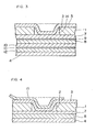
- Figs. 1 to 3 illustrate Examples 1 to 3 embodying paper containers provided with a straw hole, respectively, and Fig. 4 illustrates Example 5 embodying a paper container of the pull-tab type.
- the paper containers provided with a straw hole and the paper container of the pull-tab type shown in the respective examples include a laminated structure, in which at least the outermost and innermost surfaces of the laminate construction having a base material 1 made of paper are constituted by synthetic resin layers 3 and 4.
- the above-mentioned base material 1 is provided with a through-hole 2 serving as a liquid take-out port.
- At least the above-mentioned through-hole 2 is covered from inside by a layered material of at least two layers made of an integration of the synthetic resin layer 4 or 10 and a thin paper layer 8.
- the above-mentioned base material 1 is the same as the base material in conventional paper containers of this type and is not particularly limited but preferably it has a basis weight of 150 to 400 g/m 2 .
- resin for the synthetic resin layer 3 on the outermost surface examples include low-density polyethylene (LDPE), medium-density polyethylene (MDPE), high-density polyethylene (HDPE), linear low-density polyethylene (LLDPE), polyesters, copolyesters, etc.
- LDPE low-density polyethylene
- MDPE medium-density polyethylene
- HDPE high-density polyethylene
- LLDPE linear low-density polyethylene
- the thin paper layer 8 is preferably made of wood fiber and/or non-wood fiber having a basis weight of 5 to 65 g/m 2 . If the basis weight is less than 5 g/m 2 , the resistance at the time of piercing a straw through or cutting off of the thin paper layer is low but the rigidity is decreased, so that the straw piercing property or property of cutting off the thin paper layer becomes poor. On the other hand, the basis weight of 65 g/m 2 or more results in a high rigidity but an increased resistance at the time of piercing a straw through or cutting off the thin paper.
- the density of the thin paper in the thin paper layer 8 is preferably 0.50 to 1.20 g/m 3 taking into consideration the resistance at the time of piercing a straw or of cutting off.
- the thin paper layer 8 does not necessarily have to be laminated on the entire surface of the base material 1 but it may be laminated in the region where the through-hole 2 is blocked.
- the synthetic resin layer to be integrated with the above-mentioned thin paper layer 8 is not particularly limited.
- the synthetic resin layer 4 on the innermost surface, the synthetic resin layer 10 having gas-barrier property, a light-shielding colored resin layer containing, for example, carbon black, a masking synthetic resin layer containing titanium oxide, etc. may be exemplified.
- low-density polyethylene As the resin in the synthetic resin layer 4 on the innermost surface, low-density polyethylene, medium-density polyethylene, high-density polyethylene, linear low-density polyethylene, polyesters, copolyesters, and low-density polyethylenes synthesized with metallocene catalysts are preferred.
- resin for the synthetic resin layer 10 having barrier property nylons, polyesters, copolyesters, ethylene/vinyl alcohol (EVOH), polyvinyl alcohol (PVOH), silica-deposited films, etc. are preferred.
- the above-mentioned thin paper layer 8 may be imparted with barrier property, light-shielding property, masking property, etc. by printing or the like. In this case, it is preferred that the thin paper layer 8 be laminated on the entire surface of the base material.
- a synthetic resin layer serving as an adhesive is laminated between the thin paper layer 8 and the base material 1.
- the resin for the synthetic resin layer serving as an adhesive low-density polyethylene, medium-density polyethylene, high-density polyethylene, linear low-density polyethylene, polyesters, copolyesters, modified low-density polyethylenes, etc. are preferred.
- the above-mentioned base material 1 and the synthetic resin layer 4 on the innermost surface there may be laminated plural synthetic resin layers or thin paper layers in addition to the above-mentioned layers. At least one of such synthetic resin layers or thin paper layers may be imparted with the barrier property, light-shielding property, masking property, etc. as described above.
- the respective interlayer strengths between the synthetic resin layer 4 or 10 and the thin paper layer 8 and between the synthetic resin layer 7 and the thin paper layer 8 are preferably at least 30 g/15 mm or more.
- the respective interlayer strengths between the synthetic resin layer 4 or 10 and the thin paper layer 8 and between the synthetic resin layer 7 and the thin paper layer 8 in the layered material that covers the through-hole from inside is at least 30 g/15 mm or more in this way as described above, the interlayer strengths between the synthetic resin layer 4 or 10 and the thin paper layer 8 and between the synthetic resin layer 7 and the thin paper layer 8 become strong, so that it is ensured that the rigidity of the thin paper layer 8 can be imparted to the synthetic resin layer 7 and the synthetic resin layer 4 or 10, thereby enabling suppression of the elongating property of the synthetic resin layer 7 and the synthetic resin layer 4 or 10 with reliability, resulting in improved straw piercing property through the straw hole portion or improved property of cutting off the straw hole portion.
- Fig. 1 is a cross-sectional view showing a laminate structure of a paper container with a straw hole according to Example 1 of the present invention.
- This paper container has a laminate structure, in which the thermoplastic synthetic resin layer 3 made of a low-density polyethylene layer and having a thickness of 15 ⁇ m, the base material 1 having a basis weight of 200 g/m 2 provided with the through-hole 2 serving as the straw hole 14, the thermoplastic synthetic resin layer 7 made of a low-density polyethylene and having a thickness of 15 ⁇ m, the thin paper layer 8 having a basis weight of 30 g/m 2 and a thickness of 40 ⁇ m, and the thermoplastic synthetic resin layer 4 made of a low-density polyethylene and having a thickness of 15 ⁇ m are laminated from the outside toward the inside (the side where the content contacts the liquid).
- the layered material having the above-mentioned laminate structure was produced as follows. First, the thin paper layer 8 was bonded and laminated onto the inside of the base material 1 through the thermoplastic synthetic resin layer 7 made of a low-density polyethylene and having a thickness of 15 ⁇ m by sandwich lamination. Subsequently, the thermoplastic synthetic resin layers 3 and 4 made of a low-density polyethylene layer and having a thickness of 15 ⁇ m, were extrusion laminated on both the outermost and innermost surfaces of the resultant, respectively.
- the low-density polyethylene as the thermoplastic synthetic resin layers 3, 4, and 7 was MIRASON 16P manufactured by Mitsui Chemical, Inc.
- the base material 1 was a paperboard having a basis weight of 200 g/m 2 , made from virgin pulps of a conifer and a broad-leaf tree, and the thin paper layer 8 having a basis weight of 30 g/m 2 , made from virgin pulps of a conifer and a broad-leaf tree.
- the respective interlayer bonding strengths between the thin paper layer 8 and the thermoplastic synthetic resin layer 7 or 4 on both sides thereof made of a low-density polyethylene on this occasion were 80 g/15 mm.
- Fig. 2 is a cross-sectional view showing a laminate structure of a paper container with a straw hole according to Example 2 of the present invention.
- This paper container has a laminate structure, in which the thermoplastic synthetic resin layer 3 made of a low-density polyethylene and having a thickness of 15 ⁇ m, the base material 1 having a basis weight of 200 g/m 2 provided with the through-hole 2 serving as the straw hole 14, the thermoplastic synthetic resin layer 7 made of a low-density polyethylene and having a thickness of 15 ⁇ m, a black printing layer 9, the thin paper layer 8 having a basis weight of 40 g/m 2 and a thickness of 50 ⁇ m, the barrier resin layer 10 made of ethylene/vinyl alcohol and having a thickness of 10 ⁇ m and the thermoplastic synthetic resin layer 4 made of a low-density polyethylene and having a thickness of 20 ⁇ m are laminated from the outside toward the inside (the side where the content contacts the liquid).
- the layered material having the above-mentioned laminate structure was produced as follows. First, the thin paper layer 8 provided with the black printing layer 9 was bonded and laminated onto the inside of the base material 1 with the black printing layer 9 directed toward the base material 1 through the thermoplastic synthetic resin layer 7 made of a low-density polyethylene and having a thickness of 15 ⁇ m by sandwich lamination.
- thermoplastic synthetic resin layer 3 made of a low-density polyethylene and having a thickness of 15 ⁇ m
- the barrier resin layer10 made of ethylene/vinyl alcohol and having a thickness of 10 ⁇ m
- the thermoplastic synthetic resin layer 4 made of a low density polyethylene and having a thickness of 20 ⁇ m were co-extrusion laminated on the innermost surface of the resultant such that the barrier resin layer 10 contacts with the thin paper layer 8.
- the low-density polyethylene used as the thermoplastic synthetic resin layers 3 and 7 was MIRASON 16P manufactured by Mitsui Chemical, Inc.
- the base material 1 was a paperboard having a basis weight of 200 g/m 2 , made from virgin pulps of a conifer and a broad-leaf tree, and the thin paper layer 8 having a basis weight of 40 g/m 2 , made from virgin pulps of a conifer and a broad-leaf tree.
- the ethylene/vinyl alcohol as the barrier resin layer 10 was EP-E105 manufactured by Kuraray Co., Ltd.
- thermoplastic synthetic resin layer 4 was J-Rex 154 manufactured by Japan Polyolefins Co., Ltd.
- the respective interlayer strengths between the thin paper layer 8 and the thermoplastic synthetic resin layer 7 made of a low-density polyethylene or the barrier resin layer 10 made of ethylene/vinyl alcohol on this occasion were 70 g/15 mm.
- Fig. 3 is a cross-sectional view showing a laminate structure of a paper container with a straw hole according to Example 3 of the present invention.
- This paper container has a laminate structure, in which the thermoplastic synthetic resin layer 3 made of a low-density polyethylene having a thickness of 15 ⁇ m, the base material 1 having a basis weight of 200 g/m 2 provided with the through-hole 2 serving as the straw hole 14, the thermoplastic synthetic resin layer 7 made of a low-density polyethylene having a thickness of 15 ⁇ m, the black printing layer 9, the thin paper layer 8 having a basis weight of 20 g/m 2 and a thickness of 30 ⁇ m, the barrier resin layer 10 made of ethylene/vinyl alcohol having a thickness of 10 ⁇ m, a white printing layer 11, a thin paper layer 12 having a basis weight of 20g/m 2 and a thickness of 30 ⁇ m, and the thermoplastic synthetic resin layer 4 made of a low-density polyethylene having a thickness of 20 ⁇ m are laminated from the outside toward the inside (the side where the content contacts the liquid).
- the layered material having the above-mentioned laminate structure was produced as follows. First, the thin paper layer 8 provided with the black printing layer 9 was bonded and laminated onto the inside of the base material 1 with the black printing layer 9 directed toward the base material 1 through the thermoplastic synthetic resin layer 7 made of a low-density polyethylene and having a thickness of 15 ⁇ m by sandwich lamination. Further, the thin paper layer 12 provided with the white printing layer 11 was bonded and laminated onto the inside of the resultant, with the white printing layer 11 directed toward the base material 1 through the barrier resin layer 10 made of ethylene/vinyl alcohol and having a thickness of 10 ⁇ m by sandwich lamination.
- thermoplastic resin layer 3 made of a low-density polyethylene having a thickness of 15 ⁇ m was extrusion laminated on the outermost surface of the resultant and the thermoplastic resin layer 4 made of a low-density polyethylene having a thickness of 20 ⁇ m was extrusion laminated on the innermost surface of the resultant.
- the low-density polyethylene as the thermoplastic synthetic resin layers 3 and 7 was MIRASON 16P manufactured by Mitsui Chemical, Inc.
- the base material 1 was a paperboard having a basis weight of 200 g/m 2 , made from virgin pulps of a conifer and a broad-leaf tree, and the thin paper layer 8 and 12 having a basis weight of 20 g/m 2 , made from virgin pulps of a conifer and a broad-leaf tree.
- the ethylene/vinyl alcohol as the barrier resin layer 10 was EP-E105 manufactured by Kuraray Co., Ltd.
- thermoplastic synthetic resin layer 4 was J-Rex 154 manufactured by Japan Polyolefins Co., Ltd.
- the respective interlayer strengths between the thin paper layer 8 and the thermoplastic synthetic resin layer 7 made of a low-density polyethylene or the barrier resin layer 10 made of ethylene/vinyl alcohol, and the respective interlayer strengths among the thin paper layer 12 and the barrier resin layer 10 made of ethylene/vinyl alcohol and thermoplastic resin layer 4 made of a low density polyethylene, on this occasion were 50 to 70 g/15 mm.
- the paper container of this example though not shown had the same laminate structure as that in Example 1 except the basis weight of the thin paper layer 8.
- the thin paper layer 8 in this example had a basis weight of 65 g/m 2 and a thickness of 80 ⁇ m.
- Fig. 4 is a cross-sectional view showing a laminate structure of a paper container of the pull-tab type according to Example 5 of the present invention.
- thermoplastic synthetic resin layer 3 made of the low-density polyethylene layer and having a thickness of 15 ⁇ m
- the base material 1 having a basis weight of 200 g/m 2 provided with the through-hole 2
- the thermoplastic synthetic resin layer 7 made of the low-density polyethylene and having a thickness of 15 ⁇ m
- the thin paper layer 8 having a basis weight of 30 g/m 2 and a thickness of 40 ⁇ m
- the thermoplastic synthetic resin layer 4 made of a low-density polyethylene having a thickness of 15 ⁇ m are laminated from the outside toward the inside (the side where the content contacts the liquid).
- a pull-tab 15 was bonded by heat sealing to the portion where the synthetic resin layer 3 on the outermost surface of the layered material blocks the through hole 2 provided in the above-mentioned base material 1.
- the layered material having the above-mentioned laminate structure was produced as follows. First, the thin paper layer 8 was bonded and laminated onto the inside of the base material 1 through the thermoplastic synthetic resin layer 7 made of a low-density polyethylene and having a thickness of 15 ⁇ m by sandwich lamination. Subsequently, the thermoplastic synthetic resin layers 3 and 4 made of a low-density polyethylene and having a thickness of 15 ⁇ m, were extrusion laminated on both the outermost and innermost surfaces of the resultant, respectively.
- the low-density polyethylene as the thermoplastic synthetic resin layers 3, 4, and 7 was MIRASON 16P manufactured by Mitsui Chemical, Inc.
- the base material 1 was a paperboard having a basis weight of 200 g/m 2 , made from virgin pulps of a conifer and a broad-leaf tree, and the thin paper layer 8 having a basis weight of 30 g/m 2 , made from virgin pulps of a conifer and a broad-leaf tree.
- the respective interlayer bonding strengths between the thin paper layer 8 and the thermoplastic synthetic resin layer 7 or 4 on both sides thereof made of a low-density polyethylene on this occasion were 80 g/15 mm.
- paper container of the pull-tab type though not illustrated, mention may be made of those paper containers that have the same laminate structures as those in Examples 2 to 4 except that the pull-tab 15 is bonded by heat sealing to the portion where the through-hole 2 provided in the base material 1 is blocked by the synthetic resin layer 3 on the outermost surface of the layered material.
- Fig. 5 is a cross-sectional view showing a laminate structure of a paper container with a straw hole according to Comparative Example 1 of the present invention.
- This paper container has a laminate structure, in which the thermoplastic synthetic resin layer 3 made of a low-density polyethylene and having a thickness of 15 ⁇ m, the base material 1 having a basis weight of 200 g/m 2 provided with the through-hole 2 serving as the straw hole 14, the thermoplastic synthetic resin layer 7 made of a low-density polyethylene and having a thickness of 15 ⁇ m, a chemical pulp paper layer 13 having a basis weight of 81 g/m 2 and a thickness of 100 ⁇ m, and the thermoplastic synthetic resin layer 4 made of a low-density polyethylene and having a thickness of 15 ⁇ m are laminated from the outside toward the inside (the side where the content contacts the liquid).
- Fig. 6 is a cross-sectional view showing a laminate structure of a paper container with a straw hole according to Comparative Example 2 of the present invention.
- This paper container has a laminate structure, in which the thermoplastic synthetic resin layer 3 made of a low-density polyethylene layer and having a thickness of 15 ⁇ m, the base material 1 having a basis weight of 200 g/m 2 provided with the through-hole 2 serving as the straw hole 14, the thermoplastic synthetic resin layer 7 made of a low-density polyethylene and having a thickness of 30 ⁇ m, an aluminum foil layer 5 having a thickness of 7 ⁇ m, and the thermoplastic synthetic resin layer 4 made of a low-density polyethylene and having a thickness of 35 ⁇ m are laminated from the outside toward the inside (the side where the content contacts the liquid).
- Fig. 7 is a cross-sectional view showing a laminate structure of a paper container with a straw hole according to Comparative Example 3 of the present invention.
- This paper container has a laminate structure, in which the thermoplastic synthetic resin layer 3 made of a low-density polyethylene layer and having a thickness of 15 ⁇ m, the base material 1 having a basis weight of 200 g/m 2 provided with the through-hole 2 serving as the straw hole 14, the thermoplastic synthetic resin layer 7 made of a low-density polyethylene and having a thickness of 20 ⁇ m, the barrier resin layer 10 made of ethylene/vinyl alcohol and having a thickness of 8 ⁇ m, and the thermoplastic synthetic resin layer 4 made of a low-density polyethylene and having a thickness of 20 ⁇ m are laminated from the outside toward the inside (the side where the content contacts the liquid).
- Table 1 shows the results of evaluation of the straw piercing property of the paper containers in Examples 1 to 4 and Comparative Examples 1 to 3 described above by actually piercing a straw into the straw hole. Structure of straw hole Results of Results of evaluation Memorandum Example 1 2 3 4 Opens but are slightly hard. Comparative Example 1 Hard and difficult to open. 2 3 Resin is elongated.
- Fig. 8 illustrates Example 6 embodying a paper container with an opening device and is a cross-sectional view showing the main part of this paper container with an opening device.
- the container material 16 of a laminate structure has the base material 1 made of paper with at least the outermost and innermost surfaces thereof being constituted by the synthetic resin layers 3 and 4.
- the container material 16 is provided with the through-hole 2 serving as a liquid take-out port and the lower plate 18 made of a synthetic resin having the through-hole 17 of a size equivalent to or smaller than the through-hole 2 is bonded to the surface of the container material 16 such that the through-hole 17 of the lower plate 18 is positioned in the through-hole 2 formed in the above-mentioned container material 16.
- an engaging projection 20 that an upper plate 19 has is fitted from the surface side of the container material 16, and from the rear side of the above-mentioned container material 16 is bonded the synthetic film 21 having two synthetic resin layers 24 and 25 and a thin paper 26 integrally laminated to each other to the periphery of the above-mentioned through-hole 2 and the top surface of the engaging projection 20 of the above-mentioned upper plate 19 to provide an opening device 27.
- a layered material of a three-layer structure was used as the synthetic resin film 21 but the present invention is not particularly limited thereto.
- the above-mentioned base material 1 is the same as the base material in conventional paper containers of this type and is not particularly limited but preferably it has a basis weight of 150 to 400 g/m 2 .
- low-density polyethylene low-density polyethylene, medium-density polyethylene, high-density polyethylene, linear low-density polyethylene, polyesters, copolyesters, etc. are preferred.
- low-density polyethylene low-density polyethylene, medium-density polyethylene, high-density polyethylene, linear low-density polyethylene, polyesters, copolyesters, and low-density polyethylenes synthesized with metallocene catalysts are preferred.
- the resin for the synthetic resin layer 25 on the liquid surface side from the synthetic resin layers 24 and 25 that constitute the above-mentioned synthetic resin film 21 low-density polyethylene, medium-density polyethylene, high-density polyethylene, linear low-density polyethylene, polyesters, copolyesters, and low-density polyethylenes synthesized with metallocene catalysts are preferred.
- Other examples for the synthetic resin layer 24 are not particularly limited; an adhesive synthetic resin layer, a synthetic resin layer having gas-barrier property, and further, a light-shielding colored resin layer containing, for example, carbon black, a masking synthetic resin layer containing titanium oxide, etc. may be laminated.
- the resins for the synthetic resin layer having barrier property nylons, polyesters, copolyesters, ethylene/vinyl alcohol, polyvinyl alcohol, silica-deposited films, etc. are preferred.
- the thin paper 26 laminated between the synthetic resin layers 24 and 25 that constitute the above-mentioned synthetic resin film 21 be made of wood fiber and/or non-wood fiber having a basis weight of 5 to 65 g/m 2 . If the basis weight is less than 5 g/m 2 , the resistance at the time of cutting off the thin paper layer is low but the rigidity is decreased, so that the cutting property of thereof becomes worse. On the other hand, the basis weight of 65 g/m 2 or more results in a high rigidity but an increased resistance at the time of cutting off. Moreover, the density of the thin paper 26 is preferably 0.50 to 1.20 g/m 3 taking into consideration the resistance at the time of cutting off.
- the respective interlayer strengths between the synthetic resin layers 24 and 25 that constitute the above-mentioned synthetic resin film 21 and the thin paper 26 are preferably at least 30 g/15 mm.
- the respective interlayer strengths between the synthetic resin layers 24 and 25 that constitute the synthetic resin film 21 and the thin paper 26 are at least 30 g/15 mm, so that the respective interlayer strengths between the synthetic resin layer 24 and 25 and the thin paper 26 become strong, so that it is ensured that the rigidity of the thin paper 26 can be imparted to the synthetic resin film 21, thereby enabling suppression of the elongating property of the synthetic resin film 21 with reliability, resulting in improved property of cutting off the straw hole portion of the through-hole 2.
- the paper container according to the present invention includes a laminate structure having a base material made of paper, at least the outermost and innermost surfaces of which are constituted by synthetic resin layers, the above-mentioned base material being provided with a through-hole serving as a liquid take-out port.
- this paper container at least the above-mentioned through-hole is covered from inside by a layered material of at least two layers made of an integration of the synthetic resin layer and a thin paper layer.
- the rigidity of the thin paper layer can be imparted to the synthetic resin layer to which the thin paper layer is integrated, thereby suppressing the elongating property of the synthetic resin layer, so that piercing of a straw into the through-hole part or cutting off of the through-hole part can be facilitated. Therefore, even those paper containers in which a synthetic resin layer having gas barrier property is used as a barrier layer in place of an aluminum foil layer can facilitate the piercing of a straw into the through-hole part or cutting off of the through-hole part.
- the paper container of the present invention includes a container material of a laminate structure having a base material made of paper, at least the outermost and innermost surfaces of which are constituted by synthetic resin layers, the container material being provided with a through-hole serving as a liquid take-out port, a lower plate made of a synthetic resin having a second through-hole of a size equivalent to or smaller than the first through-hole being bonded to the surface of the container material with the second through-hole of the lower plate being positioned in the first through-hole formed in the above-mentioned container material, an upper plate having an engaging projection which is fitted in the above-mentioned second through-hole of the lower plate from a surface side of the container material, and a synthetic resin film bonded to a periphery of the above-mentioned first through-hole and the top surface of the above-mentioned engaging projection of the upper plate from a rear side of the above-mentioned container material to define an opening device.
- the synthetic resin film includes a thin paper integrally laminated thereto. Because of this, the rigidity of the thin paper layer can be imparted to the synthetic resin film, thereby suppressing the elongating property of the synthetic resin film, so that cutting off of the through-hole part can be facilitated. Therefore, even those paper containers in which a synthetic resin layer having barrier property is used as a barrier layer in place of an aluminum foil layer can facilitate the cutting off of the through-hole part.
Landscapes
- Engineering & Computer Science (AREA)
- Mechanical Engineering (AREA)
- Cartons (AREA)
- Laminated Bodies (AREA)
- Packages (AREA)
- Wrappers (AREA)
Abstract
Description
| Structure of straw hole | Results of Results of evaluation | Memorandum | |
| Example | 1 | ||
| 2 | |||
| 3 | |||
| 4 | Opens but are slightly hard. | ||
| Comparative Example | 1 | Hard and difficult to open. | |
| 2 | |||
| 3 | Resin is elongated. |
Claims (10)
- A paper container characterized in that the paper container includes a laminate structure having a base material made of paper, at least outermost and innermost surfaces of the laminate structure being constituted by synthetic resin layers, respectively, the base material being provided with a through-hole serving as a liquid take-out port, wherein the paper container is of a laminate construction in which the through-hole is covered from inside by a layered material of at least two layers consisting of a synthetic resin layer and a thin paper layer integrated to each other.
- A paper container according to claim 1, characterized in that the layered material that covers the through-hole from inside includes at least one thin paper layer comprising wood fiber and/or non-wood fiber having a basis weight of 5 to 65 g/m2.
- A paper container according to claim 1 or 2, characterized in that respective interlayer strengths between the thin paper layer and each of adjacent synthetic resin layers in the layered material that covers the through-hole from inside are at least 30 g/15 mm or more.
- A paper container according to claim 1, 2, or 3, characterized in that at least one synthetic resin layer of the layered material that covers the through-hole from inside has at least barrier property or light-shielding property.
- A paper container according to claim 1, 2, or 3, characterized in that at least one thin paper layer of the layered material that covers the through-hole from inside is imparted with at least barrier property or light-shielding property by printing or the like.
- A paper container characterized in that the paper container includes a container material of a laminate structure having a base material made of paper, at least outermost and innermost surfaces of the laminate structure being constituted by synthetic resin layers, the container material being provided with a first through-hole serving as a liquid take-out port, a lower plate made of a synthetic resin provided with a second through-hole of a size equivalent to or smaller than the first through-hole being bonded to the surface of the container material with the second through-hole of the lower plate being positioned in the first through-hole formed in the container material, and an upper plate having an engaging projection which is fitted in the second through-hole of the lower plate from a surface side of the container material, and a synthetic resin film bonded to a periphery of the first through-hole and the top surface of the engaging projection of the upper plate from a rear side of the container material to define an opening device, wherein the synthetic resin film comprises a thin paper integrally laminated thereto to form a layered material comprising two or more layers.
- A paper container according to claim 6, characterized in that at least one thin paper laminated to the layered material comprises wood fiber and/or non-wood fiber having a basis weight of 5 to 65 g/m2.
- A paper container according to claim 6 or 7, characterized in that the interlayer strengths between the thin paper layer and the adjacent layers are at least 30 g/15 mm or more.
- A paper container according to claim 6, 7, or 8, characterized in that at least one layer of the layered material has at least barrier property or light-shielding property.
- A paper container according to claim 6, 7, 8, or 9, characterized in that at least one thin paper is imparted with at least barrier property or light-shielding property by printing or the like.
Applications Claiming Priority (3)
| Application Number | Priority Date | Filing Date | Title |
|---|---|---|---|
| JP2000299241 | 2000-09-29 | ||
| JP2000299241 | 2000-09-29 | ||
| PCT/JP2001/008580 WO2002026572A1 (en) | 2000-09-29 | 2001-09-28 | Paper container |
Publications (3)
| Publication Number | Publication Date |
|---|---|
| EP1331173A1 true EP1331173A1 (en) | 2003-07-30 |
| EP1331173A4 EP1331173A4 (en) | 2005-03-23 |
| EP1331173B1 EP1331173B1 (en) | 2006-10-18 |
Family
ID=18781079
Family Applications (1)
| Application Number | Title | Priority Date | Filing Date |
|---|---|---|---|
| EP01972611A Expired - Lifetime EP1331173B1 (en) | 2000-09-29 | 2001-09-28 | Paper container |
Country Status (11)
| Country | Link |
|---|---|
| US (1) | US20030190441A1 (en) |
| EP (1) | EP1331173B1 (en) |
| JP (1) | JP4424645B2 (en) |
| KR (1) | KR100809791B1 (en) |
| CN (1) | CN1227141C (en) |
| AU (1) | AU2001292314A1 (en) |
| CA (1) | CA2422526C (en) |
| DE (1) | DE60123993T8 (en) |
| DK (1) | DK1331173T3 (en) |
| NO (1) | NO20031384L (en) |
| WO (1) | WO2002026572A1 (en) |
Cited By (2)
| Publication number | Priority date | Publication date | Assignee | Title |
|---|---|---|---|---|
| EP2451637B1 (en) | 2009-07-08 | 2019-08-21 | Tetra Laval Holdings & Finance S.A. | Robust packaging laminate, method for manufacturing of the packaging laminate and packaging container produced therefrom |
| EP4134229A1 (en) | 2010-01-27 | 2023-02-15 | SIG Technology AG | Packaging laminate, container obtained from the laminate and method of folding the laminate |
Families Citing this family (5)
| Publication number | Priority date | Publication date | Assignee | Title |
|---|---|---|---|---|
| JP2002200708A (en) * | 2000-12-28 | 2002-07-16 | Nihon Tetra Pak Kk | Light-shielding laminated packaging material and liquid paper container |
| DE102014009466A1 (en) * | 2014-06-30 | 2015-12-31 | Sig Technology Ag | Sheet-like composite with a mPolyolefinschicht with reduced antioxidant content, especially for food packaging |
| WO2017025442A1 (en) * | 2015-08-12 | 2017-02-16 | Tetra Laval Holdings & Finance S.A. | Packaging material for packaging of light-sensitive goods and method for producing said packaging material |
| CN110815948A (en) * | 2018-08-11 | 2020-02-21 | 莆田市明扬纸品有限公司 | Compound way paper tube production accessory |
| CN117302710A (en) * | 2022-08-30 | 2023-12-29 | 康美包(苏州)有限公司 | Sheet laminates and packaging sheets |
Family Cites Families (8)
| Publication number | Priority date | Publication date | Assignee | Title |
|---|---|---|---|---|
| FR1208390A (en) * | 1957-06-11 | 1960-02-23 | Container for liquid products | |
| US4673126A (en) * | 1986-07-11 | 1987-06-16 | International Paper Company | Moisture barrier carton with reclosable cover |
| JPH057144Y2 (en) * | 1986-08-01 | 1993-02-23 | ||
| JPH0627542Y2 (en) * | 1990-02-28 | 1994-07-27 | 日本製紙株式会社 | Closed paper container with opening device |
| DE9015250U1 (en) * | 1990-08-10 | 1991-03-07 | Combibloc, Inc., Columbus, Ohio | Containers for pourable media |
| JP2570570Y2 (en) * | 1991-04-22 | 1998-05-06 | 凸版印刷株式会社 | Liquid container with spout |
| JP3660006B2 (en) * | 1995-02-23 | 2005-06-15 | 日本テトラパック株式会社 | Packaging container |
| JPH0924583A (en) * | 1995-07-11 | 1997-01-28 | Toppan Printing Co Ltd | Laminated material for paper containers |
-
2001
- 2001-09-28 CN CNB018164889A patent/CN1227141C/en not_active Expired - Fee Related
- 2001-09-28 CA CA002422526A patent/CA2422526C/en not_active Expired - Fee Related
- 2001-09-28 WO PCT/JP2001/008580 patent/WO2002026572A1/en not_active Ceased
- 2001-09-28 EP EP01972611A patent/EP1331173B1/en not_active Expired - Lifetime
- 2001-09-28 US US10/380,822 patent/US20030190441A1/en not_active Abandoned
- 2001-09-28 DK DK01972611T patent/DK1331173T3/en active
- 2001-09-28 JP JP2002530372A patent/JP4424645B2/en not_active Expired - Fee Related
- 2001-09-28 DE DE60123993T patent/DE60123993T8/en active Active
- 2001-09-28 KR KR1020037004438A patent/KR100809791B1/en not_active Expired - Fee Related
- 2001-09-28 AU AU2001292314A patent/AU2001292314A1/en not_active Abandoned
-
2003
- 2003-03-26 NO NO20031384A patent/NO20031384L/en unknown
Cited By (3)
| Publication number | Priority date | Publication date | Assignee | Title |
|---|---|---|---|---|
| EP2451637B1 (en) | 2009-07-08 | 2019-08-21 | Tetra Laval Holdings & Finance S.A. | Robust packaging laminate, method for manufacturing of the packaging laminate and packaging container produced therefrom |
| EP2451637B2 (en) † | 2009-07-08 | 2022-10-19 | Tetra Laval Holdings & Finance S.A. | Robust packaging laminate, method for manufacturing of the packaging laminate and packaging container produced therefrom |
| EP4134229A1 (en) | 2010-01-27 | 2023-02-15 | SIG Technology AG | Packaging laminate, container obtained from the laminate and method of folding the laminate |
Also Published As
| Publication number | Publication date |
|---|---|
| NO20031384L (en) | 2003-05-30 |
| JPWO2002026572A1 (en) | 2004-02-12 |
| NO20031384D0 (en) | 2003-03-26 |
| US20030190441A1 (en) | 2003-10-09 |
| CA2422526A1 (en) | 2003-03-13 |
| KR20030038774A (en) | 2003-05-16 |
| WO2002026572A8 (en) | 2003-11-13 |
| CA2422526C (en) | 2008-02-05 |
| KR100809791B1 (en) | 2008-03-04 |
| CN1227141C (en) | 2005-11-16 |
| AU2001292314A1 (en) | 2002-04-08 |
| EP1331173A4 (en) | 2005-03-23 |
| DE60123993T2 (en) | 2007-06-14 |
| DK1331173T3 (en) | 2007-02-05 |
| CN1466532A (en) | 2004-01-07 |
| HK1061667A1 (en) | 2004-09-30 |
| DE60123993D1 (en) | 2006-11-30 |
| JP4424645B2 (en) | 2010-03-03 |
| WO2002026572A1 (en) | 2002-04-04 |
| DE60123993T8 (en) | 2007-11-29 |
| EP1331173B1 (en) | 2006-10-18 |
Similar Documents
| Publication | Publication Date | Title |
|---|---|---|
| JP4152941B2 (en) | Packaging laminate, method for producing the same, and packaging container produced from the packaging laminate | |
| US7070551B2 (en) | Device for producing a packaging material | |
| US11713172B2 (en) | Sheet material container | |
| EP0712786B2 (en) | Pouring spout structure for paper carton, paper carton having pouring spout, and method of manufacturing such pouring spout | |
| US20210292071A1 (en) | Deep drawing sheet | |
| CA2422526C (en) | Paper container | |
| JP6728683B2 (en) | Multilayer film | |
| EP4434914A1 (en) | Sealing structure for packaging box, production process for sealing structure, and packaging box | |
| JP5369660B2 (en) | Sealed container | |
| JP4213174B2 (en) | Packaging container, its manufacturing method and manufacturing apparatus | |
| WO2022195128A1 (en) | Packaging laminate for containers | |
| EP1902967B1 (en) | Packaging container, process for production of inner tape, and inner tape for containers | |
| JP4774601B2 (en) | Laminated material for paper containers | |
| US20060088691A1 (en) | Composite material used in packaging bag easily penetrated by a straw | |
| JP6507646B2 (en) | Blister package | |
| JP5109313B2 (en) | Container lid | |
| JP2010036538A (en) | Laminated film, paper composite base material and container | |
| JP6802988B2 (en) | Blister pack | |
| JP7639546B2 (en) | Packaging | |
| JPH05139463A (en) | Sealed package | |
| JP2575708B2 (en) | Easy-open containers | |
| JP2023117641A (en) | paper tray | |
| JP2016008060A (en) | Paper container for liquid | |
| JPH0811860A (en) | Liquid paper container | |
| JP2009280264A (en) | Strip for packaging container, method of manufacturing the strip for packaging container and packaging container |
Legal Events
| Date | Code | Title | Description |
|---|---|---|---|
| PUAI | Public reference made under article 153(3) epc to a published international application that has entered the european phase |
Free format text: ORIGINAL CODE: 0009012 |
|
| 17P | Request for examination filed |
Effective date: 20030407 |
|
| AK | Designated contracting states |
Designated state(s): AT BE CH CY DE DK ES FI FR GB GR IE IT LI LU MC NL PT SE TR |
|
| AX | Request for extension of the european patent |
Extension state: AL LT LV MK RO SI |
|
| REG | Reference to a national code |
Ref country code: SE Ref legal event code: TRGR |
|
| RBV | Designated contracting states (corrected) |
Designated state(s): AT BE CH CY DE DK FR GB LI NL SE |
|
| A4 | Supplementary search report drawn up and despatched |
Effective date: 20050203 |
|
| RIC1 | Information provided on ipc code assigned before grant |
Ipc: 7B 65D 5/74 A Ipc: 7B 65D 5/72 B |
|
| 17Q | First examination report despatched |
Effective date: 20050630 |
|
| GRAP | Despatch of communication of intention to grant a patent |
Free format text: ORIGINAL CODE: EPIDOSNIGR1 |
|
| RBV | Designated contracting states (corrected) |
Designated state(s): DE DK FR GB NL SE |
|
| GRAS | Grant fee paid |
Free format text: ORIGINAL CODE: EPIDOSNIGR3 |
|
| GRAA | (expected) grant |
Free format text: ORIGINAL CODE: 0009210 |
|
| AK | Designated contracting states |
Kind code of ref document: B1 Designated state(s): DE DK FR GB NL SE |
|
| REG | Reference to a national code |
Ref country code: GB Ref legal event code: FG4D |
|
| REF | Corresponds to: |
Ref document number: 60123993 Country of ref document: DE Date of ref document: 20061130 Kind code of ref document: P |
|
| REG | Reference to a national code |
Ref country code: DK Ref legal event code: T3 |
|
| ET | Fr: translation filed | ||
| PLBE | No opposition filed within time limit |
Free format text: ORIGINAL CODE: 0009261 |
|
| STAA | Information on the status of an ep patent application or granted ep patent |
Free format text: STATUS: NO OPPOSITION FILED WITHIN TIME LIMIT |
|
| 26N | No opposition filed |
Effective date: 20070719 |
|
| PGFP | Annual fee paid to national office [announced via postgrant information from national office to epo] |
Ref country code: DK Payment date: 20090914 Year of fee payment: 9 |
|
| PGFP | Annual fee paid to national office [announced via postgrant information from national office to epo] |
Ref country code: GB Payment date: 20090923 Year of fee payment: 9 |
|
| PGFP | Annual fee paid to national office [announced via postgrant information from national office to epo] |
Ref country code: FR Payment date: 20091012 Year of fee payment: 9 |
|
| PGFP | Annual fee paid to national office [announced via postgrant information from national office to epo] |
Ref country code: SE Payment date: 20100913 Year of fee payment: 10 |
|
| PGFP | Annual fee paid to national office [announced via postgrant information from national office to epo] |
Ref country code: NL Payment date: 20100916 Year of fee payment: 10 |
|
| PGFP | Annual fee paid to national office [announced via postgrant information from national office to epo] |
Ref country code: DE Payment date: 20100922 Year of fee payment: 10 |
|
| GBPC | Gb: european patent ceased through non-payment of renewal fee |
Effective date: 20100928 |
|
| REG | Reference to a national code |
Ref country code: DK Ref legal event code: EBP |
|
| REG | Reference to a national code |
Ref country code: FR Ref legal event code: ST Effective date: 20110531 |
|
| PG25 | Lapsed in a contracting state [announced via postgrant information from national office to epo] |
Ref country code: FR Free format text: LAPSE BECAUSE OF NON-PAYMENT OF DUE FEES Effective date: 20100930 |
|
| PG25 | Lapsed in a contracting state [announced via postgrant information from national office to epo] |
Ref country code: GB Free format text: LAPSE BECAUSE OF NON-PAYMENT OF DUE FEES Effective date: 20100928 |
|
| PG25 | Lapsed in a contracting state [announced via postgrant information from national office to epo] |
Ref country code: DK Free format text: LAPSE BECAUSE OF NON-PAYMENT OF DUE FEES Effective date: 20100930 |
|
| REG | Reference to a national code |
Ref country code: NL Ref legal event code: V1 Effective date: 20120401 |
|
| REG | Reference to a national code |
Ref country code: SE Ref legal event code: EUG |
|
| PG25 | Lapsed in a contracting state [announced via postgrant information from national office to epo] |
Ref country code: DE Free format text: LAPSE BECAUSE OF NON-PAYMENT OF DUE FEES Effective date: 20120403 Ref country code: NL Free format text: LAPSE BECAUSE OF NON-PAYMENT OF DUE FEES Effective date: 20120401 |
|
| REG | Reference to a national code |
Ref country code: DE Ref legal event code: R119 Ref document number: 60123993 Country of ref document: DE Effective date: 20120403 |
|
| PG25 | Lapsed in a contracting state [announced via postgrant information from national office to epo] |
Ref country code: SE Free format text: LAPSE BECAUSE OF NON-PAYMENT OF DUE FEES Effective date: 20110929 |