EP1330131A2 - Color non-uniformity correction for lcos - Google Patents
Color non-uniformity correction for lcos Download PDFInfo
- Publication number
- EP1330131A2 EP1330131A2 EP03290113A EP03290113A EP1330131A2 EP 1330131 A2 EP1330131 A2 EP 1330131A2 EP 03290113 A EP03290113 A EP 03290113A EP 03290113 A EP03290113 A EP 03290113A EP 1330131 A2 EP1330131 A2 EP 1330131A2
- Authority
- EP
- European Patent Office
- Prior art keywords
- correction
- video signal
- color
- rgb
- uniformity
- Prior art date
- Legal status (The legal status is an assumption and is not a legal conclusion. Google has not performed a legal analysis and makes no representation as to the accuracy of the status listed.)
- Withdrawn
Links
- 238000012937 correction Methods 0.000 title claims abstract description 207
- 238000000034 method Methods 0.000 claims abstract description 25
- 239000011159 matrix material Substances 0.000 claims abstract description 21
- 238000013500 data storage Methods 0.000 claims abstract description 11
- 238000005259 measurement Methods 0.000 claims description 16
- 239000004973 liquid crystal related substance Substances 0.000 claims description 8
- XUIMIQQOPSSXEZ-UHFFFAOYSA-N Silicon Chemical compound [Si] XUIMIQQOPSSXEZ-UHFFFAOYSA-N 0.000 claims description 4
- 229910052710 silicon Inorganic materials 0.000 claims description 4
- 239000010703 silicon Substances 0.000 claims description 4
- 238000010586 diagram Methods 0.000 description 6
- 238000012545 processing Methods 0.000 description 5
- 239000003086 colorant Substances 0.000 description 2
- 238000004519 manufacturing process Methods 0.000 description 2
- 238000012360 testing method Methods 0.000 description 2
- 239000000654 additive Substances 0.000 description 1
- 230000000996 additive effect Effects 0.000 description 1
- HPNSNYBUADCFDR-UHFFFAOYSA-N chromafenozide Chemical compound CC1=CC(C)=CC(C(=O)N(NC(=O)C=2C(=C3CCCOC3=CC=2)C)C(C)(C)C)=C1 HPNSNYBUADCFDR-UHFFFAOYSA-N 0.000 description 1
- 230000006870 function Effects 0.000 description 1
- 239000000203 mixture Substances 0.000 description 1
- 238000012986 modification Methods 0.000 description 1
- 230000004048 modification Effects 0.000 description 1
- 238000002310 reflectometry Methods 0.000 description 1
- 230000000717 retained effect Effects 0.000 description 1
- 230000001360 synchronised effect Effects 0.000 description 1
- 238000012546 transfer Methods 0.000 description 1
Images


Classifications
-
- H—ELECTRICITY
- H04—ELECTRIC COMMUNICATION TECHNIQUE
- H04N—PICTORIAL COMMUNICATION, e.g. TELEVISION
- H04N9/00—Details of colour television systems
- H04N9/64—Circuits for processing colour signals
- H04N9/68—Circuits for processing colour signals for controlling the amplitude of colour signals, e.g. automatic chroma control circuits
-
- G—PHYSICS
- G09—EDUCATION; CRYPTOGRAPHY; DISPLAY; ADVERTISING; SEALS
- G09G—ARRANGEMENTS OR CIRCUITS FOR CONTROL OF INDICATING DEVICES USING STATIC MEANS TO PRESENT VARIABLE INFORMATION
- G09G3/00—Control arrangements or circuits, of interest only in connection with visual indicators other than cathode-ray tubes
- G09G3/20—Control arrangements or circuits, of interest only in connection with visual indicators other than cathode-ray tubes for presentation of an assembly of a number of characters, e.g. a page, by composing the assembly by combination of individual elements arranged in a matrix no fixed position being assigned to or needed to be assigned to the individual characters or partial characters
-
- G—PHYSICS
- G09—EDUCATION; CRYPTOGRAPHY; DISPLAY; ADVERTISING; SEALS
- G09G—ARRANGEMENTS OR CIRCUITS FOR CONTROL OF INDICATING DEVICES USING STATIC MEANS TO PRESENT VARIABLE INFORMATION
- G09G5/00—Control arrangements or circuits for visual indicators common to cathode-ray tube indicators and other visual indicators
- G09G5/02—Control arrangements or circuits for visual indicators common to cathode-ray tube indicators and other visual indicators characterised by the way in which colour is displayed
-
- H—ELECTRICITY
- H04—ELECTRIC COMMUNICATION TECHNIQUE
- H04N—PICTORIAL COMMUNICATION, e.g. TELEVISION
- H04N9/00—Details of colour television systems
- H04N9/12—Picture reproducers
- H04N9/31—Projection devices for colour picture display, e.g. using electronic spatial light modulators [ESLM]
- H04N9/3179—Video signal processing therefor
- H04N9/3182—Colour adjustment, e.g. white balance, shading or gamut
-
- G—PHYSICS
- G09—EDUCATION; CRYPTOGRAPHY; DISPLAY; ADVERTISING; SEALS
- G09G—ARRANGEMENTS OR CIRCUITS FOR CONTROL OF INDICATING DEVICES USING STATIC MEANS TO PRESENT VARIABLE INFORMATION
- G09G2320/00—Control of display operating conditions
- G09G2320/02—Improving the quality of display appearance
- G09G2320/0271—Adjustment of the gradation levels within the range of the gradation scale, e.g. by redistribution or clipping
- G09G2320/0276—Adjustment of the gradation levels within the range of the gradation scale, e.g. by redistribution or clipping for the purpose of adaptation to the characteristics of a display device, i.e. gamma correction
-
- G—PHYSICS
- G09—EDUCATION; CRYPTOGRAPHY; DISPLAY; ADVERTISING; SEALS
- G09G—ARRANGEMENTS OR CIRCUITS FOR CONTROL OF INDICATING DEVICES USING STATIC MEANS TO PRESENT VARIABLE INFORMATION
- G09G2320/00—Control of display operating conditions
- G09G2320/06—Adjustment of display parameters
- G09G2320/0673—Adjustment of display parameters for control of gamma adjustment, e.g. selecting another gamma curve
-
- G—PHYSICS
- G09—EDUCATION; CRYPTOGRAPHY; DISPLAY; ADVERTISING; SEALS
- G09G—ARRANGEMENTS OR CIRCUITS FOR CONTROL OF INDICATING DEVICES USING STATIC MEANS TO PRESENT VARIABLE INFORMATION
- G09G3/00—Control arrangements or circuits, of interest only in connection with visual indicators other than cathode-ray tubes
- G09G3/20—Control arrangements or circuits, of interest only in connection with visual indicators other than cathode-ray tubes for presentation of an assembly of a number of characters, e.g. a page, by composing the assembly by combination of individual elements arranged in a matrix no fixed position being assigned to or needed to be assigned to the individual characters or partial characters
- G09G3/2007—Display of intermediate tones
- G09G3/2044—Display of intermediate tones using dithering
- G09G3/2051—Display of intermediate tones using dithering with use of a spatial dither pattern
-
- G—PHYSICS
- G09—EDUCATION; CRYPTOGRAPHY; DISPLAY; ADVERTISING; SEALS
- G09G—ARRANGEMENTS OR CIRCUITS FOR CONTROL OF INDICATING DEVICES USING STATIC MEANS TO PRESENT VARIABLE INFORMATION
- G09G3/00—Control arrangements or circuits, of interest only in connection with visual indicators other than cathode-ray tubes
- G09G3/20—Control arrangements or circuits, of interest only in connection with visual indicators other than cathode-ray tubes for presentation of an assembly of a number of characters, e.g. a page, by composing the assembly by combination of individual elements arranged in a matrix no fixed position being assigned to or needed to be assigned to the individual characters or partial characters
- G09G3/34—Control arrangements or circuits, of interest only in connection with visual indicators other than cathode-ray tubes for presentation of an assembly of a number of characters, e.g. a page, by composing the assembly by combination of individual elements arranged in a matrix no fixed position being assigned to or needed to be assigned to the individual characters or partial characters by control of light from an independent source
- G09G3/36—Control arrangements or circuits, of interest only in connection with visual indicators other than cathode-ray tubes for presentation of an assembly of a number of characters, e.g. a page, by composing the assembly by combination of individual elements arranged in a matrix no fixed position being assigned to or needed to be assigned to the individual characters or partial characters by control of light from an independent source using liquid crystals
- G09G3/3607—Control arrangements or circuits, of interest only in connection with visual indicators other than cathode-ray tubes for presentation of an assembly of a number of characters, e.g. a page, by composing the assembly by combination of individual elements arranged in a matrix no fixed position being assigned to or needed to be assigned to the individual characters or partial characters by control of light from an independent source using liquid crystals for displaying colours or for displaying grey scales with a specific pixel layout, e.g. using sub-pixels
-
- G—PHYSICS
- G09—EDUCATION; CRYPTOGRAPHY; DISPLAY; ADVERTISING; SEALS
- G09G—ARRANGEMENTS OR CIRCUITS FOR CONTROL OF INDICATING DEVICES USING STATIC MEANS TO PRESENT VARIABLE INFORMATION
- G09G3/00—Control arrangements or circuits, of interest only in connection with visual indicators other than cathode-ray tubes
- G09G3/20—Control arrangements or circuits, of interest only in connection with visual indicators other than cathode-ray tubes for presentation of an assembly of a number of characters, e.g. a page, by composing the assembly by combination of individual elements arranged in a matrix no fixed position being assigned to or needed to be assigned to the individual characters or partial characters
- G09G3/34—Control arrangements or circuits, of interest only in connection with visual indicators other than cathode-ray tubes for presentation of an assembly of a number of characters, e.g. a page, by composing the assembly by combination of individual elements arranged in a matrix no fixed position being assigned to or needed to be assigned to the individual characters or partial characters by control of light from an independent source
- G09G3/36—Control arrangements or circuits, of interest only in connection with visual indicators other than cathode-ray tubes for presentation of an assembly of a number of characters, e.g. a page, by composing the assembly by combination of individual elements arranged in a matrix no fixed position being assigned to or needed to be assigned to the individual characters or partial characters by control of light from an independent source using liquid crystals
- G09G3/3611—Control of matrices with row and column drivers
- G09G3/3648—Control of matrices with row and column drivers using an active matrix
Definitions
- the present invention relates to the field of video display optics, and more particularly to color correction techniques used with display optics.
- LCOS display systems incorporate a high pressure lamp and a light engine for generating a video display in lieu of a cathode ray tube found in traditional video displays.
- the light engine receives ultra bright light from the high pressure lamp and processes the light through display optics contained within the light engine.
- Display optics are typically provided for each of the base colors, namely red, green and blue. Variations between the display optics tend to cause color non-uniformity in the LCOS displays.
- the green optics of a particular LCOS light-engine may be slightly more transmissive in the top left corner. This would produce a green zone in the top left corner of the displayed image.
- Other LCOS light-engines can have non-uniform zones in other areas of the display.
- color non-uniformity varies tremendously from light-engine to light-engine. Notwithstanding, color non-uniformity also changes as a function of pixel brightness. Hence the color non-uniformity can vary as the brightness level of video changes.
- Color non-uniformity correction has been implemented to address color non-uniformity in LCOS displays, however current implementation requires substantial processing resources to implement color non-uniformity correction.
- Color non-uniformity correction is typically performed after frame rate doubling and gamma correction have been applied to a video signal.
- To perform color non-uniformity correction after frame rate doubling results in the color non-uniformity correction being applied to twice as much data as contained in an original video signal.
- gamma correction increases the size of the video data.
- performing color non-uniformity correction after gamma correction further increases the amount of video data that must be processed.
- color non-uniformity correction typically increases the amount of video data contained in a video signal as well.
- the frame rate doubler is limited with respect the amount of video data that can be processed.
- a "bit bottleneck" is created and video data incorporating color non-uniformity correction cannot be adequately processed by the frame rate doubler.
- the present invention relates to a method and a system for providing video signals to video displays, including the steps of receiving at least one input video signal, generating a non-uniformity color correction which can include generating a dithered non-uniformity color correction, applying the non-uniformity color correction to the input video signal to generate a color corrected video signal, and increasing a frame rate of the color corrected video signal.
- the method can further include the steps of following the frame rate increase step, applying a gamma correction to the color corrected video signal to generate an output video signal, and providing the output video signal to a light engine of a liquid crystal on silicon video display.
- the step of generating the dithered non-uniformity color correction can include selecting from data storage a plurality of RGB correction matrices, deriving a picture level correction from the plurality of RGB correction matrices, and dithering the picture level correction. Horizontal and vertical pixel interpolation can be performed on the RGB correction matrices after selecting plurality of RGB correction matrices.
- the step of deriving the picture level correction can include measuring at least one brightness level of the input video signal, selecting for the picture level correction a first RGB correction matrix if the brightness level is within a first range of values, selecting for the picture level correction a second RGB correction matrix if the brightness level is within a second range of values, and interpolating the picture level from the plurality of RGB correction matrices if the brightness level is within a third range of values.
- the dithered non-uniformity color correction can be added to the input video signal or can multiply the input video signal.
- the system for providing video signals to video displays can include a video input for receiving at least one input video signal, a color non-uniformity corrector for generating a color corrected video signal, a frame rate increaser for increasing the frame rate of the color corrected video signal, and a gamma corrector for applying gamma correction to the color corrected video signal.
- the color non-uniformity corrector can include a correction generator for generating a non-uniformity color correction signal, a ditherer for dithering the non-uniformity color correction signal, and a processor for incorporating the non-uniformity color correction into the at least one input video signal to generate a color corrected video signal.
- the processor can be an adder or a multiplier.
- the system can further include at least one data storage for storing a plurality of RGB correction matrices.
- the data storage can include at least one EEPROM.
- At least one horizontal and vertical interpolator for performing pixel interpolation on the RGB correction matrices also can be provided.
- the correction generator can include a brightness detector for detecting the brightness of the input video signal and outputting a brightness level measurement and a soft switch for receiving the brightness level measurement and generating a color correction based on the brightness level measurement.
- the soft switch can receive at least one RGB correction matrix from at least one of the data storage and the horizontal and vertical interpolator and generate the color correction from the RGB correction matrices.
- the soft switch can select a first RGB correction matrix if the brightness measurement level is within a first range of values, select a second RGB correction matrix if the brightness measurement level is within a second range of values, and interpolate a plurality of RGB correction matrices if the brightness measurement level is within a third range of values.
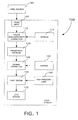
- FIG. 1 shows a block diagram of a liquid crystal on silicon (LCOS) display 100 incorporating color non-uniformity correction.
- the LCOS display 100 can receive video data from a video source 150.
- the video source 150 can be a multimedia device, for example a television tuner, a digital video disk (DVD) player, a video cassette recorder (VCR), a personal video recorder (PVR), a digital broadcast receiver, etc.
- the video source 150 can incorporate a video processor for processing multimedia data and outputting video data in a format compatible with the LCOS display 100.
- the LCOS display 100 can comprise video input 105, color non-uniformity corrector 110 and an associated electrically erasable programmable read-only memory (EEPROM) 115, a frame rate doubler 120, a gamma corrector 125 and associated EEPROM 130, a light engine 135, a high pressure lamp 140 and an LCOS screen 145.
- the video input 105 can receive an input video signal from a video source 150 and forward the input video signal to the color non-uniformity corrector 110.
- the color non-uniformity corrector 110 can incorporate color non-uniformity correction into the input video signal to generate a color corrected video signal.
- EEPROM 115 can store a plurality of red, green, and blue (RGB) correction matrices for correcting the RGB brightness levels of the LCOS screen 145.
- RGB correction matrices can be used for generating non-uniformity color correction and can be created from test measurements made on the LCOS display 100 during or after manufacture of the LCOS display 100.
- Liquid crystals of a light engine 135 can be damaged by DC voltage and may only be driven by AC voltage. Since liquid crystals are responsive to the absolute value of a voltage, pixels can be driven by a first polarity of signal, then an opposite polarity of signal. Accordingly, frame rate doubler 120 can generate two frames of video in opposite polarities from each frame of color corrected video received. Hence, each frame of the color corrected video signal may be displayed twice, once for each polarity. Nevertheless, it should be noted that the LCOS display 100 is not limited to only doubling the frame rate. For example, in another arrangement the frame rate of the color corrected video signal can be increased by any multiple, for example 3X, 4X, 5X, 6X, etc.
- Gamma corrector 125 can apply gamma correction to a color corrected video signal after the frame rate of the signal has been doubled to generate an output video signal.
- Gamma correction is a nonlinear transfer characteristic that corrects for the nonlinear relationship between a liquid crystal imager reflectivity and an applied voltag e. Since gamma correction increases the number of bits in a video signal and a frame rate doubler 120 is typically limited with respect to the amount of video data that can be processed, having the gamma corrector 125 after the frame rate doubler 120 is advantageous.
- EEPROM 130 can store a plurality of gamma correction data associated with the light engine 135.
- Light engine 135 can receive light from high pressure lamp 140.
- the light can be directed into a prism in the light engine where it is divided into the three RGB primary color streams. These three individual streams of light are directed to corresponding light valves, which are highly reflective mirrors contained in the light engine known as imagers, where they can pick up the output video signal as they are reflected off the surface of the imager.
- the three streams of light, each with their specific piece of the same video signal attached, then can be recombined within the prism into a single synchronized video image that is forwarded to the LCOS screen 145 for display.
- the present embodiment is an LCOS display, the present invention is not limited to such and can be used with other liquid crystal displays.
- High RGB correction matrices 205 can be stored in EEPROM 115. Upon system startup the high RGB correction matrices 205 can be transferred from EEPROM 115 to random access memory (RAM) 202.
- High horizontal and vertical interpolator (HHVI) 210 can read high RGB correction matrices 205 from RAM 202.
- the high RGB correction matrices 205 can contain correction values correlating to a limited number of individual pixels in the LCOS screen 145. For example, the correction values in the high RGB correction matrices 205 can be based on required brightness adjustment levels for a video signal having a brightness level of 30%.
- the HHVI 210 can perform horizontal and vertical interpolation on the high RGB correction matrices 205 to generate interpolated high RGB correction matrices (high interpolated matrices).
- the horizontal and vertical interpolation process derives correction values correlating to pixels located between pixels represented in the high RGB correction matrices 205.
- Low RGB correction matrices 215 can be transferred from EEPROM 115 to RAM 112 upon system startup. During system operation the low RGB correction matrices 215 can be supplied to low horizontal and vertical interpolator (LHVI) 220 from RAM 212.
- the low RGB correction matrices 215 can have the same structure as the high RGB correction matrices 205. But the low RGB correction matrices 215 can contain correction reference values for low RGB brightness levels on the LCOS screen 145, for example at a brightness reference level of 10%.
- the LHVI 220 also can perform horizontal and vertical interpolation using the discrete point low RGB correction reference values. Accordingly, the LHVI 220 can generate low RGB interpolation matrices containing low brightness level correction values.
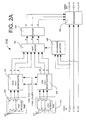
- FIG. 2B illustrates an alternate embodiment for the color non-uniformity corrector 110.
- the color non-uniformity corrector 110 of FIG. 2B further comprises medium RGB correction matrices 275 and a medium horizontal and vertical interpolator (MHVI) 260.
- the medium RGB correction matrices 275 can be provided based on required brightness adjustment levels for a video signal having a brightness level of 20%.
- the medium RGB correction matrices 275 can be supplied to MHVI 260 from RAM 272 to generate medium RGB interpolation matrices.
- the medium RGB correction matrices 275 can have the same structure as the high RGB and low RGB correction matrices 205 and 215.
- the interpolation process performed by HHVI 210, LHVI 220 and MHVI 260 is continuous and RGB correction values are interpolated for pixels as they are required by the soft switch 230.
- the RGB correction matrices can be interpolated once and the resulting high, medium and low RGB interpolation matrices can be stored in a storage, such as an EEPROM, and transferred to RAM upon system startup. The soft switch 230 then can retrieve correction values from the RAM as required without the need for continuous horizontal and vertical interpolation.
- the RGB correction matrices 205, 215 and 275 can be generated from test measurements made on the LCOS d isplay 100 during or after manufacture of the LCOS display 100. Further, additional RGB correction matrices can be provided for various brightness levels.
- Brightness detector 225 can measure the individual brightness of each of the red, blue and green components of each pixel in an incoming video signal and sum these measurements to generate a brightness level for each pixel. For example, if a particular pixel has a red brightness of 10, a green brightness of 20, and a blue brightness of 50, the brightness for the pixel is 80.
- the brightness level for each pixel then can be forwarded to soft switch 230.
- the soft switch 230 can evaluate the brightness level and generate a picture level correction based on the measured brightness data.
- the picture level correction can contain RGB correction values for each pixel. In one arrangement the soft switch 230 can select RGB correction values from the high RGB interpolation matrices, medium RGB interpolation matrices and the low RGB interpolation matrices.
- the soft switch can interpolate values from the RGB interpolation matrices for brightness levels falling between the reference brightness values. For example, values for a high, medium and low brightness thresholds. If the brightness for the pixel is above the high pixel threshold, the soft switch 230 can select the correlating RGB correction values for that pixel from the high RGB interpolation matrices and use these values for the picture level correction. The next pixel may have a brightness below the low brightness threshold. In this case the soft switch 230 can select correlating RGB correction values for that pixel from the low RGB interpolation matrices and uses these correction values for the picture level correction.
- a third pixel may have brightness between the high and medium threshold values.
- the soft switch 230 can interpolate the correlating RGB correction values contained in the high and medium RGB interpolation matrices to derive new RGB correction values for the third pixel in the picture level correction. If a fourth pixel has a brightness value between the medium and low threshold values, the soft switch 230 can interpolate the correlating RGB correction values contained in the medium and low interpolation matrices to derive the fourth pixel's RGB correction values.
- the soft switch can interpolate values from these matrices as well.
- the soft switch can interpolate values from the high and low RGB interpolation matrices for brightness levels falling between the high and low reference values.
- Ditherer 235 can receive the picture level correction from soft switch 230 and dither the picture level correction. Ditherer 235 can dither the picture level correction to reduce the bit resolution of the correction values contained therein. As would be known to one skilled in the art of video processing, dithering approximates a color from a mixture of other colors when the required color is not available. For example, if an 8-bit value is contained in a picture level correction, this 8-bit value can be approximated by two or more 6-bit values, which are provided in a specific sequence. The specific sequence is chosen so that the average of the displayed 6-bit values over a specific period is equal to or nearly equal to the original undithered 8-bit value. For example, if the 8-bit picture correction value is 55.75, the dithered result can be the following sequence displayed over a four-cycle period: 56, 56, 56 and 55.
- a processor 240 can be encoded as an adder and can add the dithered picture level correction to the input video to generate a color corrected output video signal.
- the correction values contained in the picture level correction can be additive values.
- a multiplier can be used for the processor 240.
- the correction values contained in the picture level correction can be multiplication factors.
- RGB correction matrix 300 an example of an RGB correction matrix 300 is shown.
- Three RGB correction matrices can be provided for each reference brightness level, one matrix for each RGB color.
- Discrete points 305 can be equivalently spaced in a grid pattern fitting within the dimensions of the LCOS screen 145.
- the discrete points 305 can be arranged in a grid pattern having 6 rows and 9 columns (6 x 9).
- pixel 315 can be located between pixels 310:1, 310:2, 310:3 and 310:4.
- Pixels 310:1-4 can be located at discrete points 305 and the RGB correction values for pixels 310:1 -4 can be the RGB correction values for their respective discrete points 305.
- the R GB correction value for pixel 315 can be interpolated from the correction values for pixels 310:1-4 using vertical and horizontal interpolation techniques, as would be known to one skilled in the art of video processing.
- the horizontal position of pixel 315 can be noted and horizontal interpolation can be performed on the correction values for pixels 310:1 and 310:2 to derive a first horizontal reference value 320 correlating to the horizontal position of pixel 315.
- Horizontal interpolation then can be performed on the correction values for pixels 310:3 and 310:4 to derive a second horizontal reference value 325 correlating to the horizontal position of pixel 315.
- the vertical position of pixel 315 can be noted and vertical interpolation can be performed on the first and second horizontal reference values 320, 325 correlating to the vertical position of pixel 315, therein deriving a correction value for pixel 315.
- Two fractional bits typically are produced during horizontal and vertical interpolation process.
- the interpolated correction value for pixel 315 can be an 8-bit value, which comprises 6 primary bits and 2 fractional bits. These fractional bits can be retained in the correction value derived for pixel 315 and can be incorporated into a corresponding RGB interpolation matrix, being removed later during the dithering process.
- FIG. 4 shows a flow chart 400 illustrating the method of performing non-uniformity correction using high and low RGB correction marices.
- additional RGB correction matrices can be used as well.
- HHVI 210 and LHVI 220 can interpolate the high RGB correction matrices 205 and the low RGB correction matric es 215, respectively, to generate high and low RGB interpolation matrices.
- the brightness detector 225 can measure the individual brightness of each of the red, blue and green components of each pixel in an incoming video signal and sum these measurements to generate a brightness level for each pixel. The brightness level for each pixel then can be forwarded to the soft switch 230, as shown in step 415.
- RGB correction values for that pixel can be selected from the corresponding correction values in the low RGB interpolated matrices and entered into the picture level correction.
- RGB correction values for that pixel can be selected from the corresponding correction values in the high RGB interpolated matrices and entered into the picture level correction.
- the RGB correction values for that pixel can be interpolated at step 440 from the corresponding correction values in the high and low RGB interpolated matrices and entered into the picture level correction.
- the ditherer 235 can dither the picture level correction to reduce the bit resolution of the correction values contained therein, as previously explained.
- the adder 240 can add picture correction to the input video signal to generate a color corrected output video signal, which can be provided as an output to a light engine at step 455.
- a multiplier also can be used in lieu of adder 240.
Abstract
Description
- This application is a continuation of provisional patent application serial number 60/350,619 filed January 22, 2002 and claims the benefit of the filing date thereof.
- The present invention relates to the field of video display optics, and more particularly to color correction techniques used with display optics.
- LCOS display systems incorporate a high pressure lamp and a light engine for generating a video display in lieu of a cathode ray tube found in traditional video displays. The light engine receives ultra bright light from the high pressure lamp and processes the light through display optics contained within the light engine. Display optics are typically provided for each of the base colors, namely red, green and blue. Variations between the display optics tend to cause color non-uniformity in the LCOS displays. For example, the green optics of a particular LCOS light-engine may be slightly more transmissive in the top left corner. This would produce a green zone in the top left corner of the displayed image. Other LCOS light-engines can have non-uniform zones in other areas of the display. The degree and nature of color non-uniformity varies tremendously from light-engine to light-engine. Notwithstanding, color non-uniformity also changes as a function of pixel brightness. Hence the color non-uniformity can vary as the brightness level of video changes.
- Color non-uniformity correction has been implemented to address color non-uniformity in LCOS displays, however current implementation requires substantial processing resources to implement color non-uniformity correction. Color non-uniformity correction is typically performed after frame rate doubling and gamma correction have been applied to a video signal. To perform color non-uniformity correction after frame rate doubling results in the color non-uniformity correction being applied to twice as much data as contained in an original video signal. Further, gamma correction increases the size of the video data. Hence, performing color non-uniformity correction after gamma correction further increases the amount of video data that must be processed.
- On the other hand, applying color non-uniformity correction prior to frame rate doubling and gamma correction creates an even greater obstacle. Color non-uniformity correction typically increases the amount of video data contained in a video signal as well. However, the frame rate doubler is limited with respect the amount of video data that can be processed. Thus a "bit bottleneck" is created and video data incorporating color non-uniformity correction cannot be adequately processed by the frame rate doubler. Even if the color non-uniformity corrected video could be adequately doubled, the amount of video data handled by the rest of the processing components would be increased. Thus, a need exists for a method and system for color non-uniformity correction prior to increasing the frame rate that overcomes the problems described above.
- The present invention relates to a method and a system for providing video signals to video displays, including the steps of receiving at least one input video signal, generating a non-uniformity color correction which can include generating a dithered non-uniformity color correction, applying the non-uniformity color correction to the input video signal to generate a color corrected video signal, and increasing a frame rate of the color corrected video signal. The method can further include the steps of following the frame rate increase step, applying a gamma correction to the color corrected video signal to generate an output video signal, and providing the output video signal to a light engine of a liquid crystal on silicon video display.
- The step of generating the dithered non-uniformity color correction can include selecting from data storage a plurality of RGB correction matrices, deriving a picture level correction from the plurality of RGB correction matrices, and dithering the picture level correction. Horizontal and vertical pixel interpolation can be performed on the RGB correction matrices after selecting plurality of RGB correction matrices. The step of deriving the picture level correction can include measuring at least one brightness level of the input video signal, selecting for the picture level correction a first RGB correction matrix if the brightness level is within a first range of values, selecting for the picture level correction a second RGB correction matrix if the brightness level is within a second range of values, and interpolating the picture level from the plurality of RGB correction matrices if the brightness level is within a third range of values. The dithered non-uniformity color correction can be added to the input video signal or can multiply the input video signal.
- The system for providing video signals to video displays can include a video input for receiving at least one input video signal, a color non-uniformity corrector for generating a color corrected video signal, a frame rate increaser for increasing the frame rate of the color corrected video signal, and a gamma corrector for applying gamma correction to the color corrected video signal. The color non-uniformity corrector can include a correction generator for generating a non-uniformity color correction signal, a ditherer for dithering the non-uniformity color correction signal, and a processor for incorporating the non-uniformity color correction into the at least one input video signal to generate a color corrected video signal. The processor can be an adder or a multiplier.
- The system can further include at least one data storage for storing a plurality of RGB correction matrices. The data storage can include at least one EEPROM. At least one horizontal and vertical interpolator for performing pixel interpolation on the RGB correction matrices also can be provided. The correction generator can include a brightness detector for detecting the brightness of the input video signal and outputting a brightness level measurement and a soft switch for receiving the brightness level measurement and generating a color correction based on the brightness level measurement. The soft switch can receive at least one RGB correction matrix from at least one of the data storage and the horizontal and vertical interpolator and generate the color correction from the RGB correction matrices. The soft switch can select a first RGB correction matrix if the brightness measurement level is within a first range of values, select a second RGB correction matrix if the brightness measurement level is within a second range of values, and interpolate a plurality of RGB correction matrices if the brightness measurement level is within a third range of values.
-
- FIG. 1 is a block diagram of a liquid crystal on silicon display incorporating color non-uniformity correction in accordance with the present invention.
- FIG. 2A is a block diagram of color non-uniformity correction corrector in accordance with the present invention.
- FIG. 2B is a block diagram of an alternate embodiment for a color non-uniformity correction corrector in accordance with the present invention.
- FIG. 3 is a diagram showing a matrix of discrete points arranged in a grid pattern and having associated correction values in accordance with the present invention.
- FIG. 4 is a flow chart showing the method of performing non-uniformity correction in accordance with the present invention.
-
- FIG. 1 shows a block diagram of a liquid crystal on silicon (LCOS) display 100 incorporating color non-uniformity correction. The LCOS
display 100 can receive video data from avideo source 150. Thevideo source 150 can be a multimedia device, for example a television tuner, a digital video disk (DVD) player, a video cassette recorder (VCR), a personal video recorder (PVR), a digital broadcast receiver, etc. Typically, thevideo source 150 can incorporate a video processor for processing multimedia data and outputting video data in a format compatible with theLCOS display 100. - The
LCOS display 100 can comprisevideo input 105,color non-uniformity corrector 110 and an associated electrically erasable programmable read-only memory (EEPROM) 115, aframe rate doubler 120, agamma corrector 125 and associated EEPROM 130, alight engine 135, a high pressure lamp 140 and anLCOS screen 145. Thevideo input 105 can receive an input video signal from avideo source 150 and forward the input video signal to thecolor non-uniformity corrector 110. - The color non-uniformity
corrector 110 can incorporate color non-uniformity correction into the input video signal to generate a color corrected video signal. EEPROM 115 can store a plurality of red, green, and blue (RGB) correction matrices for correcting the RGB brightness levels of theLCOS screen 145. The RGB correction matrices can be used for generating non-uniformity color correction and can be created from test measurements made on theLCOS display 100 during or after manufacture of theLCOS display 100. - Liquid crystals of a
light engine 135 can be damaged by DC voltage and may only be driven by AC voltage. Since liquid crystals are responsive to the absolute value of a voltage, pixels can be driven by a first polarity of signal, then an opposite polarity of signal. Accordingly,frame rate doubler 120 can generate two frames of video in opposite polarities from each frame of color corrected video received. Hence, each frame of the color corrected video signal may be displayed twice, once for each polarity. Nevertheless, it should be noted that theLCOS display 100 is not limited to only doubling the frame rate. For example, in another arrangement the frame rate of the color corrected video signal can be increased by any multiple, for example 3X, 4X, 5X, 6X, etc. -
Gamma corrector 125 can apply gamma correction to a color corrected video signal after the frame rate of the signal has been doubled to generate an output video signal. Gamma correction is a nonlinear transfer characteristic that corrects for the nonlinear relationship between a liquid crystal imager reflectivity and an applied voltag e. Since gamma correction increases the number of bits in a video signal and aframe rate doubler 120 is typically limited with respect to the amount of video data that can be processed, having thegamma corrector 125 after theframe rate doubler 120 is advantageous.EEPROM 130 can store a plurality of gamma correction data associated with thelight engine 135. -
Light engine 135 can receive light from high pressure lamp 140. The light can be directed into a prism in the light engine where it is divided into the three RGB primary color streams. These three individual streams of light are directed to corresponding light valves, which are highly reflective mirrors contained in the light engine known as imagers, where they can pick up the output video signal as they are reflected off the surface of the imager. The three streams of light, each with their specific piece of the same video signal attached, then can be recombined within the prism into a single synchronized video image that is forwarded to theLCOS screen 145 for display. It should be noted that although the present embodiment is an LCOS display, the present invention is not limited to such and can be used with other liquid crystal displays. - Referring to FIG. 2A, a block diagram of
color non-uniformity corrector 110 is shown. HighRGB correction matrices 205, one for each red, green and blue, can be stored inEEPROM 115. Upon system startup the highRGB correction matrices 205 can be transferred fromEEPROM 115 to random access memory (RAM) 202. High horizontal and vertical interpolator (HHVI) 210 can read highRGB correction matrices 205 fromRAM 202. The highRGB correction matrices 205 can contain correction values correlating to a limited number of individual pixels in theLCOS screen 145. For example, the correction values in the highRGB correction matrices 205 can be based on required brightness adjustment levels for a video signal having a brightness level of 30%. - The
HHVI 210 can perform horizontal and vertical interpolation on the highRGB correction matrices 205 to generate interpolated high RGB correction matrices (high interpolated matrices). The horizontal and vertical interpolation process derives correction values correlating to pixels located between pixels represented in the highRGB correction matrices 205. - Low
RGB correction matrices 215 can be transferred fromEEPROM 115 to RAM 112 upon system startup. During system operation the lowRGB correction matrices 215 can be supplied to low horizontal and vertical interpolator (LHVI) 220 fromRAM 212. The lowRGB correction matrices 215 can have the same structure as the highRGB correction matrices 205. But the lowRGB correction matrices 215 can contain correction reference values for low RGB brightness levels on theLCOS screen 145, for example at a brightness reference level of 10%. As withHHVI 210, theLHVI 220 also can perform horizontal and vertical interpolation using the discrete point low RGB correction reference values. Accordingly, theLHVI 220 can generate low RGB interpolation matrices containing low brightness level correction values. - FIG. 2B illustrates an alternate embodiment for the
color non-uniformity corrector 110. In addition to the elements shown in FIG. 2A, thecolor non-uniformity corrector 110 of FIG. 2B further comprises mediumRGB correction matrices 275 and a medium horizontal and vertical interpolator (MHVI) 260. The mediumRGB correction matrices 275 can be provided based on required brightness adjustment levels for a video signal having a brightness level of 20%. During system operation the mediumRGB correction matrices 275 can be supplied toMHVI 260 fromRAM 272 to generate medium RGB interpolation matrices. The mediumRGB correction matrices 275 can have the same structure as the high RGB and lowRGB correction matrices - In one embodiment the interpolation process performed by
HHVI 210,LHVI 220 andMHVI 260 is continuous and RGB correction values are interpolated for pixels as they are required by thesoft switch 230. In an alternate embodiment the RGB correction matrices can be interpolated once and the resulting high, medium and low RGB interpolation matrices can be stored in a storage, such as an EEPROM, and transferred to RAM upon system startup. Thesoft switch 230 then can retrieve correction values from the RAM as required without the need for continuous horizontal and vertical interpolation. - As previously noted, the
RGB correction matrices LCOS d isplay 100 during or after manufacture of theLCOS display 100. Further, additional RGB correction matrices can be provided for various brightness levels. -
Brightness detector 225 can measure the individual brightness of each of the red, blue and green components of each pixel in an incoming video signal and sum these measurements to generate a brightness level for each pixel. For example, if a particular pixel has a red brightness of 10, a green brightness of 20, and a blue brightness of 50, the brightness for the pixel is 80. The brightness level for each pixel then can be forwarded tosoft switch 230. Thesoft switch 230 can evaluate the brightness level and generate a picture level correction based on the measured brightness data. The picture level correction can contain RGB correction values for each pixel. In one arrangement thesoft switch 230 can select RGB correction values from the high RGB interpolation matrices, medium RGB interpolation matrices and the low RGB interpolation matrices. - The soft switch can interpolate values from the RGB interpolation matrices for brightness levels falling between the reference brightness values. For example, values for a high, medium and low brightness thresholds. If the brightness for the pixel is above the high pixel threshold, the
soft switch 230 can select the correlating RGB correction values for that pixel from the high RGB interpolation matrices and use these values for the picture level correction. The next pixel may have a brightness below the low brightness threshold. In this case thesoft switch 230 can select correlating RGB correction values for that pixel from the low RGB interpolation matrices and uses these correction values for the picture level correction. - In our example of FIG. 2B, a third pixel may have brightness between the high and medium threshold values. In this case the
soft switch 230 can interpolate the correlating RGB correction values contained in the high and medium RGB interpolation matrices to derive new RGB correction values for the third pixel in the picture level correction. If a fourth pixel has a brightness value between the medium and low threshold values, thesoft switch 230 can interpolate the correlating RGB correction values contained in the medium and low interpolation matrices to derive the fourth pixel's RGB correction values. - As previously noted, additional RGB interpolation matrices can be provided. Accordingly, the soft switch can interpolate values from these matrices as well. When only two RGB interpolation matrices are provided, as in the case of FIG. 2A, the soft switch can interpolate values from the high and low RGB interpolation matrices for brightness levels falling between the high and low reference values.
-
Ditherer 235 can receive the picture level correction fromsoft switch 230 and dither the picture level correction.Ditherer 235 can dither the picture level correction to reduce the bit resolution of the correction values contained therein. As would be known to one skilled in the art of video processing, dithering approximates a color from a mixture of other colors when the required color is not available. For example, if an 8-bit value is contained in a picture level correction, this 8-bit value can be approximated by two or more 6-bit values, which are provided in a specific sequence. The specific sequence is chosen so that the average of the displayed 6-bit values over a specific period is equal to or nearly equal to the original undithered 8-bit value. For example, if the 8-bit picture correction value is 55.75, the dithered result can be the following sequence displayed over a four-cycle period: 56, 56, 56 and 55. - A
processor 240 can be encoded as an adder and can add the dithered picture level correction to the input video to generate a color corrected output video signal. In this embodiment the correction values contained in the picture level correction can be additive values. Alternatively, a multiplier can be used for theprocessor 240. In this second embodiment the correction values contained in the picture level correction can be multiplication factors. - Referring to FIG. 3, an example of an
RGB correction matrix 300 is shown. Three RGB correction matrices can be provided for each reference brightness level, one matrix for each RGB color.Discrete points 305 can be equivalently spaced in a grid pattern fitting within the dimensions of theLCOS screen 145. For example, thediscrete points 305 can be arranged in a grid pattern having 6 rows and 9 columns (6 x 9). For example,pixel 315 can be located between pixels 310:1, 310:2, 310:3 and 310:4. Pixels 310:1-4 can be located atdiscrete points 305 and the RGB correction values for pixels 310:1 -4 can be the RGB correction values for their respectivediscrete points 305. The R GB correction value forpixel 315 can be interpolated from the correction values for pixels 310:1-4 using vertical and horizontal interpolation techniques, as would be known to one skilled in the art of video processing. - For example, the horizontal position of
pixel 315 can be noted and horizontal interpolation can be performed on the correction values for pixels 310:1 and 310:2 to derive a firsthorizontal reference value 320 correlating to the horizontal position ofpixel 315. Horizontal interpolation then can be performed on the correction values for pixels 310:3 and 310:4 to derive a secondhorizontal reference value 325 correlating to the horizontal position ofpixel 315. Next, the vertical position ofpixel 315 can be noted and vertical interpolation can be performed on the first and second horizontal reference values 320, 325 correlating to the vertical position ofpixel 315, therein deriving a correction value forpixel 315. Two fractional bits typically are produced during horizontal and vertical interpolation process. For example, if the correction values for pixels 310:1-4 are 6-bit values, the interpolated correction value forpixel 315 can be an 8-bit value, which comprises 6 primary bits and 2 fractional bits. These fractional bits can be retained in the correction value derived forpixel 315 and can be incorporated into a corresponding RGB interpolation matrix, being removed later during the dithering process. - FIG. 4 shows a
flow chart 400 illustrating the method of performing non-uniformity correction using high and low RGB correction marices. As previously noted, additional RGB correction matrices can be used as well. Atstep 405,HHVI 210 andLHVI 220 can interpolate the highRGB correction matrices 205 and the low RGB correction matric es 215, respectively, to generate high and low RGB interpolation matrices. Atstep 410 thebrightness detector 225 can measure the individual brightness of each of the red, blue and green components of each pixel in an incoming video signal and sum these measurements to generate a brightness level for each pixel. The brightness level for each pixel then can be forwarded to thesoft switch 230, as shown instep 415. - Referring to decision block 420 and step 425, if the brightness level for a pixel is less than or equal to a first value, X, then RGB correction values for that pixel can be selected from the corresponding correction values in the low RGB interpolated matrices and entered into the picture level correction. Referring to decision block 430 and step 435, if the brightness level for a pixel is greater than or equal to a second value, Y, then RGB correction values for that pixel can be selected from the corresponding correction values in the high RGB interpolated matrices and entered into the picture level correction. If the brightness level for the pixel is greater than X and less than Y, then the RGB correction values for that pixel can be interpolated at
step 440 from the corresponding correction values in the high and low RGB interpolated matrices and entered into the picture level correction. - At
step 445 theditherer 235 can dither the picture level correction to reduce the bit resolution of the correction values contained therein, as previously explained. Atstep 450 theadder 240 can add picture correction to the input video signal to generate a color corrected output video signal, which can be provided as an output to a light engine atstep 455. As previously noted, a multiplier also can be used in lieu ofadder 240. - It should be understood that the examples and embodiments described herein are for illustrative purposes only and that various modifications or changes in light thereof can be suggested by persons skilled in the art and are to be included within the spirit and purview of this application. The invention can take many other specific forms without departing from the spirit or essential attributes thereof for an indication of the scope of the invention.
Claims (23)
- A method for color correcting video signals in video displays, comprising the steps of:receiving (in block 105) at least one input video signal;generating a color correction; andincreasing a frame rate of said color corrected video signal, characterized by:after said receiving step, generating (step 445) a dithered non-uniformity color correction;after said generating step, applying (step 450) said dithered non - uniformity color correction to said input video signal to generate a color corrected video signal; andafter said applying step, increasing a frame rate (in block 120) of said color corrected video signal.
- The method of claim 1, further characterized by the steps of:following the frame rate increasing step, applying a gamma correction (in block 125) to said color corrected video signal to generate an output video signal; andproviding said output video signal to a light engine (step 455) of a liquid crystal on silicon video display (in block 135).
- The method of claim 1, characterized in that said step of generating the dithered non-uniformity color correction comprises:selecting (steps 420, 430) from a data storage a plurality of RGB correction matrices;deriving (step 440) a picture level correction from said plurality of RGB correction matrices; anddithering (step 445) said picture level correction.
- The method of claim 3, characterized in that said deriving the picture level correction step comprises:measuring (steps 420, 430) at least one brightness level of said input video signal; andinterpolating (in blocks 210, 220, 260) said picture level from said plurality of RGB correction matrices based at least upon said at least one brightness level.
- The method of claim 3, characterized in that said deriving the picture level correction step comprises:measuring at least one brightness level of said input video signal; andselecting for said picture level correction at least one of said plurality of RGB correction matrices based at least upon said at least one brightness level.
- The method of claim 3, characterized in that said deriving the picture level correction step comprises:measuring at least one brightness level of said input video signal;selecting (step 420) for said picture level correction a first RGB correction matrix if said brightness level is within a first range of values; andselecting (step 430) for said picture level correction a second RGB correction matrix if said brightness level is within a second range of values.
- The method of claim 6, characterized in that said deriving the picture level correction step further comprises interpolating said picture level from said plurality of RGB correction matrices if said brightness level is within a third range of values (block 225 in Fig. 2B).
- The method of claim 3, further characterized by the step of applying horizontal and vertical pixel interpolation on said RGB correction matrices after said selecting the plurality of RGB correction matrices step.
- The method of claim 1, characterized in that said applying said dithered non-uniformity color correction to said input video signal step comprises adding said dithered non-uniformity color correction to said input video signal.
- The method of claim 1, characterized in that said applying said dithered non-uniformity color correction to said input video signal step comprises multiplying said input video signal by said dithered non-uniformity color correction.
- The method of claim 1, characterized in that said step of generating a dithered non-uniformity color correction comprises:selecting from a data storage at least one RGB correction matrix;applying horizontal and vertical pixel interpolation on said RGB correction matrix to generate a pixel interpolated RGB correction matrix;deriving a picture level correction from said pixel interpolated RGB correction matrix; anddithering said picture level correction.
- A method for color correcting video signals in video displays, comprising the steps of:receiving at least one input video signal;after said receiving step, generating a non-uniformity color correction;after said generating step, applying said non-uniformity color correction to said input video signal to generate a color corrected video signal; andafter said applying step, increasing a frame rate of said color corrected video signal.
- A system for color correcting video signals for video displays, comprising:a video input (105) for receiving at least one input video signal;a color non-uniformity corrector (110) for generating a color corrected video signal; anda frame rate increaser (120) for increasing the frame rate of said color corrected video signal.
- The system of claim 13, further characterized by a gamma corrector (125) for applying gamma correction to said color corrected video signal.
- The system of claim 13, characterized in that said color non-uniformity corrector comprises:a correction generator (202, 212, 272; 210, 220, 260; 225, 230) for generating a non-uniformity color correction signal;a ditherer (235) for dithering said non-uniformity color correction signal; anda processor (240) for incorporating said non-uniformity color correction into said at least one input video signal to generate a color corrected video signal.
- The system of claim 15 characterized in that said processor is an adder.
- The system of claim 15 characterized in that said processor is a multiplier.
- The system of claim 15, further characterized by at least one data storage (202, 212, 272) for storing a plurality of RGB correction matrices.
- The system of claim 18 characterized in that said at least one data storage comprises at least one EEPROM.
- The system of claim 15 further characterized by at least one horizontal and vertical interpolator (210, 220, 260) for performing pixel interpolation on said RGB correction matrices.
- The system of claim 15 characterized in that said correction generator comprises:a brightness detector (225) for detecting the brightness of said input video signal and outputting a brightness level measurement; anda soft switch (235) for receiving said brightness level measurement and generating a color correction based on said brightness level measurement.
- The system of claim 21 further characterized by:wherein said soft switch receives at least one RGB correction matrix from at least one of said data storage and said horizontal and vertical interpolator and generates said color correction from said at least one RGB correction matrix.at least one of a data storage (202, 212, 272) and a horizontal and vertical interpolator (210, 220, 260);
- The system of claim 22 characterized in that:said soft switch selects a first RGB correction matrix if said brightness measurement level is within a first range of values:said soft switch selects a second RGB correction matrix if said brightness measurement level is within a second range of values; andsaid soft switch interpolates a plurality of RGB correction matrices if said brightness measurement level is within a third range of values.
Applications Claiming Priority (4)
| Application Number | Priority Date | Filing Date | Title |
|---|---|---|---|
| US350619P | 2002-01-21 | ||
| US35061902P | 2002-01-22 | 2002-01-22 | |
| US142573 | 2002-05-09 | ||
| US10/142,573 US7253845B2 (en) | 2002-01-22 | 2002-05-09 | Color non-uniformity correction for LCOS |
Publications (2)
| Publication Number | Publication Date |
|---|---|
| EP1330131A2 true EP1330131A2 (en) | 2003-07-23 |
| EP1330131A3 EP1330131A3 (en) | 2004-05-19 |
Family
ID=26840228
Family Applications (1)
| Application Number | Title | Priority Date | Filing Date |
|---|---|---|---|
| EP03290113A Withdrawn EP1330131A3 (en) | 2002-01-21 | 2003-01-16 | Color non-uniformity correction for lcos |
Country Status (7)
| Country | Link |
|---|---|
| US (1) | US7253845B2 (en) |
| EP (1) | EP1330131A3 (en) |
| JP (1) | JP4902933B2 (en) |
| KR (1) | KR100950166B1 (en) |
| CN (1) | CN100477803C (en) |
| MX (1) | MXPA03000536A (en) |
| MY (1) | MY141565A (en) |
Cited By (6)
| Publication number | Priority date | Publication date | Assignee | Title |
|---|---|---|---|---|
| EP1503333A1 (en) * | 2003-08-01 | 2005-02-02 | Sony International (Europe) GmbH | Correction of non-uniform image display |
| WO2005015533A1 (en) * | 2003-08-11 | 2005-02-17 | Koninklijke Philips Electronics, N.V. | Uniformity correction of black and white states in liquid crystal displays |
| WO2007008405A1 (en) * | 2005-07-12 | 2007-01-18 | Eastman Kodak Company | Black level uniformity correction method |
| KR100950166B1 (en) * | 2002-01-22 | 2010-03-30 | 톰슨 라이센싱 에스.에이. | Color non-uniformity correction for LCOS |
| WO2012030719A3 (en) * | 2010-08-30 | 2012-04-26 | Qualcomm Incorporated | Adaptive color correction for display with backlight modulation |
| GB2569791A (en) * | 2017-12-21 | 2019-07-03 | Displaylink Uk Ltd | Display system with defect correction |
Families Citing this family (23)
| Publication number | Priority date | Publication date | Assignee | Title |
|---|---|---|---|---|
| JP4260746B2 (en) * | 2002-06-26 | 2009-04-30 | パナソニック株式会社 | Characteristic correction apparatus, imaging reproduction system, characteristic correction method, and program recording medium |
| JP2004159191A (en) * | 2002-11-07 | 2004-06-03 | Seiko Epson Corp | Conversion of frame rate in accordance with image data |
| KR20050118224A (en) * | 2003-04-03 | 2005-12-15 | 코닌클리즈케 필립스 일렉트로닉스 엔.브이. | Runtime configurable virtual video pipeline |
| FR2869744A1 (en) * | 2004-04-29 | 2005-11-04 | Thomson Licensing Sa | METHOD FOR TRANSMITTING DIGITAL DATA PACKETS AND APPARATUS IMPLEMENTING THE METHOD |
| US7295192B2 (en) * | 2004-05-04 | 2007-11-13 | Au Optronics Corporation | Compensating color shift of electro-luminescent displays |
| KR100744111B1 (en) | 2004-11-12 | 2007-08-01 | 삼성전자주식회사 | Compensation device for gray element of image signal |
| JP4840740B2 (en) * | 2004-12-01 | 2011-12-21 | 株式会社メガチップス | Pixel interpolation method and image determination method |
| US20070205969A1 (en) * | 2005-02-23 | 2007-09-06 | Pixtronix, Incorporated | Direct-view MEMS display devices and methods for generating images thereon |
| JP2006259372A (en) * | 2005-03-17 | 2006-09-28 | Victor Co Of Japan Ltd | Color irregularity correction apparatus |
| CN100437744C (en) * | 2005-12-21 | 2008-11-26 | 比亚迪股份有限公司 | Color regulating method and system of display terminal |
| US20080068293A1 (en) * | 2006-09-19 | 2008-03-20 | Tvia, Inc. | Display Uniformity Correction Method and System |
| US20080068396A1 (en) * | 2006-09-19 | 2008-03-20 | Tvia, Inc. | Gamma Uniformity Correction Method and System |
| US20080068404A1 (en) * | 2006-09-19 | 2008-03-20 | Tvia, Inc. | Frame Rate Controller Method and System |
| US20080266459A1 (en) * | 2007-04-26 | 2008-10-30 | Mark Butterworth | Multiple format video display |
| JP2009003180A (en) * | 2007-06-21 | 2009-01-08 | Nanao Corp | Display method and display device |
| JP4922091B2 (en) * | 2007-07-23 | 2012-04-25 | ルネサスエレクトロニクス株式会社 | Video signal processing device, video signal processing method, and display device |
| JP5342125B2 (en) * | 2007-10-11 | 2013-11-13 | セミコンダクター・コンポーネンツ・インダストリーズ・リミテッド・ライアビリティ・カンパニー | Video signal processing apparatus for dithering video signals |
| US8295359B2 (en) * | 2008-03-18 | 2012-10-23 | Auratechnic, Inc. | Reducing differentials in visual media |
| US20100079503A1 (en) * | 2008-09-30 | 2010-04-01 | Texas Instruments Incorporated | Color Correction Based on Light Intensity in Imaging Systems |
| US9014504B2 (en) * | 2012-05-31 | 2015-04-21 | Apple Inc. | Systems and methods for highlight recovery in an image signal processor |
| CN104599632B (en) * | 2015-01-05 | 2017-10-27 | 昆山国显光电有限公司 | Improve the method and device of OLED display brightness uniformities |
| US20160381253A1 (en) * | 2015-06-26 | 2016-12-29 | Mediatek Inc. | Image processor comprising local color processing circuits and associated image processing method for adjusting blue light strength of image |
| CN105654891B (en) * | 2016-04-05 | 2018-06-26 | 京东方科技集团股份有限公司 | A kind of method, apparatus and display panel for obtaining mura offsets |
Citations (2)
| Publication number | Priority date | Publication date | Assignee | Title |
|---|---|---|---|---|
| WO1995026611A1 (en) * | 1994-03-29 | 1995-10-05 | Radius Inc. | Method and apparatus for dynamic purity correction |
| EP1061500A2 (en) * | 1999-06-18 | 2000-12-20 | Seiko Epson Corporation | Color correction in image display |
Family Cites Families (16)
| Publication number | Priority date | Publication date | Assignee | Title |
|---|---|---|---|---|
| JPS59224861A (en) * | 1983-06-06 | 1984-12-17 | Canon Inc | Color copying machine |
| US5260787A (en) * | 1991-05-14 | 1993-11-09 | Sony Electronics Inc. | Film-to-video frame image conversion apparatus and method for selectively identifying video fields and frames |
| US5255083A (en) * | 1991-06-05 | 1993-10-19 | Sony Corporation Of America | Digital color correction system and method |
| US5155586A (en) * | 1991-08-19 | 1992-10-13 | Sony Corporation Of America | Method and apparatus for flare correction |
| GB9322260D0 (en) * | 1993-10-28 | 1993-12-15 | Pandora Int Ltd | Digital video processor |
| JPH09146496A (en) * | 1995-11-17 | 1997-06-06 | Nec Corp | Projector with color irregularity and luminance unevenness correcting circuit |
| US6226034B1 (en) * | 1997-05-06 | 2001-05-01 | Roper Scientificomasd, Inc. | Spatial non-uniformity correction of a color sensor |
| JPH1185110A (en) * | 1997-09-09 | 1999-03-30 | Sony Corp | Display device and display method |
| US6456340B1 (en) * | 1998-08-12 | 2002-09-24 | Pixonics, Llc | Apparatus and method for performing image transforms in a digital display system |
| JP3460601B2 (en) * | 1998-11-26 | 2003-10-27 | 日本ビクター株式会社 | Video signal processing circuit and video signal processing method for matrix type display device |
| JP2000221925A (en) * | 1999-01-29 | 2000-08-11 | Matsushita Electric Ind Co Ltd | Liquid crystal driving circuit |
| JP3661584B2 (en) * | 2000-01-28 | 2005-06-15 | セイコーエプソン株式会社 | ELECTRO-OPTICAL DEVICE, IMAGE PROCESSING CIRCUIT, IMAGE DATA CORRECTION METHOD, AND ELECTRONIC DEVICE |
| JP4518623B2 (en) | 2000-05-10 | 2010-08-04 | 三菱電機株式会社 | Projection type LCD |
| JP2001343950A (en) * | 2000-06-02 | 2001-12-14 | Sony Corp | Image display device and method |
| KR100750929B1 (en) * | 2001-07-10 | 2007-08-22 | 삼성전자주식회사 | Liquid crystal display with a function of color correction, and apparatus and method for driving thereof |
| US7253845B2 (en) * | 2002-01-22 | 2007-08-07 | Thomson Licensing | Color non-uniformity correction for LCOS |
-
2002
- 2002-05-09 US US10/142,573 patent/US7253845B2/en not_active Expired - Lifetime
-
2003
- 2003-01-16 EP EP03290113A patent/EP1330131A3/en not_active Withdrawn
- 2003-01-17 MX MXPA03000536A patent/MXPA03000536A/en active IP Right Grant
- 2003-01-20 MY MYPI20030179A patent/MY141565A/en unknown
- 2003-01-20 JP JP2003011559A patent/JP4902933B2/en not_active Expired - Fee Related
- 2003-01-21 KR KR1020030003927A patent/KR100950166B1/en not_active IP Right Cessation
- 2003-01-21 CN CNB031029140A patent/CN100477803C/en not_active Expired - Fee Related
Patent Citations (2)
| Publication number | Priority date | Publication date | Assignee | Title |
|---|---|---|---|---|
| WO1995026611A1 (en) * | 1994-03-29 | 1995-10-05 | Radius Inc. | Method and apparatus for dynamic purity correction |
| EP1061500A2 (en) * | 1999-06-18 | 2000-12-20 | Seiko Epson Corporation | Color correction in image display |
Cited By (11)
| Publication number | Priority date | Publication date | Assignee | Title |
|---|---|---|---|---|
| KR100950166B1 (en) * | 2002-01-22 | 2010-03-30 | 톰슨 라이센싱 에스.에이. | Color non-uniformity correction for LCOS |
| EP1503333A1 (en) * | 2003-08-01 | 2005-02-02 | Sony International (Europe) GmbH | Correction of non-uniform image display |
| US7365800B2 (en) | 2003-08-01 | 2008-04-29 | Sony Deutschland Gmbh | Method for pre-processing image data |
| WO2005015533A1 (en) * | 2003-08-11 | 2005-02-17 | Koninklijke Philips Electronics, N.V. | Uniformity correction of black and white states in liquid crystal displays |
| WO2007008405A1 (en) * | 2005-07-12 | 2007-01-18 | Eastman Kodak Company | Black level uniformity correction method |
| US7605785B2 (en) | 2005-07-12 | 2009-10-20 | Eastman Kodak Company | Black level uniformity correction method |
| WO2012030719A3 (en) * | 2010-08-30 | 2012-04-26 | Qualcomm Incorporated | Adaptive color correction for display with backlight modulation |
| WO2012030718A3 (en) * | 2010-08-30 | 2012-04-26 | Qualcomm Incorporated | Calibration of display for color response shifts at different luminance settings and for cross-talk between channels |
| US9478173B2 (en) | 2010-08-30 | 2016-10-25 | Qualcomm Incorporated | Adaptive color correction for display with backlight modulation |
| GB2569791A (en) * | 2017-12-21 | 2019-07-03 | Displaylink Uk Ltd | Display system with defect correction |
| GB2569791B (en) * | 2017-12-21 | 2022-10-05 | Displaylink Uk Ltd | Display system with defect correction |
Also Published As
| Publication number | Publication date |
|---|---|
| MY141565A (en) | 2010-05-14 |
| CN1440205A (en) | 2003-09-03 |
| KR20030063221A (en) | 2003-07-28 |
| CN100477803C (en) | 2009-04-08 |
| US20030137606A1 (en) | 2003-07-24 |
| US7253845B2 (en) | 2007-08-07 |
| KR100950166B1 (en) | 2010-03-30 |
| EP1330131A3 (en) | 2004-05-19 |
| JP2003308053A (en) | 2003-10-31 |
| MXPA03000536A (en) | 2004-09-03 |
| JP4902933B2 (en) | 2012-03-21 |
Similar Documents
| Publication | Publication Date | Title |
|---|---|---|
| US7253845B2 (en) | Color non-uniformity correction for LCOS | |
| US7738037B2 (en) | Method and apparatus for eliminating motion artifacts from video | |
| JP5153336B2 (en) | Method for reducing motion blur in a liquid crystal cell | |
| US20010033260A1 (en) | Liquid crystal display device for displaying video data | |
| US7440006B2 (en) | System for gracefully aging inactive areas of a video display | |
| US8655065B2 (en) | Image processing device using adding module for adding error diffusion value or error diffusion seed | |
| KR960012929A (en) | Error Diffusion Filters for DMD Displays | |
| WO2008036689A2 (en) | Frame rate control method and system | |
| US5216493A (en) | Multipoint digital automatic white balance for a video system | |
| KR100525143B1 (en) | Liquid crystal display method | |
| US20080158431A1 (en) | System and Method for Improving Video Image Sharpness | |
| US7345713B2 (en) | Video display apparatus for correcting luminance difference between display pixels | |
| EP1045594A2 (en) | Programmable real-time image processing | |
| EP1195048A1 (en) | Image enhancement system | |
| JP3731666B2 (en) | Image processing system, projector, program, information storage medium, and image processing method | |
| JPH1013849A (en) | Gamma correction system for pdp | |
| JP3251487B2 (en) | Image processing device | |
| JP2002108298A (en) | Digital signal processing circuit, its processing method, display device, liquid crystal display device and liquid crystal projector | |
| JP5057053B2 (en) | Gamma switching device and method | |
| WO2003083559A2 (en) | Color non-uniformity alignment for light engines | |
| GB2341678A (en) | Testing display image quality with a camera | |
| KR100508306B1 (en) | An Error Diffusion Method based on Temporal and Spatial Dispersion of Minor Pixels on Plasma Display Panel | |
| JP2938264B2 (en) | Liquid crystal display | |
| FR2838272A1 (en) | METHOD AND DEVICE FOR CORRECTING ROTATION OF A VIDEO DISPLAY | |
| JPH0294868A (en) | Video correction circuit |
Legal Events
| Date | Code | Title | Description |
|---|---|---|---|
| PUAI | Public reference made under article 153(3) epc to a published international application that has entered the european phase |
Free format text: ORIGINAL CODE: 0009012 |
|
| AK | Designated contracting states |
Designated state(s): AT BE BG CH CY CZ DE DK EE ES FI FR GB GR HU IE IT LI LU MC NL PT SE SI SK TR |
|
| AX | Request for extension of the european patent |
Extension state: AL LT LV MK RO |
|
| PUAL | Search report despatched |
Free format text: ORIGINAL CODE: 0009013 |
|
| AK | Designated contracting states |
Kind code of ref document: A3 Designated state(s): AT BE BG CH CY CZ DE DK EE ES FI FR GB GR HU IE IT LI LU MC NL PT SE SI SK TR |
|
| AX | Request for extension of the european patent |
Extension state: AL LT LV MK RO |
|
| 17P | Request for examination filed |
Effective date: 20041110 |
|
| AKX | Designation fees paid |
Designated state(s): DE FR GB IT |
|
| RAP1 | Party data changed (applicant data changed or rights of an application transferred) |
Owner name: THOMSON LICENSING |
|
| RAP1 | Party data changed (applicant data changed or rights of an application transferred) |
Owner name: THOMSON LICENSING |
|
| 17Q | First examination report despatched |
Effective date: 20100715 |
|
| STAA | Information on the status of an ep patent application or granted ep patent |
Free format text: STATUS: THE APPLICATION IS DEEMED TO BE WITHDRAWN |
|
| 18D | Application deemed to be withdrawn |
Effective date: 20110126 |