EP1330111A2 - Automatic image quality evaluation and correction technique - Google Patents
Automatic image quality evaluation and correction technique Download PDFInfo
- Publication number
- EP1330111A2 EP1330111A2 EP03075022A EP03075022A EP1330111A2 EP 1330111 A2 EP1330111 A2 EP 1330111A2 EP 03075022 A EP03075022 A EP 03075022A EP 03075022 A EP03075022 A EP 03075022A EP 1330111 A2 EP1330111 A2 EP 1330111A2
- Authority
- EP
- European Patent Office
- Prior art keywords
- image
- gray scale
- noise
- binary
- binary image
- Prior art date
- Legal status (The legal status is an assumption and is not a legal conclusion. Google has not performed a legal analysis and makes no representation as to the accuracy of the status listed.)
- Granted
Links
Images


Classifications
-
- H—ELECTRICITY
- H04—ELECTRIC COMMUNICATION TECHNIQUE
- H04N—PICTORIAL COMMUNICATION, e.g. TELEVISION
- H04N1/00—Scanning, transmission or reproduction of documents or the like, e.g. facsimile transmission; Details thereof
- H04N1/40—Picture signal circuits
- H04N1/403—Discrimination between the two tones in the picture signal of a two-tone original
-
- G—PHYSICS
- G06—COMPUTING; CALCULATING OR COUNTING
- G06T—IMAGE DATA PROCESSING OR GENERATION, IN GENERAL
- G06T7/00—Image analysis
- G06T7/0002—Inspection of images, e.g. flaw detection
-
- G—PHYSICS
- G06—COMPUTING; CALCULATING OR COUNTING
- G06T—IMAGE DATA PROCESSING OR GENERATION, IN GENERAL
- G06T2207/00—Indexing scheme for image analysis or image enhancement
- G06T2207/30—Subject of image; Context of image processing
- G06T2207/30168—Image quality inspection
Definitions
- the digital output of a scanned paper document is often represented and stored in binary (Black and White) form because of greater efficiency in storage and transmission, particularly for textual images.
- binary Black and White
- the capture of a binary image requires an image thresholding process installed in a scanner, which converts digital gray scale signals captured by a CCD sensor (usually, 8 bits per pixel) into binary signals (1 bit per pixel). Since an image thresholding is an image data reduction process, it often results in unwanted image artifacts or image information loss, such as speckle noises in the document background or loss of low contrast characters.
- image thresholding is an image data reduction process, it often results in unwanted image artifacts or image information loss, such as speckle noises in the document background or loss of low contrast characters.
- there are numerous adaptive thresholding techniques for producing an optimal quality binary image are numerous adaptive thresholding techniques for producing an optimal quality binary image.
- an adaptive thresholding technique has yet to be found that automatically produces a clean, readable binary image for every captured gray scale image in a batch of paper documents due to variations of paper background and content.
- the production document scanning often requires intensive labor in the form of visual image quality inspection warranting that every captured binary image is readable.
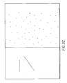
- Figure 3B is an example of noise dot structures before image dilation in a binary image.
- Figure 3E is an example of noise feature calculation in a binary image.
- Figure 4B is the table containing the calculated noise levels for different thresholded images produced by various input parameters (contrast threshold (GT), intensity threshold (IT)).
- CT contrast threshold
- IT intensity threshold
- the multi-windowing technique for thresholding an image using local image properties as described in U.S. Patent No. 5,583,659, the disclosure of which is hereby incorporated by reference, is applied to convert a gray scale image into a binary image.
- the thresholding technique calculates the threshold value for every pixel in an image based on the local image properties surrounding the pixel.
- the threshold value is then applied to turn the gray value of a pixel into bi-level value (black or white).
- the block diagram of the thresholding technique is summarized in Figure 2.
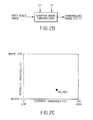
- the operation of the technique requires a user to supply a contrast threshold value (CT) and an intensity threshold value (IT) as shown in Figure 2A.
- CT contrast threshold value
- IT intensity threshold value
- the image quality of a thresholded image is determined by the input of the two threshold values (CT and IT).
- a thresholded image (CT, IT) as shown in Figure 2A means that the image quality of a thresholded image is a function of (CT, IT).
- the image quality of a thresholded image is evaluated by two factors: text readability (no image information loss) and smoothness of the white background (noise free on image background).
- the CT value controls the sensitivity of detecting thin, light text and line arts, and the it value accounts for the threshold of a uniform gray region. Assume that the CT value is normalized to the values in the range of 0 and 100 and the it value is between 0 and 255 as shown in Figure 2B.
- the CT value is often chosen to be sensitive enough for extracting all image information such as light text, thin lines, ...
- the image dilation operation is to expand the region of black dots by a local neighborhood operation as shown in Figure 3A.
- the dilation operation is required because in some documents the text is printed with dot-matrix. The dilation operation connects the adjacent small dots into line segments so that the noise dots and the dots belonging to dot-matrix characters becomes distinguishable.
- Figure 3B displays a binary image before image dilation.
- the number and size of the black dots in the left-handed side of the image is identical to the one in the right-handed side. If the number (or the area) of the noise dots is taken as a feature to evaluate level of noise, the feature will fail to differentiate the image patterns in both sides. However, after image dilation is applied, the original dotted pattern is turned into two straight line segments in the left-handed side as shown in Figure 3C.
- the dispersed noise patterns in the right handed side of the image stays the same except the enlarged noise dots. Hence, the number of noise dots becomes a useful feature in extracting real noise dots in the evaluation of noise level in the dilated binary image.
- FIG. 3D depicts the processing steps of noise measurement on the dilated binary image.
- a contour tracing method see reference in U.S. Patent No. 5,974,199, the disclosure of which is hereby incorporated by reference
- the contour pixels are extracted either in a sequence of clockwise or counterclockwise.
- the contours extracted in the order of clockwise are the outer contour (or black object contours), and the contours extracted in the order of counterclockwise are the inner contours (or white object contours).
- a size threshold (T s ) is applied to reject the large contour components whose size is too large to be considered as noise dots.
- the numbers of the remaining small contours are counted for black noise dots (NB) and white noise dots (NW), respectively, and the total noise area (NA) for black noise dots is calculated.
- the normalized noise area (R) is the ratio of NA value over the document area (DA) and is taken as the image noise index (INI).
- the NB and NW values are used to differentiate the white background from the black background. When the NB is greater than the NW, it indicates that the image has a white background. A large NW value then indicates that the background is black. This occurs when there is a con-tone image or large dark gray area existed in the document.
- Figure 3E is an example of the calculation of noise features.
- NW white noise dots
- the image noise index (INI) is used to judge the noise level of a binary image.
- ITH a specified threshold
- the image is considered as good binary image. That means the binary image is legible and the background is clean.
- ITH a specified threshold
- it is classified as a noise binary image.
- the document is required to rescan or the gray scale image is retrieved if available for automatic image quality correction.
Landscapes
- Engineering & Computer Science (AREA)
- Multimedia (AREA)
- Signal Processing (AREA)
- Quality & Reliability (AREA)
- Computer Vision & Pattern Recognition (AREA)
- Physics & Mathematics (AREA)
- General Physics & Mathematics (AREA)
- Theoretical Computer Science (AREA)
- Image Processing (AREA)
- Image Analysis (AREA)
- Facsimile Image Signal Circuits (AREA)
- Accessory Devices And Overall Control Thereof (AREA)
Abstract
Description
- The invention relates to a process and system for automating the image quality inspection and correction for scanned documents which previously required a human operator. The process and system for each and every scanned and thresholded image performs an automatic evaluation through a binary image quality detection system which generates an image noise index indicative of the amount of image artifacts or image loss. When a poor quality scanned page is detected, e.g., too much speckle noise is present, the gray scale image is retrieved or the image is rescanned in gray scale. The gray scale image then automatically undergoes an image quality correction process to produce a clean, readable binary image.
- In a production scanning environment, the digital output of a scanned paper document is often represented and stored in binary (Black and White) form because of greater efficiency in storage and transmission, particularly for textual images. The capture of a binary image requires an image thresholding process installed in a scanner, which converts digital gray scale signals captured by a CCD sensor (usually, 8 bits per pixel) into binary signals (1 bit per pixel). Since an image thresholding is an image data reduction process, it often results in unwanted image artifacts or image information loss, such as speckle noises in the document background or loss of low contrast characters. In the prior art, there are numerous adaptive thresholding techniques for producing an optimal quality binary image. However, an adaptive thresholding technique has yet to be found that automatically produces a clean, readable binary image for every captured gray scale image in a batch of paper documents due to variations of paper background and content. As a result, the production document scanning often requires intensive labor in the form of visual image quality inspection warranting that every captured binary image is readable.
- Clearly, there is a need for an improved scanning system and process that is capable of producing a clean, readable binary image of text or the like without the need for a visual image quality inspection. Ideally, such a system and process would be sufficiently compatible with presently available scanning components to allow the use of the system on scanners presently in use, and to minimize the need for the design and manufacture of new components.
- The invention is an image processing system and process that automates the image quality inspection and correction previously performed by a human operator. The image quality of every scanned and thresholded image is automatically evaluated by a binary image quality detection system that generates an image noise index for every image. When the image noise index indicates a poor image, such as too much speckle noise in background, the gray scale image is retrieved or the document is re-scanned in gray scale. An image quality correction process is automatically applied to the gray scale image to produce a corrected, clean, and readable binary image.
- It is an object of the present invention to automatically index image noise level for a thresholded image which is generated by a multi-windowing technique for thresholding an image using local image properties in real time. For every thresholded image having high image noise index, an image quality correction scheme is applied to the problematic document and produces an optimal binary image quality in post processing. The design of the system allows performing high speed image quality inspection while retaining optimal image quality output without operational interruption in high speed document scanning environment.
- The image processing system comprises two image processing components: a binary image quality inspection component for evaluation of image noise level and a multiple adaptive thresholding image processing component for correction of image quality. The binary image quality inspection component evaluates the noise level of a thresholded image and takes the noise level as an index of image quality. When the noise level is greater than a specified threshold the image is considered as poor image quality. For every poor thresholded image, its original gray scale image is retrieved if available, otherwise the original document is recaptured in gray scale. The correction of image quality is made by feeding the gray scale image into a multiple adaptive thresholding processor. The multiple adaptive thresholding technique comprises two iterative image processing steps: adaptive image thresholding and binary image analysis. The iteration proceeds until an optimal binary image is found. An optimal binary image means an image having clean background and readable text.
- The invention and its objects and advantages will become more apparent in the detailed description of the preferred embodiment presented below.
- Figure 1 shows the block diagram of the image processing for automatic image quality inspection and correction in a scanning system.
- Figure 2 shows the block diagram of the Multi-windowing technique for thresholding an image using local image properties.
- Figure 2A illustrates the image quality of a thresholded image controlled by the input threshold parameters (contrast threshold (CT), intensity threshold (IT)).
- Figure 2B illustrates the relationship of the two input parameters (contrast threshold, intensity threshold) and the sensitivity of thresholding.
- Figure 3 shows the image processing steps of automatic image quality inspection for a bitone image.
- Figure 3A shows the neighborhood operation of binary image dilation.
- Figure 3B is an example of noise dot structures before image dilation in a binary image.
- Figure 3C is the noise dot structures of Figure 3B after image dilation.
- Figure 3D is the image processing block diagram of noise feature extraction.
- Figure 3E is an example of noise feature calculation in a binary image.
- Figure 4 shows the block diagram of the image processing for automatic image quality correction.
- Figure 4A shows the block diagram of the image processing for the multiple adaptive image thresholding.
- Figure 4B is the table containing the calculated noise levels for different thresholded images produced by various input parameters (contrast threshold (GT), intensity threshold (IT)).
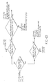
- Figure 4C is a flow chart of noise level analysis in finding the optimal contrast threshold and intensity threshold.
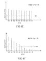
- Figure 4D is the first example of noise index distribution (R(GT,IT) ) with constant intensity threshold (IT) at 70 and multiple contrast thresholds (GT) varied from 60 to 15.
- Figure 4E is the second example of noise index distribution (R(GT,IT)) with constant intensity threshold (IT) at 70 and multiple contrast thresholds (GT) varied from 60 to 15.
- Figure 4F is the third example of noise index distribution (R(GT,IT) ) with constant intensity threshold (IT) at 70 and multiple contrast thresholds (GT) varied from 60 to 15.
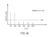
- Figure 4G is an example of noise index distribution (R(GT,IT)) with constant intensity threshold (IT) at 60 and multiple contrast thresholds (GT) varied from 70 to 220.
- Figure 4H is an example of noise index distribution (R(GT,IT) ) with constant intensity threshold (IT) at 60 and multiple contrast thresholds (GT) varied from 70 to 220.
- Figure 1 depicts the block diagram of a digital image processing system which automatically inspects the image quality of every thresholded image. For a poor thresholded image obtained from the image quality inspection, an image quality correction process is then initiated to search for optimal threshold parameters in order to obtain a legible and clean binary image. The image processing system comprises the following steps: (1) a paper document is digitally captured in gray scale which typically contain 8 bits per pixel; (2) the capture gray scale image (G) is fed through an adaptive image thresholding module to convert the gray scale image into a binary image (B); (3) the binary image is run through an image quality inspection and an image noise index (INI) is generated from the inspection; (4) the INI value determines the level of image quality, and the image quality is classified as poor when the INI value is greater than a predetermined threshold (ITH); (5) for a low quality image, an image quality correction is applied to the gray scale image in order to produce a legible, clean binary image. The detail of each image processing module is described in the following:
- The multi-windowing technique for thresholding an image using local image properties as described in U.S. Patent No. 5,583,659, the disclosure of which is hereby incorporated by reference, is applied to convert a gray scale image into a binary image. The thresholding technique calculates the threshold value for every pixel in an image based on the local image properties surrounding the pixel. The threshold value is then applied to turn the gray value of a pixel into bi-level value (black or white). The block diagram of the thresholding technique is summarized in Figure 2. The operation of the technique requires a user to supply a contrast threshold value (CT) and an intensity threshold value (IT) as shown in Figure 2A. The image quality of a thresholded image is determined by the input of the two threshold values (CT and IT). A thresholded image (CT, IT) as shown in Figure 2A means that the image quality of a thresholded image is a function of (CT, IT). The image quality of a thresholded image is evaluated by two factors: text readability (no image information loss) and smoothness of the white background (noise free on image background). The CT value controls the sensitivity of detecting thin, light text and line arts, and the it value accounts for the threshold of a uniform gray region. Assume that the CT value is normalized to the values in the range of 0 and 100 and the it value is between 0 and 255 as shown in Figure 2B. The CT value is often chosen to be sensitive enough for extracting all image information such as light text, thin lines, ... etc., and the IT value is set to turn light gray uniform region into white background. The threshold values at (CT=60, IT=90) as shown in Figure 2B is considered as an appropriate setup to extract all image information details. However, the setup of the threshold values at (CT=60, IT=90) may result in too sensitive for some documents due to the roughness of document papers and results in generating unwanted speckle noises in background of the thresholded images. The following section describes the method of automatic image noise inspection.
- As mentioned above, the CT value supplied to the thresholding technique is always set to be sensitive enough to extract all image information details so that the text readability is no longer an issue to be concerned in image quality evaluation. The evaluation of image quality is simplified to the detection of background noises in the thresholded image.
- Figure 3 is the processing steps of detecting noise level for a thresholded image. A binary image dilation operation is applied to the binary image (B) and generates a new binary image (B1). Three noise features are measured from the dilated binary image (B1). The normalized noise area (R) is taken as the image noise index (INI) of the binary image (B). The detailed description of the processing steps as shown in Figure 3 is stated in the following.
- Assume that black pixel is marked with "1" and white pixel is marked with "0" in a binary image. The image dilation operation is to expand the region of black dots by a local neighborhood operation as shown in Figure 3A. The center pixel "o" at the output is set to "0" only when all neighboring pixel XI in a 3x3 window, where I=1, ...8, are matched with the 3x3 zero mask. Otherwise, the center pixel "o" at the output is marked with black pixel, "1". The dilation operation is required because in some documents the text is printed with dot-matrix. The dilation operation connects the adjacent small dots into line segments so that the noise dots and the dots belonging to dot-matrix characters becomes distinguishable. A graphical example is illustrated in Figure 3B and Figure 3C. Figure 3B displays a binary image before image dilation. The number and size of the black dots in the left-handed side of the image is identical to the one in the right-handed side. If the number (or the area) of the noise dots is taken as a feature to evaluate level of noise, the feature will fail to differentiate the image patterns in both sides. However, after image dilation is applied, the original dotted pattern is turned into two straight line segments in the left-handed side as shown in Figure 3C. The dispersed noise patterns in the right handed side of the image stays the same except the enlarged noise dots. Hence, the number of noise dots becomes a useful feature in extracting real noise dots in the evaluation of noise level in the dilated binary image.
- The randomly, distributed small dots which contain no image information in a binary image are defined as noise. The noise measurement requires counting the number and the area of the small dots in a binary image. Figure 3D depicts the processing steps of noise measurement on the dilated binary image. First, it applies to a contour tracing method (see reference in U.S. Patent No. 5,974,199, the disclosure of which is hereby incorporated by reference) to extract the outline of every object in the dilated binary image. The contour pixels are extracted either in a sequence of clockwise or counterclockwise. The contours extracted in the order of clockwise are the outer contour (or black object contours), and the contours extracted in the order of counterclockwise are the inner contours (or white object contours). A size threshold (Ts) is applied to reject the large contour components whose size is too large to be considered as noise dots. The numbers of the remaining small contours are counted for black noise dots (NB) and white noise dots (NW), respectively, and the total noise area (NA) for black noise dots is calculated. The normalized noise area (R) is the ratio of NA value over the document area (DA) and is taken as the image noise index (INI). The NB and NW values are used to differentiate the white background from the black background. When the NB is greater than the NW, it indicates that the image has a white background. A large NW value then indicates that the background is black. This occurs when there is a con-tone image or large dark gray area existed in the document. Figure 3E is an example of the calculation of noise features. There are 20 black noise dots counted. That is that NB equals to 20. The number of white noise dots (NW) is counted as 10. Assume that the average area of each noise is calculated as Na, then the total noise area (NA) is 20 times Na and the image noise index (INI) is equal to NA/DA.
- The image noise index (INI) is used to judge the noise level of a binary image. When the INI value is below a specified threshold (ITH), the image is considered as good binary image. That means the binary image is legible and the background is clean. When it is greater than the ITH, it is classified as a noise binary image. The document is required to rescan or the gray scale image is retrieved if available for automatic image quality correction.
- Figure 4 shows the block diagram of image processing for automatic image quality correction. A multiple adaptive image thresholding process is applied to produce (N+M) binary images by orderly change of the N different contrast and the M different intensity threshold parameters. The noise level of every binary image in the (N+M) thresholded image is calculated, respectively. The optimal threshold parameters is obtained from the (N+M) pair of threshold values by analyzing the correlation of the (N+M) noise levels and the (N+M) pairs of contrast and intensity thresholds.
- The basic processing steps of the multiple adaptive thresholding are the same as the one in Figure 2 except with the multiple input of threshold values (CT, IT). The input (CT, IT) values are changed with 5 units decrement of CT and 30 units increment of IT in order of (60,70), (55,70), (50,70), (45,70), (40,70), (35,70), (30,70), (25,70), (20,70), (15,70), (60,100), (60,130), (60,160), (60,190) and (60,220). The 15 pairs of threshold values are fed into the adaptive thresholding process sequentially and generate 15 different binary images. By applying the process of noise feature extraction to the 15 different images separately as shown in Figure 3, there are 15 noise values, R(CT,IT), calculated and listed in Figure 4B.
- The objective of correlation analysis of noise and (CT,IT) is to identify the threshold values (CT,IT) which will be used in the adaptive thresholding process in generating least background noises while retaining all image information in a thresholded image. Figure 4C is the block diagram of the data analysis of selecting the optimal threshold values. First, scanning through the set of noise values, R(CT(I),70), where I=1,...,10, if the condition (A): R(CT(I),70)>Rth for all CT(I), is met, where the Rth is a predefined noise threshold value (Rth) as shown in Figure 4D. This indicates that the noise levels of all thresholded images are high and unrelated to the change of contrast threshold. Hence, it requires the change of intensity threshold (IT) in search of the optimal intensity threshold. On the other hand, if the condition (A) fails, it requires the change of the contrast threshold (CT) in search of the optimal contrast threshold.
- In the search of optimal contrast threshold, if all of the noise values, R(CT(I),70), I=1, ..., 10, are smaller than the noise threshold (Rth) as shown in Figure 4D, it indicates that the starting threshold setting at (CT,IT) = (60,70) generates little background noises and the final threshold values (CTF,ITF) = (60,70) are taken as the optimal threshold values. Otherwise, by examining the array of R(CT(I), 70) data, if the condition (B) : R(CT(I), 70)>R(CT(I+1), 70), I-1,..., 9, is satisfied, the final threshold values (CTF,ITF) = (CT(I), 70) is selected at where the CT(I) meets the condition: R(CT(I), 70)<Rth and R(CT(I+1), 70)>Rth. As the example shown in Figure 4E, the CT(I) value is selected at 35 and the final threshold values (CTF,ITF) = (35, 70). If the test of the condition (B) fails, the final threshold values (CTF,ITF) = (CT(I), 70) is selected at where the CT(I) meets the condition: R(CT(I), 70)<R(CT(I-1), 70). As the example shown in Figure 4F, the CT(I) value is selected at 40 and the final threshold values (CTF,ITF) = (40, 70).
- In the search of optimal intensity threshold, if the condition (C): R(60,IT(J))>Rth for all IT(J),J=1,...,6, is met, it indicates that the noise levels of all thresholded images are high and unrelated to the change of intensity threshold as the example shown in Figure 4G. The final threshold values (CTF,ITF) is set at (60, 70) which is the starting setup. This implies that there is no optimal threshold values detected and the final threshold values are assigned with the starting setting, (CTF,ITF) = (60, 70). On the other hand, if the test of the condition ( C ) fails, the (CTF,ITF) = (60,IT(J)) is selected at where R(60, IT(J-1))>Rth and R(60, IT(J))<Rth. As the example shown in Figure 4H, the IT(J) value is selected at 130. This indicates the intensity threshold at IT(J-1) = 100 is close to the background intensity and it is incapable of thresholding the intensity levels of background pixels and results in generating large amount of background noises.
Claims (4)
- An imaging process for producing a clean, readable binary image of a scanned document comprising the steps of:a. digitally capturing a document as a gray scale image;b. performing an image adaptive thresholding process to convert the gray scale image into a binary image;c. inspecting the binary image to create an image noise index value indicative of the amount of undesirable image artifacts or image information loss;d. determining whether the image noise index is equal to or greater than a predetermined threshold value; ande. performing an image correction process to produce a readable, clean binary image when said image noise index value is determined to be equal to or smaller than said threshold value.
- An imaging process for producing a clean, readable binary image as set forth in claim 1, wherein the image correction process comprises digitally capturing the document as a new gray scale image followed by repeating steps b.) - e.) until the image noise index value falls below the predetermined threshold value.
- An imaging process for producing a clean, readable binary image as set forth in claim 1, further comprising the step of storing the gray scale image and the image correction process comprises retrieving the gray scale image from storage followed by repeating steps b.) - e.) until the image noise index value falls below the predetermined threshold value.
- An imaging process for producing a clean, readable binary image as set forth in claim 1, wherein the step of determining comprises comparing the image noise index for an image with a predetermined threshold value selected to generate the least background noise while retaining all the image information on the gray scale image wherein when the image noise index value is at or above the predetermined threshold value the gray scale image is determined to be a noisy binary image requiring correction
Applications Claiming Priority (2)
| Application Number | Priority Date | Filing Date | Title |
|---|---|---|---|
| US50206 | 2002-01-16 | ||
| US10/050,206 US6970606B2 (en) | 2002-01-16 | 2002-01-16 | Automatic image quality evaluation and correction technique for digitized and thresholded document images |
Publications (3)
| Publication Number | Publication Date |
|---|---|
| EP1330111A2 true EP1330111A2 (en) | 2003-07-23 |
| EP1330111A3 EP1330111A3 (en) | 2004-12-08 |
| EP1330111B1 EP1330111B1 (en) | 2006-10-04 |
Family
ID=21963943
Family Applications (1)
| Application Number | Title | Priority Date | Filing Date |
|---|---|---|---|
| EP03075022A Expired - Lifetime EP1330111B1 (en) | 2002-01-16 | 2003-01-06 | Automatic image quality evaluation and correction technique |
Country Status (4)
| Country | Link |
|---|---|
| US (1) | US6970606B2 (en) |
| EP (1) | EP1330111B1 (en) |
| JP (1) | JP2003219184A (en) |
| DE (1) | DE60308739T2 (en) |
Cited By (3)
| Publication number | Priority date | Publication date | Assignee | Title |
|---|---|---|---|---|
| CN103268591A (en) * | 2013-04-20 | 2013-08-28 | 江苏新瑞峰信息科技有限公司 | High-speed scanning automatic rectifying system |
| US9894218B2 (en) | 2014-01-28 | 2018-02-13 | S-Printing Solution Co., Ltd. | Apparatus and method for processing scan data in the event of ESD input |
| CN113240630A (en) * | 2021-04-16 | 2021-08-10 | 深圳市安思疆科技有限公司 | Speckle image quality evaluation method and device, terminal equipment and readable storage medium |
Families Citing this family (36)
| Publication number | Priority date | Publication date | Assignee | Title |
|---|---|---|---|---|
| US20040100426A1 (en) * | 2002-11-21 | 2004-05-27 | Madhukar Gaganam | Field emission display brightness uniformity compensation system and method |
| FR2851357B1 (en) * | 2003-02-19 | 2005-04-22 | Solystic | METHOD FOR THE OPTICAL RECOGNITION OF POSTAL SENDS USING MULTIPLE IMAGES |
| KR100573668B1 (en) * | 2004-01-19 | 2006-04-26 | 삼성전자주식회사 | Scan image correction device and method thereof |
| US7528989B2 (en) * | 2004-07-08 | 2009-05-05 | Fuji Xerox Co., Ltd | Image processing apparatus and image processing method |
| KR20060050729A (en) * | 2004-08-31 | 2006-05-19 | 엘지전자 주식회사 | Method and apparatus for processing document image captured by camera |
| KR20060050746A (en) * | 2004-08-31 | 2006-05-19 | 엘지전자 주식회사 | Method for processing document image captured by camera |
| US8391614B2 (en) * | 2006-01-25 | 2013-03-05 | Equivio Ltd. | Determining near duplicate “noisy” data objects |
| US7936484B2 (en) * | 2006-06-14 | 2011-05-03 | Ronald Gabriel Roncal | Internet-based synchronized imaging |
| US7689004B2 (en) * | 2006-09-12 | 2010-03-30 | Seiko Epson Corporation | Method and apparatus for evaluating the quality of document images |
| US20080084584A1 (en) * | 2006-10-04 | 2008-04-10 | Nokia Corporation | Emphasizing image portions in an image |
| US8331721B2 (en) * | 2007-06-20 | 2012-12-11 | Microsoft Corporation | Automatic image correction providing multiple user-selectable options |
| US8116585B2 (en) * | 2007-08-09 | 2012-02-14 | Xerox Corporation | Background noise detection on rendered documents |
| US8054501B2 (en) * | 2007-11-07 | 2011-11-08 | Final Print Assurance Inc. | System and method for analyzing print quality |
| US10043201B2 (en) | 2008-01-31 | 2018-08-07 | Bill.Com, Inc. | Enhanced invitation process for electronic billing and payment system |
| US8073284B2 (en) | 2008-04-03 | 2011-12-06 | Seiko Epson Corporation | Thresholding gray-scale images to produce bitonal images |
| TW201027407A (en) * | 2009-01-13 | 2010-07-16 | Quanta Comp Inc | Light compensation method |
| KR101058726B1 (en) * | 2009-11-11 | 2011-08-22 | 삼성전자주식회사 | Image correction device and method for removing lighting components |
| US8520920B2 (en) * | 2009-11-11 | 2013-08-27 | Siemens Corporation | System for dynamically improving medical image acquisition quality |
| US8819789B2 (en) | 2012-03-07 | 2014-08-26 | Bill.Com, Inc. | Method and system for using social networks to verify entity affiliations and identities |
| JP6275116B2 (en) | 2012-04-13 | 2018-02-07 | レッド.コム,エルエルシー | Video projector system |
| US9025086B2 (en) | 2012-04-13 | 2015-05-05 | Red.Com, Inc. | Video projector system |
| CN102663390B (en) * | 2012-04-28 | 2014-04-30 | 长春迪瑞医疗科技股份有限公司 | Flow-cytometry microscopic image binaryzation method |
| JP6533363B2 (en) * | 2012-12-14 | 2019-06-19 | テクトロニクス・インコーポレイテッドTektronix,Inc. | Artifact detection method and video artifact detector |
| US20150012442A1 (en) * | 2013-03-14 | 2015-01-08 | Bill.Com, Inc. | Enhanced system and method for scanning and processing of payment documentation |
| US10115137B2 (en) | 2013-03-14 | 2018-10-30 | Bill.Com, Inc. | System and method for enhanced access and control for connecting entities and effecting payments in a commercially oriented entity network |
| US10417674B2 (en) | 2013-03-14 | 2019-09-17 | Bill.Com, Llc | System and method for sharing transaction information by object tracking of inter-entity transactions and news streams |
| US10572921B2 (en) | 2013-07-03 | 2020-02-25 | Bill.Com, Llc | System and method for enhanced access and control for connecting entities and effecting payments in a commercially oriented entity network |
| CN103886579B (en) * | 2013-12-11 | 2017-02-08 | 西安交通大学 | Abrasive particle chain self-adaptive segmentation method orienting online ferrographic image automatic identification |
| CN104112134A (en) * | 2014-07-09 | 2014-10-22 | 宁波摩视光电科技有限公司 | Image binary segmentation method of bullet apparent defect detection system based on AOI |
| CN104318571A (en) * | 2014-10-29 | 2015-01-28 | 兰州理工大学 | Image saliency algorithm evaluation method based on background non-saliency |
| CN104574399A (en) * | 2015-01-06 | 2015-04-29 | 天津大学 | Image quality evaluation method based on multi-scale vision significance and gradient magnitude |
| CN104899893B (en) * | 2015-07-01 | 2019-03-19 | 电子科技大学 | The picture quality detection method of view-based access control model attention |
| CN105426912B (en) * | 2015-11-12 | 2018-08-10 | 河南师范大学 | A kind of blind separating method of displacement aliased image |
| CN105374047B (en) * | 2015-12-15 | 2018-04-17 | 西安电子科技大学 | SAR image change detection based on improved bilateral filtering with cluster |
| EP4330915A1 (en) * | 2021-05-31 | 2024-03-06 | Shanghai United Imaging Healthcare Co., Ltd. | Systems and methods for image correction |
| CN115423808B (en) * | 2022-11-04 | 2023-03-24 | 合肥的卢深视科技有限公司 | Quality detection method for speckle projector, electronic device, and storage medium |
Citations (5)
| Publication number | Priority date | Publication date | Assignee | Title |
|---|---|---|---|---|
| US4982294A (en) * | 1987-07-24 | 1991-01-01 | Eastman Kodak Company | Apparatus for enhancing and thresholding scanned microfilm images and methods for use therein |
| US5583659A (en) * | 1994-11-10 | 1996-12-10 | Eastman Kodak Company | Multi-windowing technique for thresholding an image using local image properties |
| DE19536170A1 (en) * | 1995-09-29 | 1997-04-03 | Ibm | Image thresholding for optical character recognition |
| US5915037A (en) * | 1994-03-31 | 1999-06-22 | Licentia Patent-Verwaltungs Gmbh | Method and device for the binarization of pixel data |
| US5974199A (en) * | 1997-03-31 | 1999-10-26 | Eastman Kodak Company | Method for scanning and detecting multiple photographs and removing edge artifacts |
Family Cites Families (5)
| Publication number | Priority date | Publication date | Assignee | Title |
|---|---|---|---|---|
| US5208871A (en) * | 1990-10-19 | 1993-05-04 | Xerox Corporation | Pixel quantization with adaptive error diffusion |
| US5185674A (en) * | 1992-04-03 | 1993-02-09 | Eastman Kodak Company | Binary resolution decimation method and apparatus |
| US5832140A (en) * | 1993-12-14 | 1998-11-03 | Staplevision Inc. | Automated quality assurance image processing system |
| US5778092A (en) * | 1996-12-20 | 1998-07-07 | Xerox Corporation | Method and apparatus for compressing color or gray scale documents |
| US6674900B1 (en) * | 2000-03-29 | 2004-01-06 | Matsushita Electric Industrial Co., Ltd. | Method for extracting titles from digital images |
-
2002
- 2002-01-16 US US10/050,206 patent/US6970606B2/en not_active Expired - Lifetime
-
2003
- 2003-01-06 DE DE60308739T patent/DE60308739T2/en not_active Expired - Lifetime
- 2003-01-06 EP EP03075022A patent/EP1330111B1/en not_active Expired - Lifetime
- 2003-01-16 JP JP2003008359A patent/JP2003219184A/en active Pending
Patent Citations (5)
| Publication number | Priority date | Publication date | Assignee | Title |
|---|---|---|---|---|
| US4982294A (en) * | 1987-07-24 | 1991-01-01 | Eastman Kodak Company | Apparatus for enhancing and thresholding scanned microfilm images and methods for use therein |
| US5915037A (en) * | 1994-03-31 | 1999-06-22 | Licentia Patent-Verwaltungs Gmbh | Method and device for the binarization of pixel data |
| US5583659A (en) * | 1994-11-10 | 1996-12-10 | Eastman Kodak Company | Multi-windowing technique for thresholding an image using local image properties |
| DE19536170A1 (en) * | 1995-09-29 | 1997-04-03 | Ibm | Image thresholding for optical character recognition |
| US5974199A (en) * | 1997-03-31 | 1999-10-26 | Eastman Kodak Company | Method for scanning and detecting multiple photographs and removing edge artifacts |
Cited By (3)
| Publication number | Priority date | Publication date | Assignee | Title |
|---|---|---|---|---|
| CN103268591A (en) * | 2013-04-20 | 2013-08-28 | 江苏新瑞峰信息科技有限公司 | High-speed scanning automatic rectifying system |
| US9894218B2 (en) | 2014-01-28 | 2018-02-13 | S-Printing Solution Co., Ltd. | Apparatus and method for processing scan data in the event of ESD input |
| CN113240630A (en) * | 2021-04-16 | 2021-08-10 | 深圳市安思疆科技有限公司 | Speckle image quality evaluation method and device, terminal equipment and readable storage medium |
Also Published As
| Publication number | Publication date |
|---|---|
| EP1330111A3 (en) | 2004-12-08 |
| DE60308739D1 (en) | 2006-11-16 |
| US6970606B2 (en) | 2005-11-29 |
| DE60308739T2 (en) | 2007-08-23 |
| US20030133623A1 (en) | 2003-07-17 |
| JP2003219184A (en) | 2003-07-31 |
| EP1330111B1 (en) | 2006-10-04 |
Similar Documents
| Publication | Publication Date | Title |
|---|---|---|
| US6970606B2 (en) | Automatic image quality evaluation and correction technique for digitized and thresholded document images | |
| US8139117B2 (en) | Image quality analysis with test pattern | |
| JP3768052B2 (en) | Color image processing method, color image processing apparatus, and recording medium therefor | |
| EP1269394B1 (en) | Improved method for image binarization | |
| US7684625B2 (en) | Image processing apparatus, image processing method, image processing program, printed matter inspection apparatus, printed matter inspection method and printed matter inspection program | |
| EP1014691B1 (en) | An image processing system for reducing vertically disposed patterns on images produced by scanning | |
| JPH0869534A (en) | Method and equipment for detection of image quality | |
| EP2014082A1 (en) | Generating a bitonal image from a scanned colour image | |
| CN106548107A (en) | Bar code positioner and bar code localization method and apparatus for reading of bar code and bar code read method | |
| US20040131242A1 (en) | Monitoring method | |
| JPH09511598A (en) | Method and apparatus for binarizing pixel data | |
| KR100467565B1 (en) | Local binarization method of the imaging system. | |
| JP2020188424A (en) | Image processing apparatus, image forming apparatus, and image area determination method | |
| JP2009124332A (en) | Image processor, image processing method and program | |
| KR100260923B1 (en) | Apparatus and method for local binarization on images | |
| US11750748B2 (en) | Image processing apparatus, method, and storage medium to evaluate printed material with decreased influence of specific characteristic of print medium determined from margin area of printed chart | |
| JP2006058155A (en) | Printing tester | |
| KR100537829B1 (en) | Method for segmenting Scan Image | |
| JP4741289B2 (en) | Image processing apparatus and image processing method | |
| JP2019113477A (en) | Defect inspection equipment and defect inspection method | |
| JP2003091760A (en) | Transmitted pattern detecting device | |
| JP4743103B2 (en) | Image processing apparatus, image processing method, and computer program | |
| JP4449480B2 (en) | Print image inspection method and inspection apparatus | |
| JP3216165B2 (en) | Image region identification device and image region identification method | |
| JPH06103399A (en) | Image processor |
Legal Events
| Date | Code | Title | Description |
|---|---|---|---|
| PUAI | Public reference made under article 153(3) epc to a published international application that has entered the european phase |
Free format text: ORIGINAL CODE: 0009012 |
|
| AK | Designated contracting states |
Designated state(s): AT BE BG CH CY CZ DE DK EE ES FI FR GB GR HU IE IT LI LU MC NL PT SE SI SK TR |
|
| AX | Request for extension of the european patent |
Extension state: AL LT LV MK RO |
|
| PUAL | Search report despatched |
Free format text: ORIGINAL CODE: 0009013 |
|
| AK | Designated contracting states |
Kind code of ref document: A3 Designated state(s): AT BE BG CH CY CZ DE DK EE ES FI FR GB GR HU IE IT LI LU MC NL PT SE SI SK TR |
|
| AX | Request for extension of the european patent |
Extension state: AL LT LV MK RO |
|
| 17P | Request for examination filed |
Effective date: 20050511 |
|
| AKX | Designation fees paid |
Designated state(s): DE FR GB |
|
| GRAP | Despatch of communication of intention to grant a patent |
Free format text: ORIGINAL CODE: EPIDOSNIGR1 |
|
| GRAS | Grant fee paid |
Free format text: ORIGINAL CODE: EPIDOSNIGR3 |
|
| GRAA | (expected) grant |
Free format text: ORIGINAL CODE: 0009210 |
|
| AK | Designated contracting states |
Kind code of ref document: B1 Designated state(s): DE FR GB |
|
| REG | Reference to a national code |
Ref country code: GB Ref legal event code: FG4D |
|
| REF | Corresponds to: |
Ref document number: 60308739 Country of ref document: DE Date of ref document: 20061116 Kind code of ref document: P |
|
| ET | Fr: translation filed | ||
| PLBE | No opposition filed within time limit |
Free format text: ORIGINAL CODE: 0009261 |
|
| STAA | Information on the status of an ep patent application or granted ep patent |
Free format text: STATUS: NO OPPOSITION FILED WITHIN TIME LIMIT |
|
| 26N | No opposition filed |
Effective date: 20070705 |
|
| REG | Reference to a national code |
Ref country code: DE Ref legal event code: R082 Ref document number: 60308739 Country of ref document: DE Representative=s name: WAGNER & GEYER PARTNERSCHAFT PATENT- UND RECHT, DE |
|
| REG | Reference to a national code |
Ref country code: DE Ref legal event code: R082 Ref document number: 60308739 Country of ref document: DE Representative=s name: WAGNER & GEYER PARTNERSCHAFT MBB PATENT- UND R, DE Effective date: 20141028 Ref country code: DE Ref legal event code: R081 Ref document number: 60308739 Country of ref document: DE Owner name: KODAK ALARIS INC., ROCHESTER, US Free format text: FORMER OWNER: EASTMAN KODAK CO., ROCHESTER, N.Y., US Effective date: 20141028 Ref country code: DE Ref legal event code: R082 Ref document number: 60308739 Country of ref document: DE Representative=s name: WAGNER & GEYER PARTNERSCHAFT PATENT- UND RECHT, DE Effective date: 20141028 |
|
| REG | Reference to a national code |
Ref country code: FR Ref legal event code: TP Owner name: KODAK ALARIS INC., US Effective date: 20141212 Ref country code: FR Ref legal event code: CD Owner name: KODAK ALARIS INC., US Effective date: 20141212 |
|
| REG | Reference to a national code |
Ref country code: GB Ref legal event code: 732E Free format text: REGISTERED BETWEEN 20150108 AND 20150114 |
|
| REG | Reference to a national code |
Ref country code: FR Ref legal event code: PLFP Year of fee payment: 14 |
|
| REG | Reference to a national code |
Ref country code: FR Ref legal event code: PLFP Year of fee payment: 15 |
|
| REG | Reference to a national code |
Ref country code: FR Ref legal event code: PLFP Year of fee payment: 16 |
|
| PGFP | Annual fee paid to national office [announced via postgrant information from national office to epo] |
Ref country code: GB Payment date: 20211228 Year of fee payment: 20 Ref country code: FR Payment date: 20211222 Year of fee payment: 20 |
|
| PGFP | Annual fee paid to national office [announced via postgrant information from national office to epo] |
Ref country code: DE Payment date: 20211216 Year of fee payment: 20 |
|
| REG | Reference to a national code |
Ref country code: DE Ref legal event code: R071 Ref document number: 60308739 Country of ref document: DE |
|
| REG | Reference to a national code |
Ref country code: GB Ref legal event code: PE20 Expiry date: 20230105 |
|
| PG25 | Lapsed in a contracting state [announced via postgrant information from national office to epo] |
Ref country code: GB Free format text: LAPSE BECAUSE OF EXPIRATION OF PROTECTION Effective date: 20230105 |