JP6275116B2 - Video projector system - Google Patents
Video projector system Download PDFInfo
- Publication number
- JP6275116B2 JP6275116B2 JP2015505914A JP2015505914A JP6275116B2 JP 6275116 B2 JP6275116 B2 JP 6275116B2 JP 2015505914 A JP2015505914 A JP 2015505914A JP 2015505914 A JP2015505914 A JP 2015505914A JP 6275116 B2 JP6275116 B2 JP 6275116B2
- Authority
- JP
- Japan
- Prior art keywords
- light
- video
- optical
- green
- light engine
- Prior art date
- Legal status (The legal status is an assumption and is not a legal conclusion. Google has not performed a legal analysis and makes no representation as to the accuracy of the status listed.)
- Expired - Fee Related
Links
Images


Classifications
-
- H—ELECTRICITY
- H04—ELECTRIC COMMUNICATION TECHNIQUE
- H04N—PICTORIAL COMMUNICATION, e.g. TELEVISION
- H04N9/00—Details of colour television systems
- H04N9/12—Picture reproducers
- H04N9/31—Projection devices for colour picture display, e.g. using electronic spatial light modulators [ESLM]
- H04N9/3141—Constructional details thereof
- H04N9/315—Modulator illumination systems
- H04N9/3164—Modulator illumination systems using multiple light sources
-
- G—PHYSICS
- G02—OPTICS
- G02B—OPTICAL ELEMENTS, SYSTEMS OR APPARATUS
- G02B26/00—Optical devices or arrangements for the control of light using movable or deformable optical elements
- G02B26/08—Optical devices or arrangements for the control of light using movable or deformable optical elements for controlling the direction of light
- G02B26/10—Scanning systems
- G02B26/12—Scanning systems using multifaceted mirrors
- G02B26/123—Multibeam scanners, e.g. using multiple light sources or beam splitters
-
- G—PHYSICS
- G02—OPTICS
- G02B—OPTICAL ELEMENTS, SYSTEMS OR APPARATUS
- G02B27/00—Optical systems or apparatus not provided for by any of the groups G02B1/00 - G02B26/00, G02B30/00
- G02B27/48—Laser speckle optics
-
- G—PHYSICS
- G02—OPTICS
- G02B—OPTICAL ELEMENTS, SYSTEMS OR APPARATUS
- G02B30/00—Optical systems or apparatus for producing three-dimensional [3D] effects, e.g. stereoscopic images
- G02B30/20—Optical systems or apparatus for producing three-dimensional [3D] effects, e.g. stereoscopic images by providing first and second parallax images to an observer's left and right eyes
- G02B30/22—Optical systems or apparatus for producing three-dimensional [3D] effects, e.g. stereoscopic images by providing first and second parallax images to an observer's left and right eyes of the stereoscopic type
- G02B30/25—Optical systems or apparatus for producing three-dimensional [3D] effects, e.g. stereoscopic images by providing first and second parallax images to an observer's left and right eyes of the stereoscopic type using polarisation techniques
-
- G—PHYSICS
- G02—OPTICS
- G02B—OPTICAL ELEMENTS, SYSTEMS OR APPARATUS
- G02B6/00—Light guides; Structural details of arrangements comprising light guides and other optical elements, e.g. couplings
- G02B6/0001—Light guides; Structural details of arrangements comprising light guides and other optical elements, e.g. couplings specially adapted for lighting devices or systems
- G02B6/0005—Light guides; Structural details of arrangements comprising light guides and other optical elements, e.g. couplings specially adapted for lighting devices or systems the light guides being of the fibre type
-
- G—PHYSICS
- G02—OPTICS
- G02B—OPTICAL ELEMENTS, SYSTEMS OR APPARATUS
- G02B6/00—Light guides; Structural details of arrangements comprising light guides and other optical elements, e.g. couplings
- G02B6/04—Light guides; Structural details of arrangements comprising light guides and other optical elements, e.g. couplings formed by bundles of fibres
- G02B6/06—Light guides; Structural details of arrangements comprising light guides and other optical elements, e.g. couplings formed by bundles of fibres the relative position of the fibres being the same at both ends, e.g. for transporting images
-
- G—PHYSICS
- G03—PHOTOGRAPHY; CINEMATOGRAPHY; ANALOGOUS TECHNIQUES USING WAVES OTHER THAN OPTICAL WAVES; ELECTROGRAPHY; HOLOGRAPHY
- G03B—APPARATUS OR ARRANGEMENTS FOR TAKING PHOTOGRAPHS OR FOR PROJECTING OR VIEWING THEM; APPARATUS OR ARRANGEMENTS EMPLOYING ANALOGOUS TECHNIQUES USING WAVES OTHER THAN OPTICAL WAVES; ACCESSORIES THEREFOR
- G03B21/00—Projectors or projection-type viewers; Accessories therefor
- G03B21/005—Projectors using an electronic spatial light modulator but not peculiar thereto
-
- G—PHYSICS
- G03—PHOTOGRAPHY; CINEMATOGRAPHY; ANALOGOUS TECHNIQUES USING WAVES OTHER THAN OPTICAL WAVES; ELECTROGRAPHY; HOLOGRAPHY
- G03B—APPARATUS OR ARRANGEMENTS FOR TAKING PHOTOGRAPHS OR FOR PROJECTING OR VIEWING THEM; APPARATUS OR ARRANGEMENTS EMPLOYING ANALOGOUS TECHNIQUES USING WAVES OTHER THAN OPTICAL WAVES; ACCESSORIES THEREFOR
- G03B21/00—Projectors or projection-type viewers; Accessories therefor
- G03B21/14—Details
- G03B21/20—Lamp housings
- G03B21/206—Control of light source other than position or intensity
-
- G—PHYSICS
- G03—PHOTOGRAPHY; CINEMATOGRAPHY; ANALOGOUS TECHNIQUES USING WAVES OTHER THAN OPTICAL WAVES; ELECTROGRAPHY; HOLOGRAPHY
- G03B—APPARATUS OR ARRANGEMENTS FOR TAKING PHOTOGRAPHS OR FOR PROJECTING OR VIEWING THEM; APPARATUS OR ARRANGEMENTS EMPLOYING ANALOGOUS TECHNIQUES USING WAVES OTHER THAN OPTICAL WAVES; ACCESSORIES THEREFOR
- G03B33/00—Colour photography, other than mere exposure or projection of a colour film
-
- H—ELECTRICITY
- H04—ELECTRIC COMMUNICATION TECHNIQUE
- H04N—PICTORIAL COMMUNICATION, e.g. TELEVISION
- H04N13/00—Stereoscopic video systems; Multi-view video systems; Details thereof
- H04N13/30—Image reproducers
- H04N13/324—Colour aspects
-
- H—ELECTRICITY
- H04—ELECTRIC COMMUNICATION TECHNIQUE
- H04N—PICTORIAL COMMUNICATION, e.g. TELEVISION
- H04N13/00—Stereoscopic video systems; Multi-view video systems; Details thereof
- H04N13/30—Image reproducers
- H04N13/363—Image reproducers using image projection screens
-
- H—ELECTRICITY
- H04—ELECTRIC COMMUNICATION TECHNIQUE
- H04N—PICTORIAL COMMUNICATION, e.g. TELEVISION
- H04N9/00—Details of colour television systems
- H04N9/12—Picture reproducers
- H04N9/31—Projection devices for colour picture display, e.g. using electronic spatial light modulators [ESLM]
- H04N9/3102—Projection devices for colour picture display, e.g. using electronic spatial light modulators [ESLM] using two-dimensional electronic spatial light modulators
- H04N9/3105—Projection devices for colour picture display, e.g. using electronic spatial light modulators [ESLM] using two-dimensional electronic spatial light modulators for displaying all colours simultaneously, e.g. by using two or more electronic spatial light modulators
- H04N9/3108—Projection devices for colour picture display, e.g. using electronic spatial light modulators [ESLM] using two-dimensional electronic spatial light modulators for displaying all colours simultaneously, e.g. by using two or more electronic spatial light modulators by using a single electronic spatial light modulator
-
- H—ELECTRICITY
- H04—ELECTRIC COMMUNICATION TECHNIQUE
- H04N—PICTORIAL COMMUNICATION, e.g. TELEVISION
- H04N9/00—Details of colour television systems
- H04N9/12—Picture reproducers
- H04N9/31—Projection devices for colour picture display, e.g. using electronic spatial light modulators [ESLM]
- H04N9/3102—Projection devices for colour picture display, e.g. using electronic spatial light modulators [ESLM] using two-dimensional electronic spatial light modulators
- H04N9/3111—Projection devices for colour picture display, e.g. using electronic spatial light modulators [ESLM] using two-dimensional electronic spatial light modulators for displaying the colours sequentially, e.g. by using sequentially activated light sources
- H04N9/3117—Projection devices for colour picture display, e.g. using electronic spatial light modulators [ESLM] using two-dimensional electronic spatial light modulators for displaying the colours sequentially, e.g. by using sequentially activated light sources by using a sequential colour filter producing two or more colours simultaneously, e.g. by creating scrolling colour bands
-
- H—ELECTRICITY
- H04—ELECTRIC COMMUNICATION TECHNIQUE
- H04N—PICTORIAL COMMUNICATION, e.g. TELEVISION
- H04N9/00—Details of colour television systems
- H04N9/12—Picture reproducers
- H04N9/31—Projection devices for colour picture display, e.g. using electronic spatial light modulators [ESLM]
- H04N9/3141—Constructional details thereof
- H04N9/3144—Cooling systems
-
- H—ELECTRICITY
- H04—ELECTRIC COMMUNICATION TECHNIQUE
- H04N—PICTORIAL COMMUNICATION, e.g. TELEVISION
- H04N9/00—Details of colour television systems
- H04N9/12—Picture reproducers
- H04N9/31—Projection devices for colour picture display, e.g. using electronic spatial light modulators [ESLM]
- H04N9/3141—Constructional details thereof
- H04N9/315—Modulator illumination systems
- H04N9/3155—Modulator illumination systems for controlling the light source
-
- H—ELECTRICITY
- H04—ELECTRIC COMMUNICATION TECHNIQUE
- H04N—PICTORIAL COMMUNICATION, e.g. TELEVISION
- H04N9/00—Details of colour television systems
- H04N9/12—Picture reproducers
- H04N9/31—Projection devices for colour picture display, e.g. using electronic spatial light modulators [ESLM]
- H04N9/3141—Constructional details thereof
- H04N9/315—Modulator illumination systems
- H04N9/3161—Modulator illumination systems using laser light sources
-
- H—ELECTRICITY
- H04—ELECTRIC COMMUNICATION TECHNIQUE
- H04N—PICTORIAL COMMUNICATION, e.g. TELEVISION
- H04N9/00—Details of colour television systems
- H04N9/12—Picture reproducers
- H04N9/31—Projection devices for colour picture display, e.g. using electronic spatial light modulators [ESLM]
- H04N9/3141—Constructional details thereof
- H04N9/315—Modulator illumination systems
- H04N9/3167—Modulator illumination systems for polarizing the light beam
-
- H—ELECTRICITY
- H04—ELECTRIC COMMUNICATION TECHNIQUE
- H04N—PICTORIAL COMMUNICATION, e.g. TELEVISION
- H04N9/00—Details of colour television systems
- H04N9/12—Picture reproducers
- H04N9/31—Projection devices for colour picture display, e.g. using electronic spatial light modulators [ESLM]
- H04N9/3179—Video signal processing therefor
- H04N9/3188—Scale or resolution adjustment
-
- H—ELECTRICITY
- H01—ELECTRIC ELEMENTS
- H01S—DEVICES USING THE PROCESS OF LIGHT AMPLIFICATION BY STIMULATED EMISSION OF RADIATION [LASER] TO AMPLIFY OR GENERATE LIGHT; DEVICES USING STIMULATED EMISSION OF ELECTROMAGNETIC RADIATION IN WAVE RANGES OTHER THAN OPTICAL
- H01S3/00—Lasers, i.e. devices using stimulated emission of electromagnetic radiation in the infrared, visible or ultraviolet wave range
- H01S3/005—Optical devices external to the laser cavity, specially adapted for lasers, e.g. for homogenisation of the beam or for manipulating laser pulses, e.g. pulse shaping
Landscapes
- Physics & Mathematics (AREA)
- Engineering & Computer Science (AREA)
- Multimedia (AREA)
- Signal Processing (AREA)
- General Physics & Mathematics (AREA)
- Optics & Photonics (AREA)
- Projection Apparatus (AREA)
- Mechanical Optical Scanning Systems (AREA)
- Transforming Electric Information Into Light Information (AREA)
- Liquid Crystal (AREA)
Description
本願は、米国特許法119条(e)の下で、2012年4月13日に出願された「Laser Video Projector System」と題する米国仮特許出願第61/624,167号、2012年10月30日に出願された「Laser Video Projector System」と題する米国特許仮出願第61/720,295号、2013年3月13日に出願された「Video Projector System」と題する米国特許仮出願第61/780,958号、および2013年4月5日に出願された「Video Projector System」と題する米国特許仮出願第61/809,268号の優先権の利益を主張するものである。ここに挙げた出願それぞれの内容全体を参照によって本願明細書に引用したものとする。 This application is filed under US Patent Act 119 (e), US Provisional Patent Application No. 61 / 624,167 entitled “Laser Video Projector System” filed April 13, 2012, October 30, 2012. US Provisional Patent Application No. 61 / 720,295 entitled “Laser Video Projector System” filed on the same day, US Provisional Patent Application No. 61/780 entitled “Video Projector System” filed on March 13, 2013 , 958, and US Provisional Patent Application No. 61 / 809,268, entitled “Video Projector System”, filed Apr. 5, 2013. The entire contents of each of the applications cited herein are hereby incorporated by reference.
本開示は、全般的には、モジュール式レーザビデオ投影システムのような投影システムに関する。 The present disclosure relates generally to projection systems such as modular laser video projection systems.
プロジェクタシステムは、スクリーンもしくは拡散表示面に映像もしくは画像を投影するのに使用される。プロジェクタシステムは、光源として、キセノンランプもしくは水銀ランプなどのランプ、発光ダイオード(LED)、またはレーザを使用することができる。投影システムの中には、入射光を変調して画像もしくは映像を生成することができるものがある。光の変調は、液晶表示(LCD)パネル、デジタルマイクロミラーデバイス(DMD)、もしくはエルコス(liquid crystal on silicon「LCoS」)パネルのような変調パネルを使用して行うことができる。プロジェクタシステムは、投影される映像もしくは画像の色、画質、輝度、コントラスト、および鮮明さを改善するように構成された光学部品、電気部品、および機械部品を含むことができる。 Projector systems are used to project video or images onto a screen or diffuse display surface. The projector system can use a lamp such as a xenon lamp or a mercury lamp, a light emitting diode (LED), or a laser as a light source. Some projection systems can modulate incident light to generate an image or video. The light modulation can be performed using a modulation panel such as a liquid crystal display (LCD) panel, a digital micromirror device (DMD), or a liquid crystal on silicon (LCoS) panel. The projector system can include optical, electrical, and mechanical components configured to improve the color, image quality, brightness, contrast, and sharpness of the projected video or image.
本開示のシステム、方法、および装置は、それぞれ革新的な側面を有し、本明細書に開示されている望ましい特性に必須である、または望ましい特性に関係するのは、これらの側面の1つだけではない。請求項の範囲を限定せずに、有利な特徴について概説する。 Each of the disclosed systems, methods, and apparatus has innovative aspects, and one of these aspects is essential to, or related to, the desired characteristics disclosed herein. not only. Advantageous features are outlined without limiting the scope of the claims.
本明細書に記載されているビデオプロジェクタシステムは、さまざまな機能を提供するための多くの有利な構成を有する。ビデオプロジェクタシステムは、表示スクリーン上に投影するための比較的鮮明で色鮮やかな映像および画像を生成するように操作可能なさまざまな波長を有する光を生成するように構成されたライトエンジンを含む。ビデオプロジェクタシステムは、表示スクリーン上に投影されるビデオ信号を生成するように構成されたビデオプロセッサを含む。ビデオプロジェクタシステムは、ライトエンジンから光を受光して、その光をビデオプロセッサからのビデオ信号に従って変調するように構成された光学エンジンを含む。 The video projector system described herein has many advantageous configurations for providing various functions. A video projector system includes a light engine configured to generate light having various wavelengths operable to generate relatively clear and colorful images and images for projection onto a display screen. The video projector system includes a video processor configured to generate a video signal that is projected onto a display screen. The video projector system includes an optical engine configured to receive light from a light engine and modulate the light according to a video signal from a video processor.
これらのシステムそれぞれは、1つのユニットに組み合わされてもよいし、または任意の部分的組み合わせが、それ自体別個のユニットである他のユニットと共に1つのユニットに結合されてもよい。例えば、レーザライトエンジンと光学エンジンを1つの筐体内で組み合わせて1つのユニットを形成することができ、ビデオ処理システムは、有線もしくは無線通信を介してビデオ信号をライト・光学エンジンに送信するのに使用することができる。このことにより、ビデオプロジェクタ(例えば、この場合、ライトエンジンと光学エンジンを組み合わせた形)を偏光しなくても、さまざまなビデオ入力を使用することができる。別の例として、ビデオプロセッサと光学エンジンを1つのユニットに組み合わせることができ、レーザライトエンジンは、設定可能な数のレーザライトエンジンモジュールを使用して光学エンジン・ビデオ処理ユニットからの光出力を調節することができるようなモジュラーシステムとすることができる。別の例として、全ての3つのシステムを1つのユニットに組み合わせて、完全な自己完結型のビデオプロジェクタシステムを形成することができる。いくつかの実施形態では、モジュールによって、もしくはレーザライトエンジン、光学エンジン、および/またはビデオプロセッサへの追加要素によって、追加のシステムおよび/または機能が提供される。 Each of these systems may be combined into one unit, or any subcombination may be combined into one unit with other units that are themselves separate units. For example, a laser light engine and an optical engine can be combined in one housing to form a unit, and a video processing system can transmit video signals to the light and optical engine via wired or wireless communication. Can be used. This allows a variety of video inputs to be used without polarizing a video projector (e.g., in this case, a combination of a light engine and an optical engine). As another example, a video processor and optical engine can be combined into one unit, and the laser light engine uses a configurable number of laser light engine modules to regulate the light output from the optical engine and video processing unit. It can be a modular system like that. As another example, all three systems can be combined into a single unit to form a complete self-contained video projector system. In some embodiments, additional systems and / or functions are provided by modules or by additional elements to the laser light engine, optical engine, and / or video processor.
いくつかの実施形態は、1つまたは複数のライトエンジンモジュールと、1つまたは複数のビデオ処理モジュールと、1つまたは複数の光学エンジンモジュールとを含むモジュール式ビデオプロジェクタシステムを提供する。ビデオプロジェクタシステムをモジュラー形態にすることにより、ライトエンジン、ビデオプロセッサ、および/または光学エンジンを動的に構成することができる。 Some embodiments provide a modular video projector system that includes one or more light engine modules, one or more video processing modules, and one or more optical engine modules. By making the video projector system modular, the light engine, video processor, and / or optical engine can be dynamically configured.
ライトエンジンモジュールは、光学エンジンモジュールに光を供給するように構成された複数のレーザダイオードもしくは他のレーザ光源を含むことができる。ライトエンジンモジュールは、光学エンジンモジュールに伝達するために光出力を合成するように構成されてもよい。いくつかの実施形態では、ライトエンジンモジュールは、それぞれのライトエンジンモジュール内部を適切な温度で維持するための冷却システムを含む。 The light engine module can include a plurality of laser diodes or other laser light sources configured to provide light to the optical engine module. The light engine module may be configured to combine the light output for transmission to the optical engine module. In some embodiments, the light engine modules include a cooling system for maintaining the interior of each light engine module at an appropriate temperature.
ビデオ処理モジュールは、記憶媒体からビデオデータもしくは画像データを読み取ってもよいし、あるいは、コンピュータ、ゲームコンソール、もしくは他のデジタルビデオプレイヤ(例えば、ブルーレイプレイヤ、DVDプレイヤなど)のような別のデータソースからのビデオデータもしくは画像データもしくはネットワーク経由で送信されたビデオデータもしくは画像データを受信することができる。ビデオ処理モジュールは、ビデオデータを光学エンジンモジュールに送信して、ライトエンジンモジュールから受光した光を変調することができる。 The video processing module may read video data or image data from a storage medium, or another data source such as a computer, game console, or other digital video player (eg, Blu-ray player, DVD player, etc.) Video data or image data received from the network, or video data or image data transmitted via a network can be received. The video processing module can transmit video data to the optical engine module to modulate the light received from the light engine module.
光学エンジンモジュールは、光ファイバ(例えば、マルチモード光ファイバ)によってライトエンジンモジュールもしくは別の光源から光を受光するように構成することができる。光学エンジンモジュールは、受光した光を積分して実質的に均一な強度を有するほぼ矩形領域の光を生成して、積分した光を光変調パネル(例えば、LCoSパネル、DMD、LCD、もしくは他の空間光変調器)上で走査することができる。いくつかの実施形態では、ライトエンジンモジュールからの光は色成分に分離される。光学エンジンモジュールは、光学部品を利用して、ライトエンジンモジュールからの色の光路を結合して、光を変調パネル上で走査することができる。変調パネルはビデオ処理モジュールから受信したビデオ信号に従って光を変調し、光学エンジンは光を出力してスクリーン上に集束する。光学エンジンモジュールは、光出力を増加させ、解像度を向上させ、および/または立体映像を表示することができるように、2つ以上の変調パネルを含むことができる。 The optical engine module can be configured to receive light from the light engine module or another light source via an optical fiber (eg, a multimode optical fiber). The optical engine module integrates the received light to produce a substantially rectangular area of light having a substantially uniform intensity, and the integrated light is converted into a light modulation panel (eg, LCoS panel, DMD, LCD, or other Can be scanned on a spatial light modulator. In some embodiments, the light from the light engine module is separated into color components. The optical engine module can utilize optical components to combine the color optical paths from the light engine module and scan the light on the modulation panel. The modulation panel modulates the light according to the video signal received from the video processing module, and the optical engine outputs the light and focuses it on the screen. The optical engine module can include two or more modulation panels so as to increase light output, improve resolution, and / or display stereoscopic images.
いくつかの実施形態は、光学エンジンモジュールに含まれる変調パネルの解像度を向上させるように構成された光学エンジンモジュールを提供する。光学エンジンモジュールは、例えば、変調パネルからの各画素のサイズを縮小して、その後、縮小画素を屈折させて、高速で連続的にさまざまな形で画素を移動させて、変調パネルの解像度より高い解像度を有する表示ビデオ出力を生成するためのマルチレンズアレイを含む副画素生成器を含むことができる。いくつかの実施形態では、変調パネルは、パネルの向きを変えてさまざまな形で画素を移動させる。高速で連続的に異なる位置で画素を表示することによって、高い解像度が得られる。例えば、240Hzの速さで各画素に対して4つの異なる位置で1920×1080画素を表示させることによって、有効フレームレート60Hzで3840×2160画素以上の有効解像度が得られる。いくつかの実施形態では、光学エンジンモジュールは、一方向に沿った解像度が効率的に2倍になるように互いにずらされた画素データを生成する2つの変調パネルを含む。 Some embodiments provide an optical engine module configured to improve the resolution of a modulation panel included in the optical engine module. The optical engine module, for example, reduces the size of each pixel from the modulation panel, then refracts the reduced pixel and moves the pixels in various ways at high speeds continuously, higher than the resolution of the modulation panel A sub-pixel generator can be included that includes a multi-lens array for generating a display video output having a resolution. In some embodiments, the modulation panel changes the orientation of the panel to move the pixels in various ways. High resolution can be obtained by displaying the pixels at different positions continuously at high speed. For example, by displaying 1920 × 1080 pixels at four different positions for each pixel at a speed of 240 Hz, an effective resolution of 3840 × 2160 pixels or more can be obtained at an effective frame rate of 60 Hz. In some embodiments, the optical engine module includes two modulation panels that generate pixel data that are offset from each other such that the resolution along one direction is effectively doubled.
ビデオプロジェクタシステムは、スペックルの出現、または少なくとも1つにはコヒーレント光の強め合う干渉および弱め合う干渉が原因で生じるさまざまな輝点およびダークスポットの出現を低減するように構成された複数の機能を含むことができる。例えば、ライトエンジンは、光源レーザのスペクトル帯域幅を広げることによって、わずかに異なる周波数を有する複数のレーザエミッタを備えることによって、および/またはRF変調信号をエミッタに注入して光の放射スペクトルを広げることによって、周波数ダイバーシティを向上させるように構成されてもよい。スペックルは、例えば、光学エンジンに対する光の光ファイバ結合、レーザ光源、光変調器、および1つまたは複数のマルチレンズアレイの物理的配向によって得られる角度ダイバーシティ、マルチモードファイバによる光の複数の内部反射および光学部品による時変位相シフトによって得られる位相角ダイバーシティ、およびレーザ光源の機械的回転による偏光ダイバーシティを含む他の手段によって低減することができる。いくつかの実施形態では、プロジェクタ内で実質的に全てのスペックルが低減される。いくつかの実施形態では、表示スクリーンのスペックルを低減するのに、これらのスペックル低減技術のうちの1つまたは複数の技術が採用される。 The video projector system is configured to reduce the appearance of various bright spots and dark spots caused by the appearance of speckles, or at least one of the constructive and destructive interference of coherent light Can be included. For example, a light engine broadens the emission spectrum of light by broadening the spectral bandwidth of the source laser, by providing multiple laser emitters with slightly different frequencies, and / or injecting an RF modulated signal into the emitter. Thus, it may be configured to improve frequency diversity. Speckle includes, for example, optical fiber coupling of light to an optical engine, laser light source, light modulator, and angular diversity obtained by physical orientation of one or more multi-lens arrays, multiple interiors of light by multi-mode fiber It can be reduced by other means including phase angle diversity obtained by reflection and time-varying phase shift by optical components, and polarization diversity by mechanical rotation of the laser light source. In some embodiments, substantially all speckle is reduced in the projector. In some embodiments, one or more of these speckle reduction techniques are employed to reduce display screen speckle.
いくつかの実施形態は、わずかな差のあるほぼ等しい中心波長を有する複数のレーザを組み合わせて波長ダイバーシティを導入することにより、光学エンジンに伝送するための単色出力を供給する仮想レーザ光源を形成するレーザライトエンジンを提供する。この構造は、望ましい色出力もしくは適切な色出力を生成するために繰り返されて、修正されてもよい。これらの複数のレーザは、形成された仮想レーザ光源が比較的高レベルの光を供給すると同時に、形成された画像内のスペックルを低減するように、配向されて組み合わせられてもよい。複数のレーザは、相対的な物理的配向により角度ダイバーシティおよび偏光ダイバーシティを導入するように構成されてもよい。複数のレーザは、注入されたRF変調信号により放射スペクトルを広げるように構成されてもよい。複数のレーザは、スペックルを低減するために互いにインコヒーレントになるように選択されてもよい。 Some embodiments form a virtual laser source that provides a monochromatic output for transmission to an optical engine by combining multiple lasers with approximately equal center wavelengths with slight differences to introduce wavelength diversity. Provide a laser light engine. This structure may be repeated and modified to produce the desired or appropriate color output. These multiple lasers may be oriented and combined so that the formed virtual laser source provides relatively high levels of light while reducing speckle in the formed image. The plurality of lasers may be configured to introduce angular diversity and polarization diversity by relative physical orientation. The plurality of lasers may be configured to broaden the emission spectrum by the injected RF modulation signal. The multiple lasers may be selected to be incoherent with each other to reduce speckle.
いくつかの実施形態は、少なくとも1つの光源を備えたライトエンジンモジュールと、ビデオ処理モジュールと、光学エンジンモジュールとを含むモジュール式ビデオプロジェクタシステムを提供する。ライトエンジンモジュール、ビデオ処理モジュール、および光学エンジンモジュールは、少なくとも1つの組立構造体内でケーブルによって直接もしくは間接的に互いに接続可能な別個のモジュールを備える。少なくとも1つの組立構造体内で、光学エンジンモジュールは、ビデオ処理モジュールによって生成されたビデオデータを受信し、ライトエンジンモジュールによって供給された光を受光し、ビデオ処理モジュールによって生成されたビデオデータに基づいてライトエンジンモジュールによって供給された光を変調して、変調光を投影するように構成される。 Some embodiments provide a modular video projector system that includes a light engine module with at least one light source, a video processing module, and an optical engine module. The light engine module, the video processing module, and the optical engine module comprise separate modules that can be connected to each other directly or indirectly by a cable within at least one assembly structure. Within the at least one assembly structure, the optical engine module receives video data generated by the video processing module, receives light supplied by the light engine module, and is based on the video data generated by the video processing module. It is configured to modulate the light supplied by the light engine module and project the modulated light.
いくつかの実施態様では、ライトエンジンモジュールはレーザ光を供給する。いくつかの実施態様では、光源は複数のレーザを備える。 In some implementations, the light engine module provides laser light. In some implementations, the light source comprises a plurality of lasers.
いくつかの実施態様では、モジュール式ビデオプロジェクタシステムはさらに、組立ビデオプロジェクタシステムにケーブルによって直接もしくは間接的に接続可能な第2のライトエンジンモジュールを含む。さらに別の態様では、第1のライトエンジンモジュールおよび第2のライトエンジンモジュールはレーザ光を供給する。 In some implementations, the modular video projector system further includes a second light engine module that can be directly or indirectly connected to the assembled video projector system by a cable. In yet another aspect, the first light engine module and the second light engine module supply laser light.
いくつかの実施態様では、光学エンジンモジュールはさらに、ビデオ処理モジュールによって供給されたビデオデータに基づいてライトエンジンモジュールから受光した光を変調し、受光画素のサイズを縮小し、有界出力画素範囲内の縮小画素を少なくとも2カ所の位置に移動させるように構成され、縮小画素は、ビデオデータのフレームレートの少なくとも2倍の速さで少なくとも2カ所の位置に移動される。 In some embodiments, the optical engine module further modulates light received from the light engine module based on video data provided by the video processing module, reducing the size of the light receiving pixels, and within a bounded output pixel range. The reduced pixels are moved to at least two positions, and the reduced pixels are moved to at least two positions at a speed at least twice the frame rate of the video data.
いくつかの実施態様では、ライトエンジンモジュールによって供給された光は、少なくとも3色を含み、光学エンジンは少なくとも1つの変調素子の表面上で3色それぞれに対して別個の帯域を走査するように構成される。別の態様では、帯域間に実質的に光のないギャップが存在する。さらに別の態様では、光学エンジンは、走査を実行する回転屈折素子を含む。 In some embodiments, the light provided by the light engine module includes at least three colors and the optical engine is configured to scan a separate band for each of the three colors on the surface of the at least one modulation element. Is done. In another aspect, there is a substantially light free gap between the bands. In yet another aspect, the optical engine includes a rotational refractive element that performs the scan.
いくつかの実施形態は、複数の色の光を供給するように構成された複数のレーザを備えるライトエンジンモジュールを含むレーザプロジェクタシステムを提供する。レーザプロジェクタシステムは、光ファイバケーブル経由で複数の色の光を受光し、受光した光を少なくとも2つのLCoS変調パネルを使用して変調することにより投影出力ビデオを生成するように構成されたビデオ出力モジュールを含む。 Some embodiments provide a laser projector system that includes a light engine module comprising a plurality of lasers configured to provide a plurality of colors of light. A laser output system configured to receive a plurality of colors of light via a fiber optic cable and modulate the received light using at least two LCoS modulation panels to generate a projection output video Includes modules.
いくつかの実施形態は、入力ビデオ信号に対応する変調信号を生成するように構成されたビデオ処理システムを含むプロジェクタシステムを提供する。プロジェクタシステムは、変調信号を受信し、複数の光源からの光を変調して出力表示を生成するように構成されたプロジェクタ出力モジュールを含む。プロジェクタ出力モジュールは、入力ビデオ信号の少なくとも約2倍の有効解像度を有する出力表示を生成するように構成される。 Some embodiments provide a projector system that includes a video processing system configured to generate a modulated signal corresponding to an input video signal. The projector system includes a projector output module configured to receive a modulation signal and modulate light from a plurality of light sources to generate an output display. The projector output module is configured to produce an output display having an effective resolution of at least about twice the input video signal.
いくつかの実施形態は、ネイティブ解像度を有する入力ビデオ信号に対応する変調信号を生成するように構成されたビデオ処理システムを含むプロジェクタシステムを提供する。プロジェクタシステムは、変調信号を受信して、ネイティブ解像度の少なくとも約2倍の出力解像度を有する出力ビデオを生成するように構成されたプロジェクタ出力モジュールを含む。 Some embodiments provide a projector system that includes a video processing system configured to generate a modulated signal corresponding to an input video signal having native resolution. The projector system includes a projector output module configured to receive the modulated signal and generate an output video having an output resolution of at least about twice the native resolution.
いくつかの実施態様では、入力ビデオのフレームレートは約30Hzであり、出力ビデオのフレームレートは少なくとも約60Hzである。いくつかの実施態様では、ネイティブ解像度は少なくとも約1080本の垂直線であり、出力解像度は少なくとも約4320本の垂直線である。 In some implementations, the input video frame rate is about 30 Hz and the output video frame rate is at least about 60 Hz. In some embodiments, the native resolution is at least about 1080 vertical lines and the output resolution is at least about 4320 vertical lines.
いくつかの実施形態は、光を受光して、実質的に矩形の帯状に光を発散させる積分器を含むプロジェクタシステムを提供する。プロジェクタシステムは、画素配列を備え、光を変調して変調画素配列を生成するように構成された少なくとも1つの変調素子を含む。プロジェクタシステムは、複数の光学素子と可動屈折素子とを備える副画素生成器を含む。複数の光学素子は、変調画素配列を受信して、変調画素配列内の変調画素それぞれのサイズを縮小するように構成される。屈折素子は、縮小画素を移動させるように構成される。副画素生成器と変調素子とを組み合わせることにより、投影出力ビデオが生成される。 Some embodiments provide a projector system that includes an integrator that receives light and diverges the light into a substantially rectangular band. The projector system includes a pixel array and includes at least one modulation element configured to modulate light to generate a modulated pixel array. The projector system includes a sub-pixel generator that includes a plurality of optical elements and a movable refractive element. The plurality of optical elements are configured to receive the modulation pixel array and reduce the size of each of the modulation pixels in the modulation pixel array. The refractive element is configured to move the reduced pixel. By combining the sub-pixel generator and the modulation element, a projection output video is generated.
いくつかの実施態様では、投影出力ビデオの解像度は変調素子の解像度の少なくとも約2倍である。いくつかの実施態様では、投影出力ビデオの解像度は変調素子の解像度の少なくとも約4倍である。 In some embodiments, the resolution of the projection output video is at least about twice the resolution of the modulation element. In some embodiments, the resolution of the projection output video is at least about 4 times the resolution of the modulation element.
いくつかの実施形態は、光を受光して、第1の方向に沿った幅と幅より短い第2の方向の高さとを有する実質的に矩形の帯状に光を発散させる積分器を含むプロジェクタシステムを提供する。プロジェクタシステムは、矩形の帯の第2の方向に沿って積分器からの光を走査するように構成された走査システムを含む。プロジェクタシステムは、走査システムから光を受光して、受光した光を偏光するように構成された偏光システムを含む。プロジェクタシステムは、偏光された光を受光して、偏光された光を変調するように構成された少なくとも2つの変調素子であって、第1の変調素子は第1の偏光を示す光を変調し、第2の変調素子は第2の直交する偏光を示す光を変調する少なくとも2つの変調素子を含む。プロジェクタシステムは、第1の変調素子からの変調光と第2の変調素子からの変調光とを合成して立体ビデオ出力を生成するように構成された光学システムを含む。 Some embodiments include an integrator that receives light and diverges the light into a substantially rectangular strip having a width along a first direction and a height in a second direction that is less than the width. Provide a system. The projector system includes a scanning system configured to scan light from the integrator along a second direction of the rectangular band. The projector system includes a polarization system configured to receive light from the scanning system and polarize the received light. The projector system is at least two modulation elements configured to receive polarized light and modulate polarized light, wherein the first modulation element modulates light indicative of the first polarization. The second modulation element includes at least two modulation elements for modulating light exhibiting the second orthogonal polarization. The projector system includes an optical system configured to combine the modulated light from the first modulation element and the modulated light from the second modulation element to generate a stereoscopic video output.
いくつかの実施形態は、副画素生成器を使用してプロジェクタシステムの解像度を向上させる方法を提供する。該方法は、ソースビデオに従って変調された変調光を受光するステップを含む。該方法は、変調光をレンズアレイに向けるステップであって、各変調画素をレンズアレイのレンズに向けるステップを含む。該方法は、レンズを使用して受光画素のサイズを縮小するステップを含む。該方法は、屈折素子を使用して高速で連続的に有界出力画素範囲内の縮小画素を少なくとも2カ所の位置に移動させるステップを含む。縮小画素は、ソースビデオのフレームレートの少なくとも2倍の速さで少なくとも2カ所の位置に移動される。 Some embodiments provide a method of using a sub-pixel generator to improve the resolution of a projector system. The method includes receiving modulated light modulated according to a source video. The method includes directing modulated light to a lens array, directing each modulated pixel to a lens of the lens array. The method includes the step of reducing the size of the light receiving pixels using a lens. The method includes using a refractive element to move reduced pixels within a bounded output pixel range to at least two locations continuously at high speed. The reduced pixels are moved to at least two positions at a rate at least twice the frame rate of the source video.
いくつかの実施形態は、光源と、第1の解像度および第1のフレームレートを有するデジタルビデオデータを供給するように構成されたビデオ処理エンジンと、光路とを含むビデオプロジェクタシステムを提供する。光路は、ビデオ処理システムからデジタルビデオデータを受信し、光源により供給された光を受光し、変調素子を使用して受光した光を変調するように構成され、変調光は複数の画素を含む。光路はさらに、変調画素の個々の画素に対して、変調画素のサイズを縮小することにより変調副画素を生成して、変調副画素を少なくとも2カ所の異なる位置に移動させるように構成される。光路はさらに、少なくとも2カ所の位置のそれぞれにおいて出力ビデオとして変調副画素を投影するように構成される。 Some embodiments provide a video projector system that includes a light source, a video processing engine configured to provide digital video data having a first resolution and a first frame rate, and an optical path. The optical path is configured to receive digital video data from a video processing system, receive light supplied by a light source, and modulate the received light using a modulation element, the modulated light including a plurality of pixels. The optical path is further configured to generate a modulation subpixel for each individual pixel of the modulation pixel by reducing the size of the modulation pixel and move the modulation subpixel to at least two different positions. The optical path is further configured to project the modulated subpixel as output video at each of at least two positions.
いくつかの実施態様では、副画素は、変調画素のサイズによって規定される領域内で移動される。いくつかの実施態様では、副画素は、所定の幾何パターンに従って移動される。いくつかの実施態様では、少なくとも2カ所の位置は、少なくとも4つの異なる位置を含む。 In some implementations, the sub-pixel is moved within an area defined by the size of the modulation pixel. In some implementations, the subpixels are moved according to a predetermined geometric pattern. In some embodiments, the at least two locations include at least four different locations.
いくつかの実施態様では、光源はレーザ光を供給する。いくつかの実施態様では、光源は、複数の発光ダイオードによって生成された光を供給する。 In some embodiments, the light source provides laser light. In some embodiments, the light source provides light generated by a plurality of light emitting diodes.
いくつかの実施態様では、光路は、ライトエンジンモジュールから受光した光を変調するように構成された少なくとも1つの変調素子を含む。別の態様では、少なくとも1つの変調素子は、エルコス(liquid crystal on silicon「LCoS」)パネルを備える。さらに別の態様では、光路は、少なくとも2つの変調素子を含む。また別の態様では、2つの変調素子のうちの第1の変調素子からの投影光は、2つの変調素子のうちの第2の変調素子からの投影光から分数画素だけ空間的にずらされる。 In some embodiments, the optical path includes at least one modulation element configured to modulate light received from the light engine module. In another aspect, the at least one modulation element comprises a liquid crystal on silicon (“LCoS”) panel. In yet another aspect, the optical path includes at least two modulation elements. In another aspect, the projection light from the first modulation element of the two modulation elements is spatially shifted by a fractional pixel from the projection light from the second modulation element of the two modulation elements.
いくつかの実施態様では、光路は、変調画素を受信して変調副画素を生成するように構成されたマイクロレンズアレイを含む。いくつかの実施態様では、光路は、変調副画素を受信して変調副画素を移動させるように構成された可動屈折素子を含む。 In some implementations, the optical path includes a microlens array configured to receive modulation pixels and generate modulation subpixels. In some implementations, the optical path includes a movable refractive element configured to receive the modulation subpixel and move the modulation subpixel.
いくつかの実施態様では、出力ビデオの有効水平解像度は少なくとも約3840水平画素である。いくつかの実施態様では、出力ビデオの有効水平解像度は少なくとも約4000水平画素である。 In some implementations, the effective horizontal resolution of the output video is at least about 3840 horizontal pixels. In some implementations, the effective horizontal resolution of the output video is at least about 4000 horizontal pixels.
いくつかの実施態様では、投影変調副画素は、ライトエンジンモジュールから受光した光を変調するように構成された変調素子のネイティブ解像度の少なくとも約2倍の有効解像度を有する投影出力ビデオを生成する。さらに別の態様では、有効解像度は、変調素子のネイティブ解像度の少なくとも約4倍である。 In some implementations, the projection modulation sub-pixel produces a projection output video having an effective resolution that is at least about twice the native resolution of the modulation element configured to modulate light received from the light engine module. In yet another aspect, the effective resolution is at least about 4 times the native resolution of the modulation element.
いくつかの実施形態は、光源と、デジタルビデオデータを生成するように構成されたビデオ処理エンジンと、ビデオ処理システムからデジタルビデオデータを受信し、光源によって生成された光を受光するように構成された光路とを含むビデオプロジェクタシステムを提供する。光路は、受信したデジタルビデオデータに基づいて受光した光を変調するように構成された少なくとも2つの変調素子を含み、変調光は複数の画素を含む。光路はさらに、少なくとも2つの変調素子によって変調された光を屈折させて、表示面上に投影するために変調光を出力するように構成された光学系を含む。光路はさらに、少なくとも2つの変調素子のうちの第1の変調素子によって変調された投影光が少なくとも2つの変調素子のうちの第2の変調素子によって変調された投影光に対して空間的にずらされるように構成される。 Some embodiments are configured to receive a light source, a video processing engine configured to generate digital video data, receive digital video data from a video processing system, and receive light generated by the light source. A video projector system including an optical path is provided. The optical path includes at least two modulation elements configured to modulate the received light based on the received digital video data, and the modulated light includes a plurality of pixels. The optical path further includes an optical system configured to refract the light modulated by the at least two modulation elements and output the modulated light for projection onto the display surface. The optical path is further spatially offset with respect to the projection light modulated by the first modulation element of the at least two modulation elements with respect to the projection light modulated by the second modulation element of the at least two modulation elements. Configured to be.
いくつかの実施態様では、投影光は、個々の変調素子のネイティブ解像度の少なくとも 2倍の有効解像度を有する。 In some embodiments, the projection light has an effective resolution that is at least twice the native resolution of the individual modulator elements.
いくつかの実施形態は、少なくとも2色の光を供給する光源と、ソース解像度およびソースフレームレートを有するデジタルビデオデータを供給するように構成されたビデオ処理エンジンと、ビデオ処理エンジンからデジタルビデオデータを受信し、光源によって生成された光を受光するように構成された光路とを含むビデオプロジェクタを提供する。光路は、入射光を変調するように構成された変調素子を含む。光路は、特定の時点で各色が他の色のいずれとも異なる変調素子部分に入射するように、変調素子上で異なる色の光を走査する走査システムを含む。 Some embodiments provide a light source that provides at least two colors of light, a video processing engine configured to provide digital video data having a source resolution and a source frame rate, and digital video data from the video processing engine. A video projector is provided that includes a light path configured to receive and receive light generated by a light source. The optical path includes a modulation element configured to modulate incident light. The optical path includes a scanning system that scans light of a different color on the modulation element such that each color is incident on a different modulation element portion than any of the other colors at a particular point in time.
いくつかの実施態様では、光源は少なくとも3色の光を供給する。別の態様では、走査システムは、3色の光それぞれに対して別個の走査素子を備える1組の走査素子を含み、それぞれの走査素子は、変調素子に各色の光を向けるように移動するように構成される。走査素子は、互いに対して角度をずらして配置され、この角度のずれにより、特定の時点で各走査素子から発せられた光が他の走査素子から発せられた光とは異なる変調素子部分に照射される。さらに別の態様では、走査素子それぞれは回転素子を備え、回転素子の回転により、回転素子から発せられた光を変調素子上で走査することができる。別の態様では、回転素子は、六角形状屈折素子を備える。いくつかの実施態様では、走査システムは、特定の時点で、第1の色の光で変調素子の第1の帯域を照射し、第2の色の光で変調素子の第2の帯域を照射し、第3の色の光で変調素子の第3の帯域を照射する。さらに別の態様では、走査システムは、特定の時点で、照射帯域間の変調素子の一部を照射しない。 In some embodiments, the light source provides at least three colors of light. In another aspect, the scanning system includes a set of scanning elements with separate scanning elements for each of the three colors of light, each scanning element moving to direct the light of each color to the modulation element. Configured. The scanning elements are arranged at different angles with respect to each other, and due to this angular deviation, the light emitted from each scanning element at a specific time irradiates the modulation element portion different from the light emitted from the other scanning elements. Is done. In yet another aspect, each scanning element includes a rotating element, and the light emitted from the rotating element can be scanned on the modulating element by the rotation of the rotating element. In another aspect, the rotating element comprises a hexagonal refractive element. In some embodiments, the scanning system irradiates a first band of the modulator element with a first color of light and a second band of the modulator element with a second color of light at a particular time. Then, the third band of the modulation element is irradiated with the light of the third color. In yet another aspect, the scanning system does not illuminate a portion of the modulation element between the illumination bands at a particular time.
いくつかの実施態様では、走査システムは、変調素子の照射領域間に実質的に光のないギャップを形成するように構成される。 In some implementations, the scanning system is configured to form a substantially light-free gap between the illuminated areas of the modulation elements.
いくつかの実施態様では、光源は複数のレーザを備える。いくつかの実施態様では、光源は複数の発光ダイオードを備える。 In some implementations, the light source comprises a plurality of lasers. In some embodiments, the light source comprises a plurality of light emitting diodes.
いくつかの実施形態は、デジタルビデオデータを生成するように構成されたビデオ処理エンジンからデジタルビデオデータを受信し、少なくとも2色の光を供給する光源により生成された光を受光するように構成された光路を含むビデオプロジェクタを提供する。光路は、入射光を変調するように構成された変調素子と、特定の時点で各色が他の色のいずれとも異なる変調素子部分に入射するように変調素子上で少なくとも2色の異なる色の光を走査するように構成された走査システムを含む。 Some embodiments are configured to receive digital video data from a video processing engine configured to generate digital video data and receive light generated by a light source that provides at least two colors of light. A video projector including an optical path is provided. The optical path includes light of at least two different colors on the modulation element such that the modulation element is configured to modulate incident light and a modulation element portion where each color is different from any of the other colors at a particular time. A scanning system configured to scan.
いくつかの実施態様では、光源は少なくとも3色の光を供給する。別の態様では、走査システムは、3色の光それぞれに対して別個の走査素子を含む1組の走査素子を含み、それぞれの走査素子は各色の光を変調素子に向けるように移動するように構成される。走査素子は、互いに対して角度をずらして配置され、この角度のずれにより、特定の時点で各走査素子から発せられた光が他の走査素子から発せられた光とは異なる変調素子部分に当たるようになる。さらに別の態様では、走査素子それぞれは回転素子を備え、回転素子の回転により、回転素子から発せられた光を変調素子上で走査することができる。別の態様では、回転素子は、六角形状屈折素子を備える。さらに別の実施態様では、走査システムは、特定の時点で、第1の色の光で変調素子の第1の帯域を照射し、第2の色の光で変調素子の第2の帯域を照射し、第3の色の光で変調素子の第3の帯域を照射する。さらに別の態様では、走査システムは、特定の時点で、照射帯域間の変調素子の一部を照射しない。いくつかの実施態様では、走査システムは、変調素子上の照射領域間に実質的に光のないギャップを形成するように構成される。 In some embodiments, the light source provides at least three colors of light. In another aspect, the scanning system includes a set of scanning elements that include separate scanning elements for each of the three colors of light such that each scanning element moves to direct the light of each color toward the modulation element. Composed. The scanning elements are arranged at an angle with respect to each other so that the light emitted from each scanning element at a specific point in time hits a different modulation element part from the light emitted from the other scanning elements. become. In yet another aspect, each scanning element includes a rotating element, and the light emitted from the rotating element can be scanned on the modulating element by the rotation of the rotating element. In another aspect, the rotating element comprises a hexagonal refractive element. In yet another embodiment, the scanning system irradiates a first band of the modulator element with a first color of light and irradiates a second band of the modulator element with a second color of light at a particular time. Then, the third band of the modulation element is irradiated with the light of the third color. In yet another aspect, the scanning system does not illuminate a portion of the modulation element between the illumination bands at a particular time. In some implementations, the scanning system is configured to form a substantially light free gap between the illuminated regions on the modulation element.
いくつかの実施態様では、光源は複数のレーザを備える。いくつかの実施態様では、光源は複数の発光ダイオードを備える。 In some implementations, the light source comprises a plurality of lasers. In some embodiments, the light source comprises a plurality of light emitting diodes.
いくつかの実施態様では、ビデオプロジェクタは光源を含む。いくつかの実施態様では、ビデオプロジェクタはビデオ処理エンジンを含む。 In some implementations, the video projector includes a light source. In some implementations, the video projector includes a video processing engine.
いくつかの実施形態は、ビデオプロジェクタシステムにおいて光を変調する方法を提供する。該方法は、光源から少なくとも2色の光を受光するステップを含む。該方法は、ビデオ処理エンジンから、ソース解像度およびソースフレームレートを有するデジタルビデオデータを受信するステップを含む。該方法は、光源から受光した光を光路に沿って変調素子に向けるステップを含む。該方法は、受信したデジタルビデオデータに従って、変調素子に入射した光を変調するステップを含む。該方法は、特定の時点で各色が変調素子の異なる部分に入射するように、変調素子上で少なくとも2色の光を走査するステップを含む。 Some embodiments provide a method of modulating light in a video projector system. The method includes receiving at least two colors of light from a light source. The method includes receiving digital video data having a source resolution and a source frame rate from a video processing engine. The method includes directing light received from a light source along a light path to a modulation element. The method includes modulating light incident on a modulation element according to received digital video data. The method includes scanning at least two colors of light over the modulation element such that each color is incident on a different portion of the modulation element at a particular point in time.
いくつかの実施態様では、特定の時点で、変調素子に入射する各色間に実質的に光のないギャップが存在する。 In some implementations, at a particular point in time, there is a substantially light-free gap between each color incident on the modulation element.
いくつかの実施態様では、光を走査するステップは、回転屈折素子を使用して光を屈折させるステップを含む。別の態様では、回転屈折素子は六角形状屈折素子を含む。 In some implementations, scanning the light includes refracting the light using a rotational refractive element. In another aspect, the rotational refractive element includes a hexagonal refractive element.
いくつかの実施態様では、該方法は、各色それぞれの第1の偏光の光を光路に沿って導くステップと、各色それぞれの第2の直交偏光の光を第2の光路に沿って導くステップとを含む。別の態様では、該方法は、第2の変調素子を使用して第2の光路に沿って導かれた光を変調するステップを含み、第2の直交偏光を示す光は第2の変調素子に入射する。別の態様では、該方法は、特定の時点で各色が第2の変調素子の異なる部分に入射するように第2の変調素子上で第2の光路からの光を走査するステップを含む。別の態様では、該方法は、光路からの変調光と第2の光路からの変調光とを合成するステップと、合成された変調光を表示スクリーン上に投影するステップとを含む。別の態様では、合成された変調光は、表示スクリーン上で立体画像を形成する。 In some embodiments, the method includes directing light of a first polarization for each color along an optical path and directing light of a second orthogonal polarization for each color along a second optical path; including. In another aspect, the method includes modulating light guided along the second optical path using a second modulation element, wherein the light exhibiting the second orthogonal polarization is the second modulation element. Is incident on. In another aspect, the method includes scanning light from the second optical path on the second modulation element such that each color is incident on a different portion of the second modulation element at a particular time. In another aspect, the method includes combining the modulated light from the optical path and the modulated light from the second optical path, and projecting the combined modulated light onto a display screen. In another aspect, the combined modulated light forms a stereoscopic image on the display screen.
いくつかの実施形態は、少なくとも1つの光源を備えるライトエンジンモジュールと、ライトエンジンモジュールとは別個のパッケージに収容された光学エンジンモジュールとを含むモジュール式ビデオプロジェクタシステムを提供する。光学エンジンモジュールは、ビデオ処理機器によって生成されたビデオデータを受信し、ライトエンジンモジュールによって供給された光を受光し、ビデオ処理機器によって生成されたビデオデータに基づいてライトエンジンモジュールによって供給された光を変調して、変調光を投影するように構成される。 Some embodiments provide a modular video projector system including a light engine module comprising at least one light source and an optical engine module housed in a separate package from the light engine module. The optical engine module receives the video data generated by the video processing equipment, receives the light supplied by the light engine module, and receives the light supplied by the light engine module based on the video data generated by the video processing equipment. Is configured to project modulated light.
いくつかの実施態様では、ライトエンジンモジュールはレーザ光を供給する。別の態様では、光学エンジンモジュールとライトエンジンモジュールは、少なくとも1本の光ケーブルで接続される。 In some implementations, the light engine module provides laser light. In another aspect, the optical engine module and the light engine module are connected by at least one optical cable.
いくつかの実施態様では、モジュール式プロジェクタシステムはさらに、光学エンジンモジュールに接続される少なくとも第2のライトエンジンモジュールを含む。いくつかの実施態様では、光学エンジンモジュールは、同時に3個以下の別個のライトエンジンモジュールと共に動作するように構成される。いくつかの実施態様では、光学エンジンモジュールは、同時に4個以下の別個のライトエンジンモジュールと共に動作するように構成される。いくつかの実施態様では、光学エンジンモジュールは、同時に5個以下の別個のライトエンジンモジュールと共に動作するように構成される。いくつかの実施態様では、光学エンジンモジュールは、任意で、同時に1〜5個の別個のライトエンジンモジュールと共に動作するように構成される。 In some implementations, the modular projector system further includes at least a second light engine module connected to the optical engine module. In some implementations, the optical engine module is configured to operate with no more than three separate light engine modules simultaneously. In some implementations, the optical engine module is configured to operate with no more than four separate light engine modules simultaneously. In some implementations, the optical engine module is configured to operate with no more than five separate light engine modules simultaneously. In some implementations, the optical engine module is optionally configured to operate with 1 to 5 separate light engine modules simultaneously.
いくつかの実施態様では、光学エンジンモジュールはさらに、第2のライトエンジンモジュールによって供給された光を受光し、ビデオ処理機器によって生成されたビデオデータに基づいてライトエンジンモジュールによって供給された光を変調し、変調光を投影するように構成される。別の態様では、第1のライトエンジンモジュールおよび第2のライトエンジンモジュールはレーザ光を供給する。別の態様では、第1のライトエンジンモジュールと第2のライトエンジンモジュールは、少なくとも1本の光ケーブルで光学エンジンモジュールに接続される。いくつかの実施態様では、光源は複数のレーザを備える。 In some embodiments, the optical engine module further receives light provided by the second light engine module and modulates the light provided by the light engine module based on video data generated by the video processing equipment. And configured to project modulated light. In another aspect, the first light engine module and the second light engine module provide laser light. In another aspect, the first light engine module and the second light engine module are connected to the optical engine module by at least one optical cable. In some implementations, the light source comprises a plurality of lasers.
いくつかの実施態様では、光学エンジンモジュールはさらに、ビデオ処理機器によって生成されたビデオデータに基づいてライトエンジンモジュールから受光した光を変調し、受光画素のサイズを縮小して、有界出力画素範囲内の縮小画素を少なくとも2カ所の位置に移動させるように構成され、縮小画素は、ソースビデオのフレームレートの少なくとも2倍の速さで少なくとも2カ所の位置に移動される。別の態様では、縮小画素は、ソースビデオのフレームレートの少なくとも4倍の速さで少なくとも4カ所の位置に移動される。 In some implementations, the optical engine module further modulates light received from the light engine module based on video data generated by the video processing equipment to reduce the size of the light receiving pixels to provide a bounded output pixel range. The reduced pixels are moved to at least two positions, and the reduced pixels are moved to at least two positions at a rate at least twice the frame rate of the source video. In another aspect, the reduced pixels are moved to at least four locations at least four times the source video frame rate.
いくつかの実施態様では、ライトエンジンモジュールによって供給される光は少なくとも3色を含み、光学エンジンは少なくとも1つの変調素子の表面上で3色それぞれに対して別個の帯域を走査するように構成される。別の態様では、帯域間に実質的に光のないギャップが存在する。別の態様では、光学エンジンは、走査を実行する回転屈折素子を含む。 In some embodiments, the light provided by the light engine module includes at least three colors, and the optical engine is configured to scan a separate band for each of the three colors on the surface of the at least one modulation element. The In another aspect, there is a substantially light free gap between the bands. In another aspect, the optical engine includes a rotational refractive element that performs the scan.
いくつかの実施態様では、モジュール式ビデオプロジェクタシステムはさらに、ビデオ処理機器を含み、少なくとも光学エンジンモジュールとは別個のパッケージを有するビデオ処理モジュールを含む。別の態様では、ビデオ処理モジュールは、光学エンジンモジュールおよびライトエンジンモジュールとは別個のパッケージを有する。 In some implementations, the modular video projector system further includes a video processing module that includes video processing equipment and has a package that is separate from at least the optical engine module. In another aspect, the video processing module has a separate package from the optical engine module and the light engine module.
いくつかの実施形態は、複数の色の光を供給するように構成された複数のレーザを備えるライトエンジンモジュールと、光ファイバケーブル経由で複数の色の光を受光し、受光した光を少なくとも1つの変調素子を使用して変調し、投影出力ビデオを生成するように構成されたビデオ出力モジュールとを含むレーザプロジェクタシステムを提供する。例えば、少なくとも1つの変調素子はLCoS変調パネルとすることができる。 Some embodiments include a light engine module comprising a plurality of lasers configured to provide a plurality of colors of light, a plurality of colors of light via a fiber optic cable, and at least one received light. A laser projector system is provided that includes a video output module configured to modulate and generate projection output video using one modulation element. For example, the at least one modulation element can be an LCoS modulation panel.
いくつかの実施態様では、ビデオ出力モジュールは、受光した光を少なくとも2つの変調素子(例えば、LCoS変調パネル)を使用して変調することにより、投影出力ビデオを生成する。 In some implementations, the video output module generates projection output video by modulating the received light using at least two modulation elements (eg, LCoS modulation panels).
いくつかの実施形態は、入力ビデオ信号に対応する変調信号を生成するように構成されたビデオ処理システムを含むプロジェクタシステムを提供する。プロジェクタシステムは、変調信号を受信し、ネイティブ画素解像度を有する少なくとも1つの光変調素子を使用して投影出力ビデオを生成するように構成されたプロジェクタ出力モジュールを含む。出力ビデオは、光変調素子のネイティブ画素解像度の少なくとも約2倍の有効出力解像度を有する。 Some embodiments provide a projector system that includes a video processing system configured to generate a modulated signal corresponding to an input video signal. The projector system includes a projector output module configured to receive a modulation signal and generate projection output video using at least one light modulation element having native pixel resolution. The output video has an effective output resolution of at least about twice the native pixel resolution of the light modulation element.
いくつかの実施態様では、有効出力解像度はネイティブ画素解像度の少なくとも約4倍である。いくつかの実施態様では、入力ビデオ信号のフレームレートは約30Hzであり、出力ビデオのフレームレートは少なくとも約60Hzである。いくつかの実施態様では、ネイティブ画素解像度は少なくとも約1080本の垂直線であり、有効出力解像度は少なくとも約4320本の垂直線である。 In some embodiments, the effective output resolution is at least about 4 times the native pixel resolution. In some implementations, the frame rate of the input video signal is about 30 Hz and the frame rate of the output video is at least about 60 Hz. In some implementations, the native pixel resolution is at least about 1080 vertical lines and the effective output resolution is at least about 4320 vertical lines.
いくつかの実施形態は、ビデオ処理エンジンからデジタルビデオデータを受信し、光源から光を受光するように構成された光路を含むビデオプロジェクタシステムを提供する。光路は、変調素子を使用して、受信したデジタルビデオデータに従って、受光した光を変調するように構成され、変調光は複数の画素を含む。光路は、変調画素それぞれに対して、変調画素のサイズを縮小することによって変調副画素を生成し、変調画素のサイズによって規定された領域内で幾何パターンに従って副画素を移動させるように構成される。 Some embodiments provide a video projector system that includes an optical path configured to receive digital video data from a video processing engine and receive light from a light source. The optical path is configured to modulate the received light according to the received digital video data using a modulation element, the modulated light including a plurality of pixels. The optical path is configured to generate a modulated subpixel for each modulated pixel by reducing the size of the modulated pixel and move the subpixel according to a geometric pattern within an area defined by the size of the modulated pixel .
いくつかの実施態様では、幾何パターンは副画素周波数で繰り返される。別の態様では、副画素周波数はデジタルビデオデータのフレームレートより高い。 In some implementations, the geometric pattern is repeated at the subpixel frequency. In another aspect, the subpixel frequency is higher than the frame rate of the digital video data.
いくつかの実施態様では、光路は、変調画素のサイズを縮小するように構成された複数の光学素子を備える。別の態様では、複数の光学素子はマイクロレンズアレイを備える。 In some implementations, the optical path comprises a plurality of optical elements configured to reduce the size of the modulation pixel. In another aspect, the plurality of optical elements comprises a microlens array.
いくつかの実施態様では、光路は、幾何パターンに従って副画素を移動させるように構成された屈折素子を備える。 In some implementations, the optical path comprises a refractive element configured to move the subpixels according to a geometric pattern.
いくつかの実施態様では、光源はレーザ光を供給する。いくつかの実施態様では、光源は、複数の発光ダイオードによって生成された光を供給する。 In some embodiments, the light source provides laser light. In some embodiments, the light source provides light generated by a plurality of light emitting diodes.
いくつかの実施態様では、変調素子はLCoSパネルを備える。いくつかの実施態様では、光路は少なくとも2つの変調パネルを備える。別の態様では、2つの変調パネルのうちの第1の変調パネルからの投影光は、第2の変調パネルからの投影光とは異なる偏光を示す。 In some implementations, the modulation element comprises an LCoS panel. In some embodiments, the optical path comprises at least two modulation panels. In another aspect, the projection light from the first modulation panel of the two modulation panels exhibits a different polarization than the projection light from the second modulation panel.
いくつかの実施態様では、受信したデジタルビデオデータの水平解像度は少なくとも約3840水平画素である。 In some implementations, the received digital video data has a horizontal resolution of at least about 3840 horizontal pixels.
いくつかの実施態様では、投影変調副画素は、ライトエンジンモジュールから受光した光を変調するように構成された変調素子のネイティブ解像度の少なくとも約2倍の有効解像度を有する投影出力ビデオを生成する。別の態様では、有効解像度は、変調素子のネイティブ解像度の少なくとも約4倍である。 In some implementations, the projection modulation sub-pixel produces a projection output video having an effective resolution that is at least about twice the native resolution of the modulation element configured to modulate light received from the light engine module. In another aspect, the effective resolution is at least about 4 times the native resolution of the modulation element.
いくつかの実施形態は、ビデオ処理エンジンからデジタルビデオデータを受信し、光源から光を受光するように構成された光路を含むビデオプロジェクタシステムを提供する。光路は、受信したデジタルビデオデータに従って入射した受光光を変調するように構成された変調素子を含み、変調素子は複数の変調画素を生成するように構成された複数の画素を含む。光路は、複数の変調画素それぞれを幾何パターンに従って移動させるように構成された光学素子を備える副画素生成器を含む。 Some embodiments provide a video projector system that includes an optical path configured to receive digital video data from a video processing engine and receive light from a light source. The optical path includes a modulation element configured to modulate incident received light according to the received digital video data, the modulation element including a plurality of pixels configured to generate a plurality of modulation pixels. The optical path includes a sub-pixel generator comprising an optical element configured to move each of the plurality of modulation pixels according to a geometric pattern.
いくつかの実施態様では、副画素生成器の光学素子は可動屈折素子を備える。いくつかの実施態様では、副画素生成器はさらに、複数の変調画素それぞれのサイズを縮小するように構成された複数のレンズを備える。別の態様では、幾何パターンのサイズは変調画素のサイズによって規定される。いくつかの実施態様では、副画素生成器は、光学素子を移動させるように構成された機械要素をさらに備える。 In some embodiments, the optical element of the subpixel generator comprises a movable refractive element. In some implementations, the sub-pixel generator further comprises a plurality of lenses configured to reduce the size of each of the plurality of modulation pixels. In another aspect, the size of the geometric pattern is defined by the size of the modulation pixel. In some implementations, the sub-pixel generator further comprises a mechanical element configured to move the optical element.
いくつかの実施態様では、ビデオプロジェクタシステムはさらに光源を含む。別の態様では、光源は複数のレーザからの光を供給する。別の態様では、光源は複数のLEDからの光を供給する。 In some implementations, the video projector system further includes a light source. In another aspect, the light source provides light from multiple lasers. In another aspect, the light source provides light from a plurality of LEDs.
いくつかの実施態様では、ビデオプロジェクタシステムはさらに、光源からの光を変調素子上で走査するように構成された走査システムを含む。いくつかの実施態様では、ビデオプロジェクタシステムはさらに、変調画素を出力ビデオとして投影するように構成されたプロジェクタレンズを含む。 In some implementations, the video projector system further includes a scanning system configured to scan light from the light source over the modulation element. In some implementations, the video projector system further includes a projector lens configured to project the modulated pixels as output video.
いくつかの実施形態は、ビデオプロジェクタシステムを使用してビデオストリームを表示する方法を提供する。該方法は、ビデオ処理エンジンからデジタルビデオデータを受信するステップを含む。該方法は、光源から光を受光するステップを含む。該方法は、変調素子を使用して、受信したデジタルビデオデータに従って、受光した光を変調するステップを含み、変調光は複数の画素を含む。該方法は、変調画素それぞれに対して、変調画素のサイズを縮小することによって変調副画素を生成するステップと、変調副画素を変調画素のサイズによって規定された領域内で幾何パターンに従って移動させるステップとを含む。 Some embodiments provide a method for displaying a video stream using a video projector system. The method includes receiving digital video data from a video processing engine. The method includes receiving light from a light source. The method includes modulating received light according to received digital video data using a modulation element, the modulated light including a plurality of pixels. The method includes, for each modulation pixel, generating a modulation subpixel by reducing the size of the modulation pixel, and moving the modulation subpixel according to a geometric pattern within an area defined by the size of the modulation pixel. Including.
いくつかの実施態様では、変調画素のサイズを縮小するステップは、マイクロレンズアレイを使用して変調画素の画像を生成するステップを含み、変調画素のサイズの変調副画素のサイズに対する比の値は、少なくとも約2である。いくつかの実施態様では、該方法はさらに、出力ビデオとして変調副画素を投影するステップを含む。 In some embodiments, reducing the size of the modulation pixel includes generating an image of the modulation pixel using a microlens array, wherein the value of the ratio of the size of the modulation pixel to the size of the modulation subpixel is , At least about 2. In some implementations, the method further includes projecting the modulated subpixels as output video.
いくつかの実施態様では、副画素を移動させるステップは、変調副画素が幾何パターンに従って移動するように屈折素子を移動させるステップを含む。別の態様では、屈折素子を移動させるステップは、機械要素を使用して屈折素子の配向を調節するステップを含む。別の態様では、機械要素を移動させるステップは、屈折素子に結合されている複数のスピーカに電気信号を送信することにより、スピーカ内の電気音響素子が自身に結合されている屈折素子の一部を移動させるように作用するステップを含む。 In some implementations, moving the sub-pixel includes moving the refractive element such that the modulation sub-pixel moves according to the geometric pattern. In another aspect, moving the refractive element includes adjusting the orientation of the refractive element using a mechanical element. In another aspect, the step of moving the mechanical element includes transmitting the electrical signal to a plurality of speakers coupled to the refractive element so that the electroacoustic element in the speaker is part of the refractive element coupled to itself. Including the step of acting to move.
いくつかの実施態様では、幾何パターンはパターン周波数で繰り返される。別の態様では、パターン周波数はデジタルビデオデータのフレームレートより高い。 In some embodiments, the geometric pattern is repeated at the pattern frequency. In another aspect, the pattern frequency is higher than the frame rate of the digital video data.
いくつかの実施形態は、デジタルビデオデータから導出された信号に応答して、光源によって生成される光であって、少なくとも第1の色の第1の光および第2の色の第2の光に対応する入射光を変調するように構成された変調素子を含むビデオプロジェクタを提供する。ビデオプロジェクタは、光路内で変調素子の前に位置決めされるスキャナを含む。スキャナは、通過する第1の帯域の第1の光を変調素子の少なくとも一部に向けるように構成された第1の光学素子を含む。スキャナは、通過する第2の帯域の第2の光を変調素子の一部に向けるように構成された第2の光学素子を含み、第1の帯域および第2の帯域は、変調素子の一部に移った時にも実質的に別個の帯域として維持される。 Some embodiments provide light generated by a light source in response to a signal derived from digital video data, wherein the light is at least a first light of a first color and a second light of a second color. A video projector is provided that includes a modulation element configured to modulate incident light corresponding to. The video projector includes a scanner positioned in front of the modulation element in the optical path. The scanner includes a first optical element configured to direct first light of a first band passing therethrough to at least a portion of the modulation element. The scanner includes a second optical element configured to direct second light in a second band that passes through to a portion of the modulation element, the first band and the second band being one of the modulation elements. Even when moving to a section, it is maintained as a substantially separate band.
いくつかの実施態様では、第1の光学素子および第2の光学素子は、第1の帯域の光および第2の帯域の光を変調素子の一部に向けるように移動する。別の態様では、第1の光学素子は、実質的に第2の光学素子の形状と同様の幾何学的形状を有する。別の態様では、第1の光学素子および第2光学素子は、互いに対して回転方向にずらされ、第1の帯域の光および第2の帯域の光を変調素子の一部に向けるように同時に回転する。 In some implementations, the first optical element and the second optical element move to direct the first band of light and the second band of light to a portion of the modulation element. In another aspect, the first optical element has a geometric shape substantially similar to the shape of the second optical element. In another aspect, the first optical element and the second optical element are rotationally offset relative to each other and simultaneously direct the first band light and the second band light to a portion of the modulation element. Rotate.
図面は、本明細書に記載されている実施形態例を示すためのものであり、本開示の範囲を制限するものではない。全ての図面において、参照番号は参照要素同士がほぼ同じものであることを示すのに繰り返し使用されている場合もある。 The drawings are for purposes of illustrating example embodiments described herein and are not intended to limit the scope of the disclosure. In all of the drawings, reference numbers may be used repeatedly to indicate that reference elements are substantially the same.
特定の実施例および実施形態に関して、本開示の種々の態様について後述する。実施例および実施形態は、本開示を説明するためのものであって、本開示を限定するものではない。本開示内のいずれの内容も、開示されている実施形態の任意の特定の機能もしくは特徴が必須であることを意味するものではない。保護範囲は、本明細書の後に記載されている請求項によって定義され、本明細書内で説明されている任意の特定の実施形態によって定義されるのではない。 Various aspects of the disclosure are described below with reference to specific examples and embodiments. The examples and embodiments are intended to illustrate the present disclosure and are not intended to limit the present disclosure. Nothing in the present disclosure is meant to imply that any particular function or feature of the disclosed embodiments is essential. The protection scope is defined by the claims that follow this specification, and is not defined by any particular embodiment that is described within this specification.
以下の説明は、プロジェクタシステムからのカラー映像およびカラー画像の表示に関する。カラー画像の作成を可能にする赤色、緑色、および青色の光について述べる。所望の映像および画像を作成するのに他の色および他の色の組み合わせを使用することも可能である。本開示はこれらの他の色の組み合わせにも適用可能であり、本開示は特定の一部の色に限定されるものではないが、説明を簡単にするために、開示全体を通して赤色、緑色、および青色の色が使用されている。また、特定の実施形態はLCoSパネルを含む、もしくは使用するものとして記載されているが、他のタイプの光変調器も本明細書に記載されている実施形態に適合する。 The following description relates to the display of color video and color images from the projector system. The red, green, and blue light that enables the creation of color images is described. Other colors and combinations of colors can be used to create the desired video and images. The present disclosure is applicable to these other color combinations, and the present disclosure is not limited to certain specific colors, but for the sake of simplicity, red, green, And blue color is used. Also, although particular embodiments have been described as including or using LCoS panels, other types of light modulators are compatible with the embodiments described herein.
従来のプロジェクタシステムは、全ての構成部品を1つのボックス内に組み込んだものである。このようなシステムでは、一般的には、プロジェクタに光を供給するのにランプが使用される。一般的に、キセノンランプもしくは水銀ランプが使用される。これらのランプは、比較的多量の熱を発生させるので、費用のかかる、もしくは騒音を出す冷却システムを利用する場合がある。熱は光学部品もしくは電気部品を損傷する可能性がある。キセノンランプは赤外線を生成することが周知であるが、赤外線によりランプから放出される熱の量はさらに増加する。またキセノンランプは紫外線を生成することも周知であり、紫外線によりレンズ部品内の物質の有機物分解、例えば、染料の分解が生じる可能性がある。一般的に、このようなシステムにおいては、生成される光を効率的に集光して使用するために、ランプ光源をプロジェクタシステムの変調部品の近くに配置するのが望ましい。 The conventional projector system incorporates all the components in one box. In such systems, a lamp is typically used to supply light to the projector. Generally, a xenon lamp or a mercury lamp is used. Since these lamps generate a relatively large amount of heat, they may utilize expensive or noisy cooling systems. Heat can damage optical or electrical components. Although xenon lamps are well known to produce infrared radiation, the amount of heat released from the lamp by infrared radiation is further increased. It is also well known that xenon lamps generate ultraviolet rays, and the ultraviolet rays can cause decomposition of organic substances of substances in the lens component, for example, decomposition of dyes. Generally, in such a system, it is desirable to place the lamp light source close to the modulation component of the projector system in order to efficiently collect and use the generated light.
本明細書内に記載されている特定のプロジェクタは、レーザ光源もしくはLED光源を使用する。特定の実施形態によれば、光源は、例えば、光ファイバケーブルを使用して物理的および/または空間的にプロジェクタ内の光学部品から分離される。いくつかの実施形態では、狭い電磁波帯域の放射線を放つレーザもしくはLEDが選択されるので、有害な赤外線もしくは紫外線を生成する可能性はない。いくつかの実施形態では、広帯域光源が使用される場合もある。 Certain projectors described herein use laser light sources or LED light sources. According to certain embodiments, the light source is physically and / or spatially separated from the optical components in the projector using, for example, fiber optic cables. In some embodiments, a laser or LED that emits radiation in a narrow electromagnetic band is selected, so there is no possibility of generating harmful infrared or ultraviolet radiation. In some embodiments, a broadband light source may be used.
全ての構成部品が1つのユニットに組み込まれたプロジェクタシステムの中には、メンテナンスまたはアップグレードが難しいものがある。本明細書に示されているモジュール式システムでは、新技術が利用可能になった場合に、プロジェクタシステム内の他の構成部品の機能を損なわずに、モジュールを最新の状態にすることができる。例えば、プロジェクタシステムは、特定の時点では効率が悪い場合もあるが、経時的に見て、より効率的でコスト効率が良く強力であると言える緑色レーザダイオードのように、技術が向上した時にレーザモジュールを最新の状態にすることができる。さらに、モジュールは、新しい技術開発を利用するためにアップグレードもしくは再構築されてもよい。しかし、用途によっては、セットアップの容易さ、コンパクトさ、または他の要素から考えて、映像を投影するのに使用される全ての構成部品を組み込んだ1つのユニットにすることが有利であり、望ましい場合がある。 Some projector systems in which all components are incorporated into one unit are difficult to maintain or upgrade. The modular system shown herein allows the module to be up-to-date when new technology becomes available without compromising the function of other components in the projector system. For example, a projector system may be inefficient at a particular point in time, but as the technology improves, such as a green laser diode that can be said to be more efficient, cost effective and powerful over time, The module can be brought up to date. In addition, modules may be upgraded or rebuilt to take advantage of new technology developments. However, depending on the application, it may be advantageous and desirable to have a single unit that incorporates all the components used to project the image, considering ease of setup, compactness, or other factors. There is a case.
典型的なプロジェクタシステムでは、光出力を増加させるためにプロジェクタシステムに複数のランプが追加されることにより、プロジェクタ内の熱を増加させる。このような解決策は、より多くの損傷をもたらす可能性があり、プロジェクタを冷却するのにより多くの電力が消費される可能性がある。本明細書に示されているモジュール式レーザプロジェクタシステムは、複数の光源を積み重ねて、例えば、プロジェクタシステムの他の要素内の熱を増加させずに、変調素子への光入力を増加させるように構成される。 In a typical projector system, multiple lamps are added to the projector system to increase the light output, thereby increasing the heat in the projector. Such a solution can result in more damage and can consume more power to cool the projector. The modular laser projector system shown herein stacks multiple light sources to increase the light input to the modulation element without increasing heat in other elements of the projector system, for example. Composed.
いくつかの実施形態では、レーザプロジェクタシステムは、LCoSパネル、DMD、もしくはLCDパネルなどの変調器を照射するためにコヒーレント光源を使用することができる。コヒーレント光源を使用すると、光学的に粗い表面に光が投影された時にスペックルが生じる可能性がある。スペックルは、投影像内の目に見えるアーチファクトであり、さまざまな強度の光もしくは「サンドペーパーのような」光の輝点として現れる。スペックルは、強め合うようにまた弱め合うように干渉する可能性のある光のコヒーレント波面がスクリーン上にさまざまな明るい点や暗い点を発生させることで、引き起こされる可能性がある。スペックルは、画像の解像度や鮮明さを低下させる1つの原因と言える。したがって、レーザのような高コヒーレント光源を組み込んで、投影像内のスペックルの出現を低減したプロジェクタシステムを提供するのが有利である場合がある。
モジュール式プロジェクタシステムの概要
In some embodiments, the laser projector system can use a coherent light source to illuminate a modulator such as an LCoS panel, DMD, or LCD panel. Using a coherent light source can cause speckle when light is projected onto an optically rough surface. Speckle is a visible artifact in the projected image that appears as a bright spot of light of various intensities or “sandpaper-like” light. Speckle can be caused by coherent wavefronts of light that can interfere in both constructive and destructive ways, producing various bright and dark spots on the screen. Speckle can be said to be one cause for reducing the resolution and clarity of an image. Accordingly, it may be advantageous to provide a projector system that incorporates a highly coherent light source such as a laser to reduce the appearance of speckle in the projected image.
Overview of modular projector system
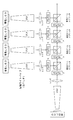
図1Aは、いくつかの実施形態のモジュール式ビデオプロジェクタシステム100のブロック図である。モジュール式ビデオプロジェクタシステム100は、スクリーン120に表示される映像を作成するために、光、ビデオ信号、および光変調を生成するのに使用されるさまざまなモジュールを含む。ビデオプロジェクタシステム100をモジュラー形式にすることにより、さまざまな利点が得られる。例えば、これらに限定されないが、修理が容易になる、構成部品もしくはモジュールのアップグレードが容易になる、プロジェクタの光出力が増加する、次世代の技術との前方互換性が得られる、表示される映像もしくは画像の画質が向上する、解像度が向上する、立体映像が得られる、さまざまなビデオフォーマットとの互換性が得られる、プロジェクタの部品間の冗長性が得られる、保護データ入力からの情報を復号する、複数の画面に1つのビデオソースからの情報を表示する、1つの画面に複数のビデオソースからの情報を表示する、スペックルを低減するなどの利点が得られる。
FIG. 1A is a block diagram of a modular
ビデオプロジェクタシステム100は、ビデオ信号を供給するように構成された1つまたは複数のビデオ処理モジュール105を含む。ビデオ処理モジュール105は、ケーブル107を使用して光学エンジンモジュール115に信号を送信するが、無線で通信することも可能である。ビデオ処理モジュール105は、1つまたは複数のビデオソースからの情報を変換して光学エンジンモジュール115にビデオ信号を送信し、光学エンジンモジュール115内の光変調素子を少なくとも部分的に作動させる。いくつかの実施形態では、ビデオ処理モジュール105は、光学エンジンモジュール115内で光を変調するエルコス(Liquid Crystal on Silicon「LCoS」)パネルへの入力を供給する。
ビデオ処理モジュール105は、(例えば、大容量記憶装置から、ネットワークソースから、および/または別の外部ビデオ処理システムからの)ビデオデータを処理もしくは受信して、光学エンジンモジュール115に対して適切な信号を出力するユニットとすることができる。いくつかの実施形態では、ビデオ処理モジュール105は、ビデオ処理機器を有する外部ソースからビデオ信号を受信するための入力部を含む。例えば、外部ソースは、REDRAY(商標)プレイヤ、コンピュータ、DVDプレイヤ、ブルーレイプレイヤ、ビデオゲーム機、スマートフォン、デジタルカメラ、ビデオカメラ、またはビデオ信号を供給することができる任意の他のソースとすることができる。ビデオデータは、例えば、HDMIケーブル、コンポーネントケーブル、コンポジットビデオケーブル、同軸ケーブル、イーサネットケーブル、光信号ケーブル、他のビデオケーブル、またはこれらの任意の組み合わせのような従来のケーブルを使用して、ビデオ処理モジュール105に送信される。いくつかの実施形態では、ビデオ処理モジュール105は、コンピュータ可読媒体上に記憶されているデジタル情報を読み取るように構成される。モジュール105は、例えば、ハードディスク、ソリッドステートドライブ(SSD)、光ディスク、フラッシュメモリ素子などのデータ記憶装置上の情報を読み取るように構成されてもよい。例えば、ビデオ処理モジュール105は、例えば、これらに限定されないが、非圧縮ビデオ、圧縮ビデオ(例えば、DVDで符号化されたビデオ、REDRAY(商標)符号化ビデオ、および/またはブルーレイディスクで符号化されたビデオ)などのデジタルビデオデータを読み取るように構成されてもよい。
外部ソース、光ディスク、もしくはデータ記憶装置は、ビデオ処理モジュール105にビデオデータを供給することができる。この場合、このビデオデータは、デジタルおよび/またはアナログ情報を含み、またビデオ規格に適合する情報を含み、および/または特定の解像度、例えば、HD(720p、1080i、1080p)、REDRAY(商標)、2K(例えば、16:9(2048×1152画素)、2:1(2048×1024画素)など)、4K(例えば、4096×2540画素、16:9(4096×2304画素)、2:1(4096×2048画素)など)、4K RGB、4K立体映像、4.5K水平解像度、3K(例えば、16:9(3072×1728画素)、2:1(3072×1536画素)など)、「5K」(例えば、5120×2700)、Quad HD(例えば、3840×2160画素)3D HD、3D 2K、SD(480i、480p、540p)、NTSC、PAL、または他の同様の規格もしくは解像度レベルのビデオデータを含む。本明細書内で使用される場合、xKの形式(例えば、上記の2Kや4K)で表現されている用語では、「x」の数は近似水平解像度を指す。したがって、「4K」解像度は、少なくとも約4000水平画素に相当し、「2K」は少なくとも約2000以上の水平画素に相当すると言える。モジュール式のビデオプロジェクタシステム100にすることより、ビデオプロセッサモジュール105をアップデートおよび/またはアップグレードして新たな機能もしくは異なる機能を提供することができるようになる。例えば、ビデオ処理モジュール105は、ビデオプロジェクタシステム100への許容入力フォーマットを変更するために変更または追加されてもよい。別の実施例では、保護データ入力からビデオ復号処理を行うためにビデオ処理モジュール105をアップデートすることができる。
An external source, optical disc, or data storage device can provide video data to the
モジュール式ビデオプロジェクタシステム100は、光学エンジンモジュール115に光を供給するように構成された1つまたは複数のライトエンジンモジュール110を含む。ライトエンジンモジュール110は、光ファイバケーブル112を使用して光学エンジンモジュール115を照射するように構成された1つまたは複数の光源を備えることができる。いくつかの実施形態では、ライトエンジンモジュール115は、主に電磁スペクトルの赤色領域、青色領域、および/または緑色領域内にある光を供給するように構成された光源(例えば、レーザ、LEDなど)を含む。いくつかの実施形態では、例えば、シアン、マゼンタ、黄色、白色、もしくは何か他の色の追加の色もしくは異なる色を供給することができる。
The modular
ライトエンジンモジュール110は、ダイレクト端面発光レーザダイオードもしくは垂直キャビティ面発光レーザダイオードなどのレーザダイオードを含むことができる。いくつかの実施形態では、ライトエンジンモジュール110内の光源(例えば、レーザダイオード)は、動作時に、約8W以下の電力、約10W以下の電力、約20W以下の電力、約25W以下の電力、約40W以下の電力、約60W以下の電力、約100W以下の電力、約8W〜約25Wの電力、約20W〜約30Wの電力、または約6W〜約40Wの電力を消費する。1つのライトエンジンモジュール110は、レーザダイオードから、複数の波長の光、一般に、赤色、緑色、および青色の光を供給することができる。光源によって消費される電力は一色当たりの電力としてもよいし(例えば、上記の範囲および限界値は光源ごとの範囲および限界値とすることができる)、または光源の組み合わせに対する電力としてもよい(例えば、ライトエンジン内部の全ての光源が上記の限界値および範囲内の電力を消費する)。光源によって消費される電力は、所望のサイズのスクリーンに応じて設定されてもよい。例えば、約12フィート以下の幅を有するスクリーンの場合、光源によって消費される電力は約6W〜約10W、または約8W以下とすることができる。少なくとも約12フィートおよび/または約100フィート未満の幅、あるいは少なくとも約30フィートおよび/または約90フィート未満の幅を有するスクリーンの場合、光源によって消費される電力は、約10W〜約100Wまたは約25W以下とすることができる。
The
ライトエンジンモジュール110は、ビデオプロジェクタシステム100の総照度および/または総光出力を増加させるために積み重ねられてもよい。図2は、より大型のスクリーン120に対応するために、ビデオプロジェクタシステム100に追加モジュールを追加した一例を示した図である。図2は、高さ2Hおよび長さ2Wのスクリーン120を示している。この例では、1つのライトエンジンモジュール110を有するビデオプロジェクタシステム100で、高さHおよび幅Wのスクリーンを十分に照射することができる。ビデオプロジェクタシステム100にさらに3つのライトエンジンモジュール110を追加して合計4つのライトエンジンモジュールにすることで、2H×2Wの寸法のスクリーン120を十分に照射する光を供給することができる。このモデルは、任意のスクリーンサイズまで拡張可能であるので、追加のライトエンジンモジュールを追加してスクリーン120を十分に照射できる光を生成することができる。このようにして、必要に応じて、出力される光のパワーを異なるスクリーンサイズに合わせて調整することができる。いくつかの実施形態では、ライトエンジンモジュール110内のそれぞれの光源は、少なくとも5フィート幅のスクリーンを十分に照射することができる。いくつかの実施形態では、それぞれの光源は、少なくとも15フィート幅のスクリーンを十分に照射することができる。
The
ライトエンジンモジュール110を追加することで、システム100によって消費される電力量が増加する。この場合、システム100によって消費される総電力消費量は、個々のモジュールそれぞれによって消費される消費電力量の合計である。例えば、1つのライトエンジンモジュール110は、約40Wの電力を消費することができる。同様の光源および冷却システムを有するライトエンジンモジュール110をさらに3つ追加することで、消費電力量が約120Wまで増加することになる。このように、ビデオプロジェクタシステム100の電力消費量は特定の用途に合わせて増減可能である。
Adding the
レーザ光源もしくはLED光源を有するライトエンジンモジュール110は、キセノン(Xe)ランプもしくは水銀(Hg)ランプのような光源と比較して利点を有する。例えば、レーザもしくはLEDは、モジュールの形で積み重ねられることで出力光の量を増加させ、その出力光は、例えば、1本または複数本の光ファイバケーブルを使用して、変調素子に少なくとも部分的に効率良く向けられる。別の利点は、レーザ光およびLED光は、一般的には、生成する熱のレベルは少ないので、追加のレーザもしくはLEDのライトエンジンモジュールを含むモジュール式プロジェクタ構造は、許容レベルの熱を維持することができ、熱によってプロジェクタの部品に加わる応力を低減する、または応力増加を防ぐことができる。さらに、モジュール式プロジェクタシステムは、費用のかかる、および/または騒音を出す冷却システムの必要性を低減する、または必要性をなくすことができる。
The
レーザ光源もしくはLED光源は、他の利点を有することができる。例えば、レーザ光源もしくはLED光源は、出力光の色をより適切に制御することができる。レーザ光源は、偏光光を供給することができ、LCoSパネルおよび他の光変調システムと併用されるのが有利である。 Laser light sources or LED light sources can have other advantages. For example, a laser light source or an LED light source can more appropriately control the color of output light. The laser light source can supply polarized light and is advantageously used in conjunction with LCoS panels and other light modulation systems.
いくつかの実施形態では、ライトエンジンモジュール110は、光源としてレーザを使用する。レーザは、本明細書に示されているように、多くの利点を有することができるが、投影像内のスペックル出現の一因にもなり得る。スペックル出現を低減するために、周波数ダイバーシティ、角度ダイバーシティ、位相角ダイバーシティ、および偏光ダイバーシティ効果を向上させる技術を使用することができる。これらの技術は全てレーザ光源のコヒーレンスを低減するのに寄与する。
In some embodiments, the
波長ダイバーシティは、ライトエンジンモジュール110で使用するレーザを選択することによって得られる。この場合、レーザは、比較的広いスペクトル帯域幅を有する。この点は、波長ダイバーシティが表示スクリーンに到達する光のコヒーレンス全体を低減するので、スペックルを低減するのに有利であると言える。いくつかの実施形態では、ダイレクト端面発光レーザダイオードは、約3〜5nmのスペクトル帯域幅を有する。この帯域域幅は、ダイオード励起固体(DPSS)レーザもしくはダイレクトダブルレーザ技術(0.5nm〜1nmと狭くなる可能性がある)と比較として比較的広い。利用可能な波長の製作範囲は、赤色、緑色、および青色のレーザそれぞれに対して約15nmの範囲で変化する可能性がある。いくつかの実施態様において、中心波長が約500nmの光を生成する光源では、中心波長の約10nmの広がりにより約90%のスペックルの低減が認められる。
Wavelength diversity is obtained by selecting the laser used in the
また、波長ダイバーシティは、異なる出力波長を有するが、知覚しにくい出力波長を有するレーザを使用して、プロジェクタシステム100内で達成することもできる。このことにより、プロジェクタ100内の1つの色に対して存在する異なる波長の数の平方根分の1だけスペックルを減らすことができる。これは、中心波長に数ナノメートルの広がりを有するレーザダイオードを使用してそれぞれのレーザエンジンモジュール110を構築することによって達成される。例えば、いくつかの青色レーザダイオードは、約458nm〜約468nmの範囲とすることで、青色領域の望ましい波長ダイバーシティを提供することができる。別の例では、緑色ダイオードは、約513nm〜約525nmの範囲とすることができる。
Wavelength diversity can also be achieved in
さらに、波長ダイバーシティは、1つまたは複数のレーザ光源に変調周波数を注入して、出力スペクトル帯域幅を広げることで達成することもできる。いくつかの実施形態では、レーザダイオードに数MHz〜数百MHzの変調周波数を注入することで、元の帯域幅の約2倍〜3倍スペクトル帯域幅が増加する。例えば、Green Nichiaテストダイオードは、約2nm〜約6nmのベーススペクトル帯域幅から増加された範囲の変調周波数が注入される。複数のレーザ光源は、異なる変調周波数を受信することができる、または同じ変調周波数であるが、他の光源に注入される変調周波数と位相がずれた変調周波数を受信することができる。このことにより、全体的により高い波長ダイバーシティ効果が得られる。 Furthermore, wavelength diversity can also be achieved by injecting a modulation frequency into one or more laser sources to widen the output spectral bandwidth. In some embodiments, injecting a modulation frequency of several MHz to several hundred MHz into the laser diode increases the spectral bandwidth by about 2 to 3 times the original bandwidth. For example, a Green Nichia test diode is injected with a modulation frequency in the range increased from a base spectral bandwidth of about 2 nm to about 6 nm. Multiple laser light sources can receive different modulation frequencies, or can receive modulation frequencies that are the same modulation frequency but out of phase with the modulation frequencies injected into the other light sources. This provides a higher wavelength diversity effect overall.
位相角ダイバーシティは、ライトエンジンモジュール110内の複数のエミッタソースを使用することにより導入することができる。複数の未校正光源および/または非コヒーレント光源を使用して複合高出力ライトエンジンを形成することによって、位相角ダイバーシティを導入してスペックルコントラストを低減することができる。スペックルは、無相関のレーザダイオードの数の平方根分の1だけ低減される。一例として、10W RGBモジュールは、およそ4個の青色レーザダイオード、6個の赤色ダイオード、そして50個の緑色ダイオードを使用することができ(この場合、緑色の光は、一般に、スペックルアーチファクトを発生させる最も大きな要因である可能性がある)、複数の光源のコヒーレンスを低減することでスペックルの出現を低減することができる。
Phase angle diversity can be introduced by using multiple emitter sources in the
角度ダイバーシティは、パターン配置された1つの光源に対して複数のエミッタを使用することで、プロジェクタシステム100内で達成することができる。例えば、エミッタ間が約4mm〜約50mm離間された放射パターンでレーザを配置することができる。それぞれのエミッタがコリメートされ、その後、光ファイバケーブルに集束された時にそれぞれのエミッタによって範囲が定まる立体角は、光ファイバケーブルに入ると無相関の多様な波面を形成する。角度ダイバーシティにより、最終投映画像のスペックルを低減することができる。
Angular diversity can be achieved in the
偏光ダイバーシティの形成は、レーザプロジェクタシステム100内のスペックルを低減する別の方法である。レーザ光源は偏光光を放出することができ、その偏光光は、光ファイバケーブルを通過した後でも大部分が均一に偏光された状態を維持することができる。それぞれのライトエンジンモジュール110に対して複数のエミッタを使用し、複数のエミッタを偏光角ダイバーシティ形成パターンで配置することで、スペックルを低減することができる。このことにより、以下に詳述するように、ビデオプロジェクタシステム100の光路全体にわたって偏光をランダム化することができ、水平偏光光および垂直偏光光の両方を使用するシステム100に有用である。
The formation of polarization diversity is another way to reduce speckle in the
ライトエンジンモジュール110のいくつかの実施形態は、多数の小型レーザを使用することで形成される仮想レーザ光源を備えることにより、複数のスペックルを低減する方法を使用することができる。例えば、互いにインコヒーレントな光を生成する約100個の個々のエミッタを使用することができる。約2nmの広いスペクトル帯域幅を有するエミッタが選択される。エミッタのスペクトル帯域幅は、エミッタにRF変調信号を注入することによって増加させることができ、約3nmおよび/または約5nmより広いスペクトル帯にまで増加させることができる。エミッタは、最大で約50mmの間隔で離間され、その間隔がマルチモードファイバに向かって次第に小さくなるように、角度ダイバーシティを形成するパターンで配置される。偏光ダイバーシティは、生成される光が他のエミッタと比較してさまざまな偏光角を有するようにエミッタを互いに対して機械的に回転させることによって形成される。さまざまな波長を有するが、知覚しにくい波長を有するエミッタを使用することができる。したがって、いくつかの実施形態は、波長ダイバーシティ、偏光ダイバーシティ、角度ダイバーシティ、および/または位相角ダイバーシティを利用して、スペックルを低減する仮想レーザ光源を提供する。
Some embodiments of the
1つまたは複数のライトエンジンモジュール110は、光学エンジンモジュール(単数または複数)115に接続されるように構成されたモジュール式スレッドに組み込まれてもよい。モジュール式スレッドは、積分器、ミラー、レンズ、および光学エンジンモジュール115に注入される前の光出力を成形もしくは調整するための他の光学素子を含むことができる。モジュール式スレッドは、光源からの光を光学エンジンモジュール115に搬送するように構成された光ファイバケーブルを含むことができる。光ファイバケーブルは、1本または複数本のマルチモード光ファイバを備え、光を搬送するのに2本以上の光ファイバケーブルが使用される。いくつかの実施形態では、光源内の異なる色ごとに1つのマルチモード光ファイバを備える。いくつかの実施形態では、入力光の異なる色ごとに複数の光ファイバを備える。例えば、いくつかのプロジェクタシステム100では、ライトエンジンモジュール110内の光の各色が、光をプロジェクタに輸送するために1本の400umマルチモードファイバを有することができ、400umマルチモードファイバはRGBモジュールでは合計3本になる。別の実施例として、高出力プロジェクタシステム100では、ライトエンジンモジュール110内の各色が最大で5本のマルチモードファイバを有することができ、マルチモードファイバは高出力RGBモジュールでは最大で合計15本になる。接続部の出力端部におけるマルチモードファイバの間隔が、角度ダイバーシティによるスペックル低減に寄与することができる。
The one or more
上述したように、ライトエンジンモジュール110からの光は、光ファイバケーブル112もしくは他の適切なケーブル112を使用して光学エンジンモジュール115内の変調素子に向けられる。この機能により、光源が光学エンジンから物理的および空間的に離間されることになる。このことにより、プロジェクタヘッド(例えば、光学エンジンモジュール115)は1つの空間に存在し、光源(例えば、ライトエンジンモジュール110)は別の空間に存在することができるので、光源に接続された冷却システムから生じたノイズが映像表示に干渉する可能性がある場合に有利であると言える。いくつかの実施形態では、光ファイバケーブルもしくは他のケーブルの長さは、約10フィート以上および/または約100フィート以下、約1m以上および/または約100m以下、もしくは約3m以上および/または約50m以下とすることができる。種々の実施形態では、ケーブルは、約1m〜約100m、または約1m〜約10mの長さである。
As described above, light from the
マルチモード光ファイバを使用することで、プロジェクタシステム100内に存在するスペックル全体を低減するように構成することができる。マルチモードファイバは、光がケーブルの端から端まで進む時にさまざまな光路をランダム化する働きをする。ケーブル内の光の複数の内部反射により出力光が生成される。この場合、光同士の位相角差はランダム化されている。位相角をランダム化することで光のコヒーレンスが低減されるので、スペックルが低減される。さらに、マルチモードファイバは、偏光をランダム化して、スペックルの出現を低減する偏光ダイバーシティを導入することができる。
By using the multi-mode optical fiber, the entire speckle existing in the
ビデオプロジェクタシステム100は、ビデオ処理モジュール105から受信した信号に従ってライトエンジンモジュール110からの光を変調するように構成された1つまたは複数の光学エンジンモジュール115を含む。レーザプロジェクタシステム100のいくつかの実施形態は、複数のビデオ出力もしくは画像出力を生成するために複数の光学エンジンモジュール115を備える。例えば、2つの光学エンジンモジュール115を使用して、立体映像を作成するために直交偏光した2つの対応するビデオストリームを作成することができる。別の実施例として、ビデオ処理モジュール105を使用して、2つ以上の光学エンジンモジュール115(それぞれの光学モジュール115は少なくとも1つのライトエンジンモジュール110を有する)を作動させて、スクリーン120上に同一のデータを表示することによって、スクリーン上の表示画像の輝度を上げることができる。例えば、屋外ディスプレイの場合、4つのプロジェクタヘッド(および関連するレーザモジュール)がスクリーン上に同一のデータを表示する。別の実施例として、複数の光学エンジンモジュール115を使用して、任意の個々の光学エンジンモジュール115よりも高解像度のビデオストリームを表示することができる。これは、ビデオ処理モジュール105が高解像度のビデオストリームを個々の光学エンジンモジュール115に適した複数のピースに分割することで達成される。その後、それぞれの光学エンジンモジュール115は、ビデオ処理モジュール105からビデオ信号の一部を受信して、その部分を規定の構成でスクリーン120上に表示することができる。さらに本明細書内に示されているように、ビデオプロジェクタシステム100のいくつかの実施形態は、個々の光変調素子によって得られる有効解像度よりも高い有効解像度を有するビデオストリームを作成することができる個々の光学エンジンモジュール115を備える。
本明細書内で図3に関してより詳細に説明するように、光学エンジンモジュール115は、1つまたは複数の光変調パネルを照射して、変調光をスクリーン120に向けるように構成された複数の要素を備えることができる。光学エンジンモジュール115は、積分器、レンズ、ミラー、プリズム、リレーレンズ、テレセントリックレンズ、プロジェクタレンズ、回転プリズム要素、偏光素子、色合成器、光変調パネル、マイクロレンズアレイ、可動屈折素子、または任意のこれらの組み合わせもしくは他の適切な光学部品を含むことができる。
As described in more detail herein with respect to FIG. 3, the
ケーブル107および112は、モジュール式システムへの第三者の接続を制限する専用コネクタを含む特殊ケーブルとすることができる。ケーブルおよびコネクタによる第三者のアクセスを制限することにより、プロジェクタシステム100がプロジェクタシステム100内の部品を損傷させる恐れのある互換性のない機器と接続されないようにすることができる。いくつかの実施形態では、プロジェクタシステム100へのコンポーネントアクセスは、PINもしくは他の識別または認証手段による認証が必要な暗号化接続を使用することで制限される。ケーブルおよびコネクタ107、112を使用して、統合ビデオプロジェクタシステム100を形成するように複数のモジュールを相互接続することによって、モジュール式ビデオプロジェクタシステム100を形成することができる。
図1Bは、ビデオ処理モジュール105と、複数のライトエンジンモジュール110と、光学エンジンモジュールもしくはプロジェクタヘッド115とを備えるモジュール式ビデオプロジェクタシステム100の実施形態例を示した図である。ビデオ処理モジュール105およびライトエンジンモジュール110は、モジュールを収容する構造であるラック125内に取り付けられた状態で示されている。光学エンジンモジュール115は、ラック125の上に設置された状態で示されているが、ケーブル107、112が届く範囲内であればどこに配置されてもよく、モジュール105、110を収容したラック125から別の空間に配置されてもよい。ビデオ処理モジュール105およびライトエンジンモジュール110は、このようなラック125に取り付けることができるように構成されるので、有利には、セットアップおよび設定が容易なシステムを提供することができる。またこのシステムは、分解、輸送、および再組立が容易であると言える。
FIG. 1B is a diagram illustrating an example embodiment of a modular
ビデオ処理モジュール105は、1つまたは複数のケーブル107を使用して光学エンジンモジュール115にビデオ信号を供給するように構成されてよい。ビデオ信号は、光学モジュール115のみが信号を復号することができるように暗号化されてもよい。
ライトエンジンモジュール110はそれぞれ、赤色、緑色、および青色の光を光学エンジン115に供給することができる。それぞれのライトエンジンモジュール110からの赤色の光は、ライトエンジンモジュール110内のそれぞれの赤色光源用の光ファイバを有する光ファイバ束を含むケーブルを使用して伝送される。例えば、ビデオプロジェクタシステム100は、赤色光源を1つずつ含む5個のライトエンジンモジュール110を備える。ケーブル112は、5個のライトエンジンモジュール110それぞれからの赤色の光を伝送する5本の光ファイバを備えた赤色の光用の光ファイバ束を含み、光ファイバは、ライトエンジンモジュール115内の赤色光源1つに対して1本である。ライトエンジンモジュール115からの青色の光および緑色の光は、同様の手段によって光学エンジンモジュール115に伝送することができる。本明細書内でより詳細に示されるように、光ファイバからの光を光学エンジンモジュール115内でまとめて合成することができる。図示されているように、ビデオプロジェクタシステム100は、5個のライトエンジンモジュール110を含む。例えば、1つ、2つ、3つ、4つ、もしくは6つ以上の他の数のライトエンジンモジュールを使用してもよい。
Each of the
図1Bに示されているように、ビデオプロジェクタシステム100は、光を生成するモジュール、ビデオ信号を生成するモジュール、および供給された光を変調するモジュールの別個のモジュールを含む。いくつかの実施形態では、これらの1つまたは複数のモジュールを1つのユニットもしくは1つのモジュールにまとめることができる。例えば、ライトエンジンは、ビデオプロジェクタシステム100内で光学エンジンと組み合わされてもよい。この実施形態では、光源は光を生成することができ、生成された光は、その後、同じ筐体もしくは構造体の内部で変調パネルによって変調される。光は、上述したように、光ファイバケーブルを使用して、またはレンズ、プリズム、および/またはミラーのような光学部品を使用して光源から伝送される。別の実施例として、ビデオプロセッサ、ライトエンジン、および光学エンジンを組み合わせて単一統合ビデオプロジェクタシステム100を形成してもよい。モジュールを1つまたは複数のユニットにまとめることで、特定のケーブルもしくは通信要素を省くことができるが、機能性および全体構造はほとんど変わらない。例えば、ビデオプロセッサと光学エンジンとの間のケーブルおよび/またはライトエンジンと光学エンジンとの間のケーブルは、これらのモジュールがビデオプロジェクタシステム100内にまとめて含まれる場合には省かれてもよい、もしくは変更されてもよい。
光学エンジンモジュール例
As shown in FIG. 1B, the
Example of optical engine module
図3は、いくつかの実施形態のビデオプロジェクタシステム100用の光学エンジン115のブロック図である。例えば、図3に示されている光学エンジン115は、モジュール式プロジェクタシステムに適合し、および/または図1および図2に関して本明細書に示されているような光学エンジンモジュール115とすることができる。上述したように、光学エンジンモジュール115は、ライトエンジン110から光を受光し、ビデオプロセッサ105からビデオ信号を受信し、受信したビデオ信号を使用して受光した光を変調し、得られた映像または画像をスクリーン120上に投影する。光学エンジン115は、入射光を変調して画像もしくは映像を投影するという目的を達成するのに適したさまざまな要素を使用することができる。光学エンジン115の一実施形態例は、本明細書では、上述の形で構成された上述の要素を有する形で説明されているが、これは単に一実施形態例に過ぎず、異なる形で構成された異なる要素を有する他の実施形態も以下の開示内容の範囲内とする。
FIG. 3 is a block diagram of an
光学エンジン115は、ライトエンジン110から光305を受光する。図示されているように、光は、可視電磁スペクトルの赤色、緑色、および青色の部分の範囲に含まれる3つの一般的な波長帯域内にあるように構成される。作成される画像および映像の所望の輝度、細部、および色を実現するために、他の色および組み合わせを使用することも可能である。光305は、シングルモードもしくはマルチモードファイバのような光ファイバを使用して、または他の手段を使用して、光学エンジン115に伝送することができる。本明細書で示されているように、マルチモードファイバを使用することにより、位相角ダイバーシティおよび角度ダイバーシティ効果によりスペックルを低減することができる。
積分器の例
The
Integrator example
受光した光305は、まず、積分器310に通される。積分器310は、光305を均一化するように構成される。また、積分器310は、光305の角度ダイバーシティを向上させてスペックルを低減することができる。いくつかの実施形態では、積分器310は、中空もしくは中実の内部反射型ライトパイプであり、複数の反射を利用して入射光を均一な矩形パターンの出射光に変換する。積分器310を使用して、変調パネルなどの表面上の光の均一性を向上させて、照明源のアスペクト比を変調パネルに効率的に適合させることができる。
The received light 305 is first passed through the
いくつかの実施形態では、積分器310は、水平分散均一化ロッドとレンチキュラーレンズアレイとを含む。レンチキュラーレンズアレイは、入射光を多数の角度に分散させることにより光源の角度ダイバーシティを向上させることができる。例えば、ホモジナイザの前後で2つのレンチキュラー拡散器を水平方向および垂直方向に使用して、広がった「扇型」状の出力光線を角度分割して、光を各変調素子上の平坦な領域に空間的に積分することができる。そうすることで、光学エンジンは、スペックルの出現を低減することができる。いくつかの実施形態では、積分器310は、均一化ロッドと回転もしくは振動位相シフトディスクとを含む。積分器310を通る光線に時変位相シフトを導入することで、光源の連続走査間で空間的かつ時間的コヒーレンスを効率的に平均化することによりスペックルが低減される。さらに、積分器310は、光源からの光を所定の領域にわたって均一に分散するように構成された他の光学素子を含んでもよい。例えば、積分器は、水平方向および垂直方向に光を分散するように設計されたミラー、レンズ、および/または屈折素子を含んでもよい。いくつかの実施形態は、入射光305の色ごとに別個の均一化光学系を備える。
スリット走査システムの例
In some embodiments,
Example of slit scanning system
積分器310を出た光は、その後、スピナー315に送られる。いくつかの実施形態では、積分器310からの光は、部分的もしくは完全にスピナー315内の回転素子に、もしくは回転素子内に集束される。図4は、ビデオプロジェクタシステム100内のスリット走査システム315の一例を示した図である。スピナーもしくはスリット走査システム315は、所定の速さで回転するように構成された多角形状屈折素子405を含む。光が回転素子405を通過すると、光は屈折されて、回転素子の回転により光がスピナー315を出る時の光の垂直方向もしくは水平方向の位置を変化させる。図4に示されているように、積分器310からの光線は、スピナー405の回転に従って初期位置から最終位置まで走査される。いくつかの実施形態は、本明細書内で図6に関してより詳細に説明されるように、積分器からの入射光の色ごとに回転素子405を備える。
The light exiting
いくつかのプロジェクタシステムでは、異なる色の光が変調パネル全体(もしくはほぼ全体)に連続して送られる。いくつかのスリット走査の実施形態では、六角形状スピナー405を使用して、空白もしくは黒色の周期または黒色と混合された赤色、緑色、および青色の光のスリットを変調パネル上で走査することができる。各スリットは、1つまたは複数の隣接列(例えば、1、2、3、5、10、100、180、200またはそれ以上の列)を含んでもよい。いくつかの実施形態では、スリットに含まれる列の数は画像の高さの何分の1であり、画像の高さの約1/3、画像の高さの約1/4、画像の高さの約1/6、画像の高さの約1/8、画像の高さの約1/12、またはその他の何分の1である。一例として、画像の高さは1080列であり、スリットは180列を含む。マーク対スペース比は、少なくとも1つには変調パネルのセトリングタイムに基づいて定義される。セトリングタイムは、連続フレームを走査することができる速度に関連している。スリット走査形態の利点として、有効フレームレートが3倍もしくは約3倍増加するということが挙げられる。それは、連続走査プロジェクタシステムが各色を一度表示するのに要する時間内に、赤色、緑色、および青色が3回ずつ表示されるためである。別の利点は、動きの速い画像の赤色、緑色、および青色の部分を知覚できるほどずれて表示する可能性がある連続走査プロジェクタシステムと比較した場合に、色収差を低減もしくは除去することができるという点である。
In some projector systems, light of different colors is sent continuously over the entire modulation panel (or nearly the whole). In some slit scanning embodiments, a
いくつかの実施形態では、スピナー405は、スペックルを低減するためにコーティングされる。スピナー405をコーティングすることで、光を拡散させることにより角度ダイバーシティを向上させることができる。また、ミラーのコーティングが、積分器310から受光した光の両端を広げることにより画像にアーチファクトが形成される場合がある。いくつかの実施形態では、図5に示されるように、マイクロレンズアレイ410がスピナー405の前に配置される。マイクロレンズアレイ410は、光を分散させて広範囲の角度にわたって光を広げることにより、角度ダイバーシティを向上させることができるので、スペックルを低減することができる。いくつかの実施形態では、マイクロレンズアレイ410は、スピナー405の回転軸に平行になるように配向されたレンチキュラーレンズである。いくつかの実施形態では、マイクロレンズアレイは、プロジェクタの光路内で、スピナー405の前ではなく後に配置される、またはスピナー405の前だけでなく後にも配置される場合がある。
In some embodiments, the
図5は、マイクロレンズアレイ410と組み合わせて光源を垂直方向に走査する六角形状スピナー405を示した図である。光はまずマイクロレンズアレイ410に入り、角度ダイバーシティが導入されてスペックルが低減される。その後、光は、六角形状スピナー405によって屈折されて、変調パネル(図示せず)上でスリットとして走査される。
FIG. 5 shows a
図6は、マイクロレンズアレイ410と組み合わされ、赤色、緑色、および青色の光源それぞれに対して1つのスピナー405a〜cを有するスピナーシステム315のいくつかの実施形態を示した図である。スピナー405a〜cは、対応する色が異なる角度で屈折されるように互いにずらされる。図7は、LCoSパネル420上で赤色、緑色、および青色の光源402を垂直に走査するスリット走査システム315を示した図である。回転素子405a〜cは、赤色、緑色、および青色の各色が任意の所定の時点でLCoSパネルの異なる部分に入射する形で赤色、緑色、および青色の各色の帯域がLCoS変調パネルに向けて走査されるように、互いに位相がずらされる。種々の色を走査する速度によって、視聴者の脳が色を混ぜ合わせて色のスペクトルを知覚することができる。さらに、回転素子から出射される光407の帯域は空間的に分離される。つまり、光の帯域間に、実質的に光源からの光が存在しないギャップが存在する。この光の帯域間のギャップは、赤色、緑色、および青色の光が入射していない間にLCoSパネルの素子が回復する(例えば、リセットする、もしくは効率的に光を変調する能力を取り戻す)のに十分な時間が得られるほど十分に大きいと言える。この構成の利点は、赤色、緑色、および青色の光それぞれに対して別個の変調パネルを必要とせずに、1つの変調パネルを使用して、赤色、緑色、および青色の光を変調することができるという点である。
色合成器の例
FIG. 6 is a diagram illustrating several embodiments of a
Example of color synthesizer
図3を参照すると、スピナー315を出た光は、色合成器320に送られる。色合成器320は、3色の別個の光路を1つの光路322に合成するように構成される。いくつかの実施形態では、色合成器320は、光遅延補正器と、異なる光路からの光を色合成キューブに向けるように構成された1つまたは複数の直角プリズムとを含み、色合成キューブは光を共通の光路に向けるように構成される。いくつかの実施形態では、色合成器320は、テレセントリックフォーカス機構を有するように構成された要素などの追加の光学部品を含む。いくつかの実施形態では、合成された光は、共通の光路に沿って進むが、それでも垂直方向、水平方向、または対角線方向に互いにずれた状態が維持される。本明細書に示されているように、色間のずれを使用して変調パネル上で光を順次走査することができる。
偏光器および変調器の例
Referring to FIG. 3, the light exiting the
Examples of polarizers and modulators
図3を参照すると、色合成器320を出た合成光322は、4方向偏光・光変調パネル325に送られる。図8Aは、いくつかの実施形態の4方向偏光素子802および二重LCoSパネル820a、820bを示した図である。光学エンジン115は、垂直方向に偏光された光と水平方向に偏光された光とを利用するように構成される。一部のプロジェクタシステムは、垂直方向と水平方向の両方の偏光を使用しないために、効率および明度が低下する可能性がある。したがって、偏光器325は、垂直方向および水平方向の偏光を示すように色合成器からの光322を操作することができる。いくつかの実施形態では、立体表示の用途で、または表示画像もしくは映像の輝度を上げるために、異なる偏光を使用することができる。いくつかの実施形態では、二重LCoSパネル820a、820bを互いにずらすことにより、または互いにずれた画素データを生成することにより、解像度を向上させる、または解像度を2倍にすることができる。
Referring to FIG. 3, the combined light 322 exiting the
偏光変調器325は、光322の偏光を回転させるように構成された4分の1波長板805を含むことができる。偏光変調器325は、広帯域ビーム分割偏光器810a、810bを含むことができる。ビーム分割偏光器810a、810bは、入射ビームを異なる直線偏光の2つのビームに分割するように構成される。偏光ビームスプリッタは、直交偏光を示す完全に偏光された光、または部分的に偏光された光を生成することができる。ビーム分割偏光器は使用されない偏光状態のエネルギーを実質的に吸収および/または消散させないので、ビーム分割偏光器を使用するのが有利であり、そのため、ビーム分割偏光器はレーザ光のように高い強度のビームと共に使用するのにより適している。また、偏光ビームスプリッタは、2つの偏光成分を同時に使用する場合に有用であると言える。偏光変調器325はさらに直線偏光される光の偏光方向を変更するように構成された半波長偏光回転子815を含むことができる。
The
いくつかの実施形態では、偏光変調器325は、2つのLCoS光変調パネル820a、820bを含む。このことにより、光学エンジンモジュール115は2つのパネルを同様に作動させて出力部で変調光を合成することができるので、入射光の両方の直交偏光を維持しながら使用することができる。そうすることで、ビデオプロジェクタシステム100は、ライトエンジン110によって供給された光を効率的に使用することができる。いくつかの実施形態では、LCoSパネル820a、820bは、立体表示で使用するために、または解像度を向上させるために、互いに異なる形で作動される。いくつかの実施形態では、LCoSパネル820a、820bは、解像度を向上させるために互いにずれた画素を生成する。
In some embodiments, the
いくつかの実施形態では、2つのLCoS光変調パネル820a、820bは、同じ数もしくはほぼ同じ数の画素および同じもしくはほぼ同じ画素構成を有する。特定の実施形態では、偏光変調器325は、2つのLCoS光変調パネル820a、820bからの対応画素からの光を合成して1つの出力画素を形成するように構成される。例えば、図8Bに示されているように、第1のLCoSパネル820a(パネル「A」)および第2のLCoSパネル820b(パネル「B」)は、2つのパネルの画素数および画素構成がほぼ同じである画素行列を有することができる(例えば、明確かつ簡単にするために、図8Bおよび図8Cでは、各パネルは4×6の画素行列を有する)。偏光変調器325は、LCoS光変調パネル820aの第1の画素(例えば、画素A0,0)からの変調光と、LCoS光変調パネル820bの対応する第1の画素(例えば、画素B0,0)からの変調光とを合成して、1つの画素(例えば、画素A+B0,0)を形成することができる。偏光変調器325は、パネル内の全ての画素に対してこの動作を行うことができ、例えば、画素A0,0〜A5,3を対応する画素B0,0〜B5,3と合成して、A+B0,0〜A+B5,3を形成することができる。本明細書に示されているように、例えば、出力光の強度を上げるために、または立体表示で使用するために、これを使用することができる。
In some embodiments, the two LCoS
特定の実施形態では、偏光変調器325は、2つのLCoS光変調パネル820a、820bの対応する画素からの光を2つの出力画素として表示するように構成される。図8Cに示されているように、偏光変調器325は、LCoS光変調パネル820aの第1の画素(例えば、画素A0,0)からの変調光とLCoS光変調パネル820bの対応する第1の画素(例えば、画素B0,0)からの変調光とを水平方向かつ垂直方向にずらすことにより、互いに水平方向かつ垂直方向にずれた2つの出力画素(例えば、画素A0,0およびB0,0)を形成することができる。偏光変調器325は、全ての画素に対してこの動作を行うことによって、2倍の解像度を有する出力画像もしくは映像を生成することができる。例えば、LCoS光変調パネル820bに対してLCoS光変調パネル820aを半画素だけずらすことによって解像度を2倍にすることができる。図8Cには、この一例が示されており、この場合の出力画像は24画素をそれぞれ有する2つのLCoSパネルを使用して生成された48画素を含む。
In certain embodiments,
2つのLCoS光変調パネル820a、820bの対応する画素からの変調光は、偏光変調器325を出る時に、水平方向、垂直方向、または対角線方向にずらされてもよい。いくつかの実施形態では、変調光をずらすために、2つのLCoS光変調パネル820a、820bが物理的に互いにずらされて、2つのパネルの対応する画素に対して偏光変調器325を通る光路が水平方向、垂直方向、または対角線方向に互いにずれた状態になるようにしてもよい。特定の実施形態では、LCoS光変調パネル820a、820bは、LCoS光変調パネル820a、820bの一方または両方を交互に並ぶように、またはずれた状態になるように移動させることができる可動要素(例えば、アクチュエータ)に結合されてもよい。いくつかの実施形態では、変調光をずらすために、偏光変調器325内の光学素子の組み合わせをLCoS光変調パネル820a、820b用の光路を形成するように構成することができ、その結果、対応する画素が水平方向、垂直方向、または対角線方向に互いにずれた状態になる。偏光変調器325内の光学素子は、LCoS光変調パネル820a、820b内の対応する画素からの変調光が交互に並ぶように、またはずれた状態になるように、移動する、もしくは光学的特性を変化させるように構成することができる。
The modulated light from the corresponding pixels of the two LCoS
図3に戻ると、偏光変調器325からの変調光は、テレセントリックリレーレンズ330に送られる。テレセントリックリレーレンズ330は、画像を反転させて光学的筒長を伸ばすように構成される。テレセントリックリレーレンズ330は、物体が変位しても偏光変調器325からの画像サイズを変化させないように構成される。テレセントリックリレーレンズ330は、有利には、偏光変調器325から出た変調画像の発光特性を維持するのに使用することができる。
形状可変ミラーの例
Returning to FIG. 3, the modulated light from the
Example of deformable mirror
リレーレンズ330からの光は、形状可変ミラー335に送られる。形状可変ミラー335は、光学エンジン115内のレンズの歪みを補正するように構成される。いくつかの実施形態では、形状可変ミラー335は、リレーレンズ330からの光をマイクロレンズアレイ340に向けて反射させる。マイクロレンズアレイ340が形状可変ミラー335を出た光の焦点位置にある場合、レンズ歪みを補正するのが望ましい。レンズ歪みが補正されなかった場合、光がマイクロレンズアレイ340の要素間に入射して、モアレパターンを発生させる恐れがある。
Light from the
図9は、ビデオプロジェクタシステム内の形状可変ミラー335の機能例を示した図である。いくつかの実施形態では、図9の右側の図に示されているように、ノイズ源が形状可変ミラー335に加わって、入射波面をランダム化する、または入射波面を変動させる。例えば、ノイズ源は、変調RF信号により、低周波信号により、またはランダムもしくは疑似ランダム電磁信号もしくは音響信号の他の信号源により、形状可変ミラー335を摂動させる可能性がある。有利には、波面をランダム化することで、位相角ダイバーシティを向上させてスペックルを低減することができる。
マイクロレンズアレイおよび副画素生成器の例
FIG. 9 is a diagram illustrating a function example of the
Example of microlens array and subpixel generator
図3に戻ると、形状可変ミラー335から反射された光は、その後、マイクロレンズアレイ340とウォブラ345とを備える副画素生成器338に入射することができる。いくつかの実施形態では、マイクロレンズアレイ340は、各画素のサイズを元の画素サイズの何分の1かに縮小するように構成することができる。例えば、マイクロレンズアレイ340は、画素サイズを元のサイズの4分の1、元のサイズの2分の1、元のサイズの3分の1、元のサイズの8分の1、元のサイズの16分の1、またはその他の何分の1かに縮小するように構成される。ウォブラ345は、マイクロレンズアレイ340からの画素に対応する光線がウォブラ345の動きに対応して空間内で並行移動されるように動くように構成することができる。
Returning to FIG. 3, the light reflected from the
図10A〜Cは、マイクロレンズアレイ340とウォブラ345とを備える副画素生成器338のいくつかの実施形態を示した図である。ウォブラ345は、望ましい光透過性を有し、所望の形で光を屈折させる物質(例えば、透明なガラス片)である。入射光はマイクロレンズアレイ340を通過し、画素サイズは元のサイズの何分の1かに縮小される。その後、ウォブラ345が縮小された画素を所望の位置に移動させる。ウォブラ生成器345は、2次元または3次元で動くように構成される。これらの要素の組み合わせを使用して、角度ダイバーシティを向上させることにより、また時間平均および空間的コヒーレンス破壊により、スペックルを低減することができる。角度ダイバーシティは、縮小画素をスクリーン上の異なる位置に移動させる時に形成される。コントラストの時間平均および空間的コヒーレンスの破壊は、縮小画素を分解スポット内で繰り返し移動させることにより生じる。
FIGS. 10A-C are diagrams illustrating some embodiments of a
図10DおよびEは、ウォブラ345を動かす異なる機構を有する副画素生成器338の実施形態を示した図である。図10Dでは、ウォブラ345は、回転軸370に垂直でない、もしくは平行でない面内で回転軸370に取り付けられる。ウォブラ345は、回転軸に垂直に配向されるのではなく、回転軸に対して直角でない角度で配向されるので、ウォブラ345は(破線で示されるように)揺動し、光がウォブラ345に入射すると、光は周知のパターンで屈折される。図10Eでは、ウォブラ345は、四隅に取り付けられたアクチュエータ375を有する。アクチュエータ375は、ウォブラ345をさまざまなパターンで動かすことによって縮小画素も平行移動されるように構成される。図10Fは、サイズが元のサイズの4分の1に縮小された画素のパターン例を示した図である。縮小画素は、正方形、円形、8の字形、∞(無限大)の形、または何らかの他の形状で移動される。いくつかの実施形態では、副画素生成器338のウォブラ345は、縮小画素を、2カ所、3カ所、4カ所、8カ所、16カ所、または任意の適切な移動パターンに従った他の数の位置に移動させることができる。本明細書に示されているように、移動パターンを繰り返して、高解像度を有する映像もしくは画像を表示することができる。いくつかの実施形態では、位置の数は、縮小画素のサイズに反比例する。例えば、画素が元の画素のサイズの2分の1に縮小された場合、縮小画素を2カ所に移動させることができる。画素が元のサイズの8分の1に縮小された場合、縮小画素を8カ所に移動させることができる。したがって、元の画素に対応する領域は、縮小画素が設定位置に移動されると、実質的に縮小画素に対応することになる。このようにして、有効解像度は、2x、4x、8x、16x、32x、64xまたはそれ以上、高くすることができる。
FIGS. 10D and E show an embodiment of a
いくつかの実施形態では、光学エンジン115は、ビデオプロセッサ105から信号を受信して、画素情報の補間によって解像度をより高い解像度に変換することができる。いくつかの実施形態では、光学エンジン115は、光学エンジン115内の変調パネルの解像度より高い解像度を有するビデオプロセッサ105から受信したビデオ情報を表示することができる。例えば、光学エンジン115は、空間的に変調された光を受光して合成し、副画素生成器345を使用して解像度を向上させることができる。例えば、1920×1080画素を有するLCoS画像機器は、2D/3D Quad−HD(3840×2160)解像度を生成するように構成することができる。光学エンジン115は、ビデオプロセッサ105からビデオ信号を受信して、変調パネル用の変調信号を生成する回路および処理機器を含むことができる。例えば、ビデオプロセッサ105は、4kビデオデータを光学エンジン115に送信することができる。光学エンジン機器は、変調光を連続して受光する時に、信号を時分割多重化して、1つまたは2つのlk変調パネルにビデオプロセッサ105から受信した4kビデオデータを再現させるように構成された一連の信号を生成する。
In some embodiments, the
副画素生成器338は、LCoSパネルのような変調パネルの解像度を向上させるように構成される。一例として、LCoSパネルは、1920水平画素数×1080垂直画素数を有することができる。マイクロレンズアレイ340は、色合成器320または他の要素からの光を集光して、実質的に、その光をLCoSパネル上の各画素の中心部分に集束させることができる。その結果、それぞれがLCoS画素の4分の1の画素サイズを有する1920×1080の反射画素アレイの画像が得られる。次に、縮小画素が左右に4分の1画素ずつ、かつ上下に4分の1画素ずつ移動されるようにウォブラ345を動かすことができる。その結果、マイクロレンズアレイ340が無ければフルサイズの画素が占めていたスペースを4つの4分の1のサイズの画素の集合が埋めることになる。4つの副画素を高速で連続的に表示することで、効果的に高解像度の表示映像を作成することができる。例えば、プロジェクタシステムは、少なくともほぼ入力データのネイティブ解像度(例えば、3840×2160)でビデオデータを表示することができる。また、少なくとも1つには本明細書内で概説したスリット走査方法を採用することによりLCoSパネルを相対速度でリフレッシュすることができるので、LCoSパネルは比較的速い速さで(例えば、約240Hz)でリフレッシュすることができる。したがって、いくつかの実施形態によれば、光学エンジン115は、3840×2160画素の有効解像度および約60Hzの有効フレームレートを有する映像を表示することができる。
いくつかの実施形態では、LCoSパネルを互いにずらして、図8Cに関して説明されているように、システムの解像度を効率的に2倍にすることができる。さらに、図10A〜Iに関して説明されているように、副画素生成器338を使用して、画素サイズを縮小し(例えば、元のサイズの4分の1に縮小)、副画素を高速で連続して複数の位置(例えば、4カ所)に移動させることによって、ずらされたLCoSパネルの解像度を向上させることができる。これらの技術は、場合によっては組み合わせられてもよい。一例として、パネルをずらし、画素サイズを2分の1に縮小し、副画素を2カ所に移動させることにより、1つのLCoSパネルのネイティブ解像度の4倍の解像度が得られる。この例では、有効フレームレートは、上述したように、LCoSパネルが位置合わせされ、副画素生成器345が1つの出力フレームに対して4分の1のサイズの副画素を4カ所に移動させた場合の有効フレームレートの2倍となる。例えば、約240Hzでリフレッシュすることができる垂直方向にずらされた(例えば、画素間の間隔の2分の1ずらされた)1920×1080のLCoSパネルを使用すると、2つのLCoSパネルのそれぞれの画素が出力フレームごとに1回表示されるので、光学エンジン115は、副画素生成器345およびマイクロレンズアレイ340を使用しなくても、1920×2160の解像度および240Hzの有効フレームレートでビデオデータを表示することができる。光学エンジン115は、副画素生成器345およびマイクロレンズアレイ340を使用して、LCoSパネルからの出力画素のサイズを縮小し、縮小画素を水平方向に移動させて、光学エンジン115が出力フレームごとに2つのLCoSパネルのそれぞれの各画素を2回表示できるようにして解像度を向上させることにより、120Hzの有効フレームレートで3840×2160の解像度を有する映像を表示することができる。
In some embodiments, the LCoS panels can be offset from each other to effectively double the resolution of the system, as described with respect to FIG. 8C. Further, as described with respect to FIGS. 10A-I, the
以下に、光学エンジン115内に対角線方向にずらされた2つのパネルを有するビデオプロジェクタシステム100を使用して解像度を向上させる方法の一例について説明する。プロジェクタシステム100は、ビデオプロセッサ105内で、第1の解像度(例えば、7680×4320、3840×2160、1920×1080など)を有するソース信号を受信または生成することができる。ビデオプロセッサ105は、ソース信号を、第1の解像度の2分の1の第2の解像度を有する2つの水平方向および垂直方向にインターリーブされた信号としてサブサンプリングすることができる。サブサンプリングの結果として、ビデオプロセッサ105は、図8Cに示されている構成と同様のインターリーブされた画素を有する2つのビデオストリームもしくは画像ストリームを生成することができる。ビデオプロセッサ105は、その後、サブサンプリングされた2つの信号を2つの同期画像ストリームとしてエンコードすることができる。ビデオプロセッサ105は、2つの同期画像ストリームを、対角線方向にずらされた2つのLCoSパネル(それぞれソース信号の画素数の4分の1かつサブサンプリングされた信号の画素数の2分の1の画素数を有する)を有する光学エンジン115に送信することができる。副画素生成器345を使用してLCoSパネルの出力画素を寸法決めして移動させることで、光学エンジン115は、それぞれがサブサンプリングされた信号と同じ解像度を有する2つのインターリーブ画像を再作成することができる。光学エンジン115は、その後、元のソース信号を実質的にエミュレートするために同期化されたインターリーブ画像を表示することができる。
The following describes an example of a method for improving resolution using a
いくつかの実施形態では、縮小画素の移動は、変調パネルもしくはマイクロレンズアレイまたはその両方を移動させることで行われる。図10G〜Iは、マイクロレンズアレイが光変調パネルの前に配置された実施形態例を示した図である。マイクロレンズは、マイクロレンズアレイを使用してそれぞれの画素の前に配置することができる。レンズは、入射光を集光して、その光をそれぞれの画素の中心部に集束させるように構成される。光は、その後、画素ミラーに反射してレンズ表面に戻り、レンズ表面で画素画像は投影レンズのような別の光学部品によって分解される。得られる結像画素は、パネルの画素サイズの何分の1かのサイズになる。その後、画素が左、右、上、および/または下に移動してフルサイズの画素が占めるはずであったスペースを埋める縮小画素の集合を形成するように、パネルが移動される。 In some embodiments, the reduced pixel is moved by moving the modulation panel and / or the microlens array. FIGS. 10G to 10I are diagrams illustrating an embodiment in which a microlens array is disposed in front of a light modulation panel. The microlens can be placed in front of each pixel using a microlens array. The lens is configured to collect incident light and focus the light on the center of each pixel. The light then reflects off the pixel mirror and returns to the lens surface where the pixel image is resolved by another optical component such as a projection lens. The resulting imaging pixel is a fraction of the panel pixel size. The panel is then moved so that the pixels move left, right, up, and / or down to form a collection of reduced pixels that fills the space that the full size pixel would have occupied.
図10Gは、マイクロレンズアレイが片側に配置されたLCoSパネルの一部の断面図である。まず、パネルの画素は左から右に移動する形で示されている。LCoS画素に隣接して液晶が配置され、その次に、カバーガラスが配置される。カバーガラスは、右側にマイクロレンズ表面を有する。このマイクロレンズアレイは、照明光学系からの光が画素から反射されて、レンズ表面で2分の1のサイズで結像されるような焦点距離を有する。図10Hは、カバーガラスを強固にするために厚みを増したカバーガラスを有するLCoSパネルの別の実施形態例の図である。図10Iは、ビームがテレセントリックなビームである場合に、1画素に対応する光の入口を始点とする光路の一例であり、光を破線で示した図である。比較的高いF/#、例えば、f/20を有するビームの場合、照明は、カバーカラスへの入口の1画素サイズから画素ミラー表面の対応する9画素領域まで広がる。8つの周辺画素のマイクロレンズは、各画素上でテレセントリックな光線になるように光線を配光する。その後、光線は画素ミラー表面から反射されて、マイクロレンズ表面に戻り、マイクロレンズ表面で4分の1サイズの画素画像が形成される。LCoSパネルは、得られた画素画像を所定の形で移動させることができるように移動されるように構成される。投影レンズは、マイクロレンズ表面に焦点が合わせられ、得られた画像がスクリーン上に投影される。プロジェクタシステムは、適切な速さで4カ所の異なる位置で4分の1のサイズの画素を走査することによって、高解像度の画像を表示することができる。いくつかの実施形態では、マイクロレンズアレイは、F値変換を行うように構成される。例えば、マイクロレンズアレイは、約17のF値から投影レンズに適合するF値(例えば、約4のF値)に変換する。このことにより、さらに別の角度ダイバーシティを導入することでシステム内のスペックルを低減することができる。 FIG. 10G is a cross-sectional view of a part of the LCoS panel in which the microlens array is arranged on one side. First, the panel pixels are shown moving from left to right. A liquid crystal is placed adjacent to the LCoS pixel, followed by a cover glass. The cover glass has a microlens surface on the right side. The microlens array has a focal length such that light from the illumination optical system is reflected from the pixel and imaged on the lens surface with a half size. FIG. 10H is a diagram of another example embodiment of an LCoS panel having a cover glass that has been increased in thickness to strengthen the cover glass. FIG. 10I is an example of an optical path starting from the entrance of light corresponding to one pixel when the beam is a telecentric beam, and the light is indicated by a broken line. For a beam with a relatively high F / #, for example f / 20, the illumination extends from one pixel size at the entrance to the cover crow to a corresponding nine pixel area on the pixel mirror surface. The microlenses of the eight peripheral pixels distribute light rays so as to be telecentric light rays on each pixel. Thereafter, the light beam is reflected from the surface of the pixel mirror and returns to the surface of the microlens, and a quarter-sized pixel image is formed on the surface of the microlens. The LCoS panel is configured to be moved so that the obtained pixel image can be moved in a predetermined form. The projection lens is focused on the surface of the microlens, and the obtained image is projected on the screen. The projector system can display a high-resolution image by scanning quarter-sized pixels at four different locations at an appropriate speed. In some embodiments, the microlens array is configured to perform F-number conversion. For example, the microlens array converts from an F value of approximately 17 to an F value that is compatible with the projection lens (eg, an F value of approximately 4). Thus, speckles in the system can be reduced by introducing another angle diversity.
図10J〜Mは、ビデオプロジェクタシステム100用の副画素生成器338の一例をさまざまな角度から見た図である。図10Nは、図10J〜Mに示されている画素生成器338の分解図である。図面内では、変調光は図の右上から入射して、副画素生成器345の左下から出る。
10J-M are views of an example of a
副画素生成器338は、筐体1005を含む。副画素生成器338は、筐体内に、マイクロレンズアレイ340を保持するように構成されたプレート1004を含む。マイクロレンズアレイは、リレーレンズの後ろでLCoSパネルから変調光を受光して画素のサイズを縮小するように位置決めされる。副画素生成器338は、4つのスピーカ1002a、1002b、1002c、および1002dが設置されたスピーカプレート1002を含む。スピーカプレート1002の反対側には、角がスピーカ1002a、1002b、1002c、および1002dの反対側に取り付けられる形で屈折素子345が設置される。屈折素子345は、任意の適切な物質とすることができ、約2mm〜約4mm、約1mm〜約5mm、または約0.5mm〜約7mmの厚さを有することができる。スピーカ1002a、1002b、1002c、および1002dは、スピーカを揺動させる、もしくは振動させる電気信号を受信する。この揺動もしくは振動により屈折素子345は一定のパターンで動くことができ、マイクロレンズアレイ340によって生成された副画素をさまざまな位置に移動させることができる。
The
屈折素子345の動きはほぼ連続的な動きにすることができ、図10Fに関して説明したように、屈折素子345は繰り返しパターンで動くことができる。パターンの周波数は、回転素子の周波数に関連付けることができる。いくつかの実施形態では、屈折素子345の動きの周波数は、入力ビデオデータの周波数(もしくはフレームレート)に左右されない周波数にすることができる。このことで、副画素は画素要素間のはっきりした境界を効果的になくすように、または画素が効果的に見えなくなるように、画素内で副画素の位置を連続的に変化させることによって、効率的に信号の光学的かつデジタル的なフィルタリング処理を行うことができる。したがって、表示映像内の光側波帯を取り除くことによって、ナイキスト(Nyquist)サンプリングに関する画像内の歪みまたはアーチファクトを低減する、もしくは最小限に抑える効果が得られ、例えば、エイリアシングを低減もしくは除去することができる。その結果、パターンの周波数は画素サイズおよび/またはフレームレートと無関係であるので、実質的にこれらの値に左右される可能性はない。いくつかの実施形態では、パターンの周波数および回転スキャナの周波数は、表示映像内のフリッカーの出現を低減する、もしくは最小限に抑えるように設定することができる。その結果、フィルムに似た画質を有するが、フィルム粒子が現れない出力ビデオを生成することができるデジタルプロジェクタが得られる。いくつかの実施形態では、屈折素子345によるパターンの繰り返しの周波数は、約75Hz〜約85Hz、約40Hz〜約120Hz、または約30Hz〜約250Hzである。
The movement of the
副画素生成器338は、補正モータ1001と補正ホイール1003とを含む。補正ホイールは、通過する光の偏光を調節するために4分の1波長板を含むことができる。補正モータ1001および補正ホイール1003を4分の1波長板と一緒に使用して、出力ビデオの立体性を調節することができる。この方法は、プロジェクタ100が使用される映画館、3D眼鏡、および/またはスクリーンに応じてプロジェクタ100を調整するのに使用することができる。副画素生成器338は、補正ホイール1003の位置のフィードバックを提供するために、筐体に取り付けられるホールセンサ1009を含む。これは、ユーザに、補正ホイール1003に取り付けられた4分の1波長板の速軸および遅軸の相対配向に関する情報を提供することができる。
The
副画素生成器338は、2つの補正モータ1001と2つの補正ホイール1003とを含む。いくつかの実施形態では、それ以上の数、例えば、3つ、4つ、または5つ以上を使用する場合がある。いくつかの実施形態では、1つの補正モータ1001と1つの補正ホイール1003とを有することができる。いくつかの実施形態では、ウォブラは補正モータ1001または補正ホイール1003を含まない。副画素生成器338は、スピーカプレート1006、センサボード1009、および補正モータ1001それぞれを筐体1005に取り付けるための種々のねじ取付機構1010、1011、および1012を含む。
投影レンズの例
The
Projection lens example
図3に戻ると、光は、マイクロレンズアレイ340および副画素生成器345を出た後、投影レンズ350に入る。投影レンズ350は、光学エンジンモジュール115によって作成された映像もしくは画像を実質的にスクリーン120上に焦点を合わせるように構成することができる。いくつかの実施形態では、投影レンズ350は広域スペクトル光用にコーティングされる。いくつかの実施形態では、光源が広域スペクトル光ではなく挟帯域光を供給するので、レンズ350はコーティングされない。
光学エンジンモジュール例の概略図
Returning to FIG. 3, the light exits the
Schematic diagram of an example optical engine module
図11Aおよび図11Bは、ビデオプロジェクタシステム内のいくつかの実施形態の光学エンジンの概略図である。図11Aは、光源から光学エンジンモジュール115に光を伝送するように構成された5本の光ファイバを示している。いくつかの実施形態では、5本の光ファイバを使用して1色の光を伝送することができる。3色の光を使用するいくつかの実施形態では、15本の光ファイバを使用することができる。他の本数の光ファイバを使用して、光源と光学エンジンモジュール115との間で光を伝送することも可能である。いくつかの実施形態では、各色の光用の別個のカラーケーブルを使用することができ、それぞれのカラーケーブルは、少なくとも1本の光ファイバ、少なくとも2本の光ファイバ、少なくとも3本の光ファイバ、少なくとも4本の光ファイバ、少なくとも5本の光ファイバ、または6本以上の光ファイバを含む。いくつかの実施形態では、カラーケーブル内の第1の光ファイバを使用して第1のライトエンジンモジュールからの第1の色の光を結合することができる、カラーケーブル内の第2の光ファイバを使用して第2のライトエンジンモジュールからの第1の色の光を結合することができる、カラーケーブル内の第3の光ファイバを使用して第3のライトエンジンモジュールからの第1の色の光を結合することができるなど、その他同様の形が可能である。いくつかの実施形態では、1つのライトエンジンモジュールが使用される場合、それぞれのカラーケーブルの中央光ファイバを使用して、ホモジナイザBを効率的に照射することができる。いくつかの実施形態では、2つのライトエンジンモジュールが使用される場合、中央光ファイバの両側の光ファイバを使用することができる。いくつかの実施形態では、3つのライトエンジンモジュールが使用される場合、外側光ファイバおよび中央光ファイバを使用して1色の光を光学エンジンに送ることができる。光ファイバからの光は、第1のホモジナイザBに送られる。光は、第1のホモジナイザBの後に、レンチキュラーレンズアレイCおよび平凸レンズDを通過して第2のホモジナイザEに入る。第2のホモジナイザEを出た光は、その後、平凸レンズGによって実質的に焦点が合わされた平凸円柱レンズFを使用してコリメートされる。集束光は、ミラーHおよびミラーJに反射して別のレンチキュラーレンズアレイKに入射する。図11Bに示されるように、光は、その後、六角形状スピナーLに当たり、レンズMおよびレンズNによって色合成器に伝送される。
11A and 11B are schematic views of some embodiments of an optical engine in a video projector system. FIG. 11A shows five optical fibers configured to transmit light from the light source to the
図11Bでは、一列に並んだ遅延補正器BとプリズムAとを使用して、赤色、緑色、および青色の光が(図11AのスピナーLによって垂直方向に分離されながら)色合成器Cから出て同じ光路に沿って進むように合成される。光は、プリズムDおよび平凸レンズFを備えたテレセントリックフォーカスを通過する。光は、4分の1波長板Gから偏光変調素子に入射し、偏光に応じて2つの光路に分割される。両方の光路は、左右のLCoSパネルHに作用する前に広帯域偏光子Mおよび半波長偏光板Jを通過する。光はLCoSパネルを出て、プリズムKで合成されて、テレセントリックリレーレンズNを通過する。変調偏光された光は、その後、マイクロレンズアレイPおよび窓Rを通過する前に4分の1波長板Gを通過する。偏光され、変調され、そして集束された光は、その後、投影レンズを通過して表示される。いくつかの実施形態では、左右のLCoSパネルを互いにずらして、ライトエンジンモジュールの出力画素数を効率的に2倍にすることができる。
LEDを備えたライトエンジン
In FIG. 11B, the red, green, and blue light is output from the color combiner C (while being separated in the vertical direction by the spinner L in FIG. Are combined to travel along the same optical path. The light passes through a telecentric focus with a prism D and a plano-convex lens F. Light enters the polarization modulation element from the quarter-wave plate G and is divided into two optical paths according to the polarization. Both optical paths pass through the broadband polarizer M and the half-wave polarizer J before acting on the left and right LCoS panels H. The light exits the LCoS panel, is synthesized by the prism K, and passes through the telecentric relay lens N. The modulated polarized light then passes through quarter-wave plate G before passing through microlens array P and window R. The polarized, modulated and focused light is then displayed through the projection lens. In some embodiments, the left and right LCoS panels can be offset from each other to effectively double the number of output pixels of the light engine module.
Light engine with LED
本明細書に記載されているビデオプロジェクタシステムは、レーザ光を使用して変調パネルを照射することができる。いくつかの実施形態では、レーザ光に加えて、またはレーザ光の代わりにLEDを使用することができる。十分な光度を供給するために、本明細書で後述するようなLEDの出力を増加させる技術を使用して、LEDを合成することができる。LEDを合成することによって、十分なビデオ出力を生成するように出力を増加させる、および/または調整することができる。LEDは、いくつかの実施態様では、少なくとも一部は、効率性、コンパクトさ、色域の広さ、耐用年数の長さ、供給電圧の低さ、迅速にオンオフの切り替えが可能であることなどの観点から、レーザの適切な代替形態であると言える。しかし、レーザまたは他の光源に比べて、光源の単位面積当たりの光強度が低く、発光の立体角(例えば、輝度)が小さいLEDもある。複数のLED出力を合成して、光源にLEDの有利な特性を付与すると同時に十分に高い輝度を生成するのが望ましい場合がある。したがって、プロジェクタシステムは、プロジェクタシステムで使用するためのLED出力を合成するのに使用できるシステム、例えば、本明細書に示されているライトエンジンモジュールを備える。 The video projector system described herein can illuminate the modulation panel using laser light. In some embodiments, LEDs can be used in addition to or in place of laser light. In order to provide sufficient light intensity, the LED can be synthesized using techniques that increase the output of the LED as described later herein. By combining the LEDs, the output can be increased and / or adjusted to produce sufficient video output. LEDs, in some embodiments, are at least partially efficient, compact, wide color gamut, long service life, low supply voltage, can be quickly turned on and off, etc. From this point of view, it can be said to be a suitable alternative form of laser. However, some LEDs have a low light intensity per unit area of the light source and a small solid angle of light emission (for example, luminance) compared to a laser or other light source. It may be desirable to combine multiple LED outputs to produce a sufficiently high brightness while conferring advantageous LED characteristics on the light source. Accordingly, the projector system comprises a system that can be used to synthesize the LED output for use in the projector system, for example, the light engine module shown herein.
図12は、ライトエンジンの出力を増加させるために同じ色の2つ以上のLEDからの光を合成するシステムの一例を示した図である。LED合成システムを使用することによって、インコヒーレント光の単色源が形成される。このことにより、少なくとも1つにはインコヒーレント光源を使用することで、レーザ光源に比べて、得られたビデオ出力内のスペックルを低減することができる。さらに、LED合成システムを使用して、使用されるLEDの数を動的に変更することにより、特定の色の光を生成して、光源の輝度を変更する特定の色の光を生成することができる。 FIG. 12 is a diagram illustrating an example of a system that combines light from two or more LEDs of the same color to increase the output of the light engine. By using an LED synthesis system, a monochromatic source of incoherent light is formed. This makes it possible to reduce speckle in the resulting video output by using an incoherent light source for at least one compared to a laser light source. In addition, using a LED synthesis system to generate a specific color of light by dynamically changing the number of LEDs used to generate a specific color of light that changes the brightness of the light source. Can do.
図12に示されているように、先細ライトパイプ(GTLP)、レンズ、偏光格子−偏光変換システム(PG−PCS)、および偏光ビームスプリッタの組み合わせを使用して、5個の青色LEDが合成される。例えば、以下の数に限定されないが、2個、3個、4個、6個、7個、8個、9個、10個、20個、50個、100個などの異なる数のLEDを使用することも可能である。光の単色源を形成するのに使用されるLEDは、色の許容帯域以内の色範囲を生成することができる。例えば、青色LEDは、平均的もしくは所望の青色波長の約100nm以内、約50nm以内、約30nm以内、約20nm以内、もしくは約10nm以内の波長を有する青色の光を生成することができる。さらに、図12のLED合成システムは、赤色、緑色、シアン、黄色、マゼンタ、白色、UVなどの任意の色のLEDと併用されてもよい。 As shown in FIG. 12, five blue LEDs are synthesized using a tapered light pipe (GTLP), lens, polarization grating-polarization conversion system (PG-PCS), and polarization beam splitter combination. The For example, although not limited to the following numbers, use different numbers of LEDs such as 2, 3, 4, 6, 7, 8, 9, 10, 20, 50, 100, etc. It is also possible to do. LEDs used to form a monochromatic source of light can produce a color range that is within an acceptable band of colors. For example, a blue LED can produce blue light having a wavelength within about 100 nm, within about 50 nm, within about 30 nm, within about 20 nm, or within about 10 nm of the average or desired blue wavelength. Furthermore, the LED composition system of FIG. 12 may be used in combination with LEDs of any color such as red, green, cyan, yellow, magenta, white, and UV.
図12のLED合成システムは、GTLPを使用して、LEDからの光束を集光、成形、および/または均一化して、ほぼ均一にシステムの光学部品を照射することができる。さらに、LED合成システムは、レンズを使用してGTLPを出た光を集束またはコリメートすることができる。LED合成システムは、PG−PCS部品を使用して、効率的にLED光を偏光することができる。PG−PCS光学部品は、入射光の約50%しか偏光できず、残りの光は失われてしまうような従来の偏光フィルタと比較して、入射光の約90%を偏光することができるので、PG−PCS光学部品を使用するのが望ましいと言える。いくつかの実施態様では、PG−PCS光学部品の代わりに、入射光の少なくとも約70%、入射光の少なくとも約75%、入射光の少なくとも約80%、入射光の少なくとも約85%、もしくは入射光の少なくとも約90%を偏光することによって効率的に光を偏光する任意の偏光光学部品が使用される場合がある。効率的な偏光光学部品を使用することによって、LED光源システムの効率は、従来の偏光技術を使用した他のシステムと比較して、満足できる結果が得られるレベルまで高められる。いくつかの実施形態では、PG−PCS光学部品は、マイクロレンズアレイ、偏光格子、ルーバー式マルチツイストリターダなどの組み合わせを使用して効率的に入射光を偏光することができる。PG−PCS光学部品の一例として、ImagineOptix Corp(ノースカロライナ州、USA)から市販されている部品番号E3 PGPCSのPG−PCS光学部品がある。 The LED synthesis system of FIG. 12 can use GTLP to focus, shape, and / or homogenize the light flux from the LED to illuminate the optical components of the system substantially uniformly. In addition, the LED synthesis system can use a lens to focus or collimate light exiting the GTLP. The LED synthesis system can efficiently polarize LED light using PG-PCS components. PG-PCS optical components can polarize about 90% of incident light compared to conventional polarizing filters that can only polarize about 50% of incident light and lose the rest of the light. It may be desirable to use PG-PCS optical components. In some embodiments, instead of PG-PCS optics, at least about 70% of incident light, at least about 75% of incident light, at least about 80% of incident light, at least about 85% of incident light, or incident Any polarizing optic that efficiently polarizes light by polarizing at least about 90% of the light may be used. By using efficient polarization optics, the efficiency of the LED light source system is increased to a level where satisfactory results are obtained compared to other systems using conventional polarization technology. In some embodiments, the PG-PCS optical component can efficiently polarize incident light using a combination of a microlens array, a polarizing grating, a louvered multi-twist retarder, and the like. An example of a PG-PCS optical component is a PG-PCS optical component with part number E3 PGPCS, commercially available from ImageOptix Corp (USA).
図12のLED合成システムは、偏光ビームスプリッタを使用して、複数のLEDからの出力がそれぞれ少なくとも1つのPG−PCSを通過した後にこれらの出力を合成することができる。偏光ビームスプリッタは、偏光された光を効率的に所望の光路に沿って案内することで、PG−PCS光学部品からの偏光された光を合成することができる。このようにして、複数のLEDからの光を効率的に合成して実質的に単色の出力を生成することができる。 The LED combining system of FIG. 12 can use a polarizing beam splitter to combine the outputs after each of the outputs from the plurality of LEDs has passed through at least one PG-PCS. The polarizing beam splitter can synthesize the polarized light from the PG-PCS optical component by efficiently guiding the polarized light along a desired optical path. In this way, light from multiple LEDs can be efficiently combined to produce a substantially monochromatic output.
図13は、複数の色のLEDに対して図12のLED合成システムを使用したライトエンジンの一例を示した図である。例えば、青色、赤色、および緑色のLEDはそれぞれ、図12に関して説明したような形で、個々のLED合成システムと関連付けられる。その後、LED合成システムそれぞれの出力を合成して、変調プロジェクタシステムで使用することができる多色光出力を生成することができる。図示されているように、ライトエンジンモジュールは、赤色、緑色、および青色3色それぞれに対して3個のLEDを使用する。しかし、異なる数のLEDを使用することも可能であり、各色が異なる数のLEDを有することも可能である。例えば、プロジェクタの緑色出力を増加させるのが望ましい場合、または緑色LEDが他のLEDに比べて輝度が低い場合には、より多くの数の緑色LEDを使用することができる。いくつかの実施形態では、ライトエンジンモジュールは、例えば、黄色LED、白色LEDなどを加えたより多くの色を使用することができる。 FIG. 13 is a diagram showing an example of a light engine using the LED synthesis system of FIG. 12 for a plurality of color LEDs. For example, blue, red, and green LEDs are each associated with an individual LED synthesis system in the manner described with respect to FIG. Thereafter, the outputs of each of the LED combining systems can be combined to produce a multicolor light output that can be used in a modulation projector system. As shown, the light engine module uses three LEDs for each of the three colors red, green, and blue. However, a different number of LEDs can be used, and each color can have a different number of LEDs. For example, if it is desired to increase the green output of the projector, or if the green LED is less bright than the other LEDs, a greater number of green LEDs can be used. In some embodiments, the light engine module can use more colors including, for example, yellow LEDs, white LEDs, and the like.
LED合成システムそれぞれの出力は、ダイクロイックミラーを使用して合成される。ミラーを使用して、合成されたLED出力を別のPG−PCS光学部品に向けて、変調パネル(例えば、図13に示されているLCoSパネル)に入射する光を効率的に偏光することができる。変調光は、その後、表示するためにプロジェクタレンズシステムに向けられる。 The output of each LED combining system is combined using a dichroic mirror. Using a mirror, the combined LED output can be directed to another PG-PCS optic to efficiently polarize light incident on a modulation panel (eg, the LCoS panel shown in FIG. 13). it can. The modulated light is then directed to the projector lens system for display.
図14は、立体出力を生成するライトエンジンで、複数の図12のLED合成システムを採用したライトエンジンの一例を示した図である。いくつかの実施形態では、ライトエンジンモジュールは立体出力を生成するように組み合わせられる、および/またはLED合成システムは異なる偏光を示す合成LED光を生成して立体感を生みだすように構成される。図14のライトエンジンモジュールは、色合成キューブを使用して複数のLED合成システムからの出力を合成するが、それぞれのLED合成システムは、図12に示されているLED合成システムと同様のシステムである。「右」の組のLEDからの出力は「右目」LCoSパネルに向けられ、「左」の組のLEDからの出力は「左目」LCoSパネルに向けられる。PG−PCS光学部品を使用して、立体表示および立体視用の偏光を構成することができる。この構成は、色合成キューブおよび偏光ビームスプリッタを使用することでフレネル損失を低減することができるので、比較的効率的な立体プロジェクタシステムを形成することができる。 FIG. 14 is a diagram showing an example of a light engine that generates a three-dimensional output and employs a plurality of LED synthesis systems shown in FIG. In some embodiments, the light engine modules are combined to generate a stereoscopic output, and / or the LED combining system is configured to generate combined LED light that exhibits different polarizations to create a stereoscopic effect. The light engine module of FIG. 14 uses a color synthesis cube to synthesize outputs from multiple LED synthesis systems, each of which is similar to the LED synthesis system shown in FIG. is there. The output from the “right” set of LEDs is directed to the “right eye” LCoS panel, and the output from the “left” set of LEDs is directed to the “left eye” LCoS panel. PG-PCS optical components can be used to configure polarization for stereoscopic display and stereoscopic viewing. This configuration can reduce Fresnel loss by using a color synthesis cube and a polarizing beam splitter, so that a relatively efficient stereoscopic projector system can be formed.
図15は、ダイクロイックミラー、偏光ビームスプリッタ、および偏光格子−偏光変換システムを使用してLCoSパネル上に合成される複数のLEDを備えたライトエンジンの一例を示した図である。この例のライトエンジンモジュールでは、異なる色のLEDからの光は、PG−PCS光学部品と偏光ビームスプリッタとの組み合わせを使用して合成される前に、ダイクロイックミラーを使用して合成される。この形は、所定の色の組み合わせもしくは選択された色の組み合わせ(例えば、赤色−緑色−青色、シアン−黄色−マゼンタなど)を有するモジュール式LED光モジュールを備える場合、またシステム内で使用されるLEDモジュールの数を増やすことによって輝度を上げるのが望ましい場合に有利であると言える。 FIG. 15 is a diagram illustrating an example of a light engine with a plurality of LEDs synthesized on an LCoS panel using a dichroic mirror, a polarizing beam splitter, and a polarizing grating-polarization conversion system. In this example light engine module, light from different colored LEDs is synthesized using a dichroic mirror before being synthesized using a combination of PG-PCS optics and a polarizing beam splitter. This shape is also used in a system with a modular LED light module having a predetermined color combination or a selected color combination (eg, red-green-blue, cyan-yellow-magenta, etc.) It can be advantageous when it is desirable to increase the brightness by increasing the number of LED modules.
図16は、ビデオプロジェクタシステム100と共に使用されるライトエンジン110の一例を示した図である。ライトエンジン110は、赤色光源1605a、緑色光源1605b、青色光源1605cに対応する3個の光源を含むことができる。光源は、レーザ、LED、レーザダイオードなどとすることができる。光源の出力は、光源ごとに1本または複数本の光ファイバケーブルに結合される。
FIG. 16 is a diagram showing an example of the
ライトエンジン110は、光源に熱的に結合される冷却プレート1610を含む。光源は熱を発生させるので、ライトエンジン110は、熱を放散するおよび/または熱の少なくとも一部を光源1605a、1605b、1605cから除去するように構成される。いくつかの実施形態では、ライトエンジン110は、能動的冷却要素および受動的冷却要素を含むことができる冷却システム1620を含む。例えば、冷却システム1620は、ライトエンジン110を冷却するのに使用される圧縮機を含むことができる。冷却システムは、ラジエータ式の構造を含むことができ、冷却要素を通過する液体を含むことができる。いくつかの実施形態では、冷却装置を使用してライトエンジン110に冷却能力を付与することができる。
図17A〜Dは、複数のレーザダイオードを備える光源1605の例を示した図である。光源1605は、レーザダイオードを筐体内で固定して出力光を光ファイバケーブルに向けて集束させるように構成された複数の構造的光学素子を有する筐体1705を有することができる。光源1605は、レーザダイオード1725を支持し、ヒートシンクを形成するように構成された取付板1730を有することができる。レンズプレート1720は、取付板1730上に位置決めされて、レーザダイオード1725に対応するレンズ1715を支持することができる。レンズ1715は、レーザダイオード1725それぞれから出力された光を筐体1705内に位置決めされた反射キャップ1710に向けるように構成される。反射キャップ1710は、レーザダイオード1725からの出力光を反射して、および/または出力光を反射素子1717に向けて、その後、光ファイバケーブル(図示せず)に向けるように構成される。このようにして、複数のレーザダイオード1725から出力された光は集光されて、1つの光源として供給される。いくつかの実施形態では、種々のレーザダイオード1725の物理的配置は、少なくとも1つには、偏光ダイバーシティ(例えば、レーザダイオードからの出力偏光は不均一になるように、および/またはランダムになるように構成される)および角度ダイバーシティ(例えば、レーザダイオードから入射する光は、光ファイバケーブルまで異なる光路を進み、効果的に異なる角度から入射する)によりスペックルを低減するように配置される。図17B〜Dは、取付板1730、レーザダイオード1725、レンズプレート1720、および光源1605のレンズ1715の拡大図である。レーザダイオード1725の数は光源1605ごとに異なってもよい。いくつかの実施形態では、緑色ダイオードの数は赤色レーザダイオードおよび/または青色レーザダイオードの数より多くすることができる。例えば、図17Dは、複数の緑色レーザダイオード1725を有する緑色光源の一例とすることができる。
17A to 17D are diagrams illustrating an example of a
図18A〜Cは、図17A〜Dに示されているレーザダイオード光源1605と共に使用されるPCBボード1810およびヒートシンク1815の図である。PCBボード1810は、複数のレーザダイオードと電気的に接続するように構成される。PCBボード1810は、ヒートシンクと熱伝導的に接続すると同時に、ヒートシンクがPCBボード1810と電気的に接続するように構成される。レーザダイオードは、コネクタ1825を介して送られた信号によって制御可能であり、コネクタ1825は、PCBボード1810を介して信号をレーザダイオードに分散することができる。ヒートシンク1815は、PCBボード1810がヒートシンク1815内に収まるようにPCB1810の機械的支持部となる構成にすることができる。したがって、レーザダイオードは、PCBボード1810に機械的に結合され、ヒートシンク1815に熱的に結合される。ヒートシンク1815は、レーザダイオードによって発生した熱を放散できる大きさになるように構成される。
18A-C are views of a
図19は、ビデオプロセッサ105用の電子回路基板1900の一例を示した図である。電子回路基板1900は、外部システムからの入力を受信するための複数の入力部1935を含む。入力部は、例えば、HDMI、HD−SDI、DVIなどの任意の適切なコネクタとすることができる。電子回路基板1900は、ビデオデータを光学エンジンもしくはプロジェクタヘッドに伝送するための複数の出力部1940を含む。電子回路基板1900は、入力信号をエンコード、デコード、暗号化、および/または復号するためのビデオコントローラ1905を含む。電子回路基板1900は、光学エンジンもしくはプロジェクタヘッドに伝送するのに適したビデオ信号を生成するための1つ、2つ、またはそれ以上のビデオモジュール1910、1920を含む。電子回路基板1900は、ビデオモジュール1910、1920からビデオ信号を受信して出力部1940から光学エンジンに伝送するための適切な信号を生成するパッケージ化モジュール1925を含む。電子回路基板1900は、データ記憶装置1930を含むことができる。データ記憶装置1930は、ビデオモジュール1910、1920によって処理され、パッケージ化モジュール1925および出力部1940によってプロジェクタヘッドに伝送されるビデオファイルを記憶することができる。
スペックル低減
FIG. 19 is a diagram showing an example of an
Speckle reduction
本明細書に示されているビデオプロジェクタシステムは、コヒーレント光源を使用した場合にスペックルを低減するように構成された多数の要素および/または方法を含むことができる。これらの要素および/または方法は、開示されているビデオプロジェクタシステムの実施形態において任意に組み合わせて使用することができる。これらのスペックル低減要素および/または方法の任意の一部を、開示されているビデオプロジェクタシステムの実施形態において実装することができる。本明細書でより詳細に説明されているように、ビデオプロジェクタシステムは、例えば、波長ダイバーシティ、角度ダイバーシティ、位相角ダイバーシティ、および/または偏光ダイバーシティを向上させることによってスペックルを低減することができる。ビデオプロジェクタシステムは、波長ダイバーシティ、角度ダイバーシティ、位相角ダイバーシティ、および/または偏光ダイバーシティの1つまたは複数を向上させるように構成された方法または部品の任意の組み合わせもしくは部分的組み合わせを使用して、スペックルを低減することができる。ビデオプロジェクタシステムは、時間平均および/または空間的コヒーレンス破壊によってコヒーレンスを低下させるように構成された方法または部品の任意の組み合わせを使用して、スペックルを低減することができる。 The video projector system shown herein can include a number of elements and / or methods configured to reduce speckle when using a coherent light source. These elements and / or methods may be used in any combination in the disclosed video projector system embodiments. Any of these speckle reduction elements and / or methods may be implemented in the disclosed video projector system embodiments. As described in more detail herein, a video projector system can reduce speckle, for example, by improving wavelength diversity, angle diversity, phase angle diversity, and / or polarization diversity. A video projector system may use any combination or partial combination of methods or components configured to improve one or more of wavelength diversity, angle diversity, phase angle diversity, and / or polarization diversity. Can be reduced. A video projector system can reduce speckle using any combination of methods or components configured to reduce coherence by time averaging and / or spatial coherence disruption.
いくつかの実施形態では、スペックルを低減する方法または部品は、互いに独立している、またはビデオプロジェクタシステム内で別々に実装される。光源が他のスペックル低減特性、例えば、RF変調信号のコヒーレント光源への注入のような特性を含むか否かに関係なく、例えば、マイクロレンズアレイを光学エンジンの光路内に配置して角度ダイバーシティを向上させることができる。 In some embodiments, the methods or components for reducing speckle are independent of each other or implemented separately in a video projector system. Regardless of whether the light source includes other speckle reduction characteristics, such as injection of an RF modulated signal into a coherent light source, for example, a microlens array can be placed in the optical engine optical path to provide angular diversity. Can be improved.
いくつかの実施形態では、スペックル低減方法または部品は、さまざまな形でスペックルを低減するように作用する。例えば、本明細書に詳細に示されているように、複数のマルチモードファイバを使用して光を光源から光学エンジン内の光路に伝送することで、位相角ダイバーシティ、角度ダイバーシティ、および偏光ダイバーシティを向上させることになりスペックルを低減することができる。 In some embodiments, the speckle reduction method or component acts to reduce speckle in various ways. For example, as shown in detail herein, multiple multimode fibers are used to transmit light from a light source to an optical path in an optical engine to provide phase angle diversity, angle diversity, and polarization diversity. Speckle can be reduced because of improvement.
ビデオプロジェクタシステムは、コヒーレント光源のスペクトル帯域幅を広げることにより波長ダイバーシティを向上させることができる。ビデオプロジェクタシステムは、同様の波長であるが異なる波長を有するコヒーレント光源を備えることにより波長ダイバーシティを向上させることができる。ビデオプロジェクタシステムは、コヒーレント光源にRF変調信号を注入して放射スペクトルを拡大することにより波長ダイバーシティを向上させることができる。これらの波長ダイバーシティを向上させる部品または方法のいずれかを本明細書で開示されているビデオプロジェクタシステム内で任意に組み合わせて使用することができる。 Video projector systems can improve wavelength diversity by increasing the spectral bandwidth of the coherent light source. Video projector systems can improve wavelength diversity by including coherent light sources having similar wavelengths but different wavelengths. Video projector systems can improve wavelength diversity by injecting an RF modulated signal into a coherent light source to expand the emission spectrum. Any of these wavelength diversity enhancing components or methods can be used in any combination within the video projector system disclosed herein.
ビデオプロジェクタシステムは、物理的に分離された光ファイバケーブルを出た光がさまざまな角度で光路に入射する時に、光源と光学エンジンの光路との間で光ファイバを結合することにより、角度ダイバーシティを向上させることができる。ビデオプロジェクタシステムは、コヒーレント光源の配向を変えることにより、角度ダイバーシティを向上させることができる。ビデオプロジェクタシステムは、光学エンジンの光路にある光変調器によって、角度ダイバーシティを向上させることができる。ビデオプロジェクタシステムは、マルチレンズアレイ(例えば、マイクロレンズアレイおよび/またはレンチキュラーレンズアレイ)、拡散器、形状可変ミラー、可動屈折素子、および/または積分器のような光学素子を使用することにより、角度ダイバーシティを向上させることができる。ビデオプロジェクタシステムは、光学素子のコーティングを使用することにより、角度ダイバーシティを向上させることができる。これらの角度ダイバーシティを向上させる部品または方法のいずれかを本明細書で開示されているビデオプロジェクタシステム内で任意に組み合わせて使用することができる。 Video projector systems provide angular diversity by coupling optical fibers between the light source and the optical engine optical path as light exiting the physically separated fiber optic cable enters the optical path at various angles. Can be improved. Video projector systems can improve angular diversity by changing the orientation of the coherent light source. Video projector systems can improve angular diversity by means of a light modulator in the optical path of the optical engine. Video projector systems use optical elements such as multi-lens arrays (eg, microlens arrays and / or lenticular lens arrays), diffusers, deformable mirrors, movable refractive elements, and / or integrators to provide angular Diversity can be improved. Video projector systems can improve angular diversity by using a coating of optical elements. Any of these angular diversity enhancing components or methods can be used in any combination within the video projector system disclosed herein.
ビデオプロジェクタシステムは、光ファイバケーブルを使用してライトエンジンから光学エンジンの光路に光を伝送することによって、位相角ダイバーシティを向上させることができ、位相角ダイバーシティは光ファイバを通る光の複数の内部反射によって向上する。ビデオプロジェクタシステムは、適切な光学部品を介したコヒーレント光源の時変位相シフトによって、位相角ダイバーシティを向上させることができる。ビデオプロジェクタシステムは、複数の未校正および/または非コヒーレント性のライトエンジン内の複数のエミッタソースを使用することによって、位相角ダイバーシティを向上させることができる。これらの位相角ダイバーシティを向上させる部品または方法のいずれかを本明細書で開示されているビデオプロジェクタシステム内で任意に組み合わせて使用することができる。 Video projector systems can improve phase angle diversity by using fiber optic cables to transmit light from the light engine to the optical engine's optical path, where phase angle diversity is the multiple internals of light through the optical fiber. Improved by reflection. Video projector systems can improve phase angle diversity through time-varying phase shifts of coherent light sources through appropriate optical components. Video projector systems can improve phase angle diversity by using multiple emitter sources in multiple uncalibrated and / or incoherent light engines. Any of these phase angle diversity enhancing components or methods can be used in any combination within the video projector system disclosed herein.
ビデオプロジェクタシステムは、ライトエンジン内のエミッタソースの配向および/または機械的回転によって、偏光ダイバーシティを向上させることができる。ビデオプロジェクタシステムは、伝搬する光の偏光を維持するように構成されていない1本または複数本の光ファイバケーブル(例えば、マルチモードファイバ)を使用することで、偏光ダイバーシティを向上させることができる。これらの偏光ダイバーシティを向上させる部品または方法のいずれかを本明細書で開示されているビデオプロジェクタシステム内で任意で組み合わせて使用することができる。 Video projector systems can improve polarization diversity through emitter source orientation and / or mechanical rotation within the light engine. Video projector systems can improve polarization diversity by using one or more fiber optic cables (eg, multimode fibers) that are not configured to maintain the polarization of propagating light. Any of these polarization diversity enhancing components or methods can be used in any combination within the video projector system disclosed herein.
いくつかの実施形態では、ビデオプロジェクタシステムは、互いにインコヒーレントな光の成分供給源を備えた光源を利用することにより、スペックルを低減することができる。
結論
In some embodiments, a video projector system can reduce speckle by utilizing light sources with component sources of light that are incoherent to each other.
Conclusion
添付図面を参照しながら実施形態を説明してきた。しかし、図面は正確な縮尺で描かれていないことは理解すべきである。間隔、角度などは、単なる例であって、必ずしも図示されている装置の実際の寸法および配置を正確に示すものとは限らない。また、上述の実施形態は、当業者が本明細書に示されている装置、システムなどを作成して使用できるように詳細に説明されている。さまざまな変形形態が可能である。部品、要素、および/またはステップは、変更、追加、排除、または再調整されてもよい。特定の実施形態が明確に説明されているが、本開示に基づいて、他の実施形態も当業者に明らかになるであろう。 Embodiments have been described with reference to the accompanying drawings. However, it should be understood that the drawings are not drawn to scale. The spacing, angles, etc. are merely examples and do not necessarily accurately indicate the actual dimensions and arrangement of the illustrated apparatus. Further, the above-described embodiments have been described in detail so that those skilled in the art can create and use the devices, systems, etc. shown herein. Various variations are possible. Parts, elements, and / or steps may be changed, added, eliminated, or readjusted. While specific embodiments have been explicitly described, other embodiments will be apparent to those skilled in the art based on the present disclosure.
本明細書内で使用される条件語句、特に、「〜することができる」「〜してもよい」「例えば」などは、特に明記しない限り、または使用されている文脈以外の意味がある場合を除いて、通常、特定の実施形態は、他の実施形態は含まないが、特定の機能、要素、および/または状態を含むことを意味するものである。したがって、この条件語句は、通常、特徴、要素、および/または状態が何らかの形で1つまたは複数の実施形態にとって必要である、もしくは1つまたは複数の実施形態が必然的に、著者の入力または指示の有無に関係なく、これらの特徴、要素、および/または状態が任意の特定の実施形態に含まれるか否か、または任意の特定の実施形態内で実行されるか否かを決定する論理を含むことを意味するものではない。用語「備える」「含む」「有する」などは、同義語であり、包括的に、制約なしに使用され、追加の要素、特徴、動作、操作などを除外するものではない。また、用語「または」は、含むという意味で使用され(含まないという意味ではない)、例えば、要素のリストをつなぐのに使用される場合、「または」はリスト内の要素の1つ、いくつか、または全てを指すものである。例えば、語句「少なくとも1つのX、Y、およびZ」のような接続語は、特に明記しない限り、通常、アイテム、用語などがX、Y、またはZのいずれかである可能性があるという意味で使用される文脈で解釈される。したがって、このような接続語は、通常、特定の実施形態において、少なくとも1つのX、少なくとも1つのY、および少なくとも1つのZそれぞれが存在しなければならないことを意味するものではない。 Conditional terms used in this specification, in particular, “can be”, “may”, “for example”, etc., unless otherwise specified or have meanings outside the context in which they are used In general, a particular embodiment is meant to include a particular function, element, and / or state, although no other embodiment is included. Thus, this conditional phrase typically requires some form, feature, element, and / or state for one or more embodiments, or one or more embodiments necessarily require author input or Logic that determines whether these features, elements, and / or states are included in any particular embodiment, or are implemented within any particular embodiment, with or without indication Is not meant to include. The terms “comprising”, “including”, “having” and the like are synonymous and are used generically without limitation and do not exclude additional elements, features, actions, operations, or the like. Also, the term “or” is used to mean (not mean not to include), for example, when used to connect a list of elements, “or” is one of the elements in the list, how many Or all. For example, a conjunctive word such as the phrase “at least one X, Y, and Z” usually means that an item, term, etc. can be either X, Y, or Z unless otherwise specified. To be interpreted in the context used. Thus, such conjunctions generally do not imply that in a particular embodiment, at least one X, at least one Y, and at least one Z each must be present.
実施形態に応じて、本明細書に記載されている方法のうちのいずれかの特定の動作、イベント、または機能は、異なる順序で実行されてもよいし、追加されてもよいし、統合されてもよいし、または全てが省略されてもよい(例えば、記載されている動作またはイベントの全てが方法を実施するのに必要とは限らない)。さらに、特定の実施形態では、動作またはイベントは、順次ではなく、同時に、例えば、マルチスレッド処理、割り込み処理、またはマルチプロセッサもしくはプロセッサコアによって行われてもよい。いくつかの実施形態では、本明細書で開示されているアルゴリズムを記憶装置内に記憶されるルーチンとして実装することができる。さらに、プロセッサは、そのルーチンを実行するように構成される。いくつかの実施形態では、カスタム回路が使用される場合もある。 Depending on the embodiment, certain operations, events, or functions of any of the methods described herein may be performed in a different order, added, or integrated. Or all may be omitted (eg, not all described actions or events may be required to implement a methodology). Further, in certain embodiments, operations or events may be performed simultaneously, eg, by multithreading, interrupt processing, or a multiprocessor or processor core, rather than sequentially. In some embodiments, the algorithms disclosed herein can be implemented as routines stored in a storage device. Further, the processor is configured to execute the routine. In some embodiments, custom circuits may be used.
本明細書に開示されている実施形態に関して上述したさまざまな論理ブロック、モジュール、およびアルゴリズムステップの例は、電子機器、コンピュータソフトウェア、またはこれら両方の組み合わせとして実装されてもよい。このハードウェアとソフトウェアの互換性をわかりやすく説明するために、上記において、さまざまな部品、ブロック、モジュール、回路、およびステップの例をそれらの機能に関して概略的に説明した。この機能がハードウェアとして実装されるかまたはソフトウェアとして実装されるかは、特定の用途およびシステム全体に課せられた設計制約によって決まる。記載されている機能は、さまざまな方法で特定の用途ごとに実装可能であるが、このような実装の決定は、本開示の範囲を逸脱すると解釈されるべきではない。 The various logic blocks, modules, and example algorithm steps described above with respect to the embodiments disclosed herein may be implemented as electronic equipment, computer software, or a combination of both. In order to clearly illustrate this hardware and software compatibility, examples of various components, blocks, modules, circuits, and steps have been outlined above in terms of their function. Whether this functionality is implemented as hardware or software depends on the particular application and design constraints imposed on the overall system. Although the described functionality can be implemented for a particular application in a variety of ways, such implementation decisions should not be construed as departing from the scope of the present disclosure.
本明細書に開示されている実施形態に関して上述したさまざまな論理ブロック、モジュール、および回路の例は、本明細書で記載されている機能を実行するように設計された、汎用プロセッサ、デジタル・シグナル・プロセッサ(DSP)、特定用途向け集積回路(ASIC)、フィールド・プログラマブル・ゲート・アレイ(FPGA)もしくは他のプログラム可能論理デバイス、個別ゲートもしくはトランジスタ論理、個別ハードウェアコンポーネント、またはこれらの組み合わせを使用して実装もしくは実行されてもよい。汎用プロセッサは、マイクロプロセッサとすることができるが、代替形態では、汎用プロセッサは、任意の従来型のプロセッサ、コントローラ、マイクロコントローラ、または状態機械とすることができる。プロセッサは、コンピュータデバイスの組み合わせ、例えば、DSPとマイクロプロセッサとの組み合わせ、複数のマイクロプロセッサの組み合わせ、DSPコアと併用される1つまたは複数のマイクロプロセッサの組み合わせ、または任意の他のこのような構成として実装されてもよい。 Various logic block, module, and circuit examples described above with respect to the embodiments disclosed herein are general purpose processors, digital signals, designed to perform the functions described herein. Use a processor (DSP), application specific integrated circuit (ASIC), field programmable gate array (FPGA) or other programmable logic device, individual gate or transistor logic, individual hardware components, or combinations thereof May be implemented or executed. A general purpose processor may be a microprocessor, but in the alternative, the general purpose processor may be any conventional processor, controller, microcontroller, or state machine. The processor may be a combination of computing devices, such as a combination of a DSP and a microprocessor, a combination of multiple microprocessors, a combination of one or more microprocessors used in conjunction with a DSP core, or any other such configuration. May be implemented as
本明細書に開示されている実施形態に関して上述した方法およびアルゴルリズムのブロックは、ハードウェア内で、プロセッサによって実行されるソフトウェア内で、または両方組み合わせて、直接具現化されてもよい。ソフトウェアモジュールは、RAMメモリ、フラッシュメモリ、ROMメモリ、EPROMメモリ、EEPROMメモリ、レジスタ、ハードディスク、リムーバルディスク、CD−ROM、または当分野で周知の任意の他の形態のコンピュータ可読記憶媒体内に常駐することができる。例示の記憶媒体はプロセッサに接続されるので、プロセッサは記憶媒体から情報を読み取り、記憶媒体に情報を書き込むことができる。代替形態では、記憶媒体はプロセッサに内蔵されてもよい。プロセッサと記憶媒体は、ASIC内に常駐することができる。ASICは、ユーザ端末内に常駐することができる。代替形態では、プロセッサと記憶媒体は、ユーザ端末内の個別コンポーネントとして常駐することができる。 The method and algorithmic blocks described above with respect to the embodiments disclosed herein may be directly implemented in hardware, in software executed by a processor, or a combination of both. The software modules reside in RAM memory, flash memory, ROM memory, EPROM memory, EEPROM memory, registers, hard disks, removable disks, CD-ROMs, or any other form of computer readable storage medium known in the art. be able to. An exemplary storage medium is coupled to the processor such that the processor can read information from, and write information to, the storage medium. In the alternative, the storage medium may be integral to the processor. The processor and the storage medium can reside in the ASIC. The ASIC can reside in the user terminal. In the alternative, the processor and the storage medium may reside as discrete components in a user terminal.
上述の詳細な説明は、さまざまな実施形態にも適用される新規な特徴を示し、説明して、指摘しているが、本開示の精神から逸脱せずに、図示されている装置またはアルゴリズムの形態および細部のさまざまな省略、置換、および変更を行ってもよいことは理解できるであろう。当然、本明細書に記載されている本発明の特定の実施形態は、いくつかの特徴を他の特徴と別々に使用する、または実行することができるので、本明細書に示されている特徴および利点の全てを有するとは限らない形式で具現化することができる。本明細書に開示されている本発明の範囲は、上述の説明によって規定されるのではなく、付属の請求項によって規定される。請求項の意義の範囲内の変更および請求項の均等物の範囲内の変更は、本発明の範囲に含められるものとする。 The above detailed description illustrates, describes, and points out novel features that may be applied to various embodiments, but without departing from the spirit of the present disclosure. It will be understood that various omissions, substitutions, and changes in form and detail may be made. Of course, the particular embodiments of the invention described herein may use some features separately from other features, or may be implemented, so that the features shown here. And may be embodied in a form that does not have all of the advantages. The scope of the invention disclosed herein is not defined by the above description, but by the appended claims. Modifications within the meaning of the claims and modifications within the scope of equivalents of the claims are intended to be included within the scope of the present invention.
Claims (20)
映像を投影するように構成されたプロジェクタヘッドと;、
前記複数のライトエンジンモジュールから光を受け、受けた光を前記プロジェクタヘッドに伝送するように構成され、少なくとも3mの長さを有する光ファイバケーブルと;、
を備え、
各々の前記ライトエンジンモジュールは、
ライトエンジン筐体と;、
前記ライトエンジン筐体に収容された複数の赤色レーザダイオードと;、
前記ライトエンジン筐体に収容された複数の緑色レーザダイオードと;、
前記ライトエンジン筐体に収容された複数の青色レーザダイオードと;、
前記複数の赤色、緑色及び青色レーザダイオードに熱的に結合される冷却プレート、並びに、前記ライトエンジン筐体に収容され、前記レーザダイオードから熱を放散又は除去するよう構成された冷却システムと;、
を備え、
前記複数のライトエンジンモジュールは、ラック内に取り付けられている、モジュール式ビデオプロジェクタシステム。 A plurality of light engine modules each configured to provide blue light, red light and green light;
A projector head configured to project an image;
An optical fiber cable configured to receive light from the plurality of light engine modules and transmit the received light to the projector head; and a length of at least 3 m;
With
Each said light engine module
A light engine housing;
A plurality of red laser diodes housed in the light engine housing;
A plurality of green laser diodes housed in the light engine housing;
A plurality of blue laser diodes housed in the light engine housing;
A cooling plate thermally coupled to the plurality of red, green and blue laser diodes, and a cooling system housed in the light engine housing and configured to dissipate or remove heat from the laser diodes;
With
The modular video projector system, wherein the plurality of light engine modules are mounted in a rack.
ラック内に取り付けられるように構成されるライトエンジン筐体と;、
前記ライトエンジン筐体内に収容され、赤色の中心波長及び赤色のスペクトル帯域幅を有する赤色の光を生成するように構成された複数の赤色光源と;、
前記ライトエンジン筐体内に収容され、緑色の中心波長及び緑色のスペクトル帯域幅を有する緑色の光を生成するように構成された複数の緑色光源と;、
前記ライトエンジン筐体内に収容され、青色の中心波長及び青色のスペクトル帯域幅を有する青色の光を生成するように構成された複数の青色光源と;、
前記複数の赤色光源から供給される前記赤色の光を光ファイバケーブルへ向けるように構成された赤色光光学システムと;、
前記複数の緑色光源から供給される前記緑色の光を光ファイバケーブルへ向けるように構成された緑色光光学システムと;、
前記複数の青色光源から供給される前記青色の光を光ファイバケーブルへ向けるように構成された青色光光学システムと;、
前記複数の赤色、緑色及び青色光源に熱的に結合される冷却プレート、並びに、前記ライトエンジン筐体に収容され、前記光源から熱を放散又は除去するよう構成された冷却システムと;、
を備え、
前記ライトエンジンモジュールは、モジュール式ビデオプロジェクタシステムのプロジェクタヘッドに対して拡張可能な光源を提供するために、他のライトエンジンモジュールと組み合わされている、ライトエンジンモジュール。 A light engine module used in a modular video projector system,
A light engine housing configured to be mounted in a rack;
A plurality of red light sources housed within the light engine housing and configured to generate red light having a red center wavelength and a red spectral bandwidth;
A plurality of green light sources housed within the light engine housing and configured to generate green light having a green center wavelength and a green spectral bandwidth;
A plurality of blue light sources housed within the light engine housing and configured to generate blue light having a blue center wavelength and a blue spectral bandwidth;
A red light optical system configured to direct the red light supplied from the plurality of red light sources to an optical fiber cable;
A green light optical system configured to direct the green light supplied from the plurality of green light sources to an optical fiber cable;
A blue light optical system configured to direct the blue light supplied from the plurality of blue light sources to an optical fiber cable;
A cooling plate thermally coupled to the plurality of red, green and blue light sources, and a cooling system housed in the light engine housing and configured to dissipate or remove heat from the light sources;
With
The light engine module is combined with other light engine modules to provide an extensible light source for the projector head of a modular video projector system.
各々の偏光返還システムから出力偏光を受光し、入力光に対応する合成光を出力するように構成された偏光ビームスプリッタと;、
を備え、
各々の偏光変換システムによって受光された光の少なくとも70%が偏光として出力される、請求項14に記載のライトエンジンモジュール。 A polarization conversion system provided corresponding to each of the red LED, green LED, and blue LED, configured to receive input light from each LED and output polarized light;
A polarizing beam splitter configured to receive the output polarization from each polarization return system and to output a combined light corresponding to the input light;
With
The light engine module of claim 14, wherein at least 70% of the light received by each polarization conversion system is output as polarized light.
使用時に、赤色、緑色及び青色の光を前記プロジェクタヘッドに供給する、請求項10に記載の複数のライトエンジンモジュールと;、
を備える、モジュール式ビデオプロジェクタシステム。 A projector head;
A plurality of light engine modules according to claim 10 for supplying red, green and blue light to the projector head in use;
A modular video projector system comprising:
前記複数のライトエンジンモジュールによって供給された光を変調するように構成された変調素子であって、複数の変調画素を供給するように構成された複数の画素を含む変調素子と、
前記複数の変調画素それぞれを幾何パターンに従って移動させるように構成された光学素子を備える副画素生成器と、
を備える、請求項16に記載のモジュール式ビデオプロジェクタシステム。 The projector head is
A modulation element configured to modulate light supplied by the plurality of light engine modules, the modulation element including a plurality of pixels configured to supply a plurality of modulation pixels;
A sub-pixel generator comprising an optical element configured to move each of the plurality of modulation pixels according to a geometric pattern;
The modular video projector system of claim 16 comprising:
使用時に、赤色、緑色及び青色の光を前記複数のプロジェクタヘッドに供給する、請求項10に記載の複数のライトエンジンモジュールと;、
を備える、モジュール式ビデオプロジェクタシステム。 A plurality of projector heads;
A plurality of light engine modules according to claim 10 for supplying red, green and blue light to the plurality of projector heads in use;
A modular video projector system comprising:
Applications Claiming Priority (9)
| Application Number | Priority Date | Filing Date | Title |
|---|---|---|---|
| US201261624167P | 2012-04-13 | 2012-04-13 | |
| US61/624,167 | 2012-04-13 | ||
| US201261720295P | 2012-10-30 | 2012-10-30 | |
| US61/720,295 | 2012-10-30 | ||
| US201361780958P | 2013-03-13 | 2013-03-13 | |
| US61/780,958 | 2013-03-13 | ||
| US201361809268P | 2013-04-05 | 2013-04-05 | |
| US61/809,268 | 2013-04-05 | ||
| PCT/US2013/036196 WO2013155319A1 (en) | 2012-04-13 | 2013-04-11 | Video projector system |
Publications (3)
| Publication Number | Publication Date |
|---|---|
| JP2015519597A JP2015519597A (en) | 2015-07-09 |
| JP2015519597A5 JP2015519597A5 (en) | 2016-06-02 |
| JP6275116B2 true JP6275116B2 (en) | 2018-02-07 |
Family
ID=48190622
Family Applications (1)
| Application Number | Title | Priority Date | Filing Date |
|---|---|---|---|
| JP2015505914A Expired - Fee Related JP6275116B2 (en) | 2012-04-13 | 2013-04-11 | Video projector system |
Country Status (6)
| Country | Link |
|---|---|
| US (5) | US8872985B2 (en) |
| EP (1) | EP2842330B1 (en) |
| JP (1) | JP6275116B2 (en) |
| CN (1) | CN104272728B (en) |
| ES (1) | ES2688819T3 (en) |
| WO (1) | WO2013155319A1 (en) |
Families Citing this family (37)
| Publication number | Priority date | Publication date | Assignee | Title |
|---|---|---|---|---|
| US7663607B2 (en) | 2004-05-06 | 2010-02-16 | Apple Inc. | Multipoint touchscreen |
| CN104965621B (en) | 2006-06-09 | 2018-06-12 | 苹果公司 | Touch screen LCD and its operating method |
| DE112007002544A1 (en) | 2006-06-09 | 2010-07-22 | Apple Inc., Cupertino | Liquid crystal display with touch screen |
| EP2842330B1 (en) | 2012-04-13 | 2018-08-29 | Red.Com, Llc | Video projector system |
| US9025086B2 (en) | 2012-04-13 | 2015-05-05 | Red.Com, Inc. | Video projector system |
| DE102012222283A1 (en) * | 2012-12-05 | 2014-06-05 | Robert Bosch Gmbh | Laser module and scanner projector |
| US9842404B2 (en) * | 2013-05-15 | 2017-12-12 | Massachusetts Institite Of Technology | Methods and apparatus for refractive flow measurement with three dimensions and uncertainty |
| BR112016001699B1 (en) * | 2013-07-30 | 2022-12-06 | Dolby Laboratories Licensing Corporation | PROJECTOR DISPLAY SYSTEM HAVING NON-MECHANICAL MIRROR BEAM DIRECTION |
| US9232172B2 (en) | 2013-11-04 | 2016-01-05 | Christie Digital Systems Usa, Inc. | Two-stage light modulation for high dynamic range |
| US9195122B2 (en) | 2013-11-28 | 2015-11-24 | Christie Digital Systems Usa, Inc. | Light modulator system including relay optics for correcting optical distortions |
| CN103974047B (en) * | 2014-04-28 | 2016-07-06 | 京东方科技集团股份有限公司 | A kind of Wearable projection arrangement and focus adjustment method, projecting method |
| WO2015172236A1 (en) | 2014-05-15 | 2015-11-19 | Mtt Innovation Incorporated | Optimizing drive schemes for multiple projector systems |
| US10460720B2 (en) * | 2015-01-03 | 2019-10-29 | Microsoft Technology Licensing, Llc. | Generation of language understanding systems and methods |
| US10247941B2 (en) * | 2015-01-19 | 2019-04-02 | Magna Electronics Inc. | Vehicle vision system with light field monitor |
| US9838675B2 (en) | 2015-02-03 | 2017-12-05 | Barco, Inc. | Remote 6P laser projection of 3D cinema content |
| CN106303490B (en) * | 2015-05-12 | 2018-09-04 | 台达电子工业股份有限公司 | Projection device |
| TWI556625B (en) | 2015-05-12 | 2016-11-01 | 台達電子工業股份有限公司 | Image projection apparatus |
| GB201509418D0 (en) * | 2015-06-01 | 2015-07-15 | Univ Dundee | Fibre based imaging |
| EP3330765B1 (en) * | 2015-07-30 | 2020-08-19 | Kyocera Document Solutions Inc. | Light scanning device and image forming device |
| WO2017059537A1 (en) | 2015-10-06 | 2017-04-13 | Mtt Innovation Incorporated | Projection systems and methods |
| US10400997B2 (en) * | 2015-11-20 | 2019-09-03 | Dai Nippon Printing Co., Ltd. | Illumination device |
| EP3503764B1 (en) * | 2016-08-26 | 2023-06-07 | NLIGHT, Inc. | Laser module service shelf |
| CN107888891B (en) * | 2016-09-30 | 2020-04-03 | 海信集团有限公司 | Image projection display method and optical engine |
| US10349025B2 (en) * | 2017-07-27 | 2019-07-09 | Seiko Epson Corporation | Projector and method of controlling projector |
| US11533450B2 (en) | 2017-09-25 | 2022-12-20 | Comcast Cable Communications, Llc | Anti-piracy video transmission and display |
| WO2019126075A1 (en) | 2017-12-22 | 2019-06-27 | Dolby Laboratories Licensing Corporation | Temporal modeling of phase modulators in multi-modulation projection |
| CN110278423B (en) * | 2018-03-16 | 2021-10-12 | 深圳光峰科技股份有限公司 | Display device |
| TWI677245B (en) * | 2018-03-23 | 2019-11-11 | 台達電子工業股份有限公司 | Projection display apparatus and display method |
| US10602107B2 (en) * | 2018-03-23 | 2020-03-24 | Delta Electronics, Inc. | Projection display apparatus and display method |
| DE102018116627B3 (en) * | 2018-07-10 | 2019-06-06 | Fraunhofer-Gesellschaft zur Förderung der angewandten Forschung e.V. | Method and apparatus for generating spatially coherent radiation and use of the apparatus for projecting an image |
| CN210075447U (en) | 2019-04-30 | 2020-02-14 | 中强光电股份有限公司 | Optical machine module and projection device |
| CN115104015A (en) * | 2020-02-11 | 2022-09-23 | 威尔乌集团 | Polarization measurement camera for high fidelity surface feature measurement |
| CN115576166A (en) * | 2020-03-12 | 2023-01-06 | 中强光电股份有限公司 | Illumination system and projection device |
| CN111552211B (en) * | 2020-05-18 | 2021-03-09 | 北京理工大学 | Synchronous control method and system for laser test of optical engine |
| US11263729B2 (en) * | 2020-05-26 | 2022-03-01 | Microsoft Technology Licensing, Llc | Reprojection and wobulation at head-mounted display device |
| US11758089B2 (en) * | 2021-08-13 | 2023-09-12 | Vtech Telecommunications Limited | Video communications apparatus and method |
| CN114779494B (en) * | 2022-06-17 | 2022-09-02 | 深圳市文生科技有限公司 | Imaging element and imaging device |
Family Cites Families (121)
| Publication number | Priority date | Publication date | Assignee | Title |
|---|---|---|---|---|
| US3783185A (en) | 1972-01-28 | 1974-01-01 | Eastman Kodak Co | Multi-color acoustooptic modulator |
| US3984242A (en) | 1974-03-28 | 1976-10-05 | Eastman Kodak Company | Method for forming a lenticular array by photographic means |
| US4028109A (en) | 1974-03-28 | 1977-06-07 | Eastman Kodak Company | Photographic transparency for producing a lenticular array |
| US4868383A (en) | 1988-09-08 | 1989-09-19 | Eastman Kodak Company | Linear integrating cavity light source used for generating an intense beam of light |
| US5135300A (en) * | 1990-02-01 | 1992-08-04 | Mitsubishi Denki Kabushiki Kaisha | Projection color display apparatus |
| EP0566581B1 (en) | 1991-01-10 | 1997-01-29 | Wang Laboratories, Inc. | Image undithering method |
| JPH06208170A (en) * | 1993-01-11 | 1994-07-26 | Sanyo Electric Co Ltd | Light source device for projector |
| FR2711878B1 (en) * | 1993-10-29 | 1995-12-15 | Thomson Csf | Color display device and production method. |
| EP0742940A4 (en) * | 1994-01-31 | 1998-09-30 | Sdl Inc | Laser illuminated display system |
| JP2842330B2 (en) | 1995-09-21 | 1999-01-06 | 日本電気株式会社 | Electrostatic inkjet recording device |
| US5641596A (en) | 1995-12-05 | 1997-06-24 | Eastman Kodak Company | Adjusting film grain properties in digital images |
| JP3062099B2 (en) * | 1996-02-06 | 2000-07-10 | 日本電気株式会社 | Optical head device |
| US6542187B1 (en) | 1998-07-09 | 2003-04-01 | Eastman Kodak Company | Correcting for chrominance interpolation artifacts |
| JP3299216B2 (en) | 1999-01-29 | 2002-07-08 | エヌイーシービューテクノロジー株式会社 | Video projection device |
| WO2000062538A1 (en) * | 1999-04-13 | 2000-10-19 | Koninklijke Philips Electronics N.V. | Display system with light-emitting elements |
| US6224216B1 (en) | 2000-02-18 | 2001-05-01 | Infocus Corporation | System and method employing LED light sources for a projection display |
| EP1193531A4 (en) | 2000-04-05 | 2009-04-29 | Panasonic Corp | Color image display apparatus |
| US6511184B2 (en) * | 2000-04-05 | 2003-01-28 | Matsushita Electric Industrial Co., Ltd. | Color image display apparatus |
| JP2001346219A (en) | 2000-05-31 | 2001-12-14 | Fujitsu General Ltd | Projection method and projector |
| CA2415142C (en) | 2000-07-10 | 2012-03-20 | Corporation For Laser Optics Research | Systems and methods for speckle reduction through bandwidth enhancement |
| US6352805B1 (en) | 2000-09-25 | 2002-03-05 | Eastman Kodak Company | Photocrosslinkable latex protective overcoat for imaging elements |
| US6395459B1 (en) | 2000-09-29 | 2002-05-28 | Eastman Kodak Company | Method of forming a protective overcoat for imaged elements and related articles |
| JP4484346B2 (en) | 2000-09-29 | 2010-06-16 | 株式会社デルタツーリング | Vehicle seat |
| US6584283B2 (en) | 2001-02-02 | 2003-06-24 | Eastman Kodak Company | LED illumination device for a scannerless range imaging system |
| US6445487B1 (en) | 2001-02-20 | 2002-09-03 | Eastman Kodak Company | Speckle suppressed laser projection system using a multi-wavelength doppler shifted beam |
| US6600590B2 (en) | 2001-02-20 | 2003-07-29 | Eastman Kodak Company | Speckle suppressed laser projection system using RF injection |
| US6625381B2 (en) | 2001-02-20 | 2003-09-23 | Eastman Kodak Company | Speckle suppressed laser projection system with partial beam reflection |
| US6631992B2 (en) * | 2001-03-30 | 2003-10-14 | Koninklijke Philips Electronics N.V. | Projector color correction to target white points |
| US6511183B2 (en) * | 2001-06-02 | 2003-01-28 | Koninklijke Philips Electronics N.V. | Digital image projector with oriented fixed-polarization-axis polarizing beamsplitter |
| US7065243B2 (en) | 2001-06-28 | 2006-06-20 | Eastman Kodak Company | Method and system for creating dental models from imagery |
| JP2003021800A (en) | 2001-07-10 | 2003-01-24 | Canon Inc | Projection type display device |
| US6621615B2 (en) | 2001-07-25 | 2003-09-16 | Eastman Kodak Company | Method and system for image display |
| US6791739B2 (en) | 2001-08-08 | 2004-09-14 | Eastman Kodak Company | Electro-optic despeckling modulator and method of use |
| JP2003066374A (en) * | 2001-08-23 | 2003-03-05 | Fuji Photo Film Co Ltd | Lighting system |
| US6594090B2 (en) | 2001-08-27 | 2003-07-15 | Eastman Kodak Company | Laser projection display system |
| US6636292B2 (en) | 2001-09-05 | 2003-10-21 | Eastman Kodak Company | Printing apparatus for photosensitive media having a hybrid light source |
| US6611380B2 (en) | 2001-12-21 | 2003-08-26 | Eastman Kodak Company | System and method for calibration of display system with linear array modulator |
| US6577429B1 (en) | 2002-01-15 | 2003-06-10 | Eastman Kodak Company | Laser projection display system |
| US6970606B2 (en) | 2002-01-16 | 2005-11-29 | Eastman Kodak Company | Automatic image quality evaluation and correction technique for digitized and thresholded document images |
| EP1337117A1 (en) * | 2002-01-28 | 2003-08-20 | Thomson Licensing S.A. | Stereoscopic projection system |
| US6687274B2 (en) | 2002-02-04 | 2004-02-03 | Eastman Kodak Company | Organic vertical cavity phase-locked laser array device |
| US6712472B2 (en) * | 2002-02-13 | 2004-03-30 | Sharp Laboratories Of America, Inc. | Color field sequential projector including polarized light beam splitter and electronically controllable birefringence quarter waveplate |
| US6879306B2 (en) | 2002-05-02 | 2005-04-12 | Eastman Kodak Company | Scanned display systems using color laser light sources |
| US7184104B2 (en) * | 2002-05-03 | 2007-02-27 | Hewlett-Packard Development Company, L.P. | Projector having scanning optics |
| US6690697B1 (en) | 2002-08-20 | 2004-02-10 | Eastman Kodak Company | Vertical cavity light-producing device with improved power conversion |
| US7027666B2 (en) | 2002-10-01 | 2006-04-11 | Eastman Kodak Company | Method for determining skew angle and location of a document in an over-scanned image |
| US6802613B2 (en) | 2002-10-16 | 2004-10-12 | Eastman Kodak Company | Broad gamut color display apparatus using an electromechanical grating device |
| US20040076204A1 (en) | 2002-10-16 | 2004-04-22 | Kruschwitz Brian E. | External cavity organic laser |
| US6869185B2 (en) | 2002-10-16 | 2005-03-22 | Eastman Kodak Company | Display systems using organic laser light sources |
| US6807010B2 (en) | 2002-11-13 | 2004-10-19 | Eastman Kodak Company | Projection display apparatus having both incoherent and laser light sources |
| US6947459B2 (en) | 2002-11-25 | 2005-09-20 | Eastman Kodak Company | Organic vertical cavity laser and imaging system |
| US7221787B2 (en) | 2002-12-10 | 2007-05-22 | Eastman Kodak Company | Method for automated analysis of digital chest radiographs |
| US7369268B2 (en) | 2003-01-14 | 2008-05-06 | Eastman Kodak Company | Light source using large area LEDs |
| JP2004279943A (en) * | 2003-03-18 | 2004-10-07 | Toshiba Corp | Laser device and video display device |
| US6950454B2 (en) | 2003-03-24 | 2005-09-27 | Eastman Kodak Company | Electronic imaging system using organic laser array illuminating an area light valve |
| US6790696B1 (en) | 2003-06-30 | 2004-09-14 | Eastman Kodak Company | Providing an organic vertical cavity laser array device with etched region in dielectric stack |
| US7012942B2 (en) | 2003-08-01 | 2006-03-14 | Eastman Kodak Company | Modulating the properties of the gain region at spaced locations in an organic vertical cavity laser array device |
| US7220006B2 (en) * | 2003-08-08 | 2007-05-22 | Allen Eddie E | Method and apparatus for increasing effective contrast ratio and brightness yields for digital light valve image projectors |
| US7206455B1 (en) | 2003-08-20 | 2007-04-17 | Eastman Kodak Company | Adaptive setting of wavelet sub-band thresholds for low-light image denoising |
| JP4497861B2 (en) * | 2003-08-29 | 2010-07-07 | キヤノン株式会社 | Image display apparatus and imaging apparatus having the same |
| US20050201441A1 (en) | 2003-12-15 | 2005-09-15 | Leica Microsystems Heidelberg Gmbh | Device for generating a laser light beam |
| EP1695132A1 (en) * | 2003-12-15 | 2006-08-30 | Leica Microsystems CMS GmbH | Device for the production of a laser light beam |
| US7360900B2 (en) | 2004-03-10 | 2008-04-22 | Seiko Epson Corporation | Illuminating apparatus, image display apparatus, and projector |
| JP4218567B2 (en) * | 2004-03-29 | 2009-02-04 | セイコーエプソン株式会社 | Image display device and projector |
| US20050231651A1 (en) | 2004-04-14 | 2005-10-20 | Myers Timothy F | Scanning display system |
| US7122843B2 (en) | 2004-05-28 | 2006-10-17 | Eastman Kodak Company | Display device using vertical cavity laser arrays |
| US7045825B2 (en) | 2004-05-28 | 2006-05-16 | Eastman Kodak Company | Vertical cavity laser producing different color light |
| US7390617B2 (en) | 2004-06-30 | 2008-06-24 | Eastman Kodak Company | Selective light absorption shifting layer and process |
| US7198370B2 (en) * | 2004-08-30 | 2007-04-03 | Honeywell International, Inc. | Illumination apparatus |
| US7119936B2 (en) | 2004-12-15 | 2006-10-10 | Eastman Kodak Company | Speckle reduction for display system with electromechanical grating |
| US7046446B1 (en) | 2004-12-15 | 2006-05-16 | Eastman Kodak Company | Speckle reduction for display system with electromechanical grating |
| US7170100B2 (en) * | 2005-01-21 | 2007-01-30 | Luminus Devices, Inc. | Packaging designs for LEDs |
| JP2006317681A (en) * | 2005-05-12 | 2006-11-24 | Canon Inc | Image display device |
| JP5417683B2 (en) * | 2006-01-10 | 2014-02-19 | 株式会社リコー | Magneto-optic element |
| WO2007108522A1 (en) * | 2006-03-17 | 2007-09-27 | Casio Computer Co., Ltd. | Projection apparatus, projection method5 and computer program |
| JP2007316319A (en) * | 2006-05-25 | 2007-12-06 | Funai Electric Co Ltd | Projector |
| JP2008034070A (en) * | 2006-07-31 | 2008-02-14 | Sharp Corp | Optical pickup device, its control method, and information recording and reproducing device |
| US7697053B2 (en) | 2006-11-02 | 2010-04-13 | Eastman Kodak Company | Integrated display having multiple capture devices |
| US7714923B2 (en) | 2006-11-02 | 2010-05-11 | Eastman Kodak Company | Integrated display and capture apparatus |
| JP4293233B2 (en) * | 2006-12-05 | 2009-07-08 | セイコーエプソン株式会社 | projector |
| EP2104930A2 (en) * | 2006-12-12 | 2009-09-30 | Evans & Sutherland Computer Corporation | System and method for aligning rgb light in a single modulator projector |
| US8018504B2 (en) | 2006-12-22 | 2011-09-13 | Eastman Kodak Company | Reduction of position dependent noise in a digital image |
| US7808540B2 (en) | 2007-01-09 | 2010-10-05 | Eastman Kodak Company | Image capture and integrated display apparatus |
| JP2008209476A (en) * | 2007-02-23 | 2008-09-11 | Olympus Corp | Stereoscopic image display device |
| JP2008216579A (en) * | 2007-03-02 | 2008-09-18 | Olympus Corp | Holographic projection method and holographic projection apparatus |
| WO2008149256A1 (en) * | 2007-06-05 | 2008-12-11 | Koninklijke Philips Electronics N.V. | Self-supporting luminescent film and phosphor-enhanced illumination system |
| US7871165B2 (en) | 2007-11-30 | 2011-01-18 | Eastman Kodak Company | Stereo projection apparatus using polarized solid state light sources |
| US20090153752A1 (en) | 2007-12-14 | 2009-06-18 | Silverstein Barry D | Projector using independent multiple wavelength light sources |
| US7891816B2 (en) | 2008-02-25 | 2011-02-22 | Eastman Kodak Company | Stereo projection using polarized solid state light sources |
| JP5081682B2 (en) * | 2008-03-26 | 2012-11-28 | 富士フイルム株式会社 | Laser light source device |
| US8157388B2 (en) | 2008-03-31 | 2012-04-17 | Texas Instruments Incorporated | System and method for a projection display system using an optical lightguide |
| US7959297B2 (en) * | 2008-05-15 | 2011-06-14 | Eastman Kodak Company | Uniform speckle reduced laser projection using spatial and temporal mixing |
| US20090302113A1 (en) * | 2008-06-10 | 2009-12-10 | International Currency Technologies Corporation | License checker |
| JP5241356B2 (en) * | 2008-07-11 | 2013-07-17 | 三菱電機株式会社 | Projection type video equipment |
| US7926951B2 (en) | 2008-07-11 | 2011-04-19 | Eastman Kodak Company | Laser illuminated micro-mirror projector |
| US20100253769A1 (en) | 2008-09-04 | 2010-10-07 | Laser Light Engines | Optical System and Assembly Method |
| US8016422B2 (en) | 2008-10-28 | 2011-09-13 | Eastman Kodak Company | Etendue maintaining polarization switching system and related methods |
| KR20100048691A (en) * | 2008-10-31 | 2010-05-11 | 삼성전자주식회사 | Method and apparatus for control of data recording location |
| EP2194722A1 (en) | 2008-12-05 | 2010-06-09 | Sony Corporation | Laser projection device and method for manufacturing a laser projection device |
| JP5122432B2 (en) * | 2008-12-16 | 2013-01-16 | 株式会社Jvcケンウッド | Optical system and projection display device |
| US8288966B2 (en) * | 2009-03-09 | 2012-10-16 | Spatial Photonics, Inc. | Color display |
| JP2011141507A (en) * | 2009-03-27 | 2011-07-21 | Sanyo Electric Co Ltd | Projection type video display device |
| US8094355B2 (en) | 2009-04-29 | 2012-01-10 | Corning Incorporated | Laser projection system with a spinning polygon for speckle mitigation |
| US8066389B2 (en) | 2009-04-30 | 2011-11-29 | Eastman Kodak Company | Beam alignment chamber providing divergence correction |
| TWI399504B (en) * | 2009-05-27 | 2013-06-21 | Everlight Electronics Co Ltd | Trolley and illumination module thereof |
| US8585213B2 (en) * | 2009-05-28 | 2013-11-19 | Transpacific Image, Llc | Projection-type display and control thereof |
| US8033666B2 (en) | 2009-05-28 | 2011-10-11 | Eastman Kodak Company | Beam alignment system using arrayed light sources |
| US8066382B2 (en) | 2009-07-14 | 2011-11-29 | Eastman Kodak Company | Stereoscopic projector with rotating segmented disk |
| JP2013517516A (en) | 2009-12-07 | 2013-05-16 | リッピー、バレット | Despeckle device and method |
| US8570433B1 (en) * | 2010-08-25 | 2013-10-29 | CSR Technology, Inc. | Coloration artifact reduction |
| US20120170110A1 (en) | 2010-12-07 | 2012-07-05 | Laser Light Engines | Speckle Reduction Method |
| US8928970B2 (en) | 2010-12-07 | 2015-01-06 | Laser Light Engines | Single-display color 3D method and apparatus |
| US20120307349A1 (en) | 2010-12-07 | 2012-12-06 | Laser Light Engines | Speckle Reduction Using Multiple Starting Wavelengths |
| US20130044367A1 (en) | 2010-12-07 | 2013-02-21 | Laser Light Engines, Inc. | Microbend-Enhanced Despeckling |
| US20130021586A1 (en) | 2010-12-07 | 2013-01-24 | Laser Light Engines | Frequency Control of Despeckling |
| WO2013058813A1 (en) | 2011-02-25 | 2013-04-25 | Barret Lippey | Laser display method and system |
| US8791642B2 (en) * | 2011-03-03 | 2014-07-29 | Cree, Inc. | Semiconductor light emitting devices having selectable and/or adjustable color points and related methods |
| US20120287117A1 (en) * | 2011-05-13 | 2012-11-15 | 3M Innovative Properties Company | Four-color 3d lcd device |
| JP5910989B2 (en) * | 2012-03-09 | 2016-04-27 | 株式会社リコー | Spectroscopic measurement apparatus, image evaluation apparatus, and image forming apparatus |
| EP2842330B1 (en) | 2012-04-13 | 2018-08-29 | Red.Com, Llc | Video projector system |
| US9025086B2 (en) | 2012-04-13 | 2015-05-05 | Red.Com, Inc. | Video projector system |
-
2013
- 2013-04-11 EP EP13718968.4A patent/EP2842330B1/en not_active Not-in-force
- 2013-04-11 US US13/861,311 patent/US8872985B2/en not_active Expired - Fee Related
- 2013-04-11 CN CN201380019798.8A patent/CN104272728B/en not_active Expired - Fee Related
- 2013-04-11 JP JP2015505914A patent/JP6275116B2/en not_active Expired - Fee Related
- 2013-04-11 ES ES13718968.4T patent/ES2688819T3/en active Active
- 2013-04-11 WO PCT/US2013/036196 patent/WO2013155319A1/en active Application Filing
-
2014
- 2014-10-28 US US14/526,163 patent/US9106843B2/en not_active Expired - Fee Related
-
2015
- 2015-07-24 US US14/808,906 patent/US9319648B2/en active Active
-
2016
- 2016-03-11 US US15/068,383 patent/US9854214B2/en not_active Expired - Fee Related
-
2017
- 2017-11-20 US US15/817,572 patent/US10499024B2/en not_active Expired - Fee Related
Also Published As
| Publication number | Publication date |
|---|---|
| EP2842330B1 (en) | 2018-08-29 |
| WO2013155319A1 (en) | 2013-10-17 |
| CN104272728B (en) | 2017-12-01 |
| EP2842330A1 (en) | 2015-03-04 |
| US10499024B2 (en) | 2019-12-03 |
| US20180184057A1 (en) | 2018-06-28 |
| JP2015519597A (en) | 2015-07-09 |
| US20160366381A1 (en) | 2016-12-15 |
| US8872985B2 (en) | 2014-10-28 |
| US9106843B2 (en) | 2015-08-11 |
| CN104272728A (en) | 2015-01-07 |
| US20160029001A1 (en) | 2016-01-28 |
| US9319648B2 (en) | 2016-04-19 |
| US20130300948A1 (en) | 2013-11-14 |
| US20150042895A1 (en) | 2015-02-12 |
| ES2688819T3 (en) | 2018-11-07 |
| US9854214B2 (en) | 2017-12-26 |
Similar Documents
| Publication | Publication Date | Title |
|---|---|---|
| JP6275116B2 (en) | Video projector system | |
| US8226247B2 (en) | Projection type image display device | |
| US6594090B2 (en) | Laser projection display system | |
| US9485480B2 (en) | Laser based projection display system | |
| EP1734771A1 (en) | Illumination optics, illumination unit and image generation unit | |
| US10678061B2 (en) | Low etendue illumination | |
| JP5391662B2 (en) | Stereoscopic image display apparatus, polarization separation / synthesis apparatus, stereoscopic image display method | |
| WO2009040822A2 (en) | Micro-projector | |
| KR101174075B1 (en) | Stereoscopic Image Display System, and Stereoscopic Image Player and Stereoscopic Image Player For the Same | |
| JP2006520932A (en) | Projection system and method | |
| US20150301346A1 (en) | Light source module for stereoscopic display, imaging device for stereoscopic display and stereoscopic display system | |
| JP5633570B2 (en) | Laser projection apparatus and image projection system | |
| US9025086B2 (en) | Video projector system | |
| CN108803217B (en) | Excitation light source system and projection device | |
| CN102722031B (en) | Optical system of laser true three-dimensional display | |
| JP2013178475A (en) | Projector and image display system | |
| CN102253496A (en) | 3d optical projection device | |
| US20080297728A1 (en) | Color Projector with a Compact Optical Integrator and Method of Projecting an Image Using the Same |
Legal Events
| Date | Code | Title | Description |
|---|---|---|---|
| A521 | Request for written amendment filed |
Free format text: JAPANESE INTERMEDIATE CODE: A523 Effective date: 20160407 |
|
| A621 | Written request for application examination |
Free format text: JAPANESE INTERMEDIATE CODE: A621 Effective date: 20160407 |
|
| A977 | Report on retrieval |
Free format text: JAPANESE INTERMEDIATE CODE: A971007 Effective date: 20170221 |
|
| A131 | Notification of reasons for refusal |
Free format text: JAPANESE INTERMEDIATE CODE: A131 Effective date: 20170310 |
|
| A601 | Written request for extension of time |
Free format text: JAPANESE INTERMEDIATE CODE: A601 Effective date: 20170609 |
|
| A521 | Request for written amendment filed |
Free format text: JAPANESE INTERMEDIATE CODE: A523 Effective date: 20170828 |
|
| TRDD | Decision of grant or rejection written | ||
| A01 | Written decision to grant a patent or to grant a registration (utility model) |
Free format text: JAPANESE INTERMEDIATE CODE: A01 Effective date: 20171214 |
|
| A61 | First payment of annual fees (during grant procedure) |
Free format text: JAPANESE INTERMEDIATE CODE: A61 Effective date: 20180109 |
|
| R150 | Certificate of patent or registration of utility model |
Ref document number: 6275116 Country of ref document: JP Free format text: JAPANESE INTERMEDIATE CODE: R150 |
|
| LAPS | Cancellation because of no payment of annual fees |