EP1330012A2 - Stator of a rotary electric machine and manufacturing method thereof - Google Patents
Stator of a rotary electric machine and manufacturing method thereof Download PDFInfo
- Publication number
- EP1330012A2 EP1330012A2 EP03000798A EP03000798A EP1330012A2 EP 1330012 A2 EP1330012 A2 EP 1330012A2 EP 03000798 A EP03000798 A EP 03000798A EP 03000798 A EP03000798 A EP 03000798A EP 1330012 A2 EP1330012 A2 EP 1330012A2
- Authority
- EP
- European Patent Office
- Prior art keywords
- electrical conductor
- electrical conductors
- slots
- electrical
- stator
- Prior art date
- Legal status (The legal status is an assumption and is not a legal conclusion. Google has not performed a legal analysis and makes no representation as to the accuracy of the status listed.)
- Granted
Links
Images










Classifications
-
- H—ELECTRICITY
- H02—GENERATION; CONVERSION OR DISTRIBUTION OF ELECTRIC POWER
- H02K—DYNAMO-ELECTRIC MACHINES
- H02K3/00—Details of windings
- H02K3/04—Windings characterised by the conductor shape, form or construction, e.g. with bar conductors
- H02K3/12—Windings characterised by the conductor shape, form or construction, e.g. with bar conductors arranged in slots
-
- H—ELECTRICITY
- H02—GENERATION; CONVERSION OR DISTRIBUTION OF ELECTRIC POWER
- H02K—DYNAMO-ELECTRIC MACHINES
- H02K15/00—Processes or apparatus specially adapted for manufacturing, assembling, maintaining or repairing of dynamo-electric machines
- H02K15/30—Manufacture of winding connections
-
- H—ELECTRICITY
- H02—GENERATION; CONVERSION OR DISTRIBUTION OF ELECTRIC POWER
- H02K—DYNAMO-ELECTRIC MACHINES
- H02K15/00—Processes or apparatus specially adapted for manufacturing, assembling, maintaining or repairing of dynamo-electric machines
- H02K15/30—Manufacture of winding connections
- H02K15/33—Connecting winding sections; Forming leads; Connecting leads to terminals
- H02K15/35—Form-wound windings
-
- Y—GENERAL TAGGING OF NEW TECHNOLOGICAL DEVELOPMENTS; GENERAL TAGGING OF CROSS-SECTIONAL TECHNOLOGIES SPANNING OVER SEVERAL SECTIONS OF THE IPC; TECHNICAL SUBJECTS COVERED BY FORMER USPC CROSS-REFERENCE ART COLLECTIONS [XRACs] AND DIGESTS
- Y10—TECHNICAL SUBJECTS COVERED BY FORMER USPC
- Y10T—TECHNICAL SUBJECTS COVERED BY FORMER US CLASSIFICATION
- Y10T29/00—Metal working
- Y10T29/49—Method of mechanical manufacture
- Y10T29/49002—Electrical device making
- Y10T29/49009—Dynamoelectric machine
-
- Y—GENERAL TAGGING OF NEW TECHNOLOGICAL DEVELOPMENTS; GENERAL TAGGING OF CROSS-SECTIONAL TECHNOLOGIES SPANNING OVER SEVERAL SECTIONS OF THE IPC; TECHNICAL SUBJECTS COVERED BY FORMER USPC CROSS-REFERENCE ART COLLECTIONS [XRACs] AND DIGESTS
- Y10—TECHNICAL SUBJECTS COVERED BY FORMER USPC
- Y10T—TECHNICAL SUBJECTS COVERED BY FORMER US CLASSIFICATION
- Y10T29/00—Metal working
- Y10T29/49—Method of mechanical manufacture
- Y10T29/49002—Electrical device making
- Y10T29/49009—Dynamoelectric machine
- Y10T29/49011—Commutator or slip ring assembly
-
- Y—GENERAL TAGGING OF NEW TECHNOLOGICAL DEVELOPMENTS; GENERAL TAGGING OF CROSS-SECTIONAL TECHNOLOGIES SPANNING OVER SEVERAL SECTIONS OF THE IPC; TECHNICAL SUBJECTS COVERED BY FORMER USPC CROSS-REFERENCE ART COLLECTIONS [XRACs] AND DIGESTS
- Y10—TECHNICAL SUBJECTS COVERED BY FORMER USPC
- Y10T—TECHNICAL SUBJECTS COVERED BY FORMER US CLASSIFICATION
- Y10T29/00—Metal working
- Y10T29/49—Method of mechanical manufacture
- Y10T29/49002—Electrical device making
- Y10T29/49009—Dynamoelectric machine
- Y10T29/49012—Rotor
-
- Y—GENERAL TAGGING OF NEW TECHNOLOGICAL DEVELOPMENTS; GENERAL TAGGING OF CROSS-SECTIONAL TECHNOLOGIES SPANNING OVER SEVERAL SECTIONS OF THE IPC; TECHNICAL SUBJECTS COVERED BY FORMER USPC CROSS-REFERENCE ART COLLECTIONS [XRACs] AND DIGESTS
- Y10—TECHNICAL SUBJECTS COVERED BY FORMER USPC
- Y10T—TECHNICAL SUBJECTS COVERED BY FORMER US CLASSIFICATION
- Y10T29/00—Metal working
- Y10T29/53—Means to assemble or disassemble
- Y10T29/5313—Means to assemble electrical device
- Y10T29/53143—Motor or generator
Definitions
- the present invention relates to a vehicular rotary electric machine, such as an AC generator for example, that is mountable on cars and trucks.
- a typical stator winding used in a conventional vehicular AC generator adopts a structure in which continuous wires are wound around a stator core. Additionally, various improvements to the stator windings have been proposed to meet the above-described demands of compactness, high power output, and low noise.
- Japanese Patent Laid-Open Publication No. Sho 54-66406 discloses inserting a collective winding successively into the slots of the stator from outer layers, so as to prevent the stator winding from crossing at one coil end and becoming long.
- the wires do not cross each other at one coil end as they are inserted from outer layers towards inner layers of the slots in succession, there arises another problem in that there is a dead space within the slots since the outer layers of the winding are arranged on the outer side and the inner layers on the inner side in the slots.
- an attempt to fill the slots with coils so as not to leave any dead space would result in the wire layers crossing each other between the inside of the slots and the coil end.
- Japanese Patent No. 2927288 proposes a technique which adopts a stator winding constructed of a plurality of conductor segments in order to increase the space filling factor of the stator winding within the slots and to ensure high cooling efficiency on the outside of the slots by cooperation with the rotor.
- the ends of a plurality of conductor segments are bonded together by welding to form a stator winding.
- the bond areas are therefore heated to a high temperature during the welding, and so is the vicinity of the bond areas because of the heat conduction.
- the insulation films near the bond areas become deteriorated by the heat stress, and the lessened adhesion of the films to the conductors result in peeling and cracking in the films.
- Conductor segments with peeled or cracked insulation film may cross each other and cause short circuits, since they are in close proximity to each other. Car vibrations and the like can also bring about short-circuiting across the conductor segments at the coil end near the bond areas because the insulation film may become damaged by friction or mechanical shock due to the contact.
- the applicant of the present invention has proposed, in Japanese Patent Laid-Open Publication No. 2000-166148, a technique to provide clearances between the conductor segments that radially adjoin and intersect each other at the coil end by forming radial indentations in the conductor segments at the intersecting points.
- the cross-sectional area of the conductor segment remains unchanged even in the indentation, since the corner radius of the rectangular cross section of the conductor segment is large enough to absorb the displacement of material when forming the indentation by pressing.
- the clearance provided by the formation of the indentation is defined by the corner radius of the rectangular cross section and the width of the conductor segment.
- Japanese Patent Laid-Open Publication No. 2000-166148 has the problem that, under the condition that the cross-sectional area of the conductor segment should remain the same before and after the formation of the indentation, the size of the indentation (or the depth of the indentation) becomes smaller in proportion to a decrease in the corner radius of the rectangular cross section, or to an increase in the width, of the conductor segment. If the clearances are not sufficiently large between crossing conductor segments, the insulation film may become particularly susceptible to damage by the friction or the mechanical shock due to the contact which may cause short-circuiting to occur.
- a stator for a vehicular rotary electric machine in a first aspect of the invention includes: a stator core having a plurality of slots and a multi-phase stator winding constructed of a plurality of electrical conductors connected together.
- the electrical conductors are accommodated radially side-by-side within the slots and are electrically insulated from each other.
- the electrical conductors have their ends extending to the outside of the slots and are bonded together to form a coil end.
- a first electrical conductor at the coil end is arranged to intersect a second electrical conductor at one point or more, while the second electrical conductor adjoins the first electrical conductor in a radial direction.
- a radial indentation is formed in a side face of the first electrical conductor opposite to the second electrical conductor at least at one intersecting point between the adjacent electrical conductors. The indentation has a depth that increases towards one end of the first electrical conductor.
- the end portion of the first electrical conductor which will be bonded to the second, adjacent electrical conductor is susceptible to insulation film troubles such as peeling and cracking because of the heat of welding.
- the indentation is formed in the side face of the first electrical conductor opposite to the second electrical conductor at the intersecting point, and the indentation has a depth gradually increasing towards the end thereof, sufficient clearances are secured between the electrical conductors at their intersecting portion near the ends. Electrical insulation is thereby ensured, and the cooling efficiency at the coil end is improved.
- a stator for a vehicular rotary electric machine includes a stator core having a plurality of slots and a multi-phase stator winding constructed of a plurality of electrical conductors connected together.
- the electrical conductors being accommodated radially side-by-side within the slots and electrically insulated from each other. Additionally, they have their ends extend to the outside of the slots and are bonded together to form a coil end, such that a first electrical conductor at the coil end is arranged to be mounted in the stator core in a twisted condition and to intersect a second electrical conductor at one point or more in its twisted portion.
- the second electrical conductor adjoins the first electrical conductor in a radial direction, and a radial indentation is formed in a side face of the first electrical conductor opposite to the second electrical conductor at any of the intersecting points.
- the first electrical conductor is mounted in the stator core in a twisted condition at the coil end and intersects the second radially adjacent electrical conductor at one point or more in its twisted portion.
- the radial indentation is formed in the side face of the first electrical conductor opposite to the second electrical conductor at the intersecting point. Even when the first electrical conductor is twisted, its radial thickness is kept small. Therefore, a sufficient clearance is secured between the electrical conductors which ensures electrical insulation and improves cooling efficiency at the coil end.
- the stator for a vehicular rotary electric machine has a side face of the first electrical conductor and a side face of the second electrical conductor that face each other in a skewed attitude at the intersecting point.
- the radial indentation is provided in the skewed opposing side face of the electrical conductor.
- the radial indentation is provided in the skewed opposing side face of the electrical conductor taking account of the fact that the side face of the first electrical conductor and the side face of the second electrical conductor face each other in a skewed attitude. Therefore, even when the one electrical conductor is twisted, its radial thickness is kept small. Accordingly, a sufficient clearance is secured between electrical conductors, whereby electrical insulation is ensured, and the cooling efficiency at the coil end is improved.
- the stator for a vehicular rotary electric machine has a twisted portion that is twisted back in an opposite direction at the intersecting point so that the side face of the first electrical conductor is faced in substantially parallel to the side face of the second electrical conductor.
- the radial indentation is then provided in the parallel opposite side faces of the electrical conductor.
- the twisted portion of the electrical conductor is twisted back in the opposite direction so that the side face of the one electrical conductor is faced substantially parallel to the side face of the other electrical conductor.
- the radial indentation is provided in the opposite, parallel side face of the electrical conductor. Accordingly, even when one electrical conductor is twisted, its radial thickness is kept small. Therefore, a sufficient clearance is secured between electrical conductors, which ensures electrical insulation, and the cooling efficiency at the coil end is improved.
- a stator for a vehicular rotary electric machine includes a stator core having a plurality of slots and a multi-phase stator winding constructed of a plurality of electrical conductors connected together.
- the electrical conductors are accommodated radially side-by-side within the slots and are electrically insulated from each other. They have their ends extending to the outside of the slots and are bonded together to form a coil end such that a first electrical conductor at the coil end has a bond area at its end to be bonded to a second electrical conductor.
- the second electrical conductor adjoins the first electrical conductor in a radial direction.
- the bond area is provided with a protrusion that protrudes towards a bond area of the other electrical conductor.
- the first electrical conductor at the coil end has a bond area at its end to be bonded to the second electrical conductor which radially adjacent thereto, and the end is provided with a protrusion that protrudes toward a bond area of the second electrical conductor.
- the other portions of the first electrical conductor are kept apart from the second electrical conductor other than the end to be bonded to the second electrical conductor to provide a sufficient clearance therebetween. Electrical insulation is thereby ensured, and the cooling efficiency at the coil end is improved.
- the stator for a vehicular rotary electric machine has the protrusion formed by offsetting the end towards the bond area of the second electrical conductor. Since the protrusion is formed by offsetting the end of the first electrical conductor toward the bond area of the second electrical conductor by pressing or the like, the end of electrical conductor is brought closer to the bond area of the other electrical conductor, while the other parts of the electrical conductors other than the end are kept apart from the second electrical conductor.
- the stator for a vehicular rotary electric machine according to a seventh aspect has the protrusion formed by bending the end towards the bond area of the other electrical conductor.
- the protrusion is formed by bending the end of the first electrical conductor toward the bond area of the second electrical conductor by pressing or the like, the end of the first electrical conductor is brought closer to the bond area of the second electrical conductor, while the other parts of the electrical conductors other than the end are kept apart from the second electrical conductor.
- a stator for a vehicular rotary electric machine includes a stator core having a plurality of slots and a multi-phase stator winding constructed of a plurality of electrical conductors connected together.
- the electrical conductors are accommodated radially side-by-side within the slots and are electrically insulated from each other, and they have their ends extending to the outside of the slots and are bonded together to form a coil end.
- a first electrical conductor accommodated in at least one layer of the slots is formed with a protrusion at its end that includes a bond area to be bonded to a second radially adjacent electrical conductor at the coil end.
- Another electrical conductor is accommodated in at least one of the other layers in the slots and intersects other radially adjacent electrical conductors at the coil end at one point or more and is formed with a radial indentation in its side face opposite to other electrical conductors at any intersecting portions.
- a first electrical conductor accommodated in at least one layer in the slots is formed with a protrusion at its end that includes a bond area to be bonded to a second radially adjacent electrical conductor at the coil end.
- the protrusion that protrudes towards the bond area of the second electrical conductor is kept apart from the second electrical conductor, except its end which will be bonded to the second electrical conductor, so as to provide a sufficient clearance therebetween. Electrical insulation is thereby ensured, and the cooling efficiency at the coil end is improved.
- a first electrical conductor accommodated in at least one of the other layers in the slots intersects a second radially adjacent electrical conductor at the coil end at one point or more and is formed with a radial indentation in its side face opposite to the second electrical conductor at any of its intersecting portions. Therefore, a sufficient clearance is provided between the electrical conductors in the intersecting portion. Electrical insulation is thereby ensured, and the cooling efficiency at the coil end is improved.
- the stator for a vehicular rotary electric machine has at least one layer that is either an innermost or an outermost layer in the slots, and the at least one of the other layers is a layer other than the innermost and the outermost layers in the slots.
- one electrical conductor in the innermost or outermost layer of the slots is formed with, at its end, a protrusion protruding towards a second electrical conductor but with no indentations. Indentations cause the edges of the electrical conductor to become sharper. Therefore, there is no risk of electrical conductors being caught in the insulation material and becoming bent when being inserted into the slots. They can thus be smoothly inserted into the slots.
- the stator includes a stator core having a plurality of slots, and a multi-phase stator winding.
- the stator is constructed of a plurality of electrical conductors connected together.
- the electrical conductors are accommodated radially side-by-side within the slots and are electrically insulated from each other, and have their ends extending to the outside of the slots and are bonded together to form a coil end.
- the manufacturing method of this stator has the following steps: a step of forming an indentation in the radial direction in a side face of each of the electrical conductors by pressing; a step of inserting the plurality of electrical conductors in a radially side-by-side relationship with each other in the slots; a step of bending each of the electrical conductors and radially adjacent electrical conductors in different circumferential directions by a predetermined pole pitch such that the indentations formed in respective side faces of the adjacent electrical conductors intersect each other in a face-to-face relationship; and a step of bonding one end of each of the electrical conductors to one end of the adjacent electrical conductors.
- indentations are formed in a radial direction in side faces of each of the electrical conductors by pressing.
- the plurality of electrical conductors are inserted in the slots in a radially side-by-side relationship with each other.
- each of the electrical conductors and radially adjacent electrical conductors are bent in different circumferential directions by a predetermined pole pitch such that the indentations formed in respective side faces of the adjacent electrical conductors intersect and face each other.
- the bonding step one end of each of the electrical conductors is bonded to one end of the adjacent electrical conductors.
- radially adjoining electrical conductors are formed with indentations in their side faces such that these indentations cross each other in a face-to-face relationship. Therefore, the radial thickness of the electrical conductors at their intersecting portions is made smaller, whereby clearances between electrical conductors are readily and reliably secured.
- the manufacturing method of a stator for a vehicular rotary electric machine according to an eleventh aspect has indentations that are provided by pressing such that their depth increases towards one end of the electrical conductors.
- the end portion of a first electrical conductor at a coil end which is bonded to a second electrical conductor is particularly susceptible to insulation film troubles because of the heat of welding.
- the indentation formed in the first electrical conductor has a depth that gradually increases towards the end, a sufficient clearance is secured between the electrical conductors in the intersecting portion near the ends. Electrical insulation is thereby ensured, and the cooling efficiency at the coil end is improved.
- the indentation is readily and reliably secured with a sufficient depth near the end of the electrical conductor.
- the manufacturing method of a stator for a vehicular rotary electric machine has, in the bending step, electrical conductors that are clamped at their ends and bent so as to be twisted.
- the bending step includes an additional step of twisting back the electrical conductors in an opposite direction at the intersecting point between the radially adjacent electrical conductors so that the indentations face the indentations of the radially adjacent electrical conductors in a substantially parallel face-to-face relationship with each other.
- the opposing indentations are made substantially parallel to each other by being twisted back in the intersecting portions. Accordingly, the radial thickness is kept small, and sufficient clearances are secured between electrical conductors at their intersecting portions.
- Figs. 1 through 7 illustrate a first embodiment of the present invention
- Fig. 1 is a cross-sectional view of major parts of a vehicular AC generator
- Figs. 2 through 7 are explanatory diagrams of the stator in this embodiment.
- Vehicular AC generator 1 includes a stator 2 that functions as an armature, a rotor 3 as a field coil, a front housing 4a and a rear housing 4b supporting the rotor 3 and fixing the stator 2 from both sides with fastening bolts 4c, and rectifiers 5 for converting AC power into DC power.
- the rotor 3 rotates integrally with a shaft 6 and includes Lundell-type pole cores 7, field coils 8, slip rings 9 and 10, and an air blowing system including a diagonal current fan 11 and a centrifugal fan 12.
- the shaft 6 is joined to a pulley 20 and is rotated by an engine (not shown) mounted on the vehicle.
- a typical Lundell-type pole core 7 has a pair of pole cores.
- the Lundell-type pole core 7 includes a boss 71 assembled to the shaft 6, disks 72 extending radially from both ends of the boss 71, and twelve claw poles 73.
- the diagonal current fan 11 on the side of the pulley rotates integrally with the rotor 3, and has blades on a base plate 111 fixed to the end face of the pole core 7 by welding or the like. Some of these blades are arranged at an acute angle, while the others are at right angles, to the base plate 111.
- the centrifugal fan 12 on the opposite side of the pulley includes a base plate 121 fixed to the end face of the pole core 7 by welding or the like and blades arranged at right angles to the base plate.
- the housing 4a, 4b includes air inlets 41 in one axial end face thereof. On both sides in the outer circumferential surface of the housing 4a, 4b are provided air outlets 42, which discharge cooling air, that are respectively positioned on the outside in a radial direction of a first coil-end group 31a and a second coil-end group 31b of the stator 2.
- the rectifiers 5 are provided at one end of the vehicular AC generator 1 on the opposite side of the pulley. That is, the first coil-end group 31a is arranged in matching positional relationship with these rectifiers 5.
- the stator 2 is made up of a stator core 32 formed with slots 35, a stator winding composed of a number of electrical conductors such as copper coils fitted in the slots 35, and insulators 34 inserted between the stator core 32 and the electrical conductors for providing electrical insulation therebetween.
- the stator core 32 is fixedly held between the pair of front and rear housings 4a and 4b.
- Fig. 2 is a partial cross-sectional view of the stator 2
- Fig. 3 is a perspective view illustrating the schematic shape of a segment 33 mounted on the stator core 32.
- the stator core 32 is formed with a plurality of slots 35 so as to accommodate a multi-phase stator winding.
- seventy-two slots 35 are arranged at regular intervals to accommodate a three-phase stator winding, corresponding to the number of poles in the rotor 3.
- the stator winding fitted in the slots 35 of the stator core 32 can be regarded as discrete electrical conductors, and in this regard each of the slots 35 contains an even number (four in this embodiment) of electrical conductors.
- These four electrical conductors accommodated in the single slot 35 are radially aligned from inside toward the outside of the stator core 32, forming an innermost layer, inner-middle layer, outer-middle layer, and outermost layer.
- These electrical conductors are coated with polyamideimide or the like to form an insulation film 37 on their surface.
- the stator winding is formed by connecting these electrical conductors in a predetermined pattern.
- the electrical conductors accommodated in the slots 35 in radial alignment are electrically insulated from each other, their ends extending to the outside of the slots 35. These extending ends, on the side of the first coil-end group 31a, are connected together by being continuous wires, while those on the side of the second coil-end group 31b are connected together by bonding.
- One of the electrical conductors in each slot 35 makes a pair with one of the electrical conductors in another slot 35 that is spaced therefrom at a distance corresponding to a predetermined pole pitch.
- an electrical conductor in a predetermined layer within one slot 35 makes a pair with an electrical conductor in a different layer within a different slot 35 which is at a distance corresponding to the predetermined pole pitch.
- This arrangement is for securing certain clearances between the plurality of electrical conductors at one coil end while aligning them in a desired pattern.
- the electrical conductor 331a in the innermost layer of one slot makes a pair with the electrical conductor 331b in the outermost layer of another slot that is spaced by one pole pitch in the clockwise direction of the stator core 32.
- the electrical conductor 332a in the inner-middle layer of one slot makes a pair with the electrical conductor 332b in the outer-middle layer of another slot that is spaced by one pole pitch in the clockwise direction of the stator core 32.
- These pairs of electrical conductors are connected to each other via continuous turn portions 331c and 332c formed at one axial end of the stator core 32.
- the continuous wire that connects the electrical conductors of the innermost and outermost layers circumscribes the continuous wire that connects the electrical conductors of the inner-middle and outer-middle layers.
- the connecting portion of a pair of electrical conductors is surrounded by the connecting portion of another pair of electrical conductors accommodated in the same slots.
- the connecting portions of the electrical conductors of the inner-middle and outer-middle layers form an inner layer of the coil end, and the connecting portions of the electrical conductors of the innermost and outermost layers form an outer layer of the coil end.
- the electrical conductor 332a in the inner-middle layer of one slot also makes a pair with a specific electrical conductor in the innermost layer of another slot that is spaced away in the clockwise direction of the stator core 32 by one pole pitch.
- the electrical conductor 331b' in the outermost layer of one slot makes a pair with the electrical conductor 332b in the outer-middle layer of another slot that is spaced away in the clockwise direction of the stator core 32 by one pole pitch.
- the bonded portions connecting the electrical conductors of the outermost and outer-middle layers, and the bonded portions connecting the electrical conductors of innermost and inner-middle layers are arranged side by side in the radial direction. These bonded portions of the electrical conductors of the outermost and outer-middle layers and those of the innermost and inner-middle layers form adjacent layers of the coil end.
- the connecting portions of the pairs of electrical conductors are arranged side by side without overlapping each other. Furthermore, these plurality of electrical conductors are made of segments of a predetermined shape having a flat rectangular cross section and a uniform width. As shown in Fig. 3, a U-shaped large segment 331 constitutes the electrical conductors of the innermost and outermost layers, and a U-shaped small segment 332 constitutes the electrical conductors of the inner-middle and outer-middle layers.
- the basic segment 33 may be referred to as a " conductor segment” or simply a “ segment” in the following description.
- These basic segments 33 are fitted in the slots 35 in a regular pattern so as to form a two-turn winding around the stator core 32.
- the segments for constituting a leading wire of the stator winding and for connecting the first turn with the second turn of the winding have a different shape from the basic segments.
- This embodiment uses three such irregular-shape segments.
- the manufacturing process of the stator 2 includes the steps of: a step of forming radial indentations in the side faces of each of the conductor segments 331 and 332 by pressing; a step of inserting the conductor segments 331 and 332 in the slots 35 so that they adjoin each other in the radial direction; a step of bending each of the conductor segments and the adjacent conductor segments (for example, 331a and 332a, and 332b' and 331b') in different circumferential directions (clockwise and counterclockwise) at a predetermined pole pitch angle such that the indentations formed in the side faces of the conductor segments (for example, 331.a and 332a, and 332b' and 331b') intersect each other in a face-to-face relationship; and a step of bonding the ends of the conductor segments to the ends of their radially adjoining conductor segments (for example, 331d' and 332d, and 332e and 331e').
- a die is placed on one side (on the opposite side of a straight portion 332b) of a straight portion 331b of the conductor segment, and the other side of the straight portion 331b (the side facing the straight portion 332b) is pressed by a tapered punch.
- the punch is tapered in a lateral direction so that its protrusion in the pressing direction denoted by the arrow increases gradually towards the end of the straight portion 331b.
- the formed indentation 331h has a gradually increasing depth towards one end.
- basic segments 33 are inserted from one axial side of the stator core 32, such that the turn portion 331c of the U-shaped large segment circumscribes the turn portion 332c of the U-shaped small segment 332.
- One electrical conductor 331a of the large segment 331 is inserted into the innermost layer of one of the slots in the stator core 32, while one electrical conductor 332a of the small segment 332 is inserted into the inner-middle layer of the same slot.
- the other electrical conductor 331b of the large segment 331 is inserted into the outermost layer of a different slot that is distanced by one pole pitch from the aforementioned slot in the clockwise direction of the stator core 32, while the other electrical conductor of the small segment 332 is inserted into the outer-middle layer of this second slot.
- the straight portions 331a, 332a, 332b', and 331b' of these electrical conductors are aligned in one slot from the innermost layer side toward the outside.
- the straight portions 332b' and 331b' are of the large and small segments that respectively make pairs with electrical conductors in the different (or the second) slot that is spaced by one pole pitch. Since the electrical conductor 33 is made of a U-shaped segment, it shows a certain springback in a direction in which the turn portions 331c, 332c spread. Accordingly, there is a certain clearance between the straight portions 332a and 332b of the small segment 332.
- the straight portions 331a and 331b positioned at the outer layer of the coil end are bent in a direction in which the large segment 331 opens out, so that their bonded ends 331d and 331e will be positioned away from each other by a pitch of half a pole (which corresponds to one and a half slots in this embodiment).
- the straight portions 332a and 332b positioned at the inner layer of the coil end are bent in a direction in which the small segment 332 closes, so that their bonded ends 332d and 332e will be positioned closer by a pitch of half a pole.
- the second coil-end group 31b is laid out such that radially adjacent electrical conductors are bent in circumferentially opposite directions, and radially intersect each other at one point or more.
- the other segments 33 are all fitted likewise in each of the slots 35.
- the bonded ends 331e' and 332e of the outermost and outer-middle layers, and the bonded ends 332d and 331d' of the inner-middle and innermost layers, are respectively bonded together by any of welding, ultrasonic welding, arc welding, or soldering so as to achieve an electrical connection.
- the resultant stator appears as shown in the perspective view of Fig. 4.
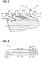
- Fig. 5 is a side view of the second coil-end group 31b viewed from the inside of the stator core 32.
- Fig. 6 is a diagram illustrating a large segment and a small segment
- Fig. 7B is an enlarged view of the indentations in Fig. 6.
- Fig. 8 is a diagram illustrating a large segment and a small segment according to prior art
- Fig. 9 is an enlarged view of the indentation 331h in Fig. 8. As shown in Figs.
- the large and small segments 331 and 332 are formed with indentations 331g, 331h, 332g, and 332h in their respective straight portions 331a, 331b, 332a, and 332b in the faces opposing each other when the turn portions 331c and 332c are aligned with each other in multiple layers.
- These indentations 331g, 331h, 332g, and 332h are provided over an area P that covers intersecting portions 33c where the radially adjacent electrical conductors intersect each other when the segments 33 are bent in the circumferential direction after being inserted into the slots 35.
- indentations 331g, 331h, 332g, and 332h are formed in the opposite side faces of radially adjacent conductor segments over the area P shown in Figs. 5 and 6.
- the conductor segments have a smaller thickness in the area where these indentations 331g, 331h, 332g, and 332h are formed than the radial thickness at either end of the segments 331 and 332.
- a sufficient clearance is secured between each adjacent conductor segment in the area P, which in turn enhances insulation between the conductor segments in the area P at the coil end where they intersect each other. This improves the cooling efficiency when air passes.
- the indentations 331g, 331h, 332g, and 332h of the large and small segments 331 and 332 are formed parallel to the length of their straight portions 331a, 331b, 332a, and 332b, so that the conductor segments have a uniform thickness in their indentations 331g, 331h, 332g, and 332h.
- the indentations 331g, 331h, 332g, and 332h in this embodiment are formed such that the thickness of the segments reduces towards the coil end (where the ends of the segments are bonded together).
- an indentation 331h formed in a segment's straight portion 331b in this embodiment is typically formed such that its depth h1 near the coil end or the end of the conductor segment is larger than the depth h2 that is away from the coil end, or h1>h2.
- the indentations 331g, 331h, 332g, and 332h are formed to have a gradually increasing depth toward the ends where the adjacent conductor segments are bonded together, so that each of the indentations of the segments has a taper shape (the thickness of the segment is reduced towards the ends).
- Fig. 10 is a cross section taken along the line 11a-11a of Fig. 9 in superposed relation with a cross section taken along the line 11b-11b of Fig. 9.
- the 11a-11a cross section shows a cross-sectional configuration of the straight portion of the conductor segment
- the 11b-11b cross section shows a cross-sectional configuration of the indentation 331h of the conductor segment.
- the conductor segment before being formed with the indentation 331h has a rectangular cross section with rounded corners, or a cross section that can be regarded as oval, as shown in Fig. 10.
- Figs. 11A and 11B show cross sections of the conductor segment before and after forming the indentations.
- Fig. 11A is a cross section before forming the indentations (a cross section taken along the line 11a-11a of Fig. 9, and
- Fig. 11B is a cross section after forming the indentations (a cross section taken along the line 11b-11b of Fig. 9.
- W1 represents the width of the conductor segment
- R11 the radius of the rounded corners in the rectangular cross section of the conductor segment before forming the indentation 331h
- R2 the radius of the rounded corners in the rectangular cross section of the conductor segment after forming the indentation 331h.
- the width W1 of the conductor segment remains unchanged before and after forming the indentation. That is, the displacement of the material which occurs when pressing an indentation of a depth h is absorbed by the rounded corners becoming sharper, i.e., by the reduction in radius from R11 to R2 at the rounded corners of the rectangular cross section of the conductor segment.
- Figs. 12A and 12B illustrate a change in the cross-sectional configuration of the conductor segment when forming an indentation in a case in which the conductor segment has a smaller radius R12 than R1 in Fig. 11A at the corners of its rectangular cross section.
- the indentation is to be formed to allow the equation 1 to be established, the depth h' of the indentation will be smaller than the depth h. Therefore, a sufficient clearance will not be secured at the intersecting portions of the conductor segments, and there is the risk of short-circuiting the segments.
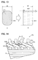
- Figs. 13A and 13B illustrate a change in the cross-sectional configuration of the conductor segment when forming an indentation in a case in which the conductor segment has a larger width W2 than W1 in Fig. 11A.
- the indentation is to be formed while allowing the equation 1 to be established, the depth h" of the indentation will be smaller than the depth h'. Therefore, a sufficient clearance will not be secured at the intersecting portions of the conductor segments, and there is the risk of short-circuiting.
- the indentations cannot be formed with a satisfactory depth for providing sufficient clearances at the intersecting portions of the conductor segments.
- the intersecting portions 33c shown in Fig. 5, particularly near the bonded ends at the coil end, are susceptible to damage in the insulation films such as peeling or cracks because of the heat of welding. Accordingly, it is important to secure sufficient clearances between the conductor segments near the bonded ends.
- the large and small segments 331 and 332 are formed with the indentations 331g, 331h, 332g, and 332h having a reverse taper with their depths increasing towards the segment ends on the opposite side of the turn portions 331c and 332c near the segment ends, which will be bonded together, and therefore they are provided with sufficient clearances near their bonded ends. Further, even if it is difficult to form the indentations with a sufficient depth because of a small corner radius of the rectangular cross section of the conductor segments, or because of a large width of the conductor segments, it is possible to secure satisfactory clearances at intersecting portions of the conductor segments near their bonded ends at the coil end where short-circuiting is most likely to occur.
- vibration of the vehicle will not easily cause radially adjacent electrical conductors at the second coil-end group 31b to contact each other, and thereby the risk of the insulation film 37 being damaged will be reduced. Also, short-circuiting caused by contacts between damaged portions of insulation films 37 is prevented.
- the indentations 331g, 331h, 332g, and 332h are provided over the area P that covers the whole intersecting portions 33c of the radially adjacent conductor segments. However, they need not necessarily span the entire intersecting portions, and may instead, for example, as shown in Fig. 14, cover only the intersecting portions Q near the bonded ends where short-circuiting is most likely to occur.
- Figs. 5 and 14 both show examples in which the conductor segments intersect each other at two points, but if there are more than three intersecting points, the indentations may be provided such as to cover all those three or more intersecting points.
- the indentations 331g, 331h, 332g, and 332h need not necessarily be flat-shaped and may be curved.
- the manufacturing process of the stator 2 of the second embodiment includes: a step of forming indentations in the side faces of each of the conductor segments 331 and 332 by pressing, the indentations being slanted so as to be oriented in the radial direction when the segments are twisted; a step of inserting the conductor segments 331 and 332 in the slots 35 so that they adjoin each other in the radial direction; a step of bending each of the conductor segments and radially adjacent segments (for example, 331a and 332a, and 332b' and 331b') in different circumferential directions at a predetermined pole pitch angle in a twisting fashion such that the indentations formed in the side faces of the adjacent conductor segments (for example, 331a and 332a, and 332b' and 331b') intersect each other in a face-to-face relationship; and a step of bonding the ends of the conductor segments to the ends of the radially adjoining conductor segments (for example, 331d'
- the straight portions 332a and 332b positioned at the inner layer of the coil end are bent in a direction in which the small segment 332 closes, so that their bonded ends 332d and 332e are closer to each other by a pitch of half a pole.
- the second coil-end group 31b is laid out such that radially adjacent electrical conductors are bent in circumferentially opposite directions.
- the large and small segments 331 and 332 may be twisted when being bent as described above. How such a twist would occur in the prior art large and small segments 331 and 332 will be explained below with reference to Figs. 15 and 16.
- Fig. 15 illustrates large and small segments 331 and 332 of Fig. 3 that are inserted in the stator core.
- the large and small segments 331 and 332 are bent in circumferential directions as shown in Fig. 16.
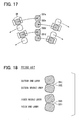
- the large and small segments 331 and 332 are bent in circumferentially opposite directions. Taking one row of bonded ends 331d', 332d, 332e, and 331e' as one example, how the large and small segments 331 and 332 are twisted will be explained with reference to Figs. 15 and 16, and Fig. 17, which is a view taken in the direction of arrow R in Fig. 16.
- Fig. 18 is a cross section across the line 18-18 of Fig. 5 viewed in the direction of arrow S in Fig. 16. The figure shows how the intersecting portions P of the conductor segments are twisted.
- Figs. 19 and 20 are cross sections, taken similarly to Fig. 18, of bond areas 331i, 332i, 331j, and 332j of prior art segments provided with indentations 331g, 331h, 332g, and 332h in the intersecting portions on the same plane as the bond areas of the segments.
- Fig. 19 illustrates the segments which are not twisted
- Fig. 20 illustrates those which are twisted.
- the clearance C2 between the segments in the intersecting portions when they are twisted is clearly smaller than the clearance C1 between the segments when they are not twisted. That is, when the segments are twisted, sufficient clearances cannot be secured in the intersecting portions of the segments, if the indentations are formed on the same plane as the bond areas. Because of this, the insulation films are more susceptible to damage, and short-circuiting is more likely to occur.
- the indentations 331g, 331h, 332g, and 332h are provided as slanted side faces, as shown in Fig. 21, relative to the opposing bond areas of radially adjacent conductor segments.
- the indentations 331g, 331h, 332g, and 332h are oriented radially when the conductor segments are twisted, with opposing indentations 331g and 332g, and indentations 331h and 332h being substantially parallel to each other.
- the clearance C3 in the intersecting portions 33c is much larger than the clearance C2 shown in Fig. 20.
- the broken lines in the figure indicate the cross sections of the segments before forming the indentations by pressing.
- Figs. 22 through 24 illustrate the large and small segments 331 and 332 of the second embodiment before being twisted.
- Fig. 22 is a perspective view
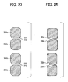
- Fig. 23 is a cross-sectional view taken along the line 23-23 of Fig. 22
- Fig. 24 is a cross-sectional view taken along the line 24-24 of Fig. 22.
- the broken lines in Fig. 24 indicate the cross sections of the segments before forming the indentations by pressing.
- Indentations 331g, 331h, 332g, and 332h are provided over area P (see Figs. 5 and 22) to cover intersecting portions 33c where radially adjacent conductor segments 33, after being inserted into the slots 35, intersect each other when they are twisted in the circumferential direction. Accordingly, similarly to the first embodiment, sufficient clearances are secured in the intersecting portions of the conductor segments at the coil end, whereby damage to their insulation films and resulting short circuits are prevented.
- the twist in the conductor segments is taken into consideration, and so the indentations are formed to be slanted so that they will be oriented radially when the segments are twisted after being inserted into the slots 35.
- Another option is to provide the indentations on a plane parallel to the bond areas in the indentation formation step as in the first embodiment, and, after the segments have been twisted in the bending step, to twist back the segments in an additional step so that the indentations 331g and 332g, and 331h and 332h will face each other in a substantially parallel relationship.
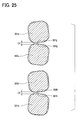
- FIG. 25 is a cross-sectional view of the indentations 331g, 331h, 332g, and 332h in a modified example of the second embodiment, corresponding to Fig. 24 of the second embodiment.
- Broken lines in Fig. 25 indicate the segments before being twisted back in the additional step.
- the clearance C4 in the intersecting portions is made larger than the clearance C2 in Fig. 20, and thus the same effects as those of the second embodiment can be expected.
- the indentations 331g, 331h, 332g, and 332h need not necessarily span all intersecting portions but may cover only part of the intersecting portions near the ends which will be welded to other conductor segments where short-circuiting is more likely to occur. Alternatively, if the segments intersect each other at three or more intersecting points, the indentations may be formed at the three or more intersecting points.
- the indentations 331g, 331h, 332g, and 332h need not necessarily be flat-shaped, but may be curved.
- the distinguishing feature of the third embodiment is that protrusions are formed at the ends (including the bond areas) of the conductor segments at the coil end.
- the protrusions are offset toward the other conductor segments to be bonded.
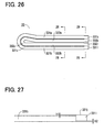
- Fig. 26 illustrates the large and small segments 331 and 332 in the third embodiment.
- the large and small segments 331 and 332 are respectively formed with protrusions 331k, 3311, 332k, and 3321 on the faces of the straight portions 331a, 331b, 332a, and 332b which face each other when the turn portions 331c and 332c are aligned in multiple layers.
- Fig. 27 is an enlarged view near the end of the large segment 331 formed with the protrusion 3311.
- the end of the large segment 331 is protruded, by pressing or the like, toward the side of the other conductor segment, to the bond area of which the bond area 331j of the large segment 331 will be bonded.
- the offset amount h1 of the protrusion 3311 toward that direction on the side of the bond area is equal to the offset amount h2 on the opposite side. (A like arrangement applies to protrusions 331k, 332k, 3321).
- Fig. 28 is a cross-sectional view taken along the line 28-28 of Fig. 26, and Fig. 29 is a cross-sectional view taken along the line 29-29 of Fig. 26.
- the bond areas 331i and 331j, and 332i and 332j are bonded together, whereby a clearance C4 is provided in advance between the large and small segments 331 and 332 as shown in Fig. 28.
- the offset amounts of the protrusions 331k, 3311, 332k, and 3321 in opposite directions are identical, but the same effects will be obtained even if they are different.
- the clearances in the intersecting portions between conductor segments are secured by offsetting the segment ends to be bonded together in mutually approaching directions.
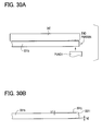
- Another option, as a modified example of the third embodiment, is shown in Figs. 30A and 30B.
- the example involves pressing the end of the straight portion 331b that is secured on a die in a direction perpendicular to the longitudinal direction of segment 331b with a punch as shown in Fig. 30A. This causes bending in the end of the straight portion 331b of the segment toward the side of the bond area 331j, so as to form a protrusion 3311 as shown in Fig. 30B that protrudes toward the other segment to which it is bonded.
- first or the second embodiment with indentations in the straight portions of the segments may be combined with the construction of the third embodiment provided with protrusions at the ends of the conductor segments.
- the conductor segments in the innermost and outermost layers 331a and 331b', respectively have the protrusions of the third embodiment at their ends, while those in the inner-middle and outer-middle layers 332a and 332b', respectively, have the indentations of the second embodiment in their straight portions.
- the reason why the indentations of the second embodiment are not employed for the segments in the innermost and outermost layers 331a and 331b' is as follows. The formation of the indentations of the first or second embodiment causes the corner radius of the rectangular cross section of the conductor segments to become smaller as described above.
- the conductor segments in the innermost and outermost layers 331a and 331b' are provided only with protrusions at their ends toward the bonding direction so as to avoid the reduction in the corner radius of the rectangular cross section of the conductor segments, which is brought about by the formation of indentations.
- the conductor segments in the inner-middle and outer-middle layers 332a and 332b' are formed with indentations in their straight portions.
- the stator for the vehicular rotary electric machine as described in the first aspect of the present invention has an indentation formed in a side face of one electrical conductor opposite to another electrical conductor at their intersecting portion. Since the indentation has a depth gradually increasing towards the end thereof, a sufficient clearance is secured between the electrical conductors in their intersecting portion near the ends, where the insulation films are liable to be damaged by heat at the time of welding. Electrical insulation is thereby ensured, and the cooling efficiency at the coil end is improved.
- stator for the vehicular rotary electric machine even when one electrical conductor is twisted at the coil end, its radial thickness is kept small. Therefore, a sufficient clearance is secured between the electrical conductors, which ensures electrical insulation while improving the cooling efficiency at the coil end.
- the radial indentation is formed in its side face that opposes the other one in a skewed fashion. Therefore, even when one electrical conductor is twisted, its radial thickness is kept small. Accordingly, a sufficient clearance is secured between the electrical conductors, which ensures electrical insulation while improving the cooling efficiency at the coil end.
- the radial indentation is formed in its side face that is brought substantially parallel in a face-to-face relationship with the side face of the other one by twisting back the electrical conductor. Accordingly, even when one electrical conductor is twisted, its radial thickness is kept small. Therefore, a sufficient clearance is secured between electrical conductors, which ensures electrical insulation while improving the cooling efficiency at the coil end.
- the end of the one electrical conductor at the coil end is formed with a protrusion protruding towards the bond area of the other electrical conductor, so that the other portions of the one electrical conductor are kept apart from the other electrical conductor other than the end to be bonded to the other electrical conductor to provide a sufficient clearance therebetween. Electrical insulation is thereby ensured, and the cooling efficiency at the coil end is improved.
- the protrusion is formed by offsetting the end of the one electrical conductor toward the bond area of the other electrical conductor by pressing or the like, the end of electrical conductor is brought closer to the bond area of the other electrical conductor, while the other parts of the electrical conductors other than the end are kept apart from the other electrical conductor.
- the protrusion is formed by bending the end of the one electrical conductor toward the bond area of the other electrical conductor by pressing or the like, the end of the one electrical conductor is brought closer to the bond area of the other electrical conductor.
- the effect of this is that the other parts of the electrical conductors, other than the particular end, are kept apart from the other electrical conductor.
- the one electrical conductor accommodated in at least one layer in the slots is formed with a protrusion at its end that includes a bond area to be bonded to the other radially adjacent electrical conductor at the coil end, the electrical conductor protrusion of the one electrical conductor protruding toward the bond area of the other electrical conductor is kept apart from the other electrical conductor except its end which will be bonded to the other electrical conductor, so as to provide a sufficient clearance therebetween. Electrical insulation is thereby ensured, and the cooling efficiency at the coil end is improved.
- the one electrical conductor accommodated in at least one of the other layers in the slots intersects the other radially adjacent electrical conductor at the coil end at one point or more and is formed with a radial indentation in its side face opposite to the other electrical conductor at any of its intersecting portions. Therefore, a sufficient clearance is provided between the electrical conductors in the intersecting portion. Electrical insulation is thereby ensured, and the cooling efficiency at the coil end is also improved.
- the one electrical conductor in the innermost or outermost layer of the slots is formed with, at its end, a protrusion protruding towards the other electrical conductor but with no indentations. Indentations cause the edges of the electrical conductor to become sharper. Therefore, there is no risk of electrical conductors being caught in the insulation material and no risk of the conductors becoming crooked when being inserted into the slots. They can thus be smoothly inserted into the slots.
- radially adjoining electrical conductors are formed with indentations in their side faces such that these indentations cross each other with a face-to-face relationship. Therefore, the radial thickness of the electrical conductors in their intersecting portions is made smaller, whereby clearances between electrical conductors are readily and reliably secured.
- the indentation formed in the one electrical conductor has a depth gradually increasing towards the end, a sufficient clearance is secured between the electrical conductors in the intersecting portion near the ends. Electrical insulation is thereby ensured, and the cooling efficiency at the coil end is improved. Also, even when the electrical conductor has a small radius in the corners of the rectangular cross section, or even when the conductor segment has a large width, the indentation is readily and reliably secured with a sufficient depth near the end of the electrical conductor.
- the opposing indentations are made substantially parallel to each other by twisting back the electrical conductors in the intersecting portions. Accordingly, the radial thickness is kept small, and sufficient clearances are secured between electrical conductors at their intersecting portions.
Landscapes
- Engineering & Computer Science (AREA)
- Power Engineering (AREA)
- Manufacturing & Machinery (AREA)
- Windings For Motors And Generators (AREA)
- Manufacture Of Motors, Generators (AREA)
- Insulation, Fastening Of Motor, Generator Windings (AREA)
Abstract
Description
Claims (13)
- A stator (2) for a vehicular rotary electric machine comprising:a stator core (32) having a plurality of slots (35); anda multi-phase stator winding constructed of a plurality of electrical conductors (331a, 332a, 331b, 332b) connected together, said electrical conductors (331a, 332a, 331b, 332b) being accommodated radially side-by-side within said slots (35) and electrically insulated from each other, and having their ends extending to an outside of said slots (35) and being bonded together to form a coil end (31b), whereina first electrical conductor at said coil end (31b) is arranged to intersect a second electrical conductor at one point or more, the second electrical conductor adjoining the first electrical conductor in a radial direction, and a radial indentation is formed in a side face of the first electrical conductor opposite to the second electrical conductor at least at one intersecting point between the adjacent electrical conductors, the indentation having a depth that increases toward one end of the first electrical conductor.
- A stator for a vehicular rotary electric machine comprising:a stator core (32) having a plurality of slots (35); anda multi-phase stator winding constructed of a plurality of electrical conductors (331a, 332a, 331b, 332b) connected together, said electrical conductors (331a, 332a, 331b, 332b) being accommodated radially side-by-side within said slots (35) and electrically insulated from each other, and having their ends extending to an outside of said slots (35) and being bonded together to form a coil end (31b), whereina first electrical conductor at said coil end (31b) is arranged to be mounted in said stator core (32) in a twisted condition and to intersect a second electrical conductor at one point or more along its twisted portion, the second electrical conductor adjoining the first electrical conductor in a radial direction, anda side face of the first electrical conductor defines a radial indentation opposite to the second electrical conductor at any intersecting points.
- The stator for a vehicular rotary electric machine according to claim 2, wherein the side face of the first electrical conductor and the side face of the second electrical conductor face each other in a skewed fashion at said intersecting point, the radial indentation being provided in said skewed opposing side face of the first electrical conductor.
- The stator for a vehicular rotary electric machine according to claim 2, wherein said twisted portion is twisted back in an opposite direction at said intersecting point so that the side face of said first electrical conductor is substantially parallel to the side face of said second electrical conductor, the radial indentation being provided in said parallel opposite side faces of the electrical conductors.
- A stator for a vehicular rotary electric machine comprising:a stator core (32) having a plurality of slots (35); anda multi-phase stator winding constructed of a plurality of electrical conductors (331a, 332a, 331b, 332b) connected together, said electrical conductors (331a, 332a, 331b, 332b) being accommodated radially side-by-side within said slots and electrically insulated from each other, and having their ends extending to an outside of said slots (35) and being bonded together to form a coil end (31b), whereina first electrical conductor at the coil end (31b) has a bond area end to be bonded to a second electrical conductor, the second electrical conductor adjoining the first electrical conductor in a radial direction, said bond area end being provided with a protrusion protruding toward a bond area of the second electrical conductor.
- The stator for a vehicular rotary electric machine according to claim 5, wherein said protrusion is formed by offsetting said end toward the bond area end of the second electrical conductor.
- The stator for a vehicular rotary electric machine according to claim 5, wherein said protrusion is formed by bending said end towards the bond area of the second electrical conductor.
- A stator for a vehicular rotary electric machine comprising:a stator core (32) having a plurality of slots (35); anda multi-phase stator winding constructed of a plurality of electrical conductors (331a, 332a, 331b, 332b) connected together, said electrical conductors (331a, 332a, 331b, 332b) being accommodated radially side-by-side within said slots (35) and electrically insulated from each other, and having their ends extending to an outside of said slots (35) and being bonded together to form a coil end (31b), whereina first electrical conductor accommodated in at least one layer in said slots (35) is formed with a protrusion at its end that includes a bond area to be bonded to a second radially adjacent electrical conductor at said coil end (31b), anda third electrical conductor accommodated in at least one of the other layers in said slots crosses the second radially adjacent electrical conductor at said coil end (31b) at one point or more and is formed with a radial indentation in its side face opposite to the second electrical conductor at any of its intersecting portions.
- The stator for a vehicular rotary electric machine according to claim 8, wherein said at least one layer is either an innermost or an outermost layer in said slots, and said at least one of the other layers is a layer other than the innermost and the outermost layers in said slots.
- A manufacturing method of a stator (2) for a vehicular rotary electric machine including a stator core (32) having a plurality of slots (35), and a multi-phase stator winding constructed of a plurality of electrical conductors (331a, 332a, 331b, 332b) connected together, said electrical conductors (331a, 332a, 331b, 332b) being accommodated radially side-by-side within said slots (35) and electrically insulated from each other, and having their ends extending to an outside of said slots (35) and being bonded together to form a coil end (31b), the method comprising the steps of:forming an indentation in a radial direction in a side face of each of the electrical conductors (331a, 332a, 331b, 332b) by pressing;inserting said plurality of electrical conductors (331a, 332a, 331b, 332b) in a radially side-by-side relationship with each other in the slots (35);bending each of the electrical conductors (331a, 332a, 331b, 332b) and radially adjacent electrical conductors (331a, 332a, 331b, 332b) in different circumferential directions by a predetermined pole pitch such that the indentations formed in respective side faces of the adjacent electrical conductors pass each other in a face-to-face relationship; andbonding one end of each of said electrical conductors (331a, 332a, 331b, 332b) to one end of the adjacent electrical conductors.
- A manufacturing method of a stator (32) for a vehicular rotary electric machine according to claim 11, wherein said indentations are provided by pressing such that their depth increases towards one end of said electrical conductors.
- A manufacturing method of a stator for a vehicular rotary electric machine according to claim 10, wherein, in the bending step, the electrical conductors (331a, 332a, 331b, 332b) are clamped at their ends and bent so as to be twisted, and said bending step includes an additional step of twisting back said electrical conductors (331a, 332a, 331b, 332b) in an opposite direction at said intersecting point between the radially adjacent electrical conductors so that the indentations are faced to the indentations of said radially adjacent electrical conductors in a substantially parallel face-to-face relationship with each other.
- A manufacturing method of a stator (32) for a vehicular rotary electric machine according to claim 11, wherein, in the bending step, the electrical conductors (331a, 332a, 331b, 332b) are clamped at their ends and bent so as to be twisted, and said bending step includes an additional step of twisting back said electrical conductors (331a, 332a, 331b, 332b) in an opposite direction at said intersecting point between the radially adjacent electrical conductors so that the indentations are faced to the indentations of said radially adjacent electrical conductors in a substantially parallel face-to-face relationship with each other.
Priority Applications (2)
| Application Number | Priority Date | Filing Date | Title |
|---|---|---|---|
| EP05011481A EP1566877B1 (en) | 2002-01-18 | 2003-01-14 | Stator for a rotary electric machine |
| EP05011482A EP1566878B1 (en) | 2002-01-18 | 2003-01-14 | Stator of a rotary electric machine and manufacturing method thereof |
Applications Claiming Priority (2)
| Application Number | Priority Date | Filing Date | Title |
|---|---|---|---|
| JP2002009861 | 2002-01-18 | ||
| JP2002009861A JP3738733B2 (en) | 2002-01-18 | 2002-01-18 | Stator for rotating electrical machine for vehicle and method for manufacturing the same |
Related Child Applications (2)
| Application Number | Title | Priority Date | Filing Date |
|---|---|---|---|
| EP05011481A Division EP1566877B1 (en) | 2002-01-18 | 2003-01-14 | Stator for a rotary electric machine |
| EP05011482A Division EP1566878B1 (en) | 2002-01-18 | 2003-01-14 | Stator of a rotary electric machine and manufacturing method thereof |
Publications (3)
| Publication Number | Publication Date |
|---|---|
| EP1330012A2 true EP1330012A2 (en) | 2003-07-23 |
| EP1330012A3 EP1330012A3 (en) | 2004-06-02 |
| EP1330012B1 EP1330012B1 (en) | 2006-07-26 |
Family
ID=19191546
Family Applications (3)
| Application Number | Title | Priority Date | Filing Date |
|---|---|---|---|
| EP05011481A Expired - Lifetime EP1566877B1 (en) | 2002-01-18 | 2003-01-14 | Stator for a rotary electric machine |
| EP03000798A Expired - Lifetime EP1330012B1 (en) | 2002-01-18 | 2003-01-14 | Stator of a rotary electric machine and manufacturing method thereof |
| EP05011482A Expired - Lifetime EP1566878B1 (en) | 2002-01-18 | 2003-01-14 | Stator of a rotary electric machine and manufacturing method thereof |
Family Applications Before (1)
| Application Number | Title | Priority Date | Filing Date |
|---|---|---|---|
| EP05011481A Expired - Lifetime EP1566877B1 (en) | 2002-01-18 | 2003-01-14 | Stator for a rotary electric machine |
Family Applications After (1)
| Application Number | Title | Priority Date | Filing Date |
|---|---|---|---|
| EP05011482A Expired - Lifetime EP1566878B1 (en) | 2002-01-18 | 2003-01-14 | Stator of a rotary electric machine and manufacturing method thereof |
Country Status (5)
| Country | Link |
|---|---|
| US (3) | US6897594B2 (en) |
| EP (3) | EP1566877B1 (en) |
| JP (1) | JP3738733B2 (en) |
| CN (1) | CN1249886C (en) |
| DE (3) | DE60306966T2 (en) |
Cited By (4)
| Publication number | Priority date | Publication date | Assignee | Title |
|---|---|---|---|---|
| EP1347559A2 (en) | 2002-03-20 | 2003-09-24 | Denso Corporation | Wound stator of a rotary electric machine and its winding method |
| FR2895586A1 (en) * | 2005-12-02 | 2007-06-29 | Denso Corp | ROTATING ELECTRICAL MACHINE, REINFORCEMENT, METHOD FOR MANUFACTURING ROTATING ELECTRIC MACHINE, AND MACHINE FOR FORMING REINFORCEMENT |
| EP2244356A3 (en) * | 2009-04-24 | 2017-07-05 | Hitachi Automotive Systems, Ltd. | Rotating electric machine for driving a vehicle and vehicle equipped with the same |
| WO2024046522A1 (en) * | 2022-08-29 | 2024-03-07 | Schaeffler Technologies AG & Co. KG | Stator and kit-of-parts |
Families Citing this family (91)
| Publication number | Priority date | Publication date | Assignee | Title |
|---|---|---|---|---|
| JP3738733B2 (en) * | 2002-01-18 | 2006-01-25 | 株式会社デンソー | Stator for rotating electrical machine for vehicle and method for manufacturing the same |
| JP4626312B2 (en) * | 2004-01-19 | 2011-02-09 | 株式会社デンソー | Manufacturing method of winding of rotating electric machine |
| US8062991B2 (en) * | 2004-12-22 | 2011-11-22 | General Electric Company | Catalyst system and method for the reduction of NOx |
| JP2007006634A (en) * | 2005-06-24 | 2007-01-11 | Hitachi Global Storage Technologies Netherlands Bv | Disk device and disk drive device |
| US7536526B2 (en) * | 2005-07-11 | 2009-05-19 | General Electric Company | Hierarchical state based migration of structured data |
| JP4923545B2 (en) * | 2005-12-02 | 2012-04-25 | 株式会社デンソー | Rotating electric machine |
| JP4497102B2 (en) * | 2006-02-10 | 2010-07-07 | 株式会社デンソー | Rotating electrical machine stator for vehicles |
| JP2008131826A (en) * | 2006-11-24 | 2008-06-05 | Toyota Motor Corp | Motor stator and method for manufacturing motor stator |
| JP4412330B2 (en) * | 2007-02-09 | 2010-02-10 | 株式会社デンソー | Stator winding of rotating electric machine and method of manufacturing the same |
| TWI392196B (en) * | 2009-06-30 | 2013-04-01 | Victory Ind Corp | Method of Making Stirrups for Automobile Generators |
| JP5569289B2 (en) * | 2010-01-22 | 2014-08-13 | 株式会社デンソー | Rotating electric machine stator |
| JP5370245B2 (en) * | 2010-03-31 | 2013-12-18 | 株式会社デンソー | Manufacturing method of stator of rotating electric machine |
| US20110260572A1 (en) * | 2010-04-27 | 2011-10-27 | Honda Motor Co., Ltd. | Motor stator and manufacturing method of motor stator |
| EP2567450A4 (en) | 2010-05-04 | 2018-01-17 | Remy Technologies, LLC | Electric machine cooling system and method |
| JP5482423B2 (en) * | 2010-05-11 | 2014-05-07 | 株式会社デンソー | Electric motor |
| US8659191B2 (en) | 2010-05-18 | 2014-02-25 | Remy Technologies, Llc | Sleeve member for an electric machine |
| DE112011101912T5 (en) | 2010-06-04 | 2013-03-28 | Remy Technologies Llc. | Cooling system and method for an electric machine |
| US8269383B2 (en) * | 2010-06-08 | 2012-09-18 | Remy Technologies, Llc | Electric machine cooling system and method |
| JP2013528353A (en) | 2010-06-08 | 2013-07-08 | レミー テクノロジーズ リミテッド ライアビリティー カンパニー | Electromechanical cooling system and method |
| US8456046B2 (en) * | 2010-06-08 | 2013-06-04 | Remy Technologies, Llc | Gravity fed oil cooling for an electric machine |
| US8519581B2 (en) | 2010-06-08 | 2013-08-27 | Remy Technologies, Llc | Electric machine cooling system and method |
| US8614538B2 (en) | 2010-06-14 | 2013-12-24 | Remy Technologies, Llc | Electric machine cooling system and method |
| US8552600B2 (en) | 2010-06-14 | 2013-10-08 | Remy Technologies, Llc | Potted end turns of an electric machine |
| US8482169B2 (en) | 2010-06-14 | 2013-07-09 | Remy Technologies, Llc | Electric machine cooling system and method |
| CN103098355B (en) * | 2010-07-28 | 2015-09-30 | 泰克马奇有限公司 | Apparatus and method for preformed conductor bars for bar windings of twisting electrical machines |
| DE102010037588A1 (en) * | 2010-09-16 | 2012-03-22 | Lloyd Dynamowerke Gmbh & Co. Kg | Segment for use in stator, for electrical machine, has grooves for receiving array of coils arranged in first and second layers, where sides of coil in another array of coils are arranged in third layer |
| US8446056B2 (en) | 2010-09-29 | 2013-05-21 | Remy Technologies, Llc | Electric machine cooling system and method |
| US8395287B2 (en) | 2010-10-04 | 2013-03-12 | Remy Technologies, Llc | Coolant channels for electric machine stator |
| US8492952B2 (en) | 2010-10-04 | 2013-07-23 | Remy Technologies, Llc | Coolant channels for electric machine stator |
| US8593021B2 (en) | 2010-10-04 | 2013-11-26 | Remy Technologies, Llc | Coolant drainage system and method for electric machines |
| US8508085B2 (en) | 2010-10-04 | 2013-08-13 | Remy Technologies, Llc | Internal cooling of stator assembly in an electric machine |
| US8546983B2 (en) | 2010-10-14 | 2013-10-01 | Remy Technologies, Llc | Split drain system and method for an electric machine module |
| US8648506B2 (en) | 2010-11-09 | 2014-02-11 | Remy Technologies, Llc | Rotor lamination cooling system and method |
| US8497608B2 (en) | 2011-01-28 | 2013-07-30 | Remy Technologies, Llc | Electric machine cooling system and method |
| WO2012145302A2 (en) | 2011-04-18 | 2012-10-26 | Remy Technologies, Llc | Electric machine module cooling system and method |
| US8692425B2 (en) | 2011-05-10 | 2014-04-08 | Remy Technologies, Llc | Cooling combinations for electric machines |
| US8803380B2 (en) | 2011-06-03 | 2014-08-12 | Remy Technologies, Llc | Electric machine module cooling system and method |
| US20130002067A1 (en) * | 2011-06-30 | 2013-01-03 | Bradfield Michael D | Electric Machine Module Cooling System and Method |
| US9041260B2 (en) | 2011-07-08 | 2015-05-26 | Remy Technologies, Llc | Cooling system and method for an electronic machine |
| US8803381B2 (en) | 2011-07-11 | 2014-08-12 | Remy Technologies, Llc | Electric machine with cooling pipe coiled around stator assembly |
| US8546982B2 (en) | 2011-07-12 | 2013-10-01 | Remy Technologies, Llc | Electric machine module cooling system and method |
| US9048710B2 (en) | 2011-08-29 | 2015-06-02 | Remy Technologies, Llc | Electric machine module cooling system and method |
| US8975792B2 (en) | 2011-09-13 | 2015-03-10 | Remy Technologies, Llc | Electric machine module cooling system and method |
| US8901789B2 (en) | 2011-10-07 | 2014-12-02 | Remy Technologies, Llc | Electric machine module |
| EP2582019A1 (en) * | 2011-10-14 | 2013-04-17 | Siemens Aktiengesellschaft | Adjusting the stiffness in the stator end winding of an electrical machine |
| US8866361B2 (en) * | 2011-10-17 | 2014-10-21 | GM Global Technology Operations LLC | Bar conductor shapes for electric machines |
| US20130093280A1 (en) * | 2011-10-17 | 2013-04-18 | GM Global Technology Operations LLC | Multi-filar bar conductors for electric machines |
| US9099900B2 (en) | 2011-12-06 | 2015-08-04 | Remy Technologies, Llc | Electric machine module cooling system and method |
| US20130187494A1 (en) * | 2012-01-25 | 2013-07-25 | Remy Technologies, L.L.C. | Stator assembly for an electric machine |
| JP5789538B2 (en) | 2012-02-14 | 2015-10-07 | 日立オートモティブシステムズ株式会社 | Rotating electric machine and method of manufacturing rotating electric machine |
| US20130221773A1 (en) * | 2012-02-23 | 2013-08-29 | Bradley D. Chamberlin | Electric machine module |
| JP5638723B2 (en) | 2012-03-19 | 2014-12-10 | 三菱電機株式会社 | Stator for rotating electrical machine for vehicle and method for manufacturing the same |
| US9331543B2 (en) | 2012-04-05 | 2016-05-03 | Remy Technologies, Llc | Electric machine module cooling system and method |
| US8443509B1 (en) * | 2012-04-18 | 2013-05-21 | GM Global Technology Operations LLC | Preparing bar-wound stator conductors for electrical interconnection |
| US10069375B2 (en) | 2012-05-02 | 2018-09-04 | Borgwarner Inc. | Electric machine module cooling system and method |
| JP5594544B2 (en) | 2012-07-31 | 2014-09-24 | 株式会社デンソー | Stator for rotating electric machine and method for manufacturing the same |
| US9106120B2 (en) * | 2012-10-09 | 2015-08-11 | Remy Technologies, L.L.C. | Method for twisting an armature |
| JP5724984B2 (en) * | 2012-10-19 | 2015-05-27 | トヨタ自動車株式会社 | Rotating electric machine stator |
| JP5924711B2 (en) * | 2012-10-22 | 2016-05-25 | 三菱電機株式会社 | Manufacturing method of winding body used for armature winding for electric machine |
| CN105191071B (en) * | 2013-02-18 | 2017-09-26 | 三菱电机株式会社 | rotating electrical machine |
| CN105794089B (en) * | 2013-11-29 | 2018-06-26 | 三菱电机株式会社 | Armature of electrical machinery |
| JP6402517B2 (en) * | 2014-07-14 | 2018-10-10 | 株式会社デンソー | Method for manufacturing conductor member, conductor member, stator, and motor |
| EP3021467B1 (en) * | 2014-11-14 | 2017-08-16 | Magneti Marelli S.p.A. | Method and station for the construction of a stator winding with rigid bars for a rotary electrical machine |
| CN107005134B (en) * | 2014-12-26 | 2019-02-26 | 日立汽车系统株式会社 | Coil forming device and coil of rotating electrical machine |
| KR20160116568A (en) * | 2015-03-30 | 2016-10-10 | 현대자동차주식회사 | Motor unit hving insulation member |
| WO2017014217A1 (en) * | 2015-07-23 | 2017-01-26 | アイシン・エィ・ダブリュ株式会社 | Stator and method of manufacturing stator |
| JP6233384B2 (en) * | 2015-10-29 | 2017-11-22 | トヨタ自動車株式会社 | Coil end joining method for stator segment coil |
| US10063117B2 (en) * | 2016-03-08 | 2018-08-28 | Hitachi Automotive Systems, Ltd. | Dynamo-electric machine with stator having trapezoid shape segmented coil |
| JP6364465B2 (en) * | 2016-12-09 | 2018-07-25 | 本田技研工業株式会社 | Slot coil and stator of rotating electric machine |
| CN106655638B (en) * | 2016-12-12 | 2019-03-29 | 浙江安美德汽车配件有限公司 | Low-noise high-efficiency AC generator for vehicle based on LIN bus |
| CN110291698B (en) * | 2017-02-14 | 2021-06-22 | 电装多利牡株式会社 | Rotating electric machine and method for manufacturing same |
| JP6642494B2 (en) | 2017-03-10 | 2020-02-05 | トヨタ自動車株式会社 | Manufacturing equipment for stators of rotating electric machines |
| JP6680815B2 (en) * | 2018-02-07 | 2020-04-15 | 本田技研工業株式会社 | Method and apparatus for bending electric conductor |
| CN108282043A (en) * | 2018-03-21 | 2018-07-13 | 苏州阿福机器人有限公司 | A kind of motor welding winding |
| US10916985B2 (en) * | 2018-04-04 | 2021-02-09 | GM Global Technology Operations LLC | Method of forming a stator assembly |
| JP6962275B2 (en) | 2018-05-30 | 2021-11-05 | トヨタ自動車株式会社 | Motor stator and its manufacturing method |
| CN110784045B (en) * | 2018-07-29 | 2021-09-21 | 比亚迪股份有限公司 | Stator assembly and motor with same |
| CN110784046B (en) * | 2018-07-29 | 2021-10-22 | 比亚迪股份有限公司 | Stator assembly and motor having the same |
| CN110784044B (en) * | 2018-07-29 | 2021-12-07 | 比亚迪股份有限公司 | Stator assembly and motor with same |
| CN110971040B (en) * | 2018-09-28 | 2021-09-03 | 比亚迪股份有限公司 | Stator assembly and motor with same |
| JP7125360B2 (en) * | 2019-02-05 | 2022-08-24 | 日立Astemo株式会社 | Rotating electric machine and manufacturing method of rotating electric machine |
| NO345646B1 (en) * | 2019-02-06 | 2021-05-25 | Kongsberg Maritime CM AS | Distributed double litz wire winding in open slots |
| CN113875128B (en) * | 2019-06-07 | 2025-02-21 | 日立安斯泰莫株式会社 | Stator and terminal block of rotating electrical machine and rotating electrical machine |
| WO2021059426A1 (en) * | 2019-09-26 | 2021-04-01 | 株式会社 東芝 | Coil, and dynamo-electric machine |
| JP7354782B2 (en) * | 2019-11-11 | 2023-10-03 | 株式会社デンソー | Rotating electric machine and manufacturing method of rotating electric machine |
| DE102020205684A1 (en) * | 2020-05-06 | 2021-11-11 | Robert Bosch Gesellschaft mit beschränkter Haftung | Stator of an electrical machine |
| JP7435431B2 (en) * | 2020-12-15 | 2024-02-21 | トヨタ紡織株式会社 | Armature manufacturing method |
| FR3121297A1 (en) * | 2021-03-29 | 2022-09-30 | Nidec Psa Emotors | Electrical conductor for stator of rotating electrical machine and manufacturing method |
| JP2023017570A (en) | 2021-07-26 | 2023-02-07 | 株式会社デンソー | Stator and stator manufacturing method |
| EP4160875A1 (en) * | 2021-10-01 | 2023-04-05 | Valeo eAutomotive Germany GmbH | Shaped conductor for winding an active part of a rotating electric machine, active part for a rotating electric machine and method of manufacturing the same |
| JP7852730B2 (en) * | 2022-09-26 | 2026-04-28 | 日産自動車株式会社 | Stator of a rotating electric machine |
Family Cites Families (21)
| Publication number | Priority date | Publication date | Assignee | Title |
|---|---|---|---|---|
| US1789129A (en) * | 1927-12-08 | 1931-01-13 | Vincent G Apple | Bar winding |
| US1834926A (en) * | 1930-02-05 | 1931-12-08 | Vincent G Apple | Method of making winding loops for bar wound armatures |
| JPS6036698B2 (en) | 1977-11-04 | 1985-08-22 | 株式会社安川電機 | How to wind a concentric coil |
| JPS60170448A (en) | 1984-02-10 | 1985-09-03 | Matsushita Electric Works Ltd | Manufacturing method of iron-free core armature |
| JP3285459B2 (en) | 1995-01-30 | 2002-05-27 | 株式会社日立製作所 | Rotating electric machine and method for forming rotating armature for rotating electric machine |
| US5952749A (en) * | 1997-05-26 | 1999-09-14 | Denso Corporation | Cooling arrangement of alternator |
| WO1998054822A1 (en) * | 1997-05-26 | 1998-12-03 | Denso Corporation | Ac generator for vehicle |
| ES2203986T5 (en) * | 1997-10-16 | 2007-12-01 | Denso Corporation | METHOD AND APPLIANCE FOR ROLLING THE RETURN PARTS OF STATOR DRIVING SEGMENTS IN U. |
| US6181043B1 (en) * | 1997-12-10 | 2001-01-30 | Denso Corporation | Alternator for vehicle |
| JP3196738B2 (en) * | 1998-09-11 | 2001-08-06 | 株式会社デンソー | Stator manufacturing apparatus and stator manufacturing method |
| JP3284981B2 (en) * | 1998-11-02 | 2002-05-27 | 株式会社デンソー | Method for manufacturing vehicle alternator and stator thereof |
| JP3250533B2 (en) * | 1998-11-25 | 2002-01-28 | 株式会社デンソー | Stator for vehicle alternator and method of manufacturing the same |
| JP3988303B2 (en) | 1999-03-19 | 2007-10-10 | 株式会社デンソー | Stator manufacturing method and manufacturing apparatus thereof |
| DE10016151A1 (en) * | 1999-04-02 | 2000-10-05 | Denso Corp | Stator of rotating electrical machine production method, involves providing several U shaped base conductor segments and several shaped connection conductor segments |
| JP3508687B2 (en) * | 1999-07-12 | 2004-03-22 | 株式会社デンソー | Rotating electric machine |
| DE10103935A1 (en) | 2000-02-03 | 2001-08-09 | Denso Corp | Stator arrangement of an electric rotating machine for a vehicle |
| JP3707673B2 (en) | 2000-02-03 | 2005-10-19 | 株式会社デンソー | Rotating electrical machine stator for vehicles |
| JP4187914B2 (en) * | 2000-08-29 | 2008-11-26 | 三菱電機株式会社 | Rotating electric machine stator |
| JP3964116B2 (en) | 2000-09-12 | 2007-08-22 | 三菱電機株式会社 | Rotating electric machine stator |
| JP3738733B2 (en) * | 2002-01-18 | 2006-01-25 | 株式会社デンソー | Stator for rotating electrical machine for vehicle and method for manufacturing the same |
| JP3829769B2 (en) * | 2002-07-18 | 2006-10-04 | 株式会社デンソー | Method for manufacturing stator winding of rotating electric machine |
-
2002
- 2002-01-18 JP JP2002009861A patent/JP3738733B2/en not_active Expired - Lifetime
-
2003
- 2003-01-14 EP EP05011481A patent/EP1566877B1/en not_active Expired - Lifetime
- 2003-01-14 US US10/341,394 patent/US6897594B2/en not_active Expired - Lifetime
- 2003-01-14 DE DE60306966T patent/DE60306966T2/en not_active Expired - Lifetime
- 2003-01-14 EP EP03000798A patent/EP1330012B1/en not_active Expired - Lifetime
- 2003-01-14 DE DE60321814T patent/DE60321814D1/en not_active Expired - Lifetime
- 2003-01-14 DE DE60322939T patent/DE60322939D1/en not_active Expired - Lifetime
- 2003-01-14 EP EP05011482A patent/EP1566878B1/en not_active Expired - Lifetime
- 2003-01-17 CN CN03100733.3A patent/CN1249886C/en not_active Expired - Lifetime
-
2005
- 2005-01-03 US US11/026,034 patent/US7034429B2/en not_active Expired - Fee Related
- 2005-05-24 US US11/135,445 patent/US7287311B2/en not_active Expired - Fee Related
Cited By (6)
| Publication number | Priority date | Publication date | Assignee | Title |
|---|---|---|---|---|
| EP1347559A2 (en) | 2002-03-20 | 2003-09-24 | Denso Corporation | Wound stator of a rotary electric machine and its winding method |
| EP1347559A3 (en) * | 2002-03-20 | 2004-11-24 | Denso Corporation | Wound stator of a rotary electric machine and its winding method |
| US6903478B2 (en) | 2002-03-20 | 2005-06-07 | Denso Corporation | Winding for electric rotating machine and manufacturing method for the same |
| FR2895586A1 (en) * | 2005-12-02 | 2007-06-29 | Denso Corp | ROTATING ELECTRICAL MACHINE, REINFORCEMENT, METHOD FOR MANUFACTURING ROTATING ELECTRIC MACHINE, AND MACHINE FOR FORMING REINFORCEMENT |
| EP2244356A3 (en) * | 2009-04-24 | 2017-07-05 | Hitachi Automotive Systems, Ltd. | Rotating electric machine for driving a vehicle and vehicle equipped with the same |
| WO2024046522A1 (en) * | 2022-08-29 | 2024-03-07 | Schaeffler Technologies AG & Co. KG | Stator and kit-of-parts |
Also Published As
| Publication number | Publication date |
|---|---|
| EP1566877B1 (en) | 2008-06-25 |
| CN1433122A (en) | 2003-07-30 |
| US7034429B2 (en) | 2006-04-25 |
| DE60322939D1 (en) | 2008-09-25 |
| JP3738733B2 (en) | 2006-01-25 |
| EP1566878B1 (en) | 2008-08-13 |
| EP1330012B1 (en) | 2006-07-26 |
| DE60321814D1 (en) | 2008-08-07 |
| EP1566878A1 (en) | 2005-08-24 |
| CN1249886C (en) | 2006-04-05 |
| DE60306966D1 (en) | 2006-09-07 |
| US20030135980A1 (en) | 2003-07-24 |
| US20050217105A1 (en) | 2005-10-06 |
| EP1330012A3 (en) | 2004-06-02 |
| US20050116571A1 (en) | 2005-06-02 |
| US6897594B2 (en) | 2005-05-24 |
| JP2003219588A (en) | 2003-07-31 |
| EP1566877A1 (en) | 2005-08-24 |
| US7287311B2 (en) | 2007-10-30 |
| DE60306966T2 (en) | 2007-09-06 |
Similar Documents
| Publication | Publication Date | Title |
|---|---|---|
| EP1566877B1 (en) | Stator for a rotary electric machine | |
| US6388358B1 (en) | Stator of AC-generator and method of manufacturing the same | |
| US6760965B2 (en) | Method for manufacturing an alternator | |
| KR100399739B1 (en) | Alternator | |
| US7210215B2 (en) | Method of manufacturing stator winding of rotary electric machine | |
| US6373163B1 (en) | Stator for an alternator | |
| US6396185B1 (en) | Alternator | |
| KR100385677B1 (en) | Alternator | |
| JP3775317B2 (en) | Manufacturing method of winding of rotating electric machine | |
| US6501204B1 (en) | Stator for an alternator | |
| KR100397042B1 (en) | Alternator | |
| JP3438581B2 (en) | AC generator for vehicles | |
| JP3427748B2 (en) | AC generator for vehicles | |
| EP1109289B1 (en) | Winding connections for the stator of an alternator | |
| KR100396805B1 (en) | Method for manufacturing an alternator | |
| EP1109299B9 (en) | Method for manufacturing an alternator | |
| EP1109290B1 (en) | Stator windings of an alternator |
Legal Events
| Date | Code | Title | Description |
|---|---|---|---|
| PUAI | Public reference made under article 153(3) epc to a published international application that has entered the european phase |
Free format text: ORIGINAL CODE: 0009012 |
|
| AK | Designated contracting states |
Designated state(s): AT BE BG CH CY CZ DE DK EE ES FI FR GB GR HU IE IT LI LU MC NL PT SE SI SK TR |
|
| AX | Request for extension of the european patent |
Extension state: AL LT LV MK RO |
|
| PUAL | Search report despatched |
Free format text: ORIGINAL CODE: 0009013 |
|
| AK | Designated contracting states |
Kind code of ref document: A3 Designated state(s): AT BE BG CH CY CZ DE DK EE ES FI FR GB GR HU IE IT LI LU MC NL PT SE SI SK TR |
|
| AX | Request for extension of the european patent |
Extension state: AL LT LV MK RO |
|
| RIC1 | Information provided on ipc code assigned before grant |
Ipc: 7H 02K 3/12 B Ipc: 7H 02K 3/50 A |
|
| 17P | Request for examination filed |
Effective date: 20041012 |
|
| AKX | Designation fees paid |
Designated state(s): DE FR GB IT |
|
| 17Q | First examination report despatched |
Effective date: 20050121 |
|
| GRAP | Despatch of communication of intention to grant a patent |
Free format text: ORIGINAL CODE: EPIDOSNIGR1 |
|
| GRAS | Grant fee paid |
Free format text: ORIGINAL CODE: EPIDOSNIGR3 |
|
| GRAA | (expected) grant |
Free format text: ORIGINAL CODE: 0009210 |
|
| AK | Designated contracting states |
Kind code of ref document: B1 Designated state(s): DE FR GB IT |
|
| PG25 | Lapsed in a contracting state [announced via postgrant information from national office to epo] |
Ref country code: IT Free format text: LAPSE BECAUSE OF FAILURE TO SUBMIT A TRANSLATION OF THE DESCRIPTION OR TO PAY THE FEE WITHIN THE PRESCRIBED TIME-LIMIT;WARNING: LAPSES OF ITALIAN PATENTS WITH EFFECTIVE DATE BEFORE 2007 MAY HAVE OCCURRED AT ANY TIME BEFORE 2007. THE CORRECT EFFECTIVE DATE MAY BE DIFFERENT FROM THE ONE RECORDED. Effective date: 20060726 |
|
| REG | Reference to a national code |
Ref country code: GB Ref legal event code: FG4D |
|
| REF | Corresponds to: |
Ref document number: 60306966 Country of ref document: DE Date of ref document: 20060907 Kind code of ref document: P |
|
| ET | Fr: translation filed | ||
| PLBE | No opposition filed within time limit |
Free format text: ORIGINAL CODE: 0009261 |
|
| STAA | Information on the status of an ep patent application or granted ep patent |
Free format text: STATUS: NO OPPOSITION FILED WITHIN TIME LIMIT |
|
| 26N | No opposition filed |
Effective date: 20070427 |
|
| REG | Reference to a national code |
Ref country code: FR Ref legal event code: PLFP Year of fee payment: 14 |
|
| REG | Reference to a national code |
Ref country code: FR Ref legal event code: PLFP Year of fee payment: 15 |
|
| REG | Reference to a national code |
Ref country code: FR Ref legal event code: PLFP Year of fee payment: 16 |
|
| PGFP | Annual fee paid to national office [announced via postgrant information from national office to epo] |
Ref country code: GB Payment date: 20200123 Year of fee payment: 18 Ref country code: DE Payment date: 20200121 Year of fee payment: 18 Ref country code: IT Payment date: 20200131 Year of fee payment: 18 |
|
| PGFP | Annual fee paid to national office [announced via postgrant information from national office to epo] |
Ref country code: FR Payment date: 20200121 Year of fee payment: 18 |
|
| REG | Reference to a national code |
Ref country code: DE Ref legal event code: R119 Ref document number: 60306966 Country of ref document: DE |
|
| GBPC | Gb: european patent ceased through non-payment of renewal fee |
Effective date: 20210114 |
|
| PG25 | Lapsed in a contracting state [announced via postgrant information from national office to epo] |
Ref country code: FR Free format text: LAPSE BECAUSE OF NON-PAYMENT OF DUE FEES Effective date: 20210131 |
|
| PG25 | Lapsed in a contracting state [announced via postgrant information from national office to epo] |
Ref country code: GB Free format text: LAPSE BECAUSE OF NON-PAYMENT OF DUE FEES Effective date: 20210114 Ref country code: DE Free format text: LAPSE BECAUSE OF NON-PAYMENT OF DUE FEES Effective date: 20210803 |
|
| PG25 | Lapsed in a contracting state [announced via postgrant information from national office to epo] |
Ref country code: IT Free format text: LAPSE BECAUSE OF NON-PAYMENT OF DUE FEES Effective date: 20210114 |