EP1329992B1 - Floating connector clip - Google Patents
Floating connector clip Download PDFInfo
- Publication number
- EP1329992B1 EP1329992B1 EP03000525A EP03000525A EP1329992B1 EP 1329992 B1 EP1329992 B1 EP 1329992B1 EP 03000525 A EP03000525 A EP 03000525A EP 03000525 A EP03000525 A EP 03000525A EP 1329992 B1 EP1329992 B1 EP 1329992B1
- Authority
- EP
- European Patent Office
- Prior art keywords
- frame
- column
- portions
- assembly
- opposing
- Prior art date
- Legal status (The legal status is an assumption and is not a legal conclusion. Google has not performed a legal analysis and makes no representation as to the accuracy of the status listed.)
- Expired - Lifetime
Links
- 238000007667 floating Methods 0.000 title claims description 19
- 230000013011 mating Effects 0.000 claims description 17
- 239000000835 fiber Substances 0.000 description 8
- 230000000712 assembly Effects 0.000 description 4
- 238000000429 assembly Methods 0.000 description 4
- 230000009286 beneficial effect Effects 0.000 description 2
- 238000005516 engineering process Methods 0.000 description 2
- 230000002411 adverse Effects 0.000 description 1
- 238000004891 communication Methods 0.000 description 1
- 238000001746 injection moulding Methods 0.000 description 1
- 238000000034 method Methods 0.000 description 1
Images
Classifications
-
- H—ELECTRICITY
- H01—ELECTRIC ELEMENTS
- H01R—ELECTRICALLY-CONDUCTIVE CONNECTIONS; STRUCTURAL ASSOCIATIONS OF A PLURALITY OF MUTUALLY-INSULATED ELECTRICAL CONNECTING ELEMENTS; COUPLING DEVICES; CURRENT COLLECTORS
- H01R13/00—Details of coupling devices of the kinds covered by groups H01R12/70 or H01R24/00 - H01R33/00
- H01R13/62—Means for facilitating engagement or disengagement of coupling parts or for holding them in engagement
- H01R13/629—Additional means for facilitating engagement or disengagement of coupling parts, e.g. aligning or guiding means, levers, gas pressure electrical locking indicators, manufacturing tolerances
- H01R13/631—Additional means for facilitating engagement or disengagement of coupling parts, e.g. aligning or guiding means, levers, gas pressure electrical locking indicators, manufacturing tolerances for engagement only
- H01R13/6315—Additional means for facilitating engagement or disengagement of coupling parts, e.g. aligning or guiding means, levers, gas pressure electrical locking indicators, manufacturing tolerances for engagement only allowing relative movement between coupling parts, e.g. floating connection
-
- G—PHYSICS
- G02—OPTICS
- G02B—OPTICAL ELEMENTS, SYSTEMS OR APPARATUS
- G02B6/00—Light guides; Structural details of arrangements comprising light guides and other optical elements, e.g. couplings
- G02B6/24—Coupling light guides
- G02B6/36—Mechanical coupling means
- G02B6/38—Mechanical coupling means having fibre to fibre mating means
- G02B6/3807—Dismountable connectors, i.e. comprising plugs
- G02B6/3873—Connectors using guide surfaces for aligning ferrule ends, e.g. tubes, sleeves, V-grooves, rods, pins, balls
- G02B6/3874—Connectors using guide surfaces for aligning ferrule ends, e.g. tubes, sleeves, V-grooves, rods, pins, balls using tubes, sleeves to align ferrules
- G02B6/3878—Connectors using guide surfaces for aligning ferrule ends, e.g. tubes, sleeves, V-grooves, rods, pins, balls using tubes, sleeves to align ferrules comprising a plurality of ferrules, branching and break-out means
- G02B6/3879—Linking of individual connector plugs to an overconnector, e.g. using clamps, clips, common housings comprising several individual connector plugs
-
- G—PHYSICS
- G02—OPTICS
- G02B—OPTICAL ELEMENTS, SYSTEMS OR APPARATUS
- G02B6/00—Light guides; Structural details of arrangements comprising light guides and other optical elements, e.g. couplings
- G02B6/24—Coupling light guides
- G02B6/36—Mechanical coupling means
- G02B6/38—Mechanical coupling means having fibre to fibre mating means
- G02B6/3807—Dismountable connectors, i.e. comprising plugs
- G02B6/3887—Anchoring optical cables to connector housings, e.g. strain relief features
Definitions
- This invention relates to connector components, and more particularly, to a floating clip frame assembly according to the preamble portion of patent claim 1.
- a floating clip frame assembly is known from US-A-5,931,688.
- Fiber optic cable and connector assemblies are well-known.
- a particular type of fiber optic connector is the MT (Mechanically Transferable) type, such as MTP or MPO types.
- MT style connectors which are multifiber connectors that are in widespread use, typically include a connector body and a connector sleeve.
- the connector sleeve is capable of sliding on the body, which actuates a latching mechanism inside the body.
- the sleeve typically includes a pair of opposing edges or lips on both its upper and lower surfaces.
- the MT style connector as well as many other conventional connectors, generally effectively align the fibers connected therein in the absence of external forces.
- external forces applied to the connectors may adversely interfere with alignment of the fibers connected therein.
- US-A-5,931,688 discloses a floating clip frame assembly for retaining at least a pair of connectors, the frame assembly including inboard contact surfaces and a pair of opposing front and rear face contact surfaces, the front and rear face contact surfaces restricting movement of the connectors in a direction along a connector longitudinal axis, the inboard contact surfaces restricting movement of the connectors in a plane that is perpendicular to the connector longitudinal axis.
- a clip that secures at least a pair of connectors is provided.
- the clip enables the connectors secured by the clip to be handled, as well as engaged and disengaged, as a group with mating connectors.
- a floating clip frame assembly for retaining at least a pair of connectors may include a frame assembly that has inboard contact surfaces and a pair of opposing front and rear face contact surfaces.
- the front and rear face contact surfaces restrict movement of the connectors in a direction along a connector longitudinal axis.
- the inboard contact surfaces restrict movement of the connectors in a plane that is perpendicular to the connector longitudinal axis.
- Undercut surfaces on the front and rear portions of the frame may be employed.
- the frame assembly may be formed by a discrete pair of opposing first and second inter-latching frame members, or frame members that are otherwise secured or held mutually together.
- the frame members may be configured such that the first frame member and the second frame member have the same shape.
- the first frame member and the second frame member may be capable of being produced in the same mold.
- a clip frame assembly 10 is shown in Figure 1.
- Assembly 10 preferably includes a pair of opposing first and second frame members 12 and 12', which are shown as identical parts such that a single mold (not shown) may be employed to form each of frame portions 12 and 12'.
- the identical parts are formed such that inverting (that is, re-orienting or rotating the part along a y-axis) the first frame member 12 relative to the second frame member 12' enables mating portions on the frame members 12 and 12' to engage or mate.
- second frame 12' preferably is identical to first frame 12, first frame 12 is described below, and the description of second frame 12' is generally omitted. Corresponding parts or portions of second frame 12', however, are explicitly referred to where beneficial for the understanding of the structure or function of the present invention. Where corresponding parts of frame 12' are referred to, a prime designation after the reference numeral is employed.
- frame 12 is formed of a single, unitary part, although the present invention encompasses other configurations.
- frame 12 is formed of plastic by injection molding or like conventional process.
- Frame 12 includes a frame transverse portion 14, frame side portion 16, and frame column assembly 18.
- Frame transverse portion 14 has a longitudinal axis TA that is perpendicular to a longitudinal axis CA of a connector, as described more fully below.
- Frame transverse portion 14 has a wide portion 24, where the width is measured along connector longitudinal axis CA. The width of wide portion 24 may be chosen to enable the components of column assembly 18 to be suitably formed.
- an undercut portion 26 is formed on at least one side of transverse portion 14, and preferably on each, opposing side of transverse portion 14.
- Undercut portion has a width that is less than the width of wide portion 24.
- an undercut surface 28 is formed on a first face of transverse portion 14 and undercut surface 30 if formed on an opposing second face of transverse portion 14.
- Frame transverse portion 14 also forms an inboard contact surface 32 within the inner edges of undercut contact surfaces 28 and 30.
- Each frame side portion 16 extends substantially perpendicular from transverse portions 14 proximate ends thereof. Side portions 16 may each have a width that is greater than that of undercut 26, thereby forming a shoulder 36 therebetween. As explained more fully below, the width of side portions 16 may be chosen to provide sufficient structure to enable the components of latch assemblies 20 to be formed therein. Each side portion 16 terminates, in the z direction, at a mating surface 38, as best shown in Figure 1. An inboard portion of side portion 16 forms a side portion inboard contact surface 40 which preferably is in communication with transverse portion contact surface 32.
- Each side portion 16 preferably includes a portion of the latch assembly 20.
- frame 14 has a left side portion 16 and a right side portion 16, as oriented in Figures 1 and 2.
- Left side portion 16 has a cut-out that forms a landing 42.
- landing 42 has a sloped underside 44.
- Right side portion 16 includes a latch member 60 that extends downward below transverse portion contact inboard surface 32.
- Latch member 60 includes an inwardly projecting hook or lip 62 with a sloped leading edge opposite lip 62.
- Latch member 60 is preferably integrally formed with frame portion 12, and may also be formed of additional pieces or comprise any other latch configuration familiar to persons skilled in the art suitable for securing frame portions 12 and 12' together.
- the present disclosure employs latches, such as latch assemblies 20, that secure or hold frame portions together.
- latches such as latch assemblies 20, that secure or hold frame portions together.
- the present invention is not limited to the particular latching or holding structure shown in the Figures, but rather also encompasses other means for securing or holding, including other latch assemblies (which will be apparent to persons familiar with connector technology), interference or friction fit between a protruding portion on one part that is received in a corresponding part, a continuous sleeve that encompasses both opposing parts, key interlocks (such that twisting or sliding one part relative to a corresponding part secures the parts together), and other holding or securing structure that will be apparent to persons familiar with connector technology.
- Column assembly 18 extends between opposing frame transverse portions 14 and 14' and is formed between the left and right side portions 16.
- a pair of column members 48a and 48b extend downwardly (as oriented in Figure 1) to frame inboard contact surface 32 of frame member 14.
- Column members 48a and 48b are staggered such that they mate or interface with opposing column members 48a' and 48b' on opposing frame member 12'.
- the present invention encompasses an interference fit, light or intermittent contact, and/or a gap between column members 48a, 48b and members 48a', 48b'.
- Frame members 48a and 48b are shown with a rectangular cross section, although cylindrical posts or other shapes may be employed.
- each post 48a and 48b has a distal surface 50 that is substantially flat.
- each post 48a and 48b includes a pair of interior mating surfaces 52 on the inward-facing side faces thereof. Another inward-facing side face of each of column members 48a and 48b forms a column contact surface 56. The fourth side of column members 48a and 48b faces outwardly.
- a pair of inward facing edges 54 that is, those formed at the interface between interior mating surfaces 52 and distal surface 50) are chamfered to enhance assembly.
- FIG 4 illustrates a connector 80 that may be employed with clip assembly 10.
- Connector 80 preferably is a conventional MT fiber optic connector (including MTP and MPO styles, and the like), and includes a cable 96 and a strain relief apparatus 94 attached to a back end thereof.
- Connector 80 includes a body 81 that extends through a sleeve 82.
- Body 81 houses the fiber optic components (not shown) and includes a key 84 disposed on an upper side thereof.
- Connector 80 defines connector longitudinal axis CA.
- Sleeve 82 includes front and rear shoulder or lip 86 and 88, respectively. Lips 86 and 88 may have any configuration capable of engaging the corresponding contact portions 28 and/or 30 of clip assembly 10.
- clip assembly 10 may be employed with a connector that has an angled inward facing portion, as best shown in Figure 3, with a connector having a face that is parallel to the z axis, or with any other configuration.
- a contact surface 90 is disposed between lips 86 and 88.
- sleeve contact surface 90 is substantially planar, and the present invention also encompasses nonplanar contact surfaces.
- both the top side and bottom side of sleeve 82 includes the lip 86,88 and contact surface 90 configuration.
- sleeve 82 has a pair of opposing outwardly bulging or convex sides 92.
- the bulge on each side 92 of sleeve 82 preferably defines a distal contact line of contact or point 93 at the outermost portion of the sides 92.
- the assembled clip frame assembly 10 includes frame members 12 and 12' that are latched together by latches 20.
- the left and right mating surfaces 38 of first frame member 12 rest on, or are in contact or close proximity with, opposing, respective left and right mating surfaces 38' of second frame member 12'.
- column distal surfaces 50 rest on, or are in contact or close proximity with, the mating inboard contact surface 32' of opposing frame member 12'.
- column distal surfaces 50' of second frame 12' rest on, or are in contact or close proximity with, the mating inboard contact surface 32 of opposing first frame member 12.
- the reference numeral 41 refers to a combination of adjacent portions of side portion first contact surface 40 and second contact surface 40'.
- the overall left side inboard contact surface 41 (not shown in the Figures) includes the left portion of both first and second side contact surfaces 40 and 40'.
- the overall right side inboard contact surface 41 includes the right portion of both the first and second side contact surfaces 40 and 40'.
- first latch member 60 fastens the right portion of clip assembly 10 together by engaging second landing 42' (not shown in the Figures).
- second latch member 60' fastens the left portion of clip assembly 10 together by engaging second landing 42.
- First column members 48a and 48b are staggered so as to combine with second column members 48a' and 48b' to form a box-like structure.
- first column members 48a and 48b are disposed at opposite corners of column 18, and second column members 48a' and 48b' are opposed at the pair of opposite corners that are adjacent to those of first members 48a and 48b.
- the interior mating surfaces 52 of first column members 48a and 48b' are proximate to the interior mating surfaces 52' (not shown in the Figures) of second column members 48a' and 48b'.
- the chamfer surfaces 54 aid engagement or assembly of column members 48a, 48b, 48a', and 48b'.
- the reference numeral 57 refers to a combination of adjacent portions of column member first contact surface 56 and second contact surface 56'.
- a left portion of contact surface 57 is formed by the contact surface portions of column members 48a' and 48b.
- a right portion of contact surface 57 is formed by the contact surface portions of column members 48a and 48b' (the latter column is not shown in the Figures).
- the assembled clip frame assembly 10 defines a pair of through-apertures 22.
- a left one of apertures 22 is bounded on its top and bottom by left portions of the first and second inboard contact surfaces 32 and 32' of first and second transverse frame members 14 and 14'.
- a right one of apertures 22 bounded on its top and bottom by right portions of the first and second inboard contact surfaces 32 and 32' of first and second transverse frame members 14 and 14'.
- the left and right portions of the inboard contact surfaces 32 and 32' are separated by column assembly 18.
- Apertures 22 are bounded on their outer sides by left and right inboard contact surfaces 41.
- Apertures 22 are bounded on their inner sides by left and right column contact surfaces 57.
- Each one of apertures 22 define a centerline that is parallel with connector longitudinal centerline CA.
- the left and right apertures may be spaced apart by a predetermined center-to-center distance D.
- a predetermined center-to-center distance D For example, for conventional MPO or MTP connectors, an aperture spacing D of 20 mm may be employed.
- the present invention is not limited to any particular dimensions, and thus the dimensional information disclosed herein is for illustration purposes only.
- first frame member 12 may be inverted relative to second frame member 12' such that first column members 48a and 48b are staggered and mate with second column members 48a' and 48b', and such that first and second latch members 60 and 60' engage with corresponding second and first landings 42' and 42 at opposite ends of clip assembly 10.
- a connector 80 is inserted into each one of apertures 22.
- a sleeve 82 of a first connector 80 and a sleeve 82 of another connector 80 may be loosely inserted or aligned in the left and right apertures 22, respectively, of one or both frame members 12 and 12'.
- Frame members 12 and 12' may be brought together such that latch sloped surfaces 64 and 64' contact the sloped undersides 44' and 44, respectively, to urged latch members 60 and 60' outwardly until lip 62 and 62' can engage landings 42' and 42, respectively.
- latch members 20 and 20' are resilient.
- frame members 12 and 12' may be coupled together and secured together by latches 20.
- Figure 3 illustrates a latched configuration, including a connector 80 coupled to clip assembly 10 at the left side of Figure 3. Components of the body of the connector 80 are omitted from Figure 3 for clarity.
- inboard contact surfaces 32 of transverse frame member 14 contacts sleeve contact surface 90 (and inboard contact surface 32' contacts sleeve contact surface 90 disposed on the underside of sleeve 82) to limit movement of the connector 80 vertically (that is, in the z direction), inboard contact surfaces 41 of frame side portions 16 and/or 16' contact the side contact portions 93 of connector 80 to limit movement of the connector 80 transversely or laterally (that is, in a direction parallel to the x-axis or the TA axis), and undercut contact portions 28 and 30 contact rear and front lips 86 and 88, respectively, to limit movement of the connector 80 along a longitudinal axis of the connector (that is, parallel to the y-axis, or along the CA axis).
- Connector 80 is restrained from movement relative to clip assembly 10 along each direction of three axes. Such a configuration is beneficial, for example, for spacing the pair of connectors 80 apart by a predetermined distance.
- the transverse dimension (that is, along the x-axis) of column 18 may be chosen to provide a predetermined centerline distance between the connectors 80, which may be useful for mating with like-spaced mating connectors (such as receptacles) or for other spacing considerations.
- clip assembly 10 preferably is not part of a fixed chassis, and thus is capable of floating relative to related equipment components so as to enhance handling of the pair of connectors 80. Clip 10 and the sleeves 82 of a pair of connectors 80 disposed in apertures 22 may be moved together relative to the body of connectors 80, thereby simultaneously actuation the internal spring components of both connectors 80.
- Sleeves 82 preferably include the contact surfaces 86, 88, and 90 on both their top and bottom portions, and thus may be inverted relative to clip 10.
- connectors may be oriented such that both keys 84 are pointing up, both keys are pointing down, a combination in which one key (either the left or the right) is pointing up and the other is pointing down.
- the present invention encompasses a configuration in which a pair of connectors 80 are arranged one on top of the another (not shown), rather than side by side as shown in the Figures. For such a configuration, a twist boot may be employed.
- the present invention encompasses further variations, and is not limited to the particular embodiment shown herein.
- the present invention encompasses a clip assembly that forms more than two apertures 22 such that more than two connectors 80 may be secured.
- more than one column assembly may be employed. Any number of apertures may be formed.
- the terms “top,” “bottom,” “left,” “right,” and the like, are provided for convenience of description, and it is clear that such terms should not be construed as absolute, limited to the features of the particular embodiment described herein.
Landscapes
- Physics & Mathematics (AREA)
- General Physics & Mathematics (AREA)
- Optics & Photonics (AREA)
- Connector Housings Or Holding Contact Members (AREA)
- Mutual Connection Of Rods And Tubes (AREA)
- Mechanical Coupling Of Light Guides (AREA)
- Clamps And Clips (AREA)
Description
- This invention relates to connector components, and more particularly, to a floating clip frame assembly according to the preamble portion of patent claim 1. Such a floating clip frame assembly is known from US-A-5,931,688.
- Fiber optic cable and connector assemblies are well-known. A particular type of fiber optic connector is the MT (Mechanically Transferable) type, such as MTP or MPO types. MT style connectors, which are multifiber connectors that are in widespread use, typically include a connector body and a connector sleeve. The connector sleeve is capable of sliding on the body, which actuates a latching mechanism inside the body. The sleeve typically includes a pair of opposing edges or lips on both its upper and lower surfaces.
- The MT style connector, as well as many other conventional connectors, generally effectively align the fibers connected therein in the absence of external forces. However, external forces applied to the connectors may adversely interfere with alignment of the fibers connected therein.
- US-A-5,931,688 discloses a floating clip frame assembly for retaining at least a pair of connectors, the frame assembly including inboard contact surfaces and a pair of opposing front and rear face contact surfaces, the front and rear face contact surfaces restricting movement of the connectors in a direction along a connector longitudinal axis, the inboard contact surfaces restricting movement of the connectors in a plane that is perpendicular to the connector longitudinal axis.
- There is a general need for components that enhance the connectability and functionality of fiber optic components.
- A clip that secures at least a pair of connectors is provided. The clip enables the connectors secured by the clip to be handled, as well as engaged and disengaged, as a group with mating connectors.
- A floating clip frame assembly for retaining at least a pair of connectors may include a frame assembly that has inboard contact surfaces and a pair of opposing front and rear face contact surfaces. The front and rear face contact surfaces restrict movement of the connectors in a direction along a connector longitudinal axis. The inboard contact surfaces restrict movement of the connectors in a plane that is perpendicular to the connector longitudinal axis. Undercut surfaces on the front and rear portions of the frame may be employed.
- The frame assembly may be formed by a discrete pair of opposing first and second inter-latching frame members, or frame members that are otherwise secured or held mutually together. The frame members may be configured such that the first frame member and the second frame member have the same shape. In this regard, the first frame member and the second frame member may be capable of being produced in the same mold.
-
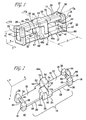
- Figure 1 is a perspective view of the clip frame assembly according to an embodiment of the present invention;
- Figure 2 is a perspective view of a portion of the frame assembly shown in Figure 1;
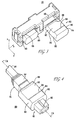
- Figure 3 is a perspective view of the clip frame assembly of Figure 1 showing portions of connectors relative to the frame assembly; and
- Figure 4 is a diagrammatic view of connector with which the clip frame assembly of Figure 1 may be employed.
-
- A
clip frame assembly 10 is shown in Figure 1.Assembly 10 preferably includes a pair of opposing first andsecond frame members 12 and 12', which are shown as identical parts such that a single mold (not shown) may be employed to form each offrame portions 12 and 12'. As explained more fully below, the identical parts are formed such that inverting (that is, re-orienting or rotating the part along a y-axis) thefirst frame member 12 relative to the second frame member 12' enables mating portions on theframe members 12 and 12' to engage or mate. - Because second frame 12' preferably is identical to
first frame 12,first frame 12 is described below, and the description of second frame 12' is generally omitted. Corresponding parts or portions of second frame 12', however, are explicitly referred to where beneficial for the understanding of the structure or function of the present invention. Where corresponding parts of frame 12' are referred to, a prime designation after the reference numeral is employed. - Preferably,
frame 12 is formed of a single, unitary part, although the present invention encompasses other configurations. Preferably,frame 12 is formed of plastic by injection molding or like conventional process.Frame 12 includes a frametransverse portion 14,frame side portion 16, andframe column assembly 18.. Frametransverse portion 14 has a longitudinal axis TA that is perpendicular to a longitudinal axis CA of a connector, as described more fully below. Frametransverse portion 14 has awide portion 24, where the width is measured along connector longitudinal axis CA. The width ofwide portion 24 may be chosen to enable the components ofcolumn assembly 18 to be suitably formed. - Relative to
wide surface 24, anundercut portion 26 is formed on at least one side oftransverse portion 14, and preferably on each, opposing side oftransverse portion 14. Undercut portion has a width that is less than the width ofwide portion 24. Thus, anundercut surface 28 is formed on a first face oftransverse portion 14 andundercut surface 30 if formed on an opposing second face oftransverse portion 14. Frametransverse portion 14 also forms aninboard contact surface 32 within the inner edges ofundercut contact surfaces - Each
frame side portion 16 extends substantially perpendicular fromtransverse portions 14 proximate ends thereof.Side portions 16 may each have a width that is greater than that of undercut 26, thereby forming ashoulder 36 therebetween. As explained more fully below, the width ofside portions 16 may be chosen to provide sufficient structure to enable the components oflatch assemblies 20 to be formed therein. Eachside portion 16 terminates, in the z direction, at amating surface 38, as best shown in Figure 1. An inboard portion ofside portion 16 forms a side portioninboard contact surface 40 which preferably is in communication with transverseportion contact surface 32. - Each
side portion 16 preferably includes a portion of thelatch assembly 20. In this regard,frame 14 has aleft side portion 16 and aright side portion 16, as oriented in Figures 1 and 2.Left side portion 16 has a cut-out that forms alanding 42. As best shown in Figure 2,landing 42 has a slopedunderside 44.Right side portion 16 includes alatch member 60 that extends downward below transverse portion contactinboard surface 32. Latchmember 60 includes an inwardly projecting hook orlip 62 with a sloped leading edgeopposite lip 62. Latchmember 60 is preferably integrally formed withframe portion 12, and may also be formed of additional pieces or comprise any other latch configuration familiar to persons skilled in the art suitable for securingframe portions 12 and 12' together. - The present disclosure employs latches, such as latch assemblies 20, that secure or hold frame portions together. The present invention is not limited to the particular latching or holding structure shown in the Figures, but rather also encompasses other means for securing or holding, including other latch assemblies (which will be apparent to persons familiar with connector technology), interference or friction fit between a protruding portion on one part that is received in a corresponding part, a continuous sleeve that encompasses both opposing parts, key interlocks (such that twisting or sliding one part relative to a corresponding part secures the parts together), and other holding or securing structure that will be apparent to persons familiar with connector technology.
-
Column assembly 18 extends between opposing frametransverse portions 14 and 14' and is formed between the left andright side portions 16. A pair ofcolumn members inboard contact surface 32 offrame member 14.Column members opposing column members 48a' and 48b' on opposing frame member 12'. Further, the present invention encompasses an interference fit, light or intermittent contact, and/or a gap betweencolumn members members 48a', 48b'.Frame members - Preferably, each
post distal surface 50 that is substantially flat. Also, eachpost interior mating surfaces 52 on the inward-facing side faces thereof. Another inward-facing side face of each ofcolumn members column contact surface 56. The fourth side ofcolumn members interior mating surfaces 52 and distal surface 50) are chamfered to enhance assembly. - Figure 4 illustrates a
connector 80 that may be employed withclip assembly 10.Connector 80, as shown in the Figures, preferably is a conventional MT fiber optic connector (including MTP and MPO styles, and the like), and includes acable 96 and astrain relief apparatus 94 attached to a back end thereof.Connector 80 includes abody 81 that extends through asleeve 82.Body 81 houses the fiber optic components (not shown) and includes a key 84 disposed on an upper side thereof.Connector 80 defines connector longitudinal axis CA. -
Sleeve 82 includes front and rear shoulder orlip Lips corresponding contact portions 28 and/or 30 ofclip assembly 10. Thus,clip assembly 10 may be employed with a connector that has an angled inward facing portion, as best shown in Figure 3, with a connector having a face that is parallel to the z axis, or with any other configuration. - A
contact surface 90 is disposed betweenlips sleeve contact surface 90 is substantially planar, and the present invention also encompasses nonplanar contact surfaces. Preferably, both the top side and bottom side ofsleeve 82 includes thelip contact surface 90 configuration. Between its top and bottom,sleeve 82 has a pair of opposing outwardly bulging orconvex sides 92. Thus, the bulge on eachside 92 ofsleeve 82 preferably defines a distal contact line of contact orpoint 93 at the outermost portion of thesides 92. - The assembled
clip frame assembly 10, as shown in Figure 1, includesframe members 12 and 12' that are latched together by latches 20. The left and right mating surfaces 38 offirst frame member 12 rest on, or are in contact or close proximity with, opposing, respective left and right mating surfaces 38' of second frame member 12'. Similarly, columndistal surfaces 50 rest on, or are in contact or close proximity with, the mating inboard contact surface 32' of opposing frame member 12'. Likewise, column distal surfaces 50' of second frame 12' rest on, or are in contact or close proximity with, the matinginboard contact surface 32 of opposingfirst frame member 12. - The
reference numeral 41 refers to a combination of adjacent portions of side portionfirst contact surface 40 and second contact surface 40'. Thus, the overall left side inboard contact surface 41 (not shown in the Figures) includes the left portion of both first and second side contact surfaces 40 and 40'. Likewise, the overall right sideinboard contact surface 41 includes the right portion of both the first and second side contact surfaces 40 and 40'. In the assembled configuration,first latch member 60 fastens the right portion ofclip assembly 10 together by engaging second landing 42' (not shown in the Figures). Likewise, second latch member 60' fastens the left portion ofclip assembly 10 together by engagingsecond landing 42. -
First column members second column members 48a' and 48b' to form a box-like structure. Thus,first column members column 18, andsecond column members 48a' and 48b' are opposed at the pair of opposite corners that are adjacent to those offirst members first column members second column members 48a' and 48b'. The chamfer surfaces 54 aid engagement or assembly ofcolumn members - The
reference numeral 57 refers to a combination of adjacent portions of column memberfirst contact surface 56 and second contact surface 56'. In this regard, a left portion ofcontact surface 57 is formed by the contact surface portions ofcolumn members 48a' and 48b. Likewise, a right portion ofcontact surface 57 is formed by the contact surface portions ofcolumn members - The assembled
clip frame assembly 10, as shown in Figure 1, defines a pair of through-apertures 22. A left one ofapertures 22 is bounded on its top and bottom by left portions of the first and second inboard contact surfaces 32 and 32' of first and secondtransverse frame members 14 and 14'. Likewise, a right one ofapertures 22 bounded on its top and bottom by right portions of the first and second inboard contact surfaces 32 and 32' of first and secondtransverse frame members 14 and 14'. The left and right portions of the inboard contact surfaces 32 and 32' are separated bycolumn assembly 18.Apertures 22 are bounded on their outer sides by left and right inboard contact surfaces 41.Apertures 22 are bounded on their inner sides by left and right column contact surfaces 57. - Each one of
apertures 22 define a centerline that is parallel with connector longitudinal centerline CA. As best shown in Figure 1, the left and right apertures may be spaced apart by a predetermined center-to-center distance D. For example, for conventional MPO or MTP connectors, an aperture spacing D of 20 mm may be employed. The present invention is not limited to any particular dimensions, and thus the dimensional information disclosed herein is for illustration purposes only. - To assemble the first and
second frame members 12 and 12' with a pair of connectors, such as MTfiber optic connector 80,first frame member 12 may be inverted relative to second frame member 12' such thatfirst column members second column members 48a' and 48b', and such that first andsecond latch members 60 and 60' engage with corresponding second andfirst landings 42' and 42 at opposite ends ofclip assembly 10. Prior to final positioning or latching first andsecond frame members 12 and 12' together, aconnector 80 is inserted into each one ofapertures 22. - In this regard, a
sleeve 82 of afirst connector 80 and asleeve 82 of anotherconnector 80 may be loosely inserted or aligned in the left andright apertures 22, respectively, of one or bothframe members 12 and 12'.Frame members 12 and 12' may be brought together such that latch sloped surfaces 64 and 64' contact thesloped undersides 44' and 44, respectively, to urgedlatch members 60 and 60' outwardly untillip 62 and 62' can engagelandings 42' and 42, respectively. Preferably,latch members 20 and 20' are resilient. Thus,frame members 12 and 12' may be coupled together and secured together by latches 20. Figure 3 illustrates a latched configuration, including aconnector 80 coupled toclip assembly 10 at the left side of Figure 3. Components of the body of theconnector 80 are omitted from Figure 3 for clarity. - In such a latched position, inboard contact surfaces 32 of
transverse frame member 14 contacts sleeve contact surface 90 (and inboard contact surface 32' contactssleeve contact surface 90 disposed on the underside of sleeve 82) to limit movement of theconnector 80 vertically (that is, in the z direction), inboard contact surfaces 41 offrame side portions 16 and/or 16' contact theside contact portions 93 ofconnector 80 to limit movement of theconnector 80 transversely or laterally (that is, in a direction parallel to the x-axis or the TA axis), and undercutcontact portions front lips connector 80 along a longitudinal axis of the connector (that is, parallel to the y-axis, or along the CA axis). -
Connector 80 is restrained from movement relative to clipassembly 10 along each direction of three axes. Such a configuration is beneficial, for example, for spacing the pair ofconnectors 80 apart by a predetermined distance. Thus, the transverse dimension (that is, along the x-axis) ofcolumn 18 may be chosen to provide a predetermined centerline distance between theconnectors 80, which may be useful for mating with like-spaced mating connectors (such as receptacles) or for other spacing considerations. Further,clip assembly 10 preferably is not part of a fixed chassis, and thus is capable of floating relative to related equipment components so as to enhance handling of the pair ofconnectors 80.Clip 10 and thesleeves 82 of a pair ofconnectors 80 disposed inapertures 22 may be moved together relative to the body ofconnectors 80, thereby simultaneously actuation the internal spring components of bothconnectors 80. -
Sleeves 82 preferably include the contact surfaces 86, 88, and 90 on both their top and bottom portions, and thus may be inverted relative to clip 10. Thus, connectors may be oriented such that bothkeys 84 are pointing up, both keys are pointing down, a combination in which one key (either the left or the right) is pointing up and the other is pointing down. Further, the present invention encompasses a configuration in which a pair ofconnectors 80 are arranged one on top of the another (not shown), rather than side by side as shown in the Figures. For such a configuration, a twist boot may be employed. - The present invention encompasses further variations, and is not limited to the particular embodiment shown herein. For example, the present invention encompasses a clip assembly that forms more than two
apertures 22 such that more than twoconnectors 80 may be secured. In this regard, more than one column assembly may be employed. Any number of apertures may be formed. The terms "top," "bottom," "left," "right," and the like, are provided for convenience of description, and it is clear that such terms should not be construed as absolute, limited to the features of the particular embodiment described herein.
Claims (13)
- A floating clip frame assembly for retaining at least a pair of connectors (80), the frame assembly (12, 12') including inboard contact surfaces (32) and a pair of opposing front and rear face contact surfaces, the front and rear face contact surfaces restricting movement of the connectors in a direction along a connector longitudinal axis, the inboard contact surfaces restricting movement of the connectors in a plane that is perpendicular to the connector longitudinal axis, characterized in that the frame assembly (12, 12') being formed by a discrete pair of opposing and inter-latching frame members, said pair of opposing frame members is composed by hermaphroditic parts (12,12'), wherein rotating the first part (12) relative to the second part (12') enables mating portions of the parts to engage.
- The floating clip frame assembly of claim 1 wherein each one of the frame members (12, 12') include an undercut portion (26) formed thereon, the undercut portions (26) forming the front and rear contact surfaces (32).
- A floating clip frame assembly according to one of the preceding claims comprising:whereby the undercut contact surface limits movement of a connector (80) along a longitudinal axis of the connector (80), the frame inboard contact surface (90) limits vertical movement of the connector, and the column contact surface and the side contact surface limit transverse movement of the connector (80).a pair of opposing sides disposed proximate ends of the frames (12,12'), each one of the opposing sides including a side contact surface (16);a column (18) extending inwardly from the frames (12, 12'), the column (18) including a pair of opposing column contact surfaces (48a, 48b);a securing means (20) for holding the opposing frames (12, 12') together;said frames (12, 12'), sides (14) and column (18) forming at least a pair of through apertures for receiving the connectors (80);an undercut portion (26) formed at least partly on at least one of the frames (14), the undercut portion (26) including opposing undercut contact surfaces (90) adapted for contacting a lip portion (86, 88) of the connector (80),
- A floating clip frame assembly of claim 3, wherein the pair of opposing transverse frames is a pair of frame portions (12, 12');
the pair of opposing side frame portions disposed proximate ends of the transverse frame portions (14);
a column (18) extending inwardly from the transverse frame portions (14), the column (18) including a pair of opposing column inboard contact surfaces;
the securing means is a latch assembly;
said transverse frame portions (14), side frame portions (12, 12'), and column (18) forming at least a pair of through apertures for receiving the connectors (80);
an undercut portion (26) formed at least partly on at least one of the transverse frame portions (14), whereby the transverse frame portion inboard contact surface limits vertical movement of the connector (80). - The floating clip frame assembly of claim 3 or 4, wherein the transverse frame inboard contact surfaces, side frame inboard contact surfaces (32), and the column inboard contact surfaces define the through apertures.
- The floating clip frame assembly of claim 3 or 4, wherein the assembly for securing (20) includes a latch member (20) and a landing (42), the latch member (20) extending from a first one of the transverse frame portions (14), the landing (42) being formed on a second one of the transverse frame portions (14'), the latch (20) including a protruding lip (62) that engages the landing (42) to secure the first and second transverse frame portions (14, 14') together.
- The floating clip frame assembly of claim 3 or 4, wherein a first one of the transverse frame portions (14, 14'), first portions of the side frame portions (16), and first portions of the column (18) are formed in a unitary first frame member (12).
- The floating clip frame assembly of claim 7, wherein a second one of the transverse frame portions (14, 14'), second portions side frame portions (16), and second portions of the column (18) are formed in a unitary second frame member (12').
- The floating clip frame assembly of claim 1, wherein the assembly (10) includes first and second latch members (20) and first and second landings (42), the first latch member (20) extending from an end of first transverse frame portion (12), the first landing (42) being formed on an opposing end of the first transverse frame portion (14), the second latch member (20') extending from an end of second transverse frame portion (14'), the second landing (42') being formed on an opposing end of the second transverse frame portion (14'), the first latch (20) engaging the first landing (42) and the second latch (20') engaging the second landing (42') to secure the first and second frame (12, 12') members together.
- The floating clip frame assembly of claim 1, wherein the column (18) is formed by a first column member (48a) and a second column member (48b), the first column member (48a) extending from the first frame member (12), the second column member (48b) extending from the second column member (12').
- The floating clip assembly of claim 10 wherein the first column member (48a) extends to the inboard contact surface (32') of the second transverse frame member (14').
- The floating clip assembly of claim 11 wherein the second column member (48b) extends to the inboard contact surface (32) of the first transverse frame member (14).
- The floating clip assembly of claim 1 wherein each one of the first and second side frame portions including mating surfaces, the mating surfaces of the first side frame portions contacting the mating surfaces of the second side frame portions.
Applications Claiming Priority (2)
| Application Number | Priority Date | Filing Date | Title |
|---|---|---|---|
| US44717 | 1993-04-12 | ||
| US10/044,717 US6793400B2 (en) | 2002-01-11 | 2002-01-11 | Floating connector clip |
Publications (2)
| Publication Number | Publication Date |
|---|---|
| EP1329992A1 EP1329992A1 (en) | 2003-07-23 |
| EP1329992B1 true EP1329992B1 (en) | 2005-04-13 |
Family
ID=21933937
Family Applications (1)
| Application Number | Title | Priority Date | Filing Date |
|---|---|---|---|
| EP03000525A Expired - Lifetime EP1329992B1 (en) | 2002-01-11 | 2003-01-09 | Floating connector clip |
Country Status (6)
| Country | Link |
|---|---|
| US (1) | US6793400B2 (en) |
| EP (1) | EP1329992B1 (en) |
| JP (1) | JP2003241018A (en) |
| CN (1) | CN1261784C (en) |
| CA (1) | CA2415996A1 (en) |
| DE (1) | DE60300481T2 (en) |
Families Citing this family (10)
| Publication number | Priority date | Publication date | Assignee | Title |
|---|---|---|---|---|
| JP4330502B2 (en) * | 2004-08-11 | 2009-09-16 | 三洋電機株式会社 | Floating connector |
| WO2007128152A2 (en) * | 2006-05-08 | 2007-11-15 | Multi-Holding Ag | Plug connector |
| US9720183B2 (en) | 2009-08-24 | 2017-08-01 | Panduit Corp. | Fiber optic adapter with enhanced alignment |
| CN103326167B (en) * | 2012-03-21 | 2016-01-13 | 东莞莫仕连接器有限公司 | Electric connector combination and wire and cable connector |
| EP3635822A4 (en) | 2017-06-07 | 2021-03-10 | Samtec, Inc. | Transceiver assembly array with fixed heatsink and floating transceivers |
| DE102018203628A1 (en) * | 2018-03-09 | 2019-09-12 | Te Connectivity Germany Gmbh | Electrical plug with elastic pressure elements |
| CN110611188B (en) * | 2018-06-15 | 2022-01-14 | 神讯电脑(昆山)有限公司 | Floating type connecting module and floating type butt joint device with same |
| CN109573050B (en) * | 2018-11-22 | 2022-03-04 | 中航华东光电有限公司 | Anti-separation limiting mechanism and anti-separation limiting device |
| CN109484920A (en) * | 2018-11-30 | 2019-03-19 | 深圳市维控达科技有限公司 | Structure for arranging wires and line sorting device |
| CN111952764B (en) * | 2020-06-22 | 2022-04-22 | 中航光电科技股份有限公司 | Connector and connector assembly |
Family Cites Families (19)
| Publication number | Priority date | Publication date | Assignee | Title |
|---|---|---|---|---|
| US3848956A (en) | 1972-03-08 | 1974-11-19 | Fargo Mfg Co Inc | Self-sealing underground tap connector |
| US4131257A (en) | 1977-11-14 | 1978-12-26 | Eby Company | Stacking cable clamp |
| US5123071A (en) * | 1990-03-09 | 1992-06-16 | Amp Incorporated | Overconnector assembly for a pair of push-pull coupling type optical fiber connectors |
| US5138680A (en) | 1991-04-17 | 1992-08-11 | Amp Incorporated | Optical fiber connector with elastomeric centering and floating alignment feature |
| US5325454A (en) * | 1992-11-13 | 1994-06-28 | International Business Machines, Corporation | Fiber optic connector housing |
| US5343547A (en) * | 1993-05-04 | 1994-08-30 | Palecek Vincent J | Overconnector assembly |
| US5398295A (en) * | 1993-09-08 | 1995-03-14 | Chang; Peter C. | Duplex clip for optical fiber connector assembly |
| US5553180A (en) * | 1995-01-17 | 1996-09-03 | Molex Incorporated | Adapter assembly for fiber optic connectors |
| NL1003149C2 (en) | 1996-05-17 | 1997-11-18 | Framatome Connectors Belgium | Backpanel connector. |
| US5931688A (en) | 1996-09-16 | 1999-08-03 | The Whitaker Company | Self docketing electrical connector assembly |
| JP3761275B2 (en) * | 1997-02-07 | 2006-03-29 | スリーエム カンパニー | Optical connector support member and optical connector assembly including the support member |
| US6027360A (en) | 1998-06-10 | 2000-02-22 | Yazaki Corporation | Junction block bracket for floating connector attachment |
| US6033247A (en) | 1998-06-24 | 2000-03-07 | Yazaki Corporation | Axially adjustable connector |
| US6030242A (en) | 1998-08-21 | 2000-02-29 | The Whitaker Corporation | Self-centering panel-mounted connector assembly |
| US6095852A (en) | 1998-12-17 | 2000-08-01 | Yazaki North America, Inc. | Connector bracket wire shield with connector retention arms |
| US6168473B1 (en) | 1999-02-02 | 2001-01-02 | Liao Sheng Hsin | Clamping structure for communication connector |
| US6139346A (en) | 1999-04-14 | 2000-10-31 | Molex Incorporated | Panel mounted connector assembly |
| US6210216B1 (en) * | 1999-11-29 | 2001-04-03 | Hon Hai Precision Ind. Co., Ltd. | Two port USB cable assembly |
| EP1156351A3 (en) * | 2000-04-27 | 2003-10-29 | Huber & Suhner Ag | Fibre optic connector system and duplex clip for such a connector system |
-
2002
- 2002-01-11 US US10/044,717 patent/US6793400B2/en not_active Expired - Fee Related
-
2003
- 2003-01-09 DE DE60300481T patent/DE60300481T2/en not_active Expired - Lifetime
- 2003-01-09 JP JP2003002850A patent/JP2003241018A/en active Pending
- 2003-01-09 EP EP03000525A patent/EP1329992B1/en not_active Expired - Lifetime
- 2003-01-09 CA CA002415996A patent/CA2415996A1/en not_active Abandoned
- 2003-01-10 CN CNB031015360A patent/CN1261784C/en not_active Expired - Fee Related
Also Published As
| Publication number | Publication date |
|---|---|
| US20030133664A1 (en) | 2003-07-17 |
| CN1432834A (en) | 2003-07-30 |
| CA2415996A1 (en) | 2003-07-11 |
| EP1329992A1 (en) | 2003-07-23 |
| DE60300481T2 (en) | 2006-02-23 |
| CN1261784C (en) | 2006-06-28 |
| JP2003241018A (en) | 2003-08-27 |
| US6793400B2 (en) | 2004-09-21 |
| DE60300481D1 (en) | 2005-05-19 |
Similar Documents
| Publication | Publication Date | Title |
|---|---|---|
| US5335301A (en) | Fiber optic connector with sliding key | |
| JP3256901B2 (en) | Optical fiber connector assembly | |
| EP0624809B1 (en) | Adapter for interconnecting optical fiber connectors or the like | |
| US5838856A (en) | Optical-fiber cable connector assembly | |
| US5121454A (en) | Optical connector | |
| US12061362B2 (en) | Housing for a fiber optic connector | |
| EP0723169B1 (en) | Adapter assembly for fiber optic connectors | |
| EP0969299A2 (en) | Optical fiber connector plug | |
| US7621676B2 (en) | Optical connector | |
| US7963704B2 (en) | Hermaphroditic fibre optical connector system | |
| EP1329992B1 (en) | Floating connector clip | |
| GB2261742A (en) | Lockable plug and socket optic fibre connector having slidable release means | |
| US11237339B2 (en) | Secure MT ferrule latching with MPO adapter | |
| EP0848267B1 (en) | Optical fiber connector assembly | |
| EP0938006A1 (en) | Structures for optical semiconductor module, optical connector, and shape adapting optical connector | |
| EP0015657B1 (en) | Optical fibre connector | |
| EP0996011B1 (en) | Duplex fiber optic connector system and method of fabrication | |
| IL150102A0 (en) | Hermaphroditic connector systems | |
| CN100443938C (en) | Optical connector | |
| WO2003021321A3 (en) | Optical connector ferrule designed to minimize manufacturing imperfections and mating misalignments by incorporating exact constraint principles | |
| JP3654052B2 (en) | Optical receptacle | |
| US5429525A (en) | Connector assembly | |
| EP1020745A2 (en) | An MT RJ compatible fiber optic connector having a substantially cylindrical ferrule | |
| JPS58200203A (en) | Optical connector | |
| US6893161B2 (en) | Optical connector device |
Legal Events
| Date | Code | Title | Description |
|---|---|---|---|
| PUAI | Public reference made under article 153(3) epc to a published international application that has entered the european phase |
Free format text: ORIGINAL CODE: 0009012 |
|
| AK | Designated contracting states |
Designated state(s): AT BE BG CH CY CZ DE DK EE ES FI FR GB GR HU IE IT LI LU MC NL PT SE SI SK TR |
|
| AX | Request for extension of the european patent |
Extension state: AL LT LV MK RO |
|
| 17P | Request for examination filed |
Effective date: 20040106 |
|
| AKX | Designation fees paid |
Designated state(s): DE FR GB |
|
| 17Q | First examination report despatched |
Effective date: 20040324 |
|
| GRAP | Despatch of communication of intention to grant a patent |
Free format text: ORIGINAL CODE: EPIDOSNIGR1 |
|
| GRAS | Grant fee paid |
Free format text: ORIGINAL CODE: EPIDOSNIGR3 |
|
| GRAA | (expected) grant |
Free format text: ORIGINAL CODE: 0009210 |
|
| RAP1 | Party data changed (applicant data changed or rights of an application transferred) |
Owner name: FCI |
|
| AK | Designated contracting states |
Kind code of ref document: B1 Designated state(s): DE FR GB |
|
| REG | Reference to a national code |
Ref country code: GB Ref legal event code: FG4D |
|
| REG | Reference to a national code |
Ref country code: IE Ref legal event code: FG4D |
|
| REF | Corresponds to: |
Ref document number: 60300481 Country of ref document: DE Date of ref document: 20050519 Kind code of ref document: P |
|
| ET | Fr: translation filed | ||
| PLBE | No opposition filed within time limit |
Free format text: ORIGINAL CODE: 0009261 |
|
| STAA | Information on the status of an ep patent application or granted ep patent |
Free format text: STATUS: NO OPPOSITION FILED WITHIN TIME LIMIT |
|
| 26N | No opposition filed |
Effective date: 20060116 |
|
| PGFP | Annual fee paid to national office [announced via postgrant information from national office to epo] |
Ref country code: GB Payment date: 20101215 Year of fee payment: 9 |
|
| REG | Reference to a national code |
Ref country code: FR Ref legal event code: CA |
|
| PGFP | Annual fee paid to national office [announced via postgrant information from national office to epo] |
Ref country code: FR Payment date: 20120111 Year of fee payment: 10 |
|
| PGFP | Annual fee paid to national office [announced via postgrant information from national office to epo] |
Ref country code: DE Payment date: 20120131 Year of fee payment: 10 |
|
| REG | Reference to a national code |
Ref country code: DE Ref legal event code: R081 Ref document number: 60300481 Country of ref document: DE Owner name: FCI, FR Free format text: FORMER OWNER: FCI, VERSAILLES, FR Effective date: 20120419 Ref country code: DE Ref legal event code: R082 Ref document number: 60300481 Country of ref document: DE Representative=s name: BEETZ & PARTNER PATENT- UND RECHTSANWAELTE, DE Effective date: 20120419 |
|
| GBPC | Gb: european patent ceased through non-payment of renewal fee |
Effective date: 20130109 |
|
| REG | Reference to a national code |
Ref country code: FR Ref legal event code: ST Effective date: 20130930 |
|
| PG25 | Lapsed in a contracting state [announced via postgrant information from national office to epo] |
Ref country code: DE Free format text: LAPSE BECAUSE OF NON-PAYMENT OF DUE FEES Effective date: 20130801 |
|
| REG | Reference to a national code |
Ref country code: DE Ref legal event code: R119 Ref document number: 60300481 Country of ref document: DE Effective date: 20130801 |
|
| PG25 | Lapsed in a contracting state [announced via postgrant information from national office to epo] |
Ref country code: GB Free format text: LAPSE BECAUSE OF NON-PAYMENT OF DUE FEES Effective date: 20130109 Ref country code: FR Free format text: LAPSE BECAUSE OF NON-PAYMENT OF DUE FEES Effective date: 20130131 |