CN1261784C - Floating connector clamp - Google Patents
Floating connector clamp Download PDFInfo
- Publication number
- CN1261784C CN1261784C CNB031015360A CN03101536A CN1261784C CN 1261784 C CN1261784 C CN 1261784C CN B031015360 A CNB031015360 A CN B031015360A CN 03101536 A CN03101536 A CN 03101536A CN 1261784 C CN1261784 C CN 1261784C
- Authority
- CN
- China
- Prior art keywords
- framework
- opposed
- pair
- contact
- connector
- Prior art date
- Legal status (The legal status is an assumption and is not a legal conclusion. Google has not performed a legal analysis and makes no representation as to the accuracy of the status listed.)
- Expired - Fee Related
Links
Images

Classifications
-
- H—ELECTRICITY
- H01—ELECTRIC ELEMENTS
- H01R—ELECTRICALLY-CONDUCTIVE CONNECTIONS; STRUCTURAL ASSOCIATIONS OF A PLURALITY OF MUTUALLY-INSULATED ELECTRICAL CONNECTING ELEMENTS; COUPLING DEVICES; CURRENT COLLECTORS
- H01R13/00—Details of coupling devices of the kinds covered by groups H01R12/70 or H01R24/00 - H01R33/00
- H01R13/62—Means for facilitating engagement or disengagement of coupling parts or for holding them in engagement
- H01R13/629—Additional means for facilitating engagement or disengagement of coupling parts, e.g. aligning or guiding means, levers, gas pressure electrical locking indicators, manufacturing tolerances
- H01R13/631—Additional means for facilitating engagement or disengagement of coupling parts, e.g. aligning or guiding means, levers, gas pressure electrical locking indicators, manufacturing tolerances for engagement only
- H01R13/6315—Additional means for facilitating engagement or disengagement of coupling parts, e.g. aligning or guiding means, levers, gas pressure electrical locking indicators, manufacturing tolerances for engagement only allowing relative movement between coupling parts, e.g. floating connection
-
- G—PHYSICS
- G02—OPTICS
- G02B—OPTICAL ELEMENTS, SYSTEMS OR APPARATUS
- G02B6/00—Light guides; Structural details of arrangements comprising light guides and other optical elements, e.g. couplings
- G02B6/24—Coupling light guides
- G02B6/36—Mechanical coupling means
- G02B6/38—Mechanical coupling means having fibre to fibre mating means
- G02B6/3807—Dismountable connectors, i.e. comprising plugs
- G02B6/3873—Connectors using guide surfaces for aligning ferrule ends, e.g. tubes, sleeves, V-grooves, rods, pins, balls
- G02B6/3874—Connectors using guide surfaces for aligning ferrule ends, e.g. tubes, sleeves, V-grooves, rods, pins, balls using tubes, sleeves to align ferrules
- G02B6/3878—Connectors using guide surfaces for aligning ferrule ends, e.g. tubes, sleeves, V-grooves, rods, pins, balls using tubes, sleeves to align ferrules comprising a plurality of ferrules, branching and break-out means
- G02B6/3879—Linking of individual connector plugs to an overconnector, e.g. using clamps, clips, common housings comprising several individual connector plugs
-
- G—PHYSICS
- G02—OPTICS
- G02B—OPTICAL ELEMENTS, SYSTEMS OR APPARATUS
- G02B6/00—Light guides; Structural details of arrangements comprising light guides and other optical elements, e.g. couplings
- G02B6/24—Coupling light guides
- G02B6/36—Mechanical coupling means
- G02B6/38—Mechanical coupling means having fibre to fibre mating means
- G02B6/3807—Dismountable connectors, i.e. comprising plugs
- G02B6/3887—Anchoring optical cables to connector housings, e.g. strain relief features
Landscapes
- Physics & Mathematics (AREA)
- General Physics & Mathematics (AREA)
- Optics & Photonics (AREA)
- Connector Housings Or Holding Contact Members (AREA)
- Mutual Connection Of Rods And Tubes (AREA)
- Mechanical Coupling Of Light Guides (AREA)
- Clamps And Clips (AREA)
Abstract
A clip assembly for holding a connector includes a pair of opposing frames that are held together by latches. Apertures formed in the clip assembly restrain movement of the connector along three axes.
Description
Technical field
The present invention relates to connecting element, particularly relate to the framework that is used for the joints of optical fibre.
Background technology
Fiber optic cables and connector assembly are known for everyone.A kind of joints of optical fibre of specific type are MT (but mechanical type conversion) types, such as MTP or MPO type.The MT type connector of being used widely as the multi-fibre connector generally has one and connects body and a sleeve.The connector sleeve can slide on the connection body, drives the blocking mechanism that connects in the body.Sleeve generally has a pair of opposed edge or flange on following two surfaces thereon.
MT type connector also as many other general connectors, generally need not external force the optical fiber that wherein connects is alignd effectively.In any case the external force that puts on connector may produce disadvantageous interference to the alignment of the optical fiber that wherein connects.
Usually exist demand to the element of the concatenation ability that strengthens fiber optic component and function.
Summary of the invention
Provide a kind of and can clamp the clip of pair of connectors at least.This clip can be handled by the connector that clip clamped, and makes it and can be fixed, and also can be released, and constitutes one group with the connector that is cooperated.
Be used for clamping at least the unsteady clip frame assembly of pair of connectors can have a frame assembly that inboard surface in contact and a pair of opposed front-back surface in contact are arranged.Front-back surface in contact restriction connector moving along connector longitudinal axis direction.The motion of inboard surface in contact restriction connector on the plane vertical with the connector longitudinal axis.Can use the groove surfaces on the front and rear part of framework.
Frame assembly can be by the discrete a pair of opposed first and second interlocking frame parts, or otherwise clamp mutually or the frame parts that is clamped together forms.Frame parts can be made first frame parts and second frame parts are of similar shape.Like this, first frame parts and second frame parts are made with regard to available same mould.
Description of drawings
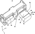
Fig. 1 is the skeleton view by the clip frame assembly of one embodiment of the present invention;
Fig. 2 is the skeleton view of a framework of frame assembly shown in Figure 1;
Fig. 3 is the skeleton view of clip frame assembly shown in Figure 1, and the connector part relevant with this frame assembly arranged shown in it; And
Fig. 4 is the synoptic diagram of the connector that can use in clip frame assembly shown in Figure 1.
Embodiment
Because second framework 12 ' preferably identical with first framework 12, below only first framework 12 is illustrated, and to second framework 12 ' explanation generally omitted.Yet, contrast second framework 12 ' parts or part, help understanding structure of the present invention or function significantly.This with second framework 12 ' relevant the also having of corresponding component, name first after using reference marker.
Though the present invention also comprises other structure, preferably framework 12 is that parts by single integral body are constituted.Preferably, framework 12 usefulness injection mouldings or similar traditional handicraft are made with plastics.Framework 12 includes framework lateral part 14, frame end head part 16, and upright of frame assembly 18.There is a longitudinal axis TA perpendicular to the longitudinal axis CA of connector framework lateral part 14, will more at large be illustrated below.There is a wide part 24 framework lateral part 14, and its width is measured along the longitudinal axis CA of connector herein.The width of wide part 24 can be selected like this, with the suitable element that forms columns assemblies 18.
Surperficial 24 with respect to wide, on a side of lateral part 14, make a groove part 26 at least, preferably 14 opposed each side are all made groove part in the lateral part.The width of groove part is less than the width of wide part 24.Like this, 14 first forms groove surfaces 28 in the lateral part, if opposed second formation groove surfaces of 14 is exactly groove surfaces 30 in the lateral part.The lateral part 14 of framework also forms an inboard surface in contact 32 within the inward flange of groove surface in contact 28 and 30.
Each frame end head part 16 can approximately 14 end substantially perpendicularly extends from the lateral part.End portion 16 can have the width bigger than groove part 26 respectively, thereby forms convex shoulder 36 betwixt.Elaborate more as following, the width of end portion 16 can be selected like this, so that enough structures to be provided, makes it possible to form therein the element of latch assembly 20.Each end portion 16 ends at matching surface 38 along the Z direction, as shown in Figure 1.The inside part of end portion 16 forms the inboard surface in contact 40 in termination, and the preferred and lateral part surface in contact 32 in this surface 40 links.
Each end portion 16 preferably all contains the part of latch assembly 20.About this point, framework 14 has left end head part 16 and right-hand member head part 16, and is directed as depicted in figs. 1 and 2.Left end head part 16 has the otch that is forming lock place 42.As shown in Figure 2, lock place 42 and have a downside 44 that tilts.Right-hand member head part 16 has the latch member 60 that extends downwardly under the inboard surface in contact 32 in lateral part.Latch member 60 has to projecting inward hook or flange 62, with the flange 62 relative guide edges that inclination is arranged.Preferred and the frame part 12 of latch member 60 is made of one, but also can make annex or those skilled in the art were familiar with is suitable for any bolt structure framework 12 and 12 ' be locked together.
Disclosed herein be to use resemble latch assembly 20 such can be frame part locking or the lock bolt that is clamped together.The present invention is not limited to specific locking or the clamp structure shown in the figure, but also can have the device of other lockings or clamping, the latch assembly (is conspicuous to the people who is familiar with the connector technology) that comprises other, interfere or friction is suitable between the projection on the parts in being contained in corresponding component, continuous sleeve with two opposed parts, key formula interlock (make parts with respect to corresponding component twisting motion or slip and these parts are locked together), and other conspicuous clamping or locking mechanisms concerning the people who is familiar with the connector technology.
Columns assemblies 18 opposed framework lateral part 14 and 14 ' between extend, and be formed between the left and right sides end portion 16.A pair of pillar parts 48a and 48b extend (directed as shown in Figure 1) inboard surface in contact 32 to frame parts 14 downwards.Pillar parts 48a and 48b stagger mutually, so as to make they can with opposed frame parts 12 ' on opposed pillar parts 48a ' and 48b ' cooperate or dock.In addition, the present invention has the interference engagement between pillar parts 48a, 48b and parts 48a ', 48b ', contact slight or that be interrupted, and/or gap.Illustrated frame parts 48a and 48b are the square-section, can certainly use cylindrical or other shapes.
The end face 50 of preferred each column 48a and 48b is flat basically.Equally, each column 48a and 48b have matching surface 52 in a pair on its inside side.Another inside side of each pillar parts 48a and 48b forms column surface in contact 56.The 4th side of pillar parts 48a and 48b is outside.(it forms at interior matching surface 52 and end face 50 intersections) makes chamfering to improve assembleability at preferably a pair of inside edge 54.
Fig. 4 illustrates can be with the connector 80 of clip assembly 10 uses.Connector 80, as shown in the figure, preferably a kind of traditional MT joints of optical fibre (comprising MTP and MPO type etc.), it also comprises optical cable 96 and is connected the tension force abatement device 94 of its rear end.Connector 80 has the connection body 81 that extends through sleeve 82.Connect body 81 receiving optical fiber device (not shown) and comprise the key 84 of end disposed thereon.Connector 80 has been determined connector longitudinal axis CA.
Convex shoulder or flange 86 and 88 before and after sleeve 82 has respectively. Flange 86 and 88 can have the Any shape that can be meshed with the corresponding contact portion 28 and/or 30 of clip assembly 10.Like this, clip assembly 10 just can be with there being the connector towards interior sloping portion to use, and as shown in Figure 3, with the connector with the face that is parallel to the Z axle, or uses with the connector of any other structure.
Surface in contact 90 is between flange 86 and 88.Sleeve surface in contact 90 preferably is essentially the plane, and the present invention also can have nonplanar surface in contact.The end face of sleeve 82 and bottom surface preferably all have the structure of flange 86,88 and surface in contact 90.Between its end face and bottom surface, sleeve 82 has the projecting surface or the convex surface 92 of a pair of opposed outside protrusion.Like this, the protuberance of each side 92 of sleeve 82 preferably in the side 92 outermost partly determined the osculatory or the contact point 93 of outermost.
The clip frame assembly 10 that assembles, as shown in Figure 1, comprise the frame parts 12 and 12 that is locked together with lock bolt 20 '.The left side of first frame parts 12 lean against or contact with right matching surface 38 or very near second frame parts 12 ' an opposed corresponding left side and right matching surface 38 ' on.Similarly, column end face 50 lean against or contact or very near opposed frame parts 12 ' the inboard surface in contact 32 of cooperation ' on.Equally, second frame parts 12 ' end face 50 ' lean against or contact or very near on the inboard surface in contact 32 of the cooperation of opposed first frame parts 12.
The clip frame assembly 10 that assembles as shown in Figure 1, has been determined a pair of through hole 22.Hole 22, the left side in its top and bottom by first and second lateral frame element 14 and 14 ' the first and second inboard surface in contacts 32 and 32 ' the left lateral branch define.Equally, hole 22, the right in its top and bottom by first and second lateral frame element 14 and 14 ' first and second inner contact surfaces 32 and 32 ' right-hand component defined.Inboard surface in contact 32 and 32 ' the left side and right-hand component separated by columns assemblies 18.Each hole 22 its outside by about in connect side and touch the surface and 41 define.Hole 22 side is within it defined by left and right pillar surface in contact 57.
Each hole 22 determined one with the parallel center line of connector longitudinal centre line CA.Can clearly be seen that in Fig. 1 the hole on the left side and the right can separate each other with predetermined centre distance D.For example, for traditional MPO or MTP connector, can use the pitch of holes D of 20mm.The invention is not restricted to any specific size, dimension information therefore disclosed herein is only used for diagram.
For first and second frame parts 12 and 12 ' fit together with pair of connectors, as the MT joints of optical fibre 80, first frame parts 12 can be with respect to second frame parts 12 ' upset, so that the first pillar parts 48a and 48b stagger mutually with the second pillar parts 48a ' and 48b ' and cooperatively interact, so just can make first and second latch member 60 and 60 ' with the opposite end of clip assembly 10 corresponding second and first lock place 42 ' and 42 be meshing with each other., first and second frame parts 12 and 12 ' before locating or being locked together connector 80 is inserted among each hole 22 finally.
In this respect, the sleeve 82 of the sleeve 82 of first connector 80 and another one connector 80 can loosely insert or be arranged in one or two frame parts 12 and 12 ' a left side and right hole 22 among.Frame parts 12 and 12 ' put together, make the inclined surface 64 and 64 of lock bolt ' with the downside 44 that tilts ' and 44 be in contact with one another respectively, promote from the outside latch member 60 and 60 ', up to flange 62 and 62 ' can mesh with lock place 42 ' and 42 respectively.Preferred latch member 20 and 20 ' be resilient.Like this, frame parts 12 and 12 ' can be connected and be clamped together with lock bolt 20.Fig. 3 illustrates the structure of locking, is the connector 80 with clip assembly 10 couplings in the left side of Fig. 3.For the sake of clarity, omitted the element of connector 80 bodies among Fig. 3.
At such locked position, the inboard surface in contact 32 of lateral frame element 14 contact with sleeve surface in contact 90 (and inboard surface in contact 32 ' contact) with the sleeve surface in contact 90 that is positioned at sleeve 82 downsides, motion with restriction connector 80 vertical direction (promptly along the Z direction), frame end head part 16 and/or 16 ' inboard surface in contact 41 contact with the contacts side surfaces part 93 of connector 80, with 80 motions horizontal or side direction (i.e. edge and X-axis or the parallel direction of TA axle) of restriction connector, and groove contact portion 28 and 30 contacts with back front flange 86 and 88 respectively, with the motion of restriction connector 80 along connector longitudinal axis (promptly be parallel to Y-axis or along the CA axle).
Each sleeve 82 preferably all has surface in contact 86,88 and 90 at its top and bottom, therefore can be with respect to clip 10 upsets.Like this, connector can be placed like this, and two keys 84 are all made progress, or makes two keys all downward, or a key (left button or right button) is made progress and the downward combination of another key.In addition, the present invention also has structure (not shown) that is arranged in another top in pair of connectors 80, rather than resembles placed side by side shown in the figure.Such structure can use spirality sleeve pipe (twist boot).
The present invention also has other modification, is not limited to the specific embodiment that this paper lifts.For example, the present invention also has the clip assembly of formation more than two holes 22, so that can clamp the connector 80 more than two.At this moment, also can use more than one columns assemblies.Any amount of hole can both form.Term ' top ', ' bottom ', ' left side ', ' right side ' etc. all is for convenience, these terms should not explained utterly obviously.Can imagine many additional modification at aspects such as structure, function, materials, as for seen feature disclosed herein be familiar with connecting element the people understood.Therefore, the present invention should not be limited to the feature of the specific embodiment that this paper narrates.
Claims (14)
1. one kind is used for the clamping unsteady clip assembly of pair of connectors at least, and this unsteady clip assembly comprises:
A pair of opposed framework, each framework all have a framework surface in contact;
The a pair of opposed termination that is positioned at the framework end, each in this opposed termination all has a termination surface in contact;
From the column that framework extends internally, this column comprises a pair of opposed column surface in contact;
The clamp device that opposed framework is clamped together;
Described framework, termination and column form at least one pair of through hole that is used to hold connector;
The groove part that at least one described framework, forms at least in part, this groove part be positioned at frame assembly an outside and on the part of outside and have and be suitable for the opposed groove surface in contact that contacts with the flange portion of connector;
Wherein, described groove contact surface-limited connector moves along the connector longitudinal axis, the vertical movement of the inboard surface in contact restriction of described framework connector, and the transverse movement of described column surface in contact and termination surface in contact system connector.
2. according to the described unsteady clip frame assembly of claim 1, it is characterized in that, described clamp device comprises latch member and lock place, first framework of this latch member from described opposed framework extends, be somebody's turn to do lock and be on second framework in the described opposed framework and form, thereby lock bolt has the flange that first and second frameworks is clamped together with the engagement of lock place.
3. according to the described unsteady clip frame assembly of claim 1, it is characterized in that, in the first single frame parts, form first framework, each first of described termination and each first of described column in the described framework.
4. according to the described unsteady clip frame assembly of claim 3, it is characterized in that, in the second single frame parts, form second framework, each second portion of described end face and each second portion of described column in the described framework.
5. according to the described unsteady clip frame assembly of claim 4, it is characterized in that first frame parts and second frame parts are of similar shape.
6. according to the described unsteady clip frame assembly of claim 5, it is characterized in that first frame parts and second frame parts can be with identical mould productions.
7. according to the described unsteady clip assembly of claim 1, it is characterized in that, this assembly comprise first and second latch member and first and second the lock place, extend one end of one first lateral part of the framework of first latch member from described a pair of opposed framework, first the lock opposed end that is in described first lateral part of a framework in the described a pair of opposed framework form, extend one end of one second lateral part of another framework of second latch member from described a pair of opposed framework, second the lock opposed end that is in described second lateral part form, first lock bolt and second lock place engagement, and second lock bolt and first lock place engagement, thereby described a pair of opposed framework is clamped together.
8. according to the described unsteady clip frame assembly of claim 1, it is characterized in that, described column is made up of first pillar parts and second pillar parts, the framework of first pillar parts from described a pair of opposed framework extends, and second pillar parts another framework from described a pair of opposed framework extends.
9. according to the described unsteady clip frame assembly of claim 8, it is characterized in that described first pillar parts extends to the inboard surface in contact of framework of second lateral part of another framework in the described a pair of opposed framework.
10. according to the described unsteady clip frame assembly of claim 9, it is characterized in that described second pillar parts extends to the inboard surface in contact of framework of first lateral part of another framework in the described a pair of opposed framework.
11. according to the described unsteady clip frame assembly of claim 1, it is characterized in that, framework from described a pair of opposed framework extend each opposed termination each with another framework extension from described a pair of opposed framework contacted to opposed termination.
12. one kind is used for the clamping unsteady clip frame assembly of pair of connectors at least, this frame assembly limits a pair of connector through hole and a pair of opposed front and back surface in contact of being determined by a plurality of inboard surface in contacts, described front and back surface in contact be positioned at described frame assembly each outside and on the part of outside, and, surface in contact restriction connector moving in described front and back along connector longitudinal axis direction, described inboard surface in contact restriction connector is perpendicular to the motion in the plane of connector longitudinal axis, described frame assembly is formed by discrete frame parts a pair of opposed and interlocking, wherein, at least one frame parts in the described frame parts comprises the groove part of a front, the longitudinal size of this groove part is less than the longitudinal size of described inboard surface in contact, and described front contact surface is positioned on the groove part of this front.
13., it is characterized in that described frame parts is identical according to the described unsteady clip frame assembly of claim 12.
14., it is characterized in that described groove part forms described front and back surface in contact according to the described unsteady clip frame assembly of claim 12.
Applications Claiming Priority (2)
| Application Number | Priority Date | Filing Date | Title |
|---|---|---|---|
| US10/044,717 US6793400B2 (en) | 2002-01-11 | 2002-01-11 | Floating connector clip |
| US10/044,717 | 2002-01-11 |
Publications (2)
| Publication Number | Publication Date |
|---|---|
| CN1432834A CN1432834A (en) | 2003-07-30 |
| CN1261784C true CN1261784C (en) | 2006-06-28 |
Family
ID=21933937
Family Applications (1)
| Application Number | Title | Priority Date | Filing Date |
|---|---|---|---|
| CNB031015360A Expired - Fee Related CN1261784C (en) | 2002-01-11 | 2003-01-10 | Floating connector clamp |
Country Status (6)
| Country | Link |
|---|---|
| US (1) | US6793400B2 (en) |
| EP (1) | EP1329992B1 (en) |
| JP (1) | JP2003241018A (en) |
| CN (1) | CN1261784C (en) |
| CA (1) | CA2415996A1 (en) |
| DE (1) | DE60300481T2 (en) |
Families Citing this family (10)
| Publication number | Priority date | Publication date | Assignee | Title |
|---|---|---|---|---|
| JP4330502B2 (en) | 2004-08-11 | 2009-09-16 | 三洋電機株式会社 | Floating connector |
| CA2650823C (en) * | 2006-05-08 | 2016-02-23 | Multi-Holding Ag | Plug-type connection |
| US9720183B2 (en) | 2009-08-24 | 2017-08-01 | Panduit Corp. | Fiber optic adapter with enhanced alignment |
| CN103326167B (en) * | 2012-03-21 | 2016-01-13 | 东莞莫仕连接器有限公司 | Electric connector combination and wire and cable connector |
| MY192137A (en) | 2017-06-07 | 2022-07-29 | Samtec Inc | Transceiver assembly array with fixed heatsink and floating transceivers |
| DE102018203628A1 (en) * | 2018-03-09 | 2019-09-12 | Te Connectivity Germany Gmbh | Electrical plug with elastic pressure elements |
| CN110611188B (en) * | 2018-06-15 | 2022-01-14 | 神讯电脑(昆山)有限公司 | Floating type connecting module and floating type butt joint device with same |
| CN109573050B (en) * | 2018-11-22 | 2022-03-04 | 中航华东光电有限公司 | Anti-separation limiting mechanism and anti-separation limiting device |
| CN109484920A (en) * | 2018-11-30 | 2019-03-19 | 深圳市维控达科技有限公司 | Structure for arranging wires and line sorting device |
| CN111952764B (en) * | 2020-06-22 | 2022-04-22 | 中航光电科技股份有限公司 | Connector and connector assembly |
Family Cites Families (19)
| Publication number | Priority date | Publication date | Assignee | Title |
|---|---|---|---|---|
| US3848956A (en) | 1972-03-08 | 1974-11-19 | Fargo Mfg Co Inc | Self-sealing underground tap connector |
| US4131257A (en) | 1977-11-14 | 1978-12-26 | Eby Company | Stacking cable clamp |
| US5123071A (en) * | 1990-03-09 | 1992-06-16 | Amp Incorporated | Overconnector assembly for a pair of push-pull coupling type optical fiber connectors |
| US5138680A (en) | 1991-04-17 | 1992-08-11 | Amp Incorporated | Optical fiber connector with elastomeric centering and floating alignment feature |
| US5325454A (en) * | 1992-11-13 | 1994-06-28 | International Business Machines, Corporation | Fiber optic connector housing |
| US5343547A (en) * | 1993-05-04 | 1994-08-30 | Palecek Vincent J | Overconnector assembly |
| US5398295A (en) * | 1993-09-08 | 1995-03-14 | Chang; Peter C. | Duplex clip for optical fiber connector assembly |
| US5553180A (en) * | 1995-01-17 | 1996-09-03 | Molex Incorporated | Adapter assembly for fiber optic connectors |
| NL1003149C2 (en) | 1996-05-17 | 1997-11-18 | Framatome Connectors Belgium | Backpanel connector. |
| US5931688A (en) | 1996-09-16 | 1999-08-03 | The Whitaker Company | Self docketing electrical connector assembly |
| JP3761275B2 (en) * | 1997-02-07 | 2006-03-29 | スリーエム カンパニー | Optical connector support member and optical connector assembly including the support member |
| US6027360A (en) | 1998-06-10 | 2000-02-22 | Yazaki Corporation | Junction block bracket for floating connector attachment |
| US6033247A (en) | 1998-06-24 | 2000-03-07 | Yazaki Corporation | Axially adjustable connector |
| US6030242A (en) | 1998-08-21 | 2000-02-29 | The Whitaker Corporation | Self-centering panel-mounted connector assembly |
| US6095852A (en) | 1998-12-17 | 2000-08-01 | Yazaki North America, Inc. | Connector bracket wire shield with connector retention arms |
| US6168473B1 (en) | 1999-02-02 | 2001-01-02 | Liao Sheng Hsin | Clamping structure for communication connector |
| US6139346A (en) | 1999-04-14 | 2000-10-31 | Molex Incorporated | Panel mounted connector assembly |
| US6210216B1 (en) * | 1999-11-29 | 2001-04-03 | Hon Hai Precision Ind. Co., Ltd. | Two port USB cable assembly |
| EP1156351A3 (en) * | 2000-04-27 | 2003-10-29 | Huber & Suhner Ag | Fibre optic connector system and duplex clip for such a connector system |
-
2002
- 2002-01-11 US US10/044,717 patent/US6793400B2/en not_active Expired - Fee Related
-
2003
- 2003-01-09 JP JP2003002850A patent/JP2003241018A/en active Pending
- 2003-01-09 CA CA002415996A patent/CA2415996A1/en not_active Abandoned
- 2003-01-09 EP EP03000525A patent/EP1329992B1/en not_active Expired - Lifetime
- 2003-01-09 DE DE60300481T patent/DE60300481T2/en not_active Expired - Lifetime
- 2003-01-10 CN CNB031015360A patent/CN1261784C/en not_active Expired - Fee Related
Also Published As
| Publication number | Publication date |
|---|---|
| EP1329992B1 (en) | 2005-04-13 |
| US20030133664A1 (en) | 2003-07-17 |
| CA2415996A1 (en) | 2003-07-11 |
| US6793400B2 (en) | 2004-09-21 |
| DE60300481T2 (en) | 2006-02-23 |
| EP1329992A1 (en) | 2003-07-23 |
| DE60300481D1 (en) | 2005-05-19 |
| JP2003241018A (en) | 2003-08-27 |
| CN1432834A (en) | 2003-07-30 |
Similar Documents
| Publication | Publication Date | Title |
|---|---|---|
| CN1261784C (en) | Floating connector clamp | |
| CN1192268C (en) | Optical fiber connector | |
| CN1030856C (en) | Connecting pin | |
| CN1269271C (en) | Floating mounting for connector device | |
| CN1203342C (en) | Centring system of pairing connector | |
| DE69026472T2 (en) | Optical connector | |
| JP3505237B2 (en) | Plug holding device and duplex type optical connector using the same | |
| CN1345558A (en) | Buckle | |
| JP6900525B2 (en) | Rod holding system and method | |
| CN1258011A (en) | Connector assembly | |
| CN1100000A (en) | Block assembly | |
| CN1142268A (en) | High-density optical-fiber distribution frame | |
| CN1425144A (en) | Duplex connectors for optical fibre plug connectors | |
| DE60306185T2 (en) | FIBER OPTIC CONNECTOR MODULE | |
| US20240019641A1 (en) | Lensed fiber optic ferrule with simplified molding | |
| DE69218480T2 (en) | Optical fiber connection | |
| CN105283786B (en) | Optical fiber interconnections component | |
| CN1846160A (en) | Optical connector | |
| DE112012001644T5 (en) | Optical connector and ferrule | |
| US6364534B1 (en) | Panel mounting assembly for optical fiber connectors | |
| CN1180287C (en) | Connector | |
| US9810850B1 (en) | Fiber gripper assembly for optical connectors | |
| CN1250527A (en) | Adapters for coupling optical fiber | |
| CN1317704A (en) | Fiber glass cable sleeve | |
| CN1097967A (en) | Hasp |
Legal Events
| Date | Code | Title | Description |
|---|---|---|---|
| C06 | Publication | ||
| PB01 | Publication | ||
| C10 | Entry into substantive examination | ||
| SE01 | Entry into force of request for substantive examination | ||
| C14 | Grant of patent or utility model | ||
| GR01 | Patent grant | ||
| C56 | Change in the name or address of the patentee | ||
| CP02 | Change in the address of a patent holder |
Address after: French guyancourt Patentee after: FCI S. A. Address before: France Patentee before: FCI S. A. |
|
| CF01 | Termination of patent right due to non-payment of annual fee | ||
| CF01 | Termination of patent right due to non-payment of annual fee |
Granted publication date: 20060628 Termination date: 20130110 |