EP1329663B1 - Device for radiating light - Google Patents
Device for radiating light Download PDFInfo
- Publication number
- EP1329663B1 EP1329663B1 EP03075186A EP03075186A EP1329663B1 EP 1329663 B1 EP1329663 B1 EP 1329663B1 EP 03075186 A EP03075186 A EP 03075186A EP 03075186 A EP03075186 A EP 03075186A EP 1329663 B1 EP1329663 B1 EP 1329663B1
- Authority
- EP
- European Patent Office
- Prior art keywords
- light sources
- casing
- decoration
- frame
- foregoing
- Prior art date
- Legal status (The legal status is an assumption and is not a legal conclusion. Google has not performed a legal analysis and makes no representation as to the accuracy of the status listed.)
- Expired - Lifetime
Links
- 238000005034 decoration Methods 0.000 claims description 30
- 238000010276 construction Methods 0.000 claims description 4
- 239000003086 colorant Substances 0.000 claims description 2
- 239000002184 metal Substances 0.000 claims description 2
- 239000000725 suspension Substances 0.000 claims description 2
- 230000000694 effects Effects 0.000 description 6
- 239000007787 solid Substances 0.000 description 3
- 229910000831 Steel Inorganic materials 0.000 description 2
- 238000005265 energy consumption Methods 0.000 description 2
- 239000010959 steel Substances 0.000 description 2
- 230000000712 assembly Effects 0.000 description 1
- 238000000429 assembly Methods 0.000 description 1
- GINJFDRNADDBIN-FXQIFTODSA-N bilanafos Chemical compound OC(=O)[C@H](C)NC(=O)[C@H](C)NC(=O)[C@@H](N)CCP(C)(O)=O GINJFDRNADDBIN-FXQIFTODSA-N 0.000 description 1
- 230000008878 coupling Effects 0.000 description 1
- 238000010168 coupling process Methods 0.000 description 1
- 238000005859 coupling reaction Methods 0.000 description 1
- 230000005611 electricity Effects 0.000 description 1
- 238000004519 manufacturing process Methods 0.000 description 1
- 230000003068 static effect Effects 0.000 description 1
Images

Classifications
-
- F—MECHANICAL ENGINEERING; LIGHTING; HEATING; WEAPONS; BLASTING
- F21—LIGHTING
- F21V—FUNCTIONAL FEATURES OR DETAILS OF LIGHTING DEVICES OR SYSTEMS THEREOF; STRUCTURAL COMBINATIONS OF LIGHTING DEVICES WITH OTHER ARTICLES, NOT OTHERWISE PROVIDED FOR
- F21V21/00—Supporting, suspending, or attaching arrangements for lighting devices; Hand grips
- F21V21/008—Suspending from a cable or suspension line
-
- F—MECHANICAL ENGINEERING; LIGHTING; HEATING; WEAPONS; BLASTING
- F21—LIGHTING
- F21S—NON-PORTABLE LIGHTING DEVICES; SYSTEMS THEREOF; VEHICLE LIGHTING DEVICES SPECIALLY ADAPTED FOR VEHICLE EXTERIORS
- F21S4/00—Lighting devices or systems using a string or strip of light sources
- F21S4/20—Lighting devices or systems using a string or strip of light sources with light sources held by or within elongate supports
- F21S4/22—Lighting devices or systems using a string or strip of light sources with light sources held by or within elongate supports flexible or deformable, e.g. into a curved shape
- F21S4/26—Lighting devices or systems using a string or strip of light sources with light sources held by or within elongate supports flexible or deformable, e.g. into a curved shape of rope form, e.g. LED lighting ropes, or of tubular form
-
- F—MECHANICAL ENGINEERING; LIGHTING; HEATING; WEAPONS; BLASTING
- F21—LIGHTING
- F21S—NON-PORTABLE LIGHTING DEVICES; SYSTEMS THEREOF; VEHICLE LIGHTING DEVICES SPECIALLY ADAPTED FOR VEHICLE EXTERIORS
- F21S8/00—Lighting devices intended for fixed installation
- F21S8/03—Lighting devices intended for fixed installation of surface-mounted type
- F21S8/033—Lighting devices intended for fixed installation of surface-mounted type the surface being a wall or like vertical structure, e.g. building facade
-
- F—MECHANICAL ENGINEERING; LIGHTING; HEATING; WEAPONS; BLASTING
- F21—LIGHTING
- F21S—NON-PORTABLE LIGHTING DEVICES; SYSTEMS THEREOF; VEHICLE LIGHTING DEVICES SPECIALLY ADAPTED FOR VEHICLE EXTERIORS
- F21S8/00—Lighting devices intended for fixed installation
- F21S8/04—Lighting devices intended for fixed installation intended only for mounting on a ceiling or the like overhead structures
- F21S8/06—Lighting devices intended for fixed installation intended only for mounting on a ceiling or the like overhead structures by suspension
-
- F—MECHANICAL ENGINEERING; LIGHTING; HEATING; WEAPONS; BLASTING
- F21—LIGHTING
- F21S—NON-PORTABLE LIGHTING DEVICES; SYSTEMS THEREOF; VEHICLE LIGHTING DEVICES SPECIALLY ADAPTED FOR VEHICLE EXTERIORS
- F21S8/00—Lighting devices intended for fixed installation
- F21S8/08—Lighting devices intended for fixed installation with a standard
-
- F—MECHANICAL ENGINEERING; LIGHTING; HEATING; WEAPONS; BLASTING
- F21—LIGHTING
- F21W—INDEXING SCHEME ASSOCIATED WITH SUBCLASSES F21K, F21L, F21S and F21V, RELATING TO USES OR APPLICATIONS OF LIGHTING DEVICES OR SYSTEMS
- F21W2121/00—Use or application of lighting devices or systems for decorative purposes, not provided for in codes F21W2102/00 – F21W2107/00
-
- F—MECHANICAL ENGINEERING; LIGHTING; HEATING; WEAPONS; BLASTING
- F21—LIGHTING
- F21Y—INDEXING SCHEME ASSOCIATED WITH SUBCLASSES F21K, F21L, F21S and F21V, RELATING TO THE FORM OR THE KIND OF THE LIGHT SOURCES OR OF THE COLOUR OF THE LIGHT EMITTED
- F21Y2115/00—Light-generating elements of semiconductor light sources
- F21Y2115/10—Light-emitting diodes [LED]
Definitions
- the present invention relates to a device for radiating light in the form of long strings with light sources which realize an attractive, decorative effect.
- Devices with such a decorative effect are already known.
- due to the plurality of light sources, such devices use a great deal of energy.
- the present invention provides a device for radiating light, comprising:
- the light sources are preferably LEDs.
- the energy consumption is herby reduced.
- As a light source LEDs further have a very great robustness and a long lifespan of up to for instance 20 years.
- the devices hereby acquire a high reliability during use.
- a further advantage of the use of LEDs is that these are safer in use, for instance because the heat development is much lower.
- the use of LEDs in such devices further becomes attractive in that different colours of LED have recently become available.
- Patent publication FR 2 811063 discloses a lighting device comprising a bracket for carrying a light tube with conventional light bulbs. Switching means are located outside the light tube.
- Patent application US 4 681 687 discloses an ornamental light device with tubular light structures comprising mini-lamps for indoor decorative purposes. No switching means are disclosed in US 4 581 687.
- Patent publication DE 198 08 536 discloses a light tube with LED's embedded therein. Again, no switching means are disclosed.
- the light sources are preferably connected in groups.
- a voltage source having a higher voltage than required per light source can for instance hereby be applied.
- the light sources are positioned in the casing at a mutual distance of for instance 1-15 centimetres. Placing of light sources at such distances produces an effect of continuity to a series of light sources in such a casing.
- An above described device can have a length of up to for instance 250 metres.
- the making of large decorations illuminated using the device hereby becomes very simple, since very few connecting points are necessary.
- the device further comprises switching means for switching separate light sources or groups of light sources. Separate light sources or groups of light sources can hereby be switched on or off, whereby motion-simulating effects can for instance be achieved by means of the light sources placed in the device.
- a further aspect of the present invention provides decorations for decorative lighting of (public) spaces, comprising:
- Such a decoration has the advantage that ornamental lighting can be arranged on the decorations in very simple and/or flexible, changeable manner.
- this ornamental lighting has the same advantages as described in the foregoing.
- the frame comprises a metal construction.
- Such decorations can be used more than once owing to their solid nature.
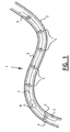
- FIG. 1 An embodiment according to the present invention (fig. 1) shows a part of a substantially tube-like decorative device 1.
- the decorative device comprises a casing 2 which is substantially tube-like.
- Two conducting wires 3,4 are arranged herein for supplying electricity. Between these electrical wires are arranged wires 7 which switch one or more LEDs (in the present case 6). Further connected herein are switching means 6 which can comprise electrical components, including for instance resistors or a processing unit.
- An object of such switching means 6 is that flashing or motion effects can be realized using the number of light sources positioned in the casing.
- the operation of such switching means can be controlled from a central control member (not shown) which forms part of the device and which can for instance be arranged at the position of the coupling of the tube to an external power source.
- a suitable pulse coding can then be applied to control the switching means, these pulses being supplied via wiring 3,4,7.
- a switching group of 6 LEDs is described and shown in the foregoing. Further assemblies of connections are for instance 12 LEDs per switching group, 18 LEDs per switching group or 36 LEDs per switching group, although any practical number can be applied depending on for instance manufacture or applied voltage. Such tubes can for instance be produced in a length of about 30m, 60m, 90m or 180 metres respectively.
- an LED for applying can for instance use 0.02 A at 120V, whereby this group has a power of 2.4 Watts.
- a tube with 360 LEDs and 20 groups uses only 48 Watts of energy.
- the above described tube-like decoration or LED tube is applied in ornaments wherein use is traditionally made of light bulbs.
- Such ornaments are for instance used for lighting public spaces. Ornaments are also used to decorate homes, wherein relatively smaller light bulbs are then applied.
- Figure 2 shows three examples of (outdoor) ornaments on which can be arranged the tube-like light decoration as described above. These examples are not however limitative for the application of the tube-like decoration. Such decorations can take a very solid form for multiple use year after year and in simple manner can obtain a different surprising or attractive appearance using the tube-like decoration.
- FIG. 2 shows three embodiments 14, 15 and 16 according to the present invention.
- Embodiment 14 shows a street-spanning decoration for fixing to a steel cable. Such decorations are often applied above for instance shopping streets during festive periods.
- Another embodiment 15 relates to a lighting decoration which is especially suitable for fixing to vertical walls. In addition to use in shopping streets, such decorations can also be applied anywhere where vertical walls are available.
- Such self-supporting constructions can be placed anywhere where posts can be placed.
- the street-spanning decoration 14 can be fixed in the usual manner between two facades, suspended on for instance a steel cable using suspension eyes.
- the decorations according to embodiments 14, 15 and 16 are very solid decorations with frames which can be used year after year as street decoration or decoration of for instance large shopping centres. Such frames have already been applied for a long time by applicant, wherein the frames are provided with large quantities of light bulbs. The energy consumption of these decorations is hereby very high.
- the use of tubes with LEDs can greatly reduce this energy use, while lighting effects can be achieved which have an attention value differing from those achieved with the known light bulbs.
Abstract
Description
- The present invention relates to a device for radiating light in the form of long strings with light sources which realize an attractive, decorative effect. Devices with such a decorative effect are already known. However, due to the plurality of light sources, such devices use a great deal of energy.
- In order to obviate this drawback, the present invention provides a device for radiating light, comprising:
- a frame with a predetermined decorative shape,
- a substantially tube-like casing, comprising:
- a relatively large number of light sources arranged in the interior of the casing,
- conducting means for connecting the light sources in electrically conducting manner, wherein the conducting means are arranged in the interior of the casing, wherein
- the casing is arranged on the frame in accordance with a predetermined shape.
- The light sources are preferably LEDs. The energy consumption is herby reduced. As a light source LEDs further have a very great robustness and a long lifespan of up to for instance 20 years. The devices hereby acquire a high reliability during use. A further advantage of the use of LEDs is that these are safer in use, for instance because the heat development is much lower. The use of LEDs in such devices further becomes attractive in that different colours of LED have recently become available.
-
Patent publication FR 2 811063 discloses a lighting device comprising a bracket for carrying a light tube with conventional light bulbs. Switching means are located outside the light tube. Patent application US 4 681 687 discloses an ornamental light device with tubular light structures comprising mini-lamps for indoor decorative purposes. No switching means are disclosed in US 4 581 687. Patent publication DE 198 08 536 discloses a light tube with LED's embedded therein. Again, no switching means are disclosed. - In addition, the light sources are preferably connected in groups. A voltage source having a higher voltage than required per light source can for instance hereby be applied.
- In a further preferred embodiment the light sources are positioned in the casing at a mutual distance of for instance 1-15 centimetres. Placing of light sources at such distances produces an effect of continuity to a series of light sources in such a casing.
- An above described device can have a length of up to for instance 250 metres. The making of large decorations illuminated using the device hereby becomes very simple, since very few connecting points are necessary.
- In a further preferred embodiment the device further comprises switching means for switching separate light sources or groups of light sources. Separate light sources or groups of light sources can hereby be switched on or off, whereby motion-simulating effects can for instance be achieved by means of the light sources placed in the device.
- In the field of street decoration with which public spaces are decorated for instance during (and/or prior to) holiday periods, decorations are known in which traditional light bulbs are applied. Such decorations have the drawback that the lighting thereof is very static, since the placing of the light bulbs is determined for instance by the fixed position of the fittings therefor.
- In order to obviate such drawbacks, a further aspect of the present invention provides decorations for decorative lighting of (public) spaces, comprising:
- a frame with a predetermined decorative shape,
- fixing means for fixing the frame to at least a ground or facade of the (public) space,
- at least one device according to one or more of claims 1-9 for radiating light, wherein this device is arranged along the frame, wherein the decorative shape of the frame is emphasized in that the lights are arranged therealong.
- Such a decoration has the advantage that ornamental lighting can be arranged on the decorations in very simple and/or flexible, changeable manner. In such an application this ornamental lighting has the same advantages as described in the foregoing.
- In order to provide a large measure of durability, the frame comprises a metal construction. Such decorations can be used more than once owing to their solid nature.
- Further advantages, features and details of the present invention are further explained hereinbelow with reference to the figures, in which:
- fig. 1 shows a cross-section of an embodiment according to the present invention,
- fig. 2 is a perspective view of three further embodiments according to the present invention.
- An embodiment according to the present invention (fig. 1) shows a part of a substantially tube-like
decorative device 1. The decorative device comprises acasing 2 which is substantially tube-like. Two conducting wires 3,4 are arranged herein for supplying electricity. Between these electrical wires are arrangedwires 7 which switch one or more LEDs (in the present case 6). Further connected herein are switching means 6 which can comprise electrical components, including for instance resistors or a processing unit. - An object of such switching means 6 is that flashing or motion effects can be realized using the number of light sources positioned in the casing. The operation of such switching means can be controlled from a central control member (not shown) which forms part of the device and which can for instance be arranged at the position of the coupling of the tube to an external power source. A suitable pulse coding can then be applied to control the switching means, these pulses being supplied via
wiring 3,4,7. - A switching group of 6 LEDs is described and shown in the foregoing. Further assemblies of connections are for instance 12 LEDs per switching group, 18 LEDs per switching group or 36 LEDs per switching group, although any practical number can be applied depending on for instance manufacture or applied voltage. Such tubes can for instance be produced in a length of about 30m, 60m, 90m or 180 metres respectively.
- In groups of 18 an LED for applying can for instance use 0.02 A at 120V, whereby this group has a power of 2.4 Watts. In this case a tube with 360 LEDs and 20 groups uses only 48 Watts of energy.
- According to a further aspect of the invention, the above described tube-like decoration or LED tube is applied in ornaments wherein use is traditionally made of light bulbs. Such ornaments are for instance used for lighting public spaces. Ornaments are also used to decorate homes, wherein relatively smaller light bulbs are then applied.
- Figure 2 shows three examples of (outdoor) ornaments on which can be arranged the tube-like light decoration as described above. These examples are not however limitative for the application of the tube-like decoration. Such decorations can take a very solid form for multiple use year after year and in simple manner can obtain a different surprising or attractive appearance using the tube-like decoration.
- Figure 2 shows three
embodiments Embodiment 14 shows a street-spanning decoration for fixing to a steel cable. Such decorations are often applied above for instance shopping streets during festive periods. Anotherembodiment 15 relates to a lighting decoration which is especially suitable for fixing to vertical walls. In addition to use in shopping streets, such decorations can also be applied anywhere where vertical walls are available. The same is true forembodiment 16, which is particularly suitable for fixing to a post. Such self-supporting constructions can be placed anywhere where posts can be placed. - The street-spanning
decoration 14 can be fixed in the usual manner between two facades, suspended on for instance a steel cable using suspension eyes. - The decorations according to
embodiments
Claims (17)
- Device for radiating light, comprising:a frame with a predetermined decorative shape,a substantially tube-like casing, comprising:wherein the light sources are LED's,a relatively large number of light sources arranged in the interior of the casing,conducting means for connecting the light sources in electrically conducting manner, wherein the conducting means are arranged in the interior of the casing, whereinthe casing is arranged on the frame in accordance with a predetermined shape,
wherein the conducting means comprise common energy supply wires (3,4) and interconnection wires (7), each of the interconnection wires (7) interconnecting a separate light source or group of light sources (5) to the common energy supply wires (3,4) and comprising switching means comprising an electric component (6) in said interconnection wires (7), within the casing, for the separate light source or the group of light sources (5). - Device as claimed in claim 1, wherein the light sources are connected in groups.
- Device as claimed in any of the preceding claims, wherein the switching means are arranged in series with a light source.
- Device as claimed in one or more of the foregoing claims, wherein the light sources are positioned in the casing at a mutual distance of 1-15 centimetres.
- Device as claimed in one or more of the foregoing claims, wherein the light sources are ordered in groups of 4-40 light sources.
- Device as claimed in one or more of the foregoing claims, wherein the casing has a length of 1-250 metres.
- Device as claimed in one or more of the foregoing claims, comprising light sources radiating different colours of light.
- Device as claimed in one or more of the foregoing claims, wherein the switching means are arranged for switching separate light sources.
- Device as claimed in one or more of the foregoing claims, wherein the switching means are arranged for switching groups of light sources.
- Device as claimed in one or more of the foregoing claims, wherein the tube-like casing is at least partially light-transmitting.
- Decoration for decorative lighting of (public) spaces, comprising:a device as claimed in one or more of the claims 1-10,fixing means for fixing the frame to at least a ground or facade of the (public) space, wherein:the decorative shape of the frame is emphasized in that the casing is arranged thereon.
- Decoration as claimed in claim 11, wherein the frame comprises a metal construction.
- Decoration as claimed in claim 11 or 12, wherein the frame is a spanning construction for fixing between two facades.
- Decoration as claimed in one or more of the claims 11-13, wherein the frame is provided with fixing means for suspension from a cable stretched between two facades.
- Decoration as claimed in one or more of the claims 11-13, wherein the frame comprises a vertical part for fixing to or placing on a substantially horizontal ground.
- Decoration as claimed in one or more of the claims 11-13, wherein the frame comprises a substantially horizontal part for fixing to an facade.
- Decoration as claimed in claim 16, wherein the horizontal part comprises wall fastening means.
Applications Claiming Priority (3)
| Application Number | Priority Date | Filing Date | Title |
|---|---|---|---|
| NL1019778 | 2002-01-18 | ||
| NL1019778A NL1019778C2 (en) | 2002-01-18 | 2002-01-18 | Device for radiating light. |
| US10/620,371 US20050024866A1 (en) | 2002-01-18 | 2003-07-17 | Device for radiating light |
Publications (2)
| Publication Number | Publication Date |
|---|---|
| EP1329663A1 EP1329663A1 (en) | 2003-07-23 |
| EP1329663B1 true EP1329663B1 (en) | 2005-12-28 |
Family
ID=34380501
Family Applications (1)
| Application Number | Title | Priority Date | Filing Date |
|---|---|---|---|
| EP03075186A Expired - Lifetime EP1329663B1 (en) | 2002-01-18 | 2003-01-20 | Device for radiating light |
Country Status (7)
| Country | Link |
|---|---|
| US (1) | US20050024866A1 (en) |
| EP (1) | EP1329663B1 (en) |
| AT (1) | ATE314609T1 (en) |
| DE (1) | DE60302910T2 (en) |
| DK (1) | DK1329663T3 (en) |
| ES (1) | ES2256661T3 (en) |
| NL (1) | NL1019778C2 (en) |
Families Citing this family (4)
| Publication number | Priority date | Publication date | Assignee | Title |
|---|---|---|---|---|
| GR1005030B (en) * | 2003-11-05 | 2005-10-27 | Παλαιοχωρινος@Ιωαννης | Frame for ornamental representations used in streets, collumns, squares and shops |
| ITMI20081182A1 (en) * | 2008-06-27 | 2009-12-28 | Giovanni Sapienza | LUMINARY INCLUDING A PERFECT SUPPORT STRUCTURE |
| DE102009023052B4 (en) * | 2009-05-28 | 2019-06-27 | Osram Gmbh | Light module and light device |
| WO2014075001A1 (en) * | 2012-11-12 | 2014-05-15 | A Zykin | Led spirit system and manufacturing method |
Family Cites Families (6)
| Publication number | Priority date | Publication date | Assignee | Title |
|---|---|---|---|---|
| US4581687A (en) * | 1984-05-16 | 1986-04-08 | Abc Trading Company, Ltd. | Lighting means for illuminative or decorative purpose and modular lighting tube used therefor |
| DE3530671A1 (en) * | 1985-08-28 | 1986-01-30 | Goeckel Juergen | Apparatus for mounting decorations above streets at fixed points situated opposite one another |
| DE29808536U1 (en) * | 1998-05-02 | 1998-09-17 | Haertl Alfred | fairy lights |
| US6379021B1 (en) * | 2000-02-22 | 2002-04-30 | Whiter Shieh | Spiral decorative light tree |
| FR2811063A1 (en) * | 2000-06-29 | 2002-01-04 | Internat Trading Company I T C | Commercial signs/temporary luminous decoration decor/panel having luminous flexible pipes support attached and luminous lamps covered with successive electrical feed circuit set sequencer provided. |
| US6547418B1 (en) * | 2001-10-31 | 2003-04-15 | Yen Chuan Hsu | Structure of tube lamp |
-
2002
- 2002-01-18 NL NL1019778A patent/NL1019778C2/en not_active IP Right Cessation
-
2003
- 2003-01-20 EP EP03075186A patent/EP1329663B1/en not_active Expired - Lifetime
- 2003-01-20 DK DK03075186T patent/DK1329663T3/en active
- 2003-01-20 AT AT03075186T patent/ATE314609T1/en not_active IP Right Cessation
- 2003-01-20 DE DE60302910T patent/DE60302910T2/en not_active Expired - Fee Related
- 2003-01-20 ES ES03075186T patent/ES2256661T3/en not_active Expired - Lifetime
- 2003-07-17 US US10/620,371 patent/US20050024866A1/en not_active Abandoned
Also Published As
| Publication number | Publication date |
|---|---|
| DE60302910D1 (en) | 2006-02-02 |
| NL1019778C2 (en) | 2003-07-21 |
| EP1329663A1 (en) | 2003-07-23 |
| DK1329663T3 (en) | 2006-05-15 |
| US20050024866A1 (en) | 2005-02-03 |
| ES2256661T3 (en) | 2006-07-16 |
| DE60302910T2 (en) | 2006-09-28 |
| ATE314609T1 (en) | 2006-01-15 |
Similar Documents
| Publication | Publication Date | Title |
|---|---|---|
| US7192168B2 (en) | Lighting system | |
| CN101845860A (en) | Insulating glass | |
| US6840662B2 (en) | Architectual star field | |
| EP1329663B1 (en) | Device for radiating light | |
| US8188669B2 (en) | Decorative lamp for displaying snowing or water-flowing pattern | |
| KR200439900Y1 (en) | Fixing apparatus for a lighting | |
| GB2470888A (en) | Illumination of woven fibre optic decorations using a plurality of light emitting diodes | |
| KR20100023090A (en) | Multipurpose lighting apparatus of led | |
| CN207729327U (en) | For house sidings and the LED star backform blocks of ceiling decoration | |
| KR100519025B1 (en) | Decoration leaf attached led light and it's artificial tree | |
| KR20120102268A (en) | Sidewalk block illuminating image | |
| JP2001306013A (en) | Illumination device | |
| US20060250805A1 (en) | String of decorative pendant lamps for sunblind decoration | |
| KR101889513B1 (en) | Pergola structure with lighting function | |
| CN201288981Y (en) | Multifunctional landscape lamp | |
| KR101165624B1 (en) | Method for manufacturing a flexible lighting device using optical fiber | |
| KR20070110606A (en) | Multi-terminal of decoration lighting | |
| CN212129754U (en) | Combined ceramic LED mosaic ceramic tile | |
| GB2412959A (en) | Illuminated Features | |
| CN201066075Y (en) | Planar luminescence display apparatus | |
| CN211118917U (en) | Wall washing lamp | |
| CN209180761U (en) | A kind of three-dimensional lamps and lanterns | |
| CN203633556U (en) | Simulated tree lamp with tree trunk emitting light | |
| US20020110002A1 (en) | Fiber optic lighting system and method of use | |
| CN2672450Y (en) | Multiple beam optical fiber lamp |
Legal Events
| Date | Code | Title | Description |
|---|---|---|---|
| PUAI | Public reference made under article 153(3) epc to a published international application that has entered the european phase |
Free format text: ORIGINAL CODE: 0009012 |
|
| AK | Designated contracting states |
Designated state(s): AT BE BG CH CY CZ DE DK EE ES FI FR GB GR HU IE IT LI LU MC NL PT SE SI SK TR |
|
| AX | Request for extension of the european patent |
Extension state: AL LT LV MK RO |
|
| 17P | Request for examination filed |
Effective date: 20040122 |
|
| AKX | Designation fees paid |
Designated state(s): AT BE BG CH CY CZ DE DK EE ES FI FR GB GR HU IE IT LI LU MC NL PT SE SI SK TR |
|
| 17Q | First examination report despatched |
Effective date: 20040624 |
|
| GRAP | Despatch of communication of intention to grant a patent |
Free format text: ORIGINAL CODE: EPIDOSNIGR1 |
|
| GRAS | Grant fee paid |
Free format text: ORIGINAL CODE: EPIDOSNIGR3 |
|
| GRAA | (expected) grant |
Free format text: ORIGINAL CODE: 0009210 |
|
| AK | Designated contracting states |
Kind code of ref document: B1 Designated state(s): AT BE BG CH CY CZ DE DK EE ES FI FR GB GR HU IE IT LI LU MC NL PT SE SI SK TR |
|
| PG25 | Lapsed in a contracting state [announced via postgrant information from national office to epo] |
Ref country code: SI Free format text: LAPSE BECAUSE OF FAILURE TO SUBMIT A TRANSLATION OF THE DESCRIPTION OR TO PAY THE FEE WITHIN THE PRESCRIBED TIME-LIMIT Effective date: 20051228 |
|
| REG | Reference to a national code |
Ref country code: GB Ref legal event code: FG4D |
|
| REG | Reference to a national code |
Ref country code: CH Ref legal event code: EP |
|
| PG25 | Lapsed in a contracting state [announced via postgrant information from national office to epo] |
Ref country code: IE Free format text: LAPSE BECAUSE OF NON-PAYMENT OF DUE FEES Effective date: 20060120 |
|
| REG | Reference to a national code |
Ref country code: IE Ref legal event code: FG4D |
|
| PG25 | Lapsed in a contracting state [announced via postgrant information from national office to epo] |
Ref country code: MC Free format text: LAPSE BECAUSE OF NON-PAYMENT OF DUE FEES Effective date: 20060131 Ref country code: LU Free format text: LAPSE BECAUSE OF NON-PAYMENT OF DUE FEES Effective date: 20060131 |
|
| REF | Corresponds to: |
Ref document number: 60302910 Country of ref document: DE Date of ref document: 20060202 Kind code of ref document: P |
|
| PG25 | Lapsed in a contracting state [announced via postgrant information from national office to epo] |
Ref country code: BG Free format text: LAPSE BECAUSE OF FAILURE TO SUBMIT A TRANSLATION OF THE DESCRIPTION OR TO PAY THE FEE WITHIN THE PRESCRIBED TIME-LIMIT Effective date: 20060328 |
|
| REG | Reference to a national code |
Ref country code: SE Ref legal event code: TRGR |
|
| REG | Reference to a national code |
Ref country code: CH Ref legal event code: NV Representative=s name: ANDRE ROLAND S.A. |
|
| REG | Reference to a national code |
Ref country code: DK Ref legal event code: T3 |
|
| PG25 | Lapsed in a contracting state [announced via postgrant information from national office to epo] |
Ref country code: PT Free format text: LAPSE BECAUSE OF FAILURE TO SUBMIT A TRANSLATION OF THE DESCRIPTION OR TO PAY THE FEE WITHIN THE PRESCRIBED TIME-LIMIT Effective date: 20060529 |
|
| REG | Reference to a national code |
Ref country code: GR Ref legal event code: EP Ref document number: 20060401165 Country of ref document: GR |
|
| REG | Reference to a national code |
Ref country code: ES Ref legal event code: FG2A Ref document number: 2256661 Country of ref document: ES Kind code of ref document: T3 |
|
| REG | Reference to a national code |
Ref country code: HU Ref legal event code: AG4A Ref document number: E000398 Country of ref document: HU |
|
| ET | Fr: translation filed | ||
| REG | Reference to a national code |
Ref country code: IE Ref legal event code: MM4A |
|
| PLBE | No opposition filed within time limit |
Free format text: ORIGINAL CODE: 0009261 |
|
| STAA | Information on the status of an ep patent application or granted ep patent |
Free format text: STATUS: NO OPPOSITION FILED WITHIN TIME LIMIT |
|
| 26N | No opposition filed |
Effective date: 20060929 |
|
| PGFP | Annual fee paid to national office [announced via postgrant information from national office to epo] |
Ref country code: HU Payment date: 20070111 Year of fee payment: 5 Ref country code: SE Payment date: 20070111 Year of fee payment: 5 |
|
| PGFP | Annual fee paid to national office [announced via postgrant information from national office to epo] |
Ref country code: GB Payment date: 20070112 Year of fee payment: 5 |
|
| PGFP | Annual fee paid to national office [announced via postgrant information from national office to epo] |
Ref country code: CZ Payment date: 20070117 Year of fee payment: 5 |
|
| PGFP | Annual fee paid to national office [announced via postgrant information from national office to epo] |
Ref country code: FI Payment date: 20070119 Year of fee payment: 5 |
|
| PGFP | Annual fee paid to national office [announced via postgrant information from national office to epo] |
Ref country code: BE Payment date: 20070221 Year of fee payment: 5 |
|
| REG | Reference to a national code |
Ref country code: GB Ref legal event code: 732E |
|
| PGFP | Annual fee paid to national office [announced via postgrant information from national office to epo] |
Ref country code: IT Payment date: 20070606 Year of fee payment: 5 |
|
| PGFP | Annual fee paid to national office [announced via postgrant information from national office to epo] |
Ref country code: GR Payment date: 20070123 Year of fee payment: 5 |
|
| PGFP | Annual fee paid to national office [announced via postgrant information from national office to epo] |
Ref country code: CH Payment date: 20080115 Year of fee payment: 6 Ref country code: DK Payment date: 20080104 Year of fee payment: 6 |
|
| PG25 | Lapsed in a contracting state [announced via postgrant information from national office to epo] |
Ref country code: EE Free format text: LAPSE BECAUSE OF FAILURE TO SUBMIT A TRANSLATION OF THE DESCRIPTION OR TO PAY THE FEE WITHIN THE PRESCRIBED TIME-LIMIT Effective date: 20051228 |
|
| BERE | Be: lapsed |
Owner name: *FIBRALLICHT B.V. Effective date: 20080131 |
|
| PG25 | Lapsed in a contracting state [announced via postgrant information from national office to epo] |
Ref country code: TR Free format text: LAPSE BECAUSE OF FAILURE TO SUBMIT A TRANSLATION OF THE DESCRIPTION OR TO PAY THE FEE WITHIN THE PRESCRIBED TIME-LIMIT Effective date: 20051228 |
|
| EUG | Se: european patent has lapsed | ||
| GBPC | Gb: european patent ceased through non-payment of renewal fee |
Effective date: 20080120 |
|
| PG25 | Lapsed in a contracting state [announced via postgrant information from national office to epo] |
Ref country code: FI Free format text: LAPSE BECAUSE OF NON-PAYMENT OF DUE FEES Effective date: 20080120 Ref country code: GR Free format text: LAPSE BECAUSE OF NON-PAYMENT OF DUE FEES Effective date: 20060329 Ref country code: CZ Free format text: LAPSE BECAUSE OF NON-PAYMENT OF DUE FEES Effective date: 20080120 |
|
| PG25 | Lapsed in a contracting state [announced via postgrant information from national office to epo] |
Ref country code: CY Free format text: LAPSE BECAUSE OF FAILURE TO SUBMIT A TRANSLATION OF THE DESCRIPTION OR TO PAY THE FEE WITHIN THE PRESCRIBED TIME-LIMIT Effective date: 20051228 |
|
| PG25 | Lapsed in a contracting state [announced via postgrant information from national office to epo] |
Ref country code: GB Free format text: LAPSE BECAUSE OF NON-PAYMENT OF DUE FEES Effective date: 20080120 |
|
| PG25 | Lapsed in a contracting state [announced via postgrant information from national office to epo] |
Ref country code: HU Free format text: LAPSE BECAUSE OF NON-PAYMENT OF DUE FEES Effective date: 20080121 Ref country code: SE Free format text: LAPSE BECAUSE OF NON-PAYMENT OF DUE FEES Effective date: 20080121 |
|
| PG25 | Lapsed in a contracting state [announced via postgrant information from national office to epo] |
Ref country code: BE Free format text: LAPSE BECAUSE OF NON-PAYMENT OF DUE FEES Effective date: 20080131 |
|
| PGFP | Annual fee paid to national office [announced via postgrant information from national office to epo] |
Ref country code: AT Payment date: 20090123 Year of fee payment: 7 Ref country code: ES Payment date: 20090114 Year of fee payment: 7 |
|
| PGFP | Annual fee paid to national office [announced via postgrant information from national office to epo] |
Ref country code: DE Payment date: 20090122 Year of fee payment: 7 Ref country code: NL Payment date: 20090120 Year of fee payment: 7 Ref country code: SK Payment date: 20090119 Year of fee payment: 7 |
|
| PG25 | Lapsed in a contracting state [announced via postgrant information from national office to epo] |
Ref country code: IT Free format text: LAPSE BECAUSE OF NON-PAYMENT OF DUE FEES Effective date: 20080120 |
|
| REG | Reference to a national code |
Ref country code: CH Ref legal event code: PL |
|
| REG | Reference to a national code |
Ref country code: DK Ref legal event code: EBP |
|
| PG25 | Lapsed in a contracting state [announced via postgrant information from national office to epo] |
Ref country code: LI Free format text: LAPSE BECAUSE OF NON-PAYMENT OF DUE FEES Effective date: 20090131 Ref country code: CH Free format text: LAPSE BECAUSE OF NON-PAYMENT OF DUE FEES Effective date: 20090131 |
|
| PGFP | Annual fee paid to national office [announced via postgrant information from national office to epo] |
Ref country code: FR Payment date: 20090127 Year of fee payment: 7 |
|
| PG25 | Lapsed in a contracting state [announced via postgrant information from national office to epo] |
Ref country code: DK Free format text: LAPSE BECAUSE OF NON-PAYMENT OF DUE FEES Effective date: 20090731 |
|
| REG | Reference to a national code |
Ref country code: NL Ref legal event code: V1 Effective date: 20100801 |
|
| REG | Reference to a national code |
Ref country code: SK Ref legal event code: MM4A Ref document number: E 526 Country of ref document: SK Effective date: 20100120 |
|
| REG | Reference to a national code |
Ref country code: FR Ref legal event code: ST Effective date: 20100930 |
|
| PG25 | Lapsed in a contracting state [announced via postgrant information from national office to epo] |
Ref country code: NL Free format text: LAPSE BECAUSE OF NON-PAYMENT OF DUE FEES Effective date: 20100801 Ref country code: FR Free format text: LAPSE BECAUSE OF NON-PAYMENT OF DUE FEES Effective date: 20100201 |
|
| PG25 | Lapsed in a contracting state [announced via postgrant information from national office to epo] |
Ref country code: AT Free format text: LAPSE BECAUSE OF NON-PAYMENT OF DUE FEES Effective date: 20100120 Ref country code: SK Free format text: LAPSE BECAUSE OF NON-PAYMENT OF DUE FEES Effective date: 20100120 Ref country code: DE Free format text: LAPSE BECAUSE OF NON-PAYMENT OF DUE FEES Effective date: 20100803 |
|
| REG | Reference to a national code |
Ref country code: ES Ref legal event code: FD2A Effective date: 20110331 |
|
| PG25 | Lapsed in a contracting state [announced via postgrant information from national office to epo] |
Ref country code: ES Free format text: LAPSE BECAUSE OF NON-PAYMENT OF DUE FEES Effective date: 20110321 |
|
| PG25 | Lapsed in a contracting state [announced via postgrant information from national office to epo] |
Ref country code: ES Free format text: LAPSE BECAUSE OF NON-PAYMENT OF DUE FEES Effective date: 20100121 |