EP1328463B1 - Lifting device - Google Patents
Lifting device Download PDFInfo
- Publication number
- EP1328463B1 EP1328463B1 EP01964611A EP01964611A EP1328463B1 EP 1328463 B1 EP1328463 B1 EP 1328463B1 EP 01964611 A EP01964611 A EP 01964611A EP 01964611 A EP01964611 A EP 01964611A EP 1328463 B1 EP1328463 B1 EP 1328463B1
- Authority
- EP
- European Patent Office
- Prior art keywords
- pulleys
- lifting device
- longitudinal axis
- block
- individual lines
- Prior art date
- Legal status (The legal status is an assumption and is not a legal conclusion. Google has not performed a legal analysis and makes no representation as to the accuracy of the status listed.)
- Expired - Lifetime
Links
- XLYOFNOQVPJJNP-UHFFFAOYSA-N water Substances O XLYOFNOQVPJJNP-UHFFFAOYSA-N 0.000 description 3
- 238000010276 construction Methods 0.000 description 1
- 239000011152 fibreglass Substances 0.000 description 1
- 238000012986 modification Methods 0.000 description 1
- 230000004048 modification Effects 0.000 description 1
- 230000008520 organization Effects 0.000 description 1
Images


Classifications
-
- B—PERFORMING OPERATIONS; TRANSPORTING
- B63—SHIPS OR OTHER WATERBORNE VESSELS; RELATED EQUIPMENT
- B63C—LAUNCHING, HAULING-OUT, OR DRY-DOCKING OF VESSELS; LIFE-SAVING IN WATER; EQUIPMENT FOR DWELLING OR WORKING UNDER WATER; MEANS FOR SALVAGING OR SEARCHING FOR UNDERWATER OBJECTS
- B63C15/00—Storing of vessels on land otherwise than by dry-docking
-
- B—PERFORMING OPERATIONS; TRANSPORTING
- B66—HOISTING; LIFTING; HAULING
- B66C—CRANES; LOAD-ENGAGING ELEMENTS OR DEVICES FOR CRANES, CAPSTANS, WINCHES, OR TACKLES
- B66C13/00—Other constructional features or details
- B66C13/02—Devices for facilitating retrieval of floating objects, e.g. for recovering crafts from water
Definitions
- the present invention relates to lifting devices. More particularly, the present invention relates to an apparatus suspended from an overhead support for lifting an object, especially an elongated object such as a watercraft.
- a lifting device is disclosed for example in US-A-983 957 , as defined in the preamble of claim 1.
- the owner of a boat may reside some distance from a water body, and not have access to watercraft storage at the body of water.
- the boat owner may store his boat at his home in a garage, and carry the boat on his automobile roof or on a trailer from the garage to the body of water for use.
- the boat For storage, the boat must be removed from the automobile or trailer and transferred to a storage position.
- Many types of boats are sufficiently heavy as to make transfer from the automobile or trailer a difficult or even impossible task for a single individual.
- some prior art lifting devices do not utilize a single haul line. Because of the size and shape of generally elongate objects such as watercraft, multiple support points on the object may be required for raising and lowering. For example, a watercraft may require a support to be placed under it near its stern and a second under it near its bow. These supports must generally be raised or lowered substantially simultaneously. Operation of such devices thus requires one person per support, thereby making operation by a single individual impractical or impossible. Solutions to multiple lifting points requiring multiple individuals have been proposed. These solutions, however, have heretofore been overly complicated and costly.
- lifting devices of the prior art are not suitable to lift objects of substantial weight. These devices generally comprise ropes attached to the object and directed through pulleys to a lifting location. Minimal mechanical advantage is provided, however, so that objects of substantial weight, such as a jet ski or small motor boat cannot be lifted by an individual. Lifting devices have been proposed that provide mechanical advantages through cranks, winches, and the like. These devices, however, tend to be overly complicated and expensive, making them impractical and disadvantageous.
- the present invention comprises a lifting device as defined in the independent claim 1 for raising and lowering an elongate object into a storage position, the lifting device comprising at least a first and a second pair of pulleys, the first and second pairs of pulleys being spaced from one another along a longitudinal axis, each individual pulley of said first and second pair of pulleys spaced laterally from the longitudinal axis, with the first and second pair of pulleys connected to an upright support.
- Individual lines pass over each individual of the pairs of pulleys, each of the individual lines have means for attachment to the elongate object, and each of the individual lines further comprise second ends.
- the lifting device further comprises a horizontal multiple purchase block and tackle system spaced from one of the pairs of pulleys along the longitudinal axis.
- the multiple purchase block and tackle system comprises a first and a second end, and an adjustable hauling line reeved between the ends for moving the ends towards one another with multiple purchase.
- the block and tackle system first end is connected to each of the second ends of the individual lines, and the block and tackle system second end is attached to an upright support such as a garage wall. Hauling on the hauling line thereby urges block and tackle system first end towards the second end along the longitudinal axis, further causing simultaneous movement of the individual lines for raising and lowering the elongate object.
- the present invention thereby presents an apparatus that offers substantial mechanical advantage through the block and tackle system for raising and lowering of objects. Further, because the individual lines are connected to one end of the block and tackle system, the object may be raised or lowered through the manipulation of the haul line only.
- the lifting device further comprises a lockable cleat located at about the level of the horizontal block and tackle system.
- the lifting device further comprises gathering means for gathering and leading the individual lines substantially along the longitudinal axis.
- the gathering means comprise at least a pair of rotating pulleys.
- the lifting device of the present invention thus comprises a relatively simple to construct, low cost, and easy to install device.
- the device provides means for lifting objects of substantial weight and size by a single individual through manipulation of a single hauling line. Further, with the preferred gathering means, each of the individual lines may be drawn an equal amount by the block and tackle system so that the object is uniformly raised and lowered by the multiple lines through manipulation of the single haul line.
- the present invention thus solves several heretofore unresolved problems in an efficient and elegant manner.
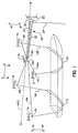
- Figures 1-4 provide various views of the preferred embodiment of the lifting device of the present invention in use to support a watercraft (shown in dashed line).
- Fig. 1 is a perspective view of the preferred lifting device
- Fig. 2 is a top plan view
- Fig. 3 is an elevational view
- Fig. 4 is an elevational view of the preferred device.
- the lifting device as illustrated comprises a first pair of pulleys 2A and 2B, and a second pair of pulleys 4A and 4B.
- Pulleys 2A-B and 4A-B are spaced from one another along a longitudinal axis illustrated as a dashed line and labeled AXIS in Fig. 1 , which passes generally along the center plane between respective pulleys 2A-B and 4A-B.
- Individual pulleys 2A, 2B, 4A, and 4B are thus spaced laterally from AXIS.
- AXIS is preferably substantially parallel to a center longitudinal axis of the boat being lifted.
- Each individual pulley 2A-B and 4A-B are attached to an upright support 6.
- Support 6 may comprise, by way of example, a garage or other structure roof, a frame member that is attached to a garage or other roof, or any other suitable upright support.
- Individual lines 8A, 8B, 10A, and 10B movably pass over respective pulleys 2A, 2B, 4A, and 4B.
- Each individual line 8A-B and 10A-B have means for attachment to the boat.
- preferred attachment means comprise slings 12 and 14, with sling 12 connected to first ends of individual lines 8A and 8B; and sling 14 connected to first ends of individual lines 10A and 10B.
- Preferred slings 12 and 14 are substantially flat for enhanced surface area and resultantly good support characteristics under the boat.
- Preferred slings 12 and 14 also comprise anti-slip surfaces for enhanced gripping power on smooth surfaced objects being lifted, such as fiberglass boats.
- Preferred slings may also comprise contact surfaces that will not mark or otherwise damage such smooth object surfaces.
- the lifting device of the invention may of course be practiced using means other than preferred slings 12 and 14.
- other means may comprise connectors on respective individual line ends for connection to cooperating connectors on the boat, or means comprising underlying supports in a shape different than the substantially flat slings illustrated.
- a single web or net structure may be connected to each of the first ends of the individual lines to underlie and support the object.
- means may comprise lengths of rope connecting the ends of opposing of the individual lines, so that individual lines 8A-B and 10A-B become continuous lengths of rope.
- the preferred lifting device of the present invention further comprises gathering means 16 for organizing the individual lengths of rope 8A-B and 10A-B in a direction substantially along the AXIS.
- Preferred gathering means 16 comprise at least a pair of pulleys 16A and 16B. Additional pulleys may be comprised, but it has been discovered that preferred pair 16A and 16B provide a convenient and cost effective gathering means. If more than two pairs of pulleys 2A-B and 4A-B are comprised, it may be desirable to utilize additional gathering pulleys for orderly organization of the individual lines. Further, it has been discovered that placement of preferred pulleys 16A and 16B transverse from and a short distance from longitudinal AXIS, and inward from pulleys 4A and 4B is advantageous. Gathering pulleys 16A-B are preferably attached to overhead support 6.
- the preferred lifting device further comprises a multiple purchase block and tackle system 18.
- System 18 comprises first end 20 and second end 22, through which hauling line 24 is reeved.
- System 18 runs substantially along longitudinal AXIS, and is spaced from pulley pair 4.
- each system end 20 and 22 comprises a plurality of rotating members 26 around which hauling line 24 is reeved.
- a first end of hauling line 24 is fixably attached to one of system ends 20 or 22 (illustrated as attached to first end 20), with a second end 30 passing through lockable cleat 28 and hanging below second end 22 for adjustment.
- System second end 22 is fixable attached to upright support 32, which may comprise by way of example a garage wall.
- lockable cleat 28 is preferably attached to system second end 22, but may of course likewise be attached to support 32 or be placed at any other suitable location.
- Block and tackle system 18 comprises a purchase ratio of at least 2:1, and preferably 4:1. It has been discovered that 4:1 purchase strikes an advantageous balance between simple, cost effective construction and useful mechanical advantage for raising and lowering watercraft of trailerable dimensions. Greater or lower purchase ratios may of course be comprised to accommodate raising and lowering objects of different weights.
- preferred cleat 28 comprises a cam, with locking surface 50 and cooperating spring loaded pawl arm 52.
- Hauling line 24 passes between pawl arm 52 and locking surface 50, with spring loaded arm 52 urging pawl arm 52 into a locked position.
- Pulling on hauling line 24 urges pawl arm 52 into an open position as indicated by the arrow in Fig. 6 for adjustment of line 24.
- the dog-legged upward bend of pawl arm 52 allows for convenient adjustment of haul line 24 when line 24 is hauled on from below.
- other cleat means may of course be comprised within the device of the present invention and the scope of the attached claims that will allow for adjustable hauling of line 24 with locking of the line upon release.
- individual lines 8A-B and 10A-B are connected to block and tackle system first end 20.
- a user's hauling downwards on hauling line 24 causes preferred cleat 28 pawl arm 52 to move into an open position, after which hauling line may be tightened or loosened. Tightening of hauling line 24 will cause block and tackle system first end 20 to move towards second end 22 with multiple purchase, while loosening of hauling line 24 will cause end 20 to move away from end 22.
- Individual lines 8A-B and 10A-B have second ends attached to block and tackle system first end 20.
- the respective individual lines may be attached by means of connector ring 30 to which each of the respective ends are tied or otherwise tethered. Movement of system first end 20 thereby causes movement of each of individual lines 8A-B and 10A-B. Because the individual lines have been organized by gathering means 16 substantially along the longitudinal AXIS, movement of block and tackle system first end 20 forward and back along AXIS causes movement of each respective individual line a substantially equal distance. This is an important advantage of the lifting device of the present invention as it allows for raising of all portions of the boat an equal simultaneous amount through manipulation of the single hauling line 24.
- pulley pairs 2A-B and 4A-B are preferably spaced in an approximate rectangular fashion. It has been discovered that such a configuration is advantageous for lifting elongate objects such as watercraft. It is noted that although reference to lifting of watercraft is made herein and in the Figs., the lifting device of the present invention is suitable for lifting of a wide variety of objects. By way of example, the lifting device of the invention may be employed to lift convertible hardtops, pickup truck bed covers, motorcycles, and other objects.
- the lifting device of the present invention and as claimed in the attached claims may take configurations other than that as illustrated in Figs. 1-4 .
- Three pulley pairs 100A-B, 101A-B and 102A-B pass individual lines 106-112 to gathering pulleys 104A-B, which are not equally spaced laterally between pulley pairs 100-102 and 102, and which are not spaced laterally between either pulley pairs 100-102.
- Pulley pairs 100-102 are not located along the same longitudinal axis, as may be useful for example to accommodate boats or objects of a particular shape.
- Individual lines 106-112, which are of different lengths, are gathered by gathering pulleys 104 and arranged along longitudinal AXIS, which is not equally spaced between pulleys.
- Block and tackle system 114 operates along AXIS, so that individual lines 106-112 passing through gathering pulleys 104A-B are moved an equal distance when block and tackle system 114 is operated.
- Fig. 7 also illustrates hauling line 116 passing from block and tackle system 114 to remotely mounted cam cleat 118 for adjustment at a position along the side of the boat being lifted.
- the lifting device as configured in Fig. 7 operates in the same general manner as that discussed above with reference to Figs. 1-4 , and with the same advantageous result.
- the lifting device configuration as illustrated in Fig. 7 may be of utility, for instance, to fit a garage having dimensions not allowing for the configuration as illustrated in Figs. 1-4 .
- longitudinal AXIS need not travel in any particular direction.
- longitudinal AXIS may run in a direction substantially perpendicular to the longitudinal axis of the watercraft.
Landscapes
- Engineering & Computer Science (AREA)
- Mechanical Engineering (AREA)
- Ocean & Marine Engineering (AREA)
- Ship Loading And Unloading (AREA)
- Load-Engaging Elements For Cranes (AREA)
- Advancing Webs (AREA)
- Electrical Discharge Machining, Electrochemical Machining, And Combined Machining (AREA)
- Noodles (AREA)
- Magnetic Heads (AREA)
- Valve Device For Special Equipments (AREA)
Abstract
Description
- The present invention relates to lifting devices. More particularly, the present invention relates to an apparatus suspended from an overhead support for lifting an object, especially an elongated object such as a watercraft. Such a lifting device is disclosed for example in
US-A-983 957 , as defined in the preamble of claim 1. - Many types of objects are carried about on trailers or on the tops of motor vehicles, including watercraft. As an example, the owner of a boat may reside some distance from a water body, and not have access to watercraft storage at the body of water. The boat owner may store his boat at his home in a garage, and carry the boat on his automobile roof or on a trailer from the garage to the body of water for use. For storage, the boat must be removed from the automobile or trailer and transferred to a storage position. Many types of boats are sufficiently heavy as to make transfer from the automobile or trailer a difficult or even impossible task for a single individual.
- Lifting devices for such purposes are known in the prior art. These devices as presently known, however, leave many problems unresolved.
- As an example, some prior art lifting devices do not utilize a single haul line. Because of the size and shape of generally elongate objects such as watercraft, multiple support points on the object may be required for raising and lowering. For example, a watercraft may require a support to be placed under it near its stern and a second under it near its bow. These supports must generally be raised or lowered substantially simultaneously. Operation of such devices thus requires one person per support, thereby making operation by a single individual impractical or impossible. Solutions to multiple lifting points requiring multiple individuals have been proposed. These solutions, however, have heretofore been overly complicated and costly.
- Other lifting devices of the prior art are not suitable to lift objects of substantial weight. These devices generally comprise ropes attached to the object and directed through pulleys to a lifting location. Minimal mechanical advantage is provided, however, so that objects of substantial weight, such as a jet ski or small motor boat cannot be lifted by an individual. Lifting devices have been proposed that provide mechanical advantages through cranks, winches, and the like. These devices, however, tend to be overly complicated and expensive, making them impractical and disadvantageous.
- An unresolved need therefore exits for a lifting device suitable for use by a single individual and capable of lifting objects of substantial weight.
- It is an object of the invention to provide a lifting device for lifting an object.
- It is a further object of the invention to provide a lifting device having a mechanical advantage and suitable for lifting a watercraft through manipulation of a single line.
- The present invention comprises a lifting device as defined in the independent claim 1 for raising and lowering an elongate object into a storage position, the lifting device comprising at least a first and a second pair of pulleys, the first and second pairs of pulleys being spaced from one another along a longitudinal axis, each individual pulley of said first and second pair of pulleys spaced laterally from the longitudinal axis, with the first and second pair of pulleys connected to an upright support. Individual lines pass over each individual of the pairs of pulleys, each of the individual lines have means for attachment to the elongate object, and each of the individual lines further comprise second ends.
- The lifting device further comprises a horizontal multiple purchase block and tackle system spaced from one of the pairs of pulleys along the longitudinal axis. The multiple purchase block and tackle system comprises a first and a second end, and an adjustable hauling line reeved between the ends for moving the ends towards one another with multiple purchase. The block and tackle system first end is connected to each of the second ends of the individual lines, and the block and tackle system second end is attached to an upright support such as a garage wall. Hauling on the hauling line thereby urges block and tackle system first end towards the second end along the longitudinal axis, further causing simultaneous movement of the individual lines for raising and lowering the elongate object.
- The present invention thereby presents an apparatus that offers substantial mechanical advantage through the block and tackle system for raising and lowering of objects. Further, because the individual lines are connected to one end of the block and tackle system, the object may be raised or lowered through the manipulation of the haul line only. The lifting device further comprises a lockable cleat located at about the level of the horizontal block and tackle system.
- Preferably, the lifting device further comprises gathering means for gathering and leading the individual lines substantially along the longitudinal axis. Most preferably, the gathering means comprise at least a pair of rotating pulleys. By gathering the individual lines substantially along the longitudinal axis, they may move a substantially equal distance along the axis when the hauling line is hauled to move the ends of the multiple purchase system towards or away from one another. This results in the object being lifted a substantially equal amount by each of the individual lines, for a smooth and level raising.
- The lifting device of the present invention thus comprises a relatively simple to construct, low cost, and easy to install device. Through the multiple purchase block and tackle system the device provides means for lifting objects of substantial weight and size by a single individual through manipulation of a single hauling line. Further, with the preferred gathering means, each of the individual lines may be drawn an equal amount by the block and tackle system so that the object is uniformly raised and lowered by the multiple lines through manipulation of the single haul line. The present invention thus solves several heretofore unresolved problems in an efficient and elegant manner.
-
-
Fig. 1 is a perspective view of an embodiment of the lifting device of the present invention engaging a boat (shown in dashed line). -
Fig. 2 is a top plan view of the embodiment of the lifting device of the invention illustrated inFig. 1 along the line 2-2 ofFig. 1 . -
Fig. 3 is an elevational view of the embodiment of the lifting device of the invention illustrated inFig. 1 along the line 3-3 ofFig. 1 . -
Fig. 4 is an elevational view of the embodiment of the lifting device of the invention illustrated inFig. 1 along the line 4-4 ofFig. 1 . -
Fig. 5 is an illustration of an embodiment of the multiple purchase block and tackle system of the invention. -
Fig. 6 is an illustration of an embodiment of the cleat of the multiple purchase block and tackle system of the invention. -
Fig. 7 is a top plan view of an alternate lifting device configuration of the invention. - In order to better illustrate the lifting device, reference is now made to the drawings.
Figures 1-4 provide various views of the preferred embodiment of the lifting device of the present invention in use to support a watercraft (shown in dashed line). In particular,Fig. 1 is a perspective view of the preferred lifting device,Fig. 2 is a top plan view,Fig. 3 is an elevational view, andFig. 4 is an elevational view of the preferred device. In the following description of the preferred device, reference will be made to common elements as illustrated inFigs. 1-4 . - The lifting device as illustrated comprises a first pair of
pulleys pulleys Pulleys 2A-B and 4A-B are spaced from one another along a longitudinal axis illustrated as a dashed line and labeled AXIS inFig. 1 , which passes generally along the center plane betweenrespective pulleys 2A-B and 4A-B.Individual pulleys individual pulley 2A-B and 4A-B are attached to anupright support 6.Support 6 may comprise, by way of example, a garage or other structure roof, a frame member that is attached to a garage or other roof, or any other suitable upright support.Individual lines respective pulleys individual line 8A-B and 10A-B have means for attachment to the boat. - As illustrated in
Fig. 1 , preferred attachment means compriseslings sling 12 connected to first ends ofindividual lines sling 14 connected to first ends ofindividual lines Preferred slings Preferred slings preferred slings individual lines 8A-B and 10A-B become continuous lengths of rope. - The preferred lifting device of the present invention further comprises gathering means 16 for organizing the individual lengths of
rope 8A-B and 10A-B in a direction substantially along the AXIS. Preferred gathering means 16 comprise at least a pair ofpulleys preferred pair pulleys 2A-B and 4A-B are comprised, it may be desirable to utilize additional gathering pulleys for orderly organization of the individual lines. Further, it has been discovered that placement ofpreferred pulleys pulleys overhead support 6. - The preferred lifting device further comprises a multiple purchase block and
tackle system 18.System 18 comprisesfirst end 20 andsecond end 22, through which haulingline 24 is reeved.System 18 runs substantially along longitudinal AXIS, and is spaced from pulley pair 4. As best illustrated inFig. 5 , each system end 20 and 22 comprises a plurality of rotatingmembers 26 around which haulingline 24 is reeved. A first end of haulingline 24 is fixably attached to one of system ends 20 or 22 (illustrated as attached to first end 20), with asecond end 30 passing throughlockable cleat 28 and hanging belowsecond end 22 for adjustment. Systemsecond end 22 is fixable attached toupright support 32, which may comprise by way of example a garage wall. As illustrated,lockable cleat 28 is preferably attached to systemsecond end 22, but may of course likewise be attached to support 32 or be placed at any other suitable location. - Block and tackle
system 18 comprises a purchase ratio of at least 2:1, and preferably 4:1. It has been discovered that 4:1 purchase strikes an advantageous balance between simple, cost effective construction and useful mechanical advantage for raising and lowering watercraft of trailerable dimensions. Greater or lower purchase ratios may of course be comprised to accommodate raising and lowering objects of different weights. - As best illustrated in
Fig. 6 ,preferred cleat 28 comprises a cam, with lockingsurface 50 and cooperating spring loaded pawl arm 52. Haulingline 24 passes between pawl arm 52 and lockingsurface 50, with spring loaded arm 52 urging pawl arm 52 into a locked position. Pulling on haulingline 24 urges pawl arm 52 into an open position as indicated by the arrow inFig. 6 for adjustment ofline 24. The dog-legged upward bend of pawl arm 52 allows for convenient adjustment ofhaul line 24 whenline 24 is hauled on from below. In addition topreferred cam 28, other cleat means may of course be comprised within the device of the present invention and the scope of the attached claims that will allow for adjustable hauling ofline 24 with locking of the line upon release. - Referring once again to
Figs. 1-4 and toFig. 5 in particular,individual lines 8A-B and 10A-B are connected to block and tackle systemfirst end 20. A user's hauling downwards on haulingline 24 causes preferredcleat 28 pawl arm 52 to move into an open position, after which hauling line may be tightened or loosened. Tightening of haulingline 24 will cause block and tackle systemfirst end 20 to move towardssecond end 22 with multiple purchase, while loosening of haulingline 24 will cause end 20 to move away fromend 22. -
Individual lines 8A-B and 10A-B have second ends attached to block and tackle systemfirst end 20. As best illustrated inFig. 5 , the respective individual lines may be attached by means ofconnector ring 30 to which each of the respective ends are tied or otherwise tethered. Movement of systemfirst end 20 thereby causes movement of each ofindividual lines 8A-B and 10A-B. Because the individual lines have been organized by gathering means 16 substantially along the longitudinal AXIS, movement of block and tackle systemfirst end 20 forward and back along AXIS causes movement of each respective individual line a substantially equal distance. This is an important advantage of the lifting device of the present invention as it allows for raising of all portions of the boat an equal simultaneous amount through manipulation of thesingle hauling line 24. - As generally illustrated in
Figs. 1-4 , pulley pairs 2A-B and 4A-B are preferably spaced in an approximate rectangular fashion. It has been discovered that such a configuration is advantageous for lifting elongate objects such as watercraft. It is noted that although reference to lifting of watercraft is made herein and in the Figs., the lifting device of the present invention is suitable for lifting of a wide variety of objects. By way of example, the lifting device of the invention may be employed to lift convertible hardtops, pickup truck bed covers, motorcycles, and other objects. - Further, as will be appreciated by those knowledgeable in the art, the lifting device of the present invention and as claimed in the attached claims may take configurations other than that as illustrated in
Figs. 1-4 . By way of example and not limitation, reference is made to the top plan view ofFig.7 of an alternate lifting device configuration. Three pulley pairs 100A-B, 101A-B and 102A-B pass individual lines 106-112 to gatheringpulleys 104A-B, which are not equally spaced laterally between pulley pairs 100-102 and 102, and which are not spaced laterally between either pulley pairs 100-102. Pulley pairs 100-102 are not located along the same longitudinal axis, as may be useful for example to accommodate boats or objects of a particular shape. Individual lines 106-112, which are of different lengths, are gathered by gathering pulleys 104 and arranged along longitudinal AXIS, which is not equally spaced between pulleys. - Block and
tackle system 114 operates along AXIS, so that individual lines 106-112 passing through gathering pulleys 104A-B are moved an equal distance when block andtackle system 114 is operated.Fig. 7 also illustrates haulingline 116 passing from block andtackle system 114 to remotely mountedcam cleat 118 for adjustment at a position along the side of the boat being lifted. The lifting device as configured inFig. 7 operates in the same general manner as that discussed above with reference toFigs. 1-4 , and with the same advantageous result. The lifting device configuration as illustrated inFig. 7 may be of utility, for instance, to fit a garage having dimensions not allowing for the configuration as illustrated inFigs. 1-4 . - It is further noted that longitudinal AXIS need not travel in any particular direction. As an example, longitudinal AXIS may run in a direction substantially perpendicular to the longitudinal axis of the watercraft.
- The advantages of the disclosed invention are thus attained in an ecomonical, practical, and facile manner. While example embodiments have been shown and described, it is to be understood that various further modifications and additional configurations will be apparent to those skilled in the art. It is intended that the specific embodiments herein disclosed are illustrative of the preferred and best modes for practicing the invention only, and should not be interpreted as limitations on the scope of the invention as defined by the appended claims.
Claims (14)
- A lifting device for use in removing an elongated object from a motor vehicle for storage in a garage in which the motor vehicle is stored, said elongated object being stored above the motor vehicle when parked in the garage, the elongate object having a first longitudinal axis; the lifting device comprising:at least a first and a second pair of pulleys (2A, 2B, 4A, 4B), said first and second pairs of pulleys (2A, 2B, 4A, 4B) being spaced from one another along a second longitudinal axis, each individual pulley (2A, 2B, 4A) of said first and second pair of pulleys spaced laterally from said second longitudinal axis, each of said first and second pair of pulleys (2A, 2B, 4A, 4B) adapted to be connected to an upright support (6); andindividual lines (8A, 8B, 10A, 10B) passing over each individual of said pairs of pulleys (2A, 2B, 4A, 4B) each of said individual lines (8A, 8B, 10A, 10B) having means (12,14) for attachment to the elongate object, each of said individual lines (8A, 8B, 10A, 10B) having second ends;characterized by a horizontal multiple purchase block and tackle system (18) spaced from one of said pairs of pulleys (2A, 2B, 4A, 4B) along said second longitudinal axis, said multiple purchase block and tackle system comprising a first and a second end (20, 22), an adjustable hauling line means (24) reeved between said block and tackle first and second ends (20,22) and adapted to extend down beside the parked motor vehicle, for moving said block and tackle system ends (20,22) towards one another with multiple purchase, said block and tackle system first end (20) connected to said second ends of said individual lines (8A, 8B, 10A, 10B) said block and tackle second end (22) adapted to be attached to an upright support (32), whereby hauling on said hauling line causes said block and tackle first end to move towards said block and tackle system second end and said individual lines are thereby simultaneously moved and whereby a lockable cleat (28) is located at about the level of the horizontal block and tackle system (18) and adapted to be reached by the operator when the motor vehicle is parked below the raised elongated object.
- A lifting device as in claim 1, wherein the lifting device further comprises means (16) for gathering and leading said individual lines (8A, 8B, 10A, 10B) substantially along said second longitudinal axis, whereby said individual lines second ends attached to said block and tackle system first end will be moved by said block and tackle system first end substantially along said second longitudinal axis.
- A lifting device as in claim 2, whereing said means for gathering and leading said second ends of said individual lines comprises at least a pair of rotating members (16A, 16B) spaced inwardly from one of said first and second pairs of pulleys (2A, 2B, 4A, 4B).
- A lifting device as in claim 3, wherein said at least a pair of rotating members comprise a pair of spaced pulleys (16A, 16B).
- A lifting device as in claim 3, wherein said rotating members (16A, 16B) are located transverse to said longitudinal axis.
- A lifting device as in claim 5, wherein said rotating members (16A, 16B) are adapted to be secured on said upright support (6) centrally between one of said first or second pairs of pulleys (2A, 2B, 4A, 4B).
- A lifting device as in claim 1, wherein said means for attaching the elongate object at said first ends of said individual lines (8A, 8B, 10A, 10B) comprises a sling (12,14) passing beneath the elongate object for supporting the object, said sling (12,14) traveling substantially transverse to the elongate object first longitudinal axis.
- A lifting device as in claim 1, wherein said cam cleat (28) is connected to said block and tackle system second end (22), said cam cleat (28) further comprising a locking surface (50) and a cooperating spring loaded pawl arm (52), said spring loaded pawl arm (52) positioned below said locking member (50) with said hauling line passing therebetween, whereby said spring loaded pawl arm urges said hauling line (24) into a locked position when said hauling line (24) hangs free, and whereby hauling on said hauling line (24) urges said spring loaded pawl into an open unlocked position whereby said hauling line (24) may be adjusted.
- A lifting device as in claim 1, wherein said at least two pairs of pulleys (2A, 2B, 4A, 4B) are arranged in a substantially rectangular position.
- A lifting device as in claim 1, wherein said at least two pairs of pulleys (2A, 2B, 4A, 4B) are equally spaced from said second longitudinal axis.
- A lifting device as in claim 1, wherein said second longitudinal axis is substantially parallel to the first longitudinal axis.
- A lifting device as in claim 1, wherein hauling on said hauling line (24) causes simultaneous movement of each of said individual lines (8A, 8B, 10A, 10B), each of said individual lines (8A, 8B, 10A, 10B) moving a substantially equal distance along said longitudinal axis.
- A lifting device as in claim 1, wherein said multiple purchase block and tackle system (18) comprises a 4:1 purchase ratio.
- A lifting device as in any of the preceding claims, wherein the elongate object is a watercraft and the storage position is in the garage, said garage having a ceiling and a wall, characterized in that
said first and second pair of pulleys (2A, 2B, 4A, 4B) are adapted to be connected to the ceiling (6);
each of said individual lines (8A, 8B, 10A, 10B) has first ends connected to substantially flat slings (12,14), said substantially flat slings underlying and supporting the watercraft, said slings (12,14) passing under the watercraft substantially transverse to the watercraft first longitudinal axis;
at least a pair of gathering pulleys (16A, 16B) is located substantially along said second longitudinal axis between said first pair of pulleys (4A, 4B), said at least a pair of gathering pulleys (16A, 16B) for gathering said individual lines (8A, 8B, 10A, 10B) along said second longitudinal axis; said gathering pulleys being adapted to be attached to the ceiling (6);
said multiple purchase block and tackle system is spaced from said gathering pulleys (16A, 16B) along said second longitudinal axis; said block and tackle second end is adapted to be fixably attached to the garage wall; whereby hauling on said hauling line causes simultaneous movement of each of said individual lines a substantially equal distance for raising and lowering said watercraft.
Applications Claiming Priority (3)
| Application Number | Priority Date | Filing Date | Title |
|---|---|---|---|
| US09/640,411 US6361022B1 (en) | 2000-08-17 | 2000-08-17 | Lifting device |
| US640411 | 2000-08-17 | ||
| PCT/US2001/041747 WO2002014205A2 (en) | 2000-08-17 | 2001-08-16 | Lifting device |
Publications (3)
| Publication Number | Publication Date |
|---|---|
| EP1328463A2 EP1328463A2 (en) | 2003-07-23 |
| EP1328463A4 EP1328463A4 (en) | 2006-03-29 |
| EP1328463B1 true EP1328463B1 (en) | 2009-10-07 |
Family
ID=24568120
Family Applications (1)
| Application Number | Title | Priority Date | Filing Date |
|---|---|---|---|
| EP01964611A Expired - Lifetime EP1328463B1 (en) | 2000-08-17 | 2001-08-16 | Lifting device |
Country Status (6)
| Country | Link |
|---|---|
| US (1) | US6361022B1 (en) |
| EP (1) | EP1328463B1 (en) |
| AT (1) | ATE444934T1 (en) |
| AU (1) | AU2001285448A1 (en) |
| DE (1) | DE60140137D1 (en) |
| WO (1) | WO2002014205A2 (en) |
Families Citing this family (9)
| Publication number | Priority date | Publication date | Assignee | Title |
|---|---|---|---|---|
| US8328029B1 (en) | 2002-04-09 | 2012-12-11 | Binsfeld Arthur J | Storage rack |
| US6959918B1 (en) * | 2004-01-13 | 2005-11-01 | Samuels Jeffrey L | Truck canopy lifting assembly |
| US7325785B2 (en) * | 2004-12-03 | 2008-02-05 | The Design Society, Inc. | Storage apparatus |
| US20080087787A1 (en) * | 2006-10-16 | 2008-04-17 | Michael Baumer | Apparatus for overhead storage |
| US20080203046A1 (en) * | 2007-02-28 | 2008-08-28 | Allan Friesen | Overhead lift storage device |
| CA2904520A1 (en) * | 2014-09-12 | 2016-03-12 | Michael A. BONDI | Household object storage system |
| US10421512B2 (en) * | 2017-01-09 | 2019-09-24 | Larry Stirling | Convertible top removal device and method |
| US10569997B1 (en) * | 2019-05-03 | 2020-02-25 | Ricky Fusillo | Lifting device |
| CN112918636B (en) * | 2021-03-17 | 2022-01-25 | 沈海龙 | A sea-condition-adaptive deployment and recovery device for rapid deployment of unmanned boats |
Family Cites Families (15)
| Publication number | Priority date | Publication date | Assignee | Title |
|---|---|---|---|---|
| US741583A (en) * | 1902-10-20 | 1903-10-13 | Florida E Lawrence | Burial apparatus. |
| US983957A (en) * | 1909-12-24 | 1911-02-14 | Lizzie Trantham | Quilting-frame. |
| US3112816A (en) * | 1959-09-29 | 1963-12-03 | Halford Wilfrid Charles Julian | Block and tackle apparatus with rope brake means |
| CH609934A5 (en) * | 1975-09-12 | 1979-03-30 | Mubir Ag Masch & App | Pulley block with rope-clamping device |
| FR2422582A1 (en) * | 1978-04-12 | 1979-11-09 | Coignet Sa | MOLDING COMPOSITION DETECTOR OF A LIFTING END |
| DE3323138A1 (en) * | 1983-06-27 | 1985-01-10 | Helmut Dr. 8031 Alling Forster | GRAVITY RELIEF DEVICE |
| US4600177A (en) * | 1984-04-12 | 1986-07-15 | Precision Auto Designs, Inc. | Method of hoisting an automobile hard top |
| US5037237A (en) * | 1989-08-28 | 1991-08-06 | Anteau Paul D | Boat hull protector and method of handling a boat |
| US5051027A (en) * | 1989-12-15 | 1991-09-24 | Horton George F | Boat lift |
| US5297832A (en) * | 1993-01-07 | 1994-03-29 | Fred Dewey | Log lifting beam assembly |
| US5281077A (en) * | 1993-03-23 | 1994-01-25 | Phillips Gary C | Portable watercraft lift |
| US5897104A (en) * | 1996-05-03 | 1999-04-27 | Garbiso; Michael J. | Overhead hoist and sling apparatus for removing, storing and replacing a removable automobile hardtop |
| US6056274A (en) * | 1997-06-03 | 2000-05-02 | Naas; Jane Eldredge | Boat hoist apparatus |
| US6152427A (en) * | 1998-08-26 | 2000-11-28 | Hoslett; Glenn J. | Truck cap hoisting system |
| US5984275A (en) * | 1998-08-26 | 1999-11-16 | Hoslett; Glenn J. | Truck cap hoisting system |
-
2000
- 2000-08-17 US US09/640,411 patent/US6361022B1/en not_active Expired - Lifetime
-
2001
- 2001-08-16 WO PCT/US2001/041747 patent/WO2002014205A2/en not_active Ceased
- 2001-08-16 EP EP01964611A patent/EP1328463B1/en not_active Expired - Lifetime
- 2001-08-16 AT AT01964611T patent/ATE444934T1/en not_active IP Right Cessation
- 2001-08-16 AU AU2001285448A patent/AU2001285448A1/en not_active Abandoned
- 2001-08-16 DE DE60140137T patent/DE60140137D1/en not_active Expired - Lifetime
Also Published As
| Publication number | Publication date |
|---|---|
| WO2002014205A3 (en) | 2003-02-06 |
| AU2001285448A1 (en) | 2002-02-25 |
| EP1328463A4 (en) | 2006-03-29 |
| EP1328463A2 (en) | 2003-07-23 |
| US6361022B1 (en) | 2002-03-26 |
| WO2002014205A2 (en) | 2002-02-21 |
| DE60140137D1 (en) | 2009-11-19 |
| ATE444934T1 (en) | 2009-10-15 |
Similar Documents
| Publication | Publication Date | Title |
|---|---|---|
| US6386515B1 (en) | Device to install/remove truck cap | |
| US6499610B2 (en) | Portable hoist system | |
| US6591770B1 (en) | Boating lift | |
| US6056274A (en) | Boat hoist apparatus | |
| US4439086A (en) | Boat loader | |
| US5281077A (en) | Portable watercraft lift | |
| US4600177A (en) | Method of hoisting an automobile hard top | |
| US4046273A (en) | Canoe loading apparatus | |
| US3894643A (en) | Loading hoist for boats | |
| US6361022B1 (en) | Lifting device | |
| US7246712B2 (en) | Logging carriage with towline-operated grapple | |
| US6846129B1 (en) | Boatlift and movable canopy assembly | |
| US6857620B2 (en) | Method and apparatus for truck tarp loading | |
| US7001104B2 (en) | Boatlift and movable canopy assembly | |
| US6029598A (en) | Trailerable houseboat/camper with removable pontoons | |
| US9963329B1 (en) | Utility task vehicle (UTV) accessory for a side-by-side UTV having a front-mounted winch | |
| JPH06156975A (en) | Suspension cargo turning control method | |
| US5460472A (en) | Cartop hoist and carrier | |
| US5865136A (en) | System for lifting and lowering a sailboat mast | |
| US20050087116A1 (en) | Watercraft lifts and cable tie-off device for watercraft lifts | |
| US5193872A (en) | Line laying device for mooring a platform | |
| US4601633A (en) | Hoist | |
| JPS6124476Y2 (en) | ||
| JPS5932339B2 (en) | roof carrier | |
| CN217051397U (en) | Pipeline hoisting device |
Legal Events
| Date | Code | Title | Description |
|---|---|---|---|
| PUAI | Public reference made under article 153(3) epc to a published international application that has entered the european phase |
Free format text: ORIGINAL CODE: 0009012 |
|
| 17P | Request for examination filed |
Effective date: 20030312 |
|
| AK | Designated contracting states |
Designated state(s): AT BE CH CY DE DK ES FI FR GB GR IE IT LI LU MC NL PT SE TR |
|
| AX | Request for extension of the european patent |
Extension state: AL LT LV MK RO SI |
|
| A4 | Supplementary search report drawn up and despatched |
Effective date: 20060214 |
|
| RIC1 | Information provided on ipc code assigned before grant |
Ipc: B63C 15/00 20060101ALI20060208BHEP Ipc: B66C 13/02 20060101ALI20060208BHEP Ipc: B66F 1/00 20060101AFI20020226BHEP |
|
| 17Q | First examination report despatched |
Effective date: 20061010 |
|
| 17Q | First examination report despatched |
Effective date: 20061010 |
|
| GRAP | Despatch of communication of intention to grant a patent |
Free format text: ORIGINAL CODE: EPIDOSNIGR1 |
|
| GRAS | Grant fee paid |
Free format text: ORIGINAL CODE: EPIDOSNIGR3 |
|
| GRAA | (expected) grant |
Free format text: ORIGINAL CODE: 0009210 |
|
| AK | Designated contracting states |
Kind code of ref document: B1 Designated state(s): AT BE CH CY DE DK ES FI FR GB GR IE IT LI LU MC NL PT SE TR |
|
| REG | Reference to a national code |
Ref country code: GB Ref legal event code: FG4D |
|
| REG | Reference to a national code |
Ref country code: CH Ref legal event code: EP |
|
| REG | Reference to a national code |
Ref country code: IE Ref legal event code: FG4D |
|
| REF | Corresponds to: |
Ref document number: 60140137 Country of ref document: DE Date of ref document: 20091119 Kind code of ref document: P |
|
| NLV1 | Nl: lapsed or annulled due to failure to fulfill the requirements of art. 29p and 29m of the patents act | ||
| PG25 | Lapsed in a contracting state [announced via postgrant information from national office to epo] |
Ref country code: FI Free format text: LAPSE BECAUSE OF FAILURE TO SUBMIT A TRANSLATION OF THE DESCRIPTION OR TO PAY THE FEE WITHIN THE PRESCRIBED TIME-LIMIT Effective date: 20091007 Ref country code: PT Free format text: LAPSE BECAUSE OF FAILURE TO SUBMIT A TRANSLATION OF THE DESCRIPTION OR TO PAY THE FEE WITHIN THE PRESCRIBED TIME-LIMIT Effective date: 20100208 Ref country code: ES Free format text: LAPSE BECAUSE OF FAILURE TO SUBMIT A TRANSLATION OF THE DESCRIPTION OR TO PAY THE FEE WITHIN THE PRESCRIBED TIME-LIMIT Effective date: 20100118 Ref country code: SE Free format text: LAPSE BECAUSE OF FAILURE TO SUBMIT A TRANSLATION OF THE DESCRIPTION OR TO PAY THE FEE WITHIN THE PRESCRIBED TIME-LIMIT Effective date: 20091007 |
|
| PG25 | Lapsed in a contracting state [announced via postgrant information from national office to epo] |
Ref country code: AT Free format text: LAPSE BECAUSE OF FAILURE TO SUBMIT A TRANSLATION OF THE DESCRIPTION OR TO PAY THE FEE WITHIN THE PRESCRIBED TIME-LIMIT Effective date: 20091007 Ref country code: BE Free format text: LAPSE BECAUSE OF FAILURE TO SUBMIT A TRANSLATION OF THE DESCRIPTION OR TO PAY THE FEE WITHIN THE PRESCRIBED TIME-LIMIT Effective date: 20091007 |
|
| PG25 | Lapsed in a contracting state [announced via postgrant information from national office to epo] |
Ref country code: NL Free format text: LAPSE BECAUSE OF FAILURE TO SUBMIT A TRANSLATION OF THE DESCRIPTION OR TO PAY THE FEE WITHIN THE PRESCRIBED TIME-LIMIT Effective date: 20091007 Ref country code: DK Free format text: LAPSE BECAUSE OF FAILURE TO SUBMIT A TRANSLATION OF THE DESCRIPTION OR TO PAY THE FEE WITHIN THE PRESCRIBED TIME-LIMIT Effective date: 20091007 |
|
| PLBE | No opposition filed within time limit |
Free format text: ORIGINAL CODE: 0009261 |
|
| STAA | Information on the status of an ep patent application or granted ep patent |
Free format text: STATUS: NO OPPOSITION FILED WITHIN TIME LIMIT |
|
| 26N | No opposition filed |
Effective date: 20100708 |
|
| PG25 | Lapsed in a contracting state [announced via postgrant information from national office to epo] |
Ref country code: GR Free format text: LAPSE BECAUSE OF FAILURE TO SUBMIT A TRANSLATION OF THE DESCRIPTION OR TO PAY THE FEE WITHIN THE PRESCRIBED TIME-LIMIT Effective date: 20100108 |
|
| PG25 | Lapsed in a contracting state [announced via postgrant information from national office to epo] |
Ref country code: MC Free format text: LAPSE BECAUSE OF NON-PAYMENT OF DUE FEES Effective date: 20100831 Ref country code: IT Free format text: LAPSE BECAUSE OF FAILURE TO SUBMIT A TRANSLATION OF THE DESCRIPTION OR TO PAY THE FEE WITHIN THE PRESCRIBED TIME-LIMIT Effective date: 20091007 |
|
| REG | Reference to a national code |
Ref country code: CH Ref legal event code: PL |
|
| GBPC | Gb: european patent ceased through non-payment of renewal fee |
Effective date: 20100816 |
|
| PG25 | Lapsed in a contracting state [announced via postgrant information from national office to epo] |
Ref country code: LI Free format text: LAPSE BECAUSE OF NON-PAYMENT OF DUE FEES Effective date: 20100831 Ref country code: CH Free format text: LAPSE BECAUSE OF NON-PAYMENT OF DUE FEES Effective date: 20100831 |
|
| REG | Reference to a national code |
Ref country code: FR Ref legal event code: ST Effective date: 20110502 |
|
| REG | Reference to a national code |
Ref country code: DE Ref legal event code: R119 Ref document number: 60140137 Country of ref document: DE Effective date: 20110301 |
|
| PG25 | Lapsed in a contracting state [announced via postgrant information from national office to epo] |
Ref country code: IE Free format text: LAPSE BECAUSE OF NON-PAYMENT OF DUE FEES Effective date: 20100816 Ref country code: DE Free format text: LAPSE BECAUSE OF NON-PAYMENT OF DUE FEES Effective date: 20110301 Ref country code: FR Free format text: LAPSE BECAUSE OF NON-PAYMENT OF DUE FEES Effective date: 20100831 |
|
| PG25 | Lapsed in a contracting state [announced via postgrant information from national office to epo] |
Ref country code: GB Free format text: LAPSE BECAUSE OF NON-PAYMENT OF DUE FEES Effective date: 20100816 |
|
| PG25 | Lapsed in a contracting state [announced via postgrant information from national office to epo] |
Ref country code: CY Free format text: LAPSE BECAUSE OF FAILURE TO SUBMIT A TRANSLATION OF THE DESCRIPTION OR TO PAY THE FEE WITHIN THE PRESCRIBED TIME-LIMIT Effective date: 20091007 |
|
| PG25 | Lapsed in a contracting state [announced via postgrant information from national office to epo] |
Ref country code: LU Free format text: LAPSE BECAUSE OF NON-PAYMENT OF DUE FEES Effective date: 20100816 |
|
| PG25 | Lapsed in a contracting state [announced via postgrant information from national office to epo] |
Ref country code: TR Free format text: LAPSE BECAUSE OF FAILURE TO SUBMIT A TRANSLATION OF THE DESCRIPTION OR TO PAY THE FEE WITHIN THE PRESCRIBED TIME-LIMIT Effective date: 20091007 |