EP1328058A2 - Rotary electric machine and method for connecting stator conductors - Google Patents
Rotary electric machine and method for connecting stator conductors Download PDFInfo
- Publication number
- EP1328058A2 EP1328058A2 EP02015573A EP02015573A EP1328058A2 EP 1328058 A2 EP1328058 A2 EP 1328058A2 EP 02015573 A EP02015573 A EP 02015573A EP 02015573 A EP02015573 A EP 02015573A EP 1328058 A2 EP1328058 A2 EP 1328058A2
- Authority
- EP
- European Patent Office
- Prior art keywords
- joint terminal
- jointing
- electric machine
- rotary electric
- lead wire
- Prior art date
- Legal status (The legal status is an assumption and is not a legal conclusion. Google has not performed a legal analysis and makes no representation as to the accuracy of the status listed.)
- Granted
Links
Images


Classifications
-
- H—ELECTRICITY
- H02—GENERATION; CONVERSION OR DISTRIBUTION OF ELECTRIC POWER
- H02K—DYNAMO-ELECTRIC MACHINES
- H02K3/00—Details of windings
- H02K3/46—Fastening of windings on the stator or rotor structure
- H02K3/50—Fastening of winding heads, equalising connectors, or connections thereto
Definitions
- the present invention relates to a rotary electric machine such as an AC generator for vehicle and a method for producing the rotary electric machine, in particular to a processing of a terminal of lead conductor of a stator.
- a three-phase AC generator ordinarily having a rotor of a claw-like magnetic pole type is used for a generator equipped in a vehicle.
- the AC generator has a structure, for example, disclosed in Japanese Unexamined Patent Publication JP-A-4-168952, such that a three-phase stator coil is wound around a stator core on the stator side, the stator coil has lead conductors, a metallic terminal is attached to the ends of the lead conductors and connected and fixed to a three-phase full wave rectifier located on a bracket.
- the stator coil is, for example, a polyamide-imide electric wire, being a copper wire having an insulating coating of high heat resistance.
- the lead conductor is the copper wire, i.e.
- the metallic terminal is made from a metal like copper and jointed to the lead conductor by soldering, caulking with soldering, fusing, or by an equivalent means thereto.
- the metallic terminal is fixed to the rectifier using a screw or the like.
- a rotary electric machine such as an AC generator for vehicle is generally mounted on an engine frame inside an engine room of vehicle, where an atmospheric temperature is high and vibration applied to the engine is strong.
- the temperature of a stator coil becomes high by heat caused by generated electric current and the high atmospheric temperature. Therefore, when the lead conductor of the stator coil is jointed to the metallic terminal by soldering as described above, heat deterioration progresses, and the junction resistance of the jointed portion may increase to resultantly disconnect.
- a use of a high temperature solder having a high Pb ingredient rate is inevitable.
- the high temperature solder having the high Pb ingredient rate deteriorates working atmosphere and the reliability is lowered because workability becomes extremely unfavorable.
- the jointing by fusing has deficiencies that the shape of a jointed portion and the junction resistance are not stabilized because the jointed portion is welded with pressure applied, and fatigue breakdown is apt to occur by vibration generated by the engine.
- the lead conductors and the metallic terminal are jointed only by caulking, the strength and the junction resistance are not stabilized.
- a device described in Japanese Unexamined Patent Publication JP-A-10-4646 can be mentioned. In this device, a focused terminal and an enameled copper wire are subjected to pressure resistance welding using a brazing filler metal on a jointed surface between the focus terminal and the enameled copper wire.
- a rotary electric machine comprising:
- the rotary electric machine wherein a recess is formed on an inner surface of the hole of the joint terminal along the outer periphery of the lead wire after the welding, whereby it is possible to obtain the rotary electric machine having a low junction resistance and high reliability.
- the rotary electric machine wherein the jointing ancillary agent is tinning, whereby it is possible to easily plate at a low cost while making the joint firm and improving anticorrosive capability.
- the rotary electric machine wherein the jointing ancillary agent is galvanization, whereby it is possible to easily plate at a low cost while making the joint firm and improving anticorrosive capability.
- the joint terminal is formed by rounding a conductive metallic plate in a tubular form and a butted portion is jointed using a brazing filler material having a melt point higher than the carbonization temperature of the insulating coating of the lead wire to form the tubular hole, whereby it is possible to easily change the diameter of the hole and make the reliability of the jointed portion high because the welding is tight and therefore the dimensions are stabilized.
- the brazing filler material for jointing the butted portion is a phosphor copper brazing filler, whereby it is possible to make the joint firm and the junction resistance small to enhance the reliability.
- the rotary electric machine wherein the lead wire is jointed by welding at a temperature of the melt point of the brazing filler material for jointing the butted portion or less, whereby it is possible to make the junction resistance small and the jointing firm with high reliability, enhance productivity, and improve insulation and vibration proof.
- the rotary electric machine wherein the lead wire is arranged in one row inside the hole of the joint terminal after the welding, whereby it is possible to make the joint strength high, the junction resistance small, and the reliability of the jointed portion high.
- the rotary electric machine wherein the lead wire is arranged in two rows in an offsetting manner inside the hole of the joint terminal after the welding, whereby it is possible to miniaturize the machine and enhance the productivity.
- a method for producing a rotary electric machine comprising steps of:
- the method for producing the rotary electric machine wherein the step of forming the joint terminal having the segue tubular hole is rounding a conductive metallic plate in a tubular form and jointing a butted portion using a brazing filler material having a melt point higher than a carbonization temperature of the insulating coating of the lead wire, and forming the segue tubular hole, whereby it is possible to make the cost of the joint terminal low, stabilize the dimensions of the welded portion, and enhance the reliability of the jointed portion.
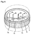
- Figs. 1a through 2, 5 and 6 illustrate an AC generator for vehicle according to Embodiment 1 and a method for producing the AC generator.
- Figs. 1a through 1d illustrate for explaining a jointed state between a lead conductor of a stator coil and a joint terminal and a step of jointing these.
- Fig. 2 is a cross-sectional view for explaining the jointed state after welding these.
- Fig. 5 is a cross-sectional view illustrating an entire structure of an AC generator for vehicle.
- Fig. 6 is a perspective view illustrating a structure of stator. In Fig.
- numerical reference 1 designates a front bracket
- numerical reference 2 designates a rear bracket
- numerical reference 3 designates a stator interposed and held between front bracket 1 and rear bracket 1 and including stator core 4 and stator coil 5
- numerical reference 6 designates a rotor including rotational shaft 7 supported by front bracket 1 and rear bracket 2 at both ends, rotor cores 8 and 9 attached to rotational shaft 7, field coil 10 wound between rotor cores 8 and 9, fans 11 and 12 located on back surfaces of rotor cores 8 and 9, and slip ring 13 for supplying electric current to field coil 10, which is located in rotational shaft 7.
- Numerical reference 14 designates a pulley located in rotational shaft 7.
- Lead conductors 19a, 19b, 19c and 19d respectively of stator coils 5a, 5b, 5c and 5d are elongated on the side of rear bracket, and joint terminals 20 are connected to their tip ends so as to be connected and fixed to terminal 17a of rectifier 17 as illustrated in Fig. 5.
- Fig. 6 illustrates a star connection type stator, lead conductor 19d opposite to stator coils 5a, 5b and 5c are connected in block so as to form neutral point 5d and welded to joint terminal 21 so as to be connected to rectifier 17 in a manner similar thereto.
- rotor cores 8 and 9 are opposite to an inner peripheral portion of stator core 4 interposing a predetermined gap, and rotor cores 8 and 9 are arranged so as to be mutually engaged and respectively have magnetic pole pieces 8a and 9a, alternately magnetized to an opposite magnetic polarity.
- Field coil 10 is excited by a battery (not shown) through brushes 15 and slip ring 13. Then rotor 6 is driven by the engine through pulley 14 to generate a rotating field, three-phase AC power is generated in stator coil 5. The generated power is transformed to DC power by rectifier 17 to charge the battery. Then the power is supplied to loads (not shown).
- Stator coils 5a, 5b and 5c on a path for supplying the power are lead wires having insulating coatings, wherein an insulating coating made from, for example, an amide-imide system is uniformly baked on an outer periphery of a copper wire.
- Lead conductors 19a, 19b and 19c are welded to join terminal 20 without removing the insulating coating.
- lead conductor 19d on the neutral point is welded to join terminal 21 without removing the insulating coating.
- Figs. 1a through 1d illustrate a state that joint terminal 21 is jointed and the step of jointing this.
- Fig. 2 is a cross-sectional view illustrating the jointed state after the welding.
- Fig. 1a illustrates the state that six lead conductors 19d are inserted in tubular hole 22 of joint terminal 21, wherein joint terminal 21 is made of a copper plate, hole 22 is formed by rounding the copper plate like a tube and jointing butted portion 23 using phosphor copper brazing filler 24 so as to be segue tubular hole 22, and thereafter tinning of a thickness of 5 ⁇ m is provided on the entire surface of joint terminal 21.
- Fig. 1b illustrates a state that pressure resistance welding is performed by applying electric current and pressure by electrodes 25 to the state illustrated in Fig. 1a, wherein the welding temperature is about 650°C, tubular hole 22 is flattened by the increased pressure and temperature six lead conductors 19d are arranged in one row in flattened hole 22.
- Fig. 1c is a cross-sectional view after the welding.
- Fig. 1d is a plan view of Fig. 1c.
- Fig. 2 is an enlarged view of Fig. 1c, wherein the jointed state after the welding is illustrated, wherein on the inner surface of hole 22 of joint terminal 21, recesses 26 are formed along the outer peripheries of lead conductors 19d, and lead conductors 19d are also subjected to plastic deformation to be in an elliptic shape.
- the carbonization temperature of the insulating coating made from the amide-imide system is about 600°C.
- Carbonized insulating coating 27 gathers gaps between lead conductors 19d and tin 28, and intervenes and remains between recesses 26 and lead conductors 19d, from which the insulating coating is removed. Because the melt point of phosphor copper brazing filler 24 is about 840°C and the welding temperature is about 650°C, phosphor copper brazing filler 24 is not melted to keep the segue tubular state.
- joint terminal 21 has segue tubular hole 22, the tinning having the melting temperature less than the carbonization temperature of insulating coating 27 of lead conductor 19d is provided on the entire surface of joint terminal 21, and lead conductors 19d inserted in hole 22 are welded to joint terminal 21 via tin 28 as the ancillary agent to form segue tubular hole 22, lead conductors 19d are easily inserted and held to make the productivity good, the welded portion does not expand and are welded under the tightened state to thereby obtain strong calking force and stabilize the dimensions, whereby the joint is stabilized and the reliability of connection in the jointed portion is improved.
- tin 28 having the melting temperature of the carbonization temperature of insulating coating 27 or less is provided and the lead conductors are welded to joint terminal 21 via tin 28, it is unnecessary to unnecessarily increase the welding temperature, and requisite joints can be done within a short time, whereby the productivity, the insulation, and the vibration proof are improved. Further, since tin 28 as the ancillary agent easily conducts heat, peeling of insulating coating 27 is promoted, unnecessary increment of the welding temperature is avoidable, and the welding is done within a short time without damaging the coil.
- tin 28 having a relatively low melting temperature is tightly jointed, and tin 28 is not easily ejected since the welding temperature can be made low, whereby tin 28 intervenes in the jointed portion to make the reliability of connection good.
- the tinning is provided on the entire surface of joint terminal 21, rust is not produced for a long time by rust proof function, the reliability of connection of joint terminal 21 becomes good.
- the same material as the jointing ancillary agent is used in the tinning, the cost can be made low.
- the present invention is applied to the AC generator for vehicle, of which conditions such as temperature, vibration, rust proof, and cost are severe, it is possible to obtain the AC generator for vehicle having the good productivity and the reliable jointing portion.
- the jointing ancillary agent is the tinning, the plating is easily performed at a low cost, the joint becomes firm, and the rust proof is improved. An effect similar thereto is obtainable by using galvanization.
- joint terminal 21 is formed by rounding the conductive metallic plate in a cylindrical tubular form and jointing butted portion 23 by brazing filler material 24 having the melt point higher than the carbonization temperature of insulating coating 27 of lead conductors 19d to form cylindrical tubular hole 22, it is possible to produce at a low cost in comparison with a case where hole 22 is made by a pipe, which does not have a joining portion, and it becomes easy to change the diameter of the hole for changing the size and the number of lead conductors 19d.
- brazing filler 24 having the melt point higher than the carbonization temperature of insulating coating 27 of lead conductors 19d is used as brazing filler material 24 for jointing butted portion 23, butted portion 23 is easily jointed and brazing filler material 24 does not melt at a time of welding, whereby the joint terminal is tightly welded to the lead conductors without changing the tubular shape and the dimensions are stabilized. Therefore, the AC generator for vehicle having the firm joint, the small junction resistance and the high reliability is obtainable.
- brazing filler material 24 Since lead conductors 19d are welded to join at a temperature of the melt point of brazing filler material 24 jointing butted portion 23 or less, brazing filler material 24 does not melt at a time of welding and is tightly welded in the tubular state, and the dimensions are stabilized, whereby the AC generator for vehicle having the firm joint, the small junction resistance, and the high reliability is obtainable. In addition, it is possible to joint within a short time without unnecessarily increasing the welding temperature so as to enhance the productivity, the insulation and the vibration proof are improved. The firm joint is also obtainable since the jointing ancillary agent intervenes between the joint surfaces.
- lead conductors 19d are arranged in one row inside hole 22 of joint terminal 21 after the welding, the contact areas between lead conductors 19d and joint terminal 21 become large, whereby the AC generator for vehicle having the strong jointing strength, the small junction resistance, and the high reliability of the jointed portion is obtainable.
- the step of forming joint terminal 21 having segue tubular hole 22; the step of providing tin 28 having the melting temperature or less of the carbonization temperature of insulating coating 27 of lead conductors 19d for joining to joint terminal 21; the step of inserting lead conductors 19d into hole 22; and the step of flattening lead conductors 19d and joint terminal 21 by welding and jointing lead conductors 19d to joint terminal 21 via tin 28 are included. Therefore, the productivity is improved and the reliability of the jointed portion is high.
- joint terminal 21 having segue tubular hole 22 is conducted by rounding the conductive metallic plate in the tubular form and jointing butted portion 23 by brazing filler material 24 having the melt point higher than the carbonization temperature of insulating coating 27 of lead conductors 19d, the cost of joint terminal 21 can be made low, and brazing filler material 24 does not melt at a time of welding so as to be tightly welded in the state of the tubular form and stabilizes the dimensions, whereby the method for producing the AC generator for vehicle having the firm joint, the small junction resistance and the high reliability is obtainable at the low cost.
- Figs. 3a to 4 illustrate an AC generator for vehicle and the method for producing the AC generator according to Embodiment 2 of the present invention.
- Figs. 3a through 3d illustrate a state of joining lead conductors 29 of a stator coil to joint terminal 30 and the step of jointing these.
- Fig. 4 is a cross-sectional view for illustrating the jointed state after welding, wherein the number of lead conductors 29 is nine in comparison with Embodiment 1.
- Fig. 3a to 4 illustrate an AC generator for vehicle and the method for producing the AC generator according to Embodiment 2 of the present invention.
- Figs. 3a through 3d illustrate a state of joining lead conductors 29 of a stator coil to joint terminal 30 and the step of jointing these.
- Fig. 4 is a cross-sectional view for illustrating the jointed state after welding, wherein the number of lead conductors 29 is nine in comparison with Embodiment 1.
- Fig. 3a a state that nine lead conductors 29 are inserted in cylindrical tubular hole 31 of joint terminal 30, wherein joint terminal 30 is made of a copper plate, hole 31 is the segue cylindrical tubular hole formed by rounding the copper plate in a cylindrical tubular form and jointing butted portion 32 by phosphor copper brazing filler 33, and thereafter the entire surface of joint terminal 30 is subjected to galvanization.
- Fig. 3b illustrates a state that the state illustrated in Fig.
- Fig. 3a is subjected to pressure resistance welding by applying pressure and electric current by electrodes 34, wherein the welding temperature is about 650°C, and cylindrical tubular hole 31 is flattened by the increased pressure and temperature, and therefore nine lead conductors 29 are arranged in two rows in flattened hole 31 in an offsetting manner.
- Fig. 3c is a cross-sectional view after the welding.
- Fig. 3d is a plan view of Fig. 3c.
- Fig. 4 is an enlarged view of Fig. 3c, wherein the jointed state after the welding is illustrated.
- the carbonization temperature of an insulating coating made from an amide-imide system is about 600°C, carbonized insulating coating 36 gathers in gaps between lead conductors, and zinc 37 intervenes and remains between recesses 35 and lead conductors 29, from which the insulating coating is removed.
- the melt point of phosphor copper brazing filler 33 is about 840°C and the welding temperature is about 650°C, phosphor copper brazing filler 33 does not melt so as to keep the segue tubular state.
- hole 31 is formed by jointing butted portion 32 by brazing filler material 33
- the joint terminal is made of a pipe it is unnecessary to joint the butted portion by the brazing filler material, whereby an effect similar to described above can be demonstrated.
- the cost for jointing the butted portion by the brazing filler material is lower than the case of using the pipe, and the changes of the sizes and the number of lead conductors 29 to change the diameter of the hole become easier than in the case of using the pipe.
- the present invention is applicable to lead conductors having a quadrangle cross sectional shape such as a rectangular.
- the invention is applicable to, for example, a rotary electric machine having dual functions of engine starting motor and AC generator.
Landscapes
- Engineering & Computer Science (AREA)
- Power Engineering (AREA)
- Manufacture Of Motors, Generators (AREA)
- Windings For Motors And Generators (AREA)
- Insulation, Fastening Of Motor, Generator Windings (AREA)
- Connections Effected By Soldering, Adhesion, Or Permanent Deformation (AREA)
- Motor Or Generator Frames (AREA)
Abstract

Description
whereby it is possible to obtain the rotary electric machine having a low junction resistance and high reliability.
wherein the jointing ancillary agent is tinning,
whereby it is possible to easily plate at a low cost while making the joint firm and improving anticorrosive capability.
wherein the jointing ancillary agent is galvanization,
whereby it is possible to easily plate at a low cost while making the joint firm and improving anticorrosive capability.
wherein the joint terminal is formed by rounding a conductive metallic plate in a tubular form and a butted portion is jointed using a brazing filler material having a melt point higher than the carbonization temperature of the insulating coating of the lead wire to form the tubular hole,
whereby it is possible to easily change the diameter of the hole and make the reliability of the jointed portion high because the welding is tight and therefore the dimensions are stabilized.
wherein the brazing filler material for jointing the butted portion is a phosphor copper brazing filler,
whereby it is possible to make the joint firm and the junction resistance small to enhance the reliability.
wherein the lead wire is jointed by welding at a temperature of the melt point of the brazing filler material for jointing the butted portion or less,
whereby it is possible to make the junction resistance small and the jointing firm with high reliability, enhance productivity, and improve insulation and vibration proof.
wherein the lead wire is arranged in one row inside the hole of the joint terminal after the welding,
whereby it is possible to make the joint strength high, the junction resistance small, and the reliability of the jointed portion high.
wherein the lead wire is arranged in two rows in an offsetting manner inside the hole of the joint terminal after the welding,
whereby it is possible to miniaturize the machine and enhance the productivity.
wherein the step of forming the joint terminal having the segue tubular hole is rounding a conductive metallic plate in a tubular form and jointing a butted portion using a brazing filler material having a melt point higher than a carbonization temperature of the insulating coating of the lead wire, and forming the segue tubular hole,
whereby it is possible to make the cost of the joint terminal low, stabilize the dimensions of the welded portion, and enhance the reliability of the jointed portion.
Claims (10)
- A rotary electric machine comprising:wherein the lead wire inserted in the hole is welded to the joint terminal via the jointing ancillary agent.a lead wire (19d, 29) having an insulating coating (27, 36); anda joint terminal (21, 30) jointed to the lead wire, the joint terminal having a segue tubular hole (22, 31) and being provided with a jointing ancillary agent (28, 37) having a melting temperature the same as or less than the carbonization temperature of the insulating coating of the lead wire on its entire surface,
- The rotary electric machine according to Claim 1,
wherein a recess (26, 35) is formed on an inner surface of the hole of the joint terminal along the outer periphery of the lead wire after the welding. - The rotary electric machine according to Claim 1 or 2,
wherein the jointing ancillary agent is tinning. - The rotary electric machine according to Claim 1 or 2,
wherein the jointing ancillary agent is galvanization. - The rotary electric machine according to any one of Claims 1 through 4,
wherein the joint terminal is formed by rounding a conductive metallic plate in a tubular form and a butted portion (23, 32) is jointed using a brazing filler material (24, 33) having a melt point higher than the carbonization temperature of the insulating coating of the lead wire to form the tubular hole. - The rotary electric machine according to Claim 5,
wherein the lead wire (19d, 29) is jointed by welding at a temperature of the melt point of the brazing filler material for jointing the butted portion or less. - The rotary electric machine according to any one of Claims 1 through 6,
wherein the lead wire is arranged in one row inside the hole of the joint terminal (21, 30) after the welding. - The rotary electric machine according to any one of Claims 1 through 6,
wherein the lead wire is arranged in two rows in an offsetting manner inside the hole of the joint terminal (21,30) after the welding. - A method for producing a rotary electric machine comprising steps of:forming a joint terminal having a segue tubular (22, 31) hole;providing a jointing ancillary agent (28, 37) having a melting temperature of a carbonization temperature of an insulating coating on a lead wire (19d, 29) jointed to the joint terminal or less on an entire surface of the joint terminal;inserting the lead wire to the hole; andflattening the lead wire and the joint terminal by welding and jointing the lead wire to the joint terminal via the jointing ancillary agent.
- The method for producing the rotary electric machine according to Claim 9,
wherein the step of forming the joint terminal (21, 30) having the segue tubular hole (22, 31) is rounding a conductive metallic plate in a tubular form and jointing a butted portion using a brazing filler material having a melt point higher than a carbonization temperature of the insulating coating of the lead wire, and forming the segue tubular hole.
Applications Claiming Priority (2)
| Application Number | Priority Date | Filing Date | Title |
|---|---|---|---|
| JP2002003477 | 2002-01-10 | ||
| JP2002003477A JP2003209944A (en) | 2002-01-10 | 2002-01-10 | Rotating electric machine and method of manufacturing the same |
Publications (3)
| Publication Number | Publication Date |
|---|---|
| EP1328058A2 true EP1328058A2 (en) | 2003-07-16 |
| EP1328058A3 EP1328058A3 (en) | 2006-07-05 |
| EP1328058B1 EP1328058B1 (en) | 2007-02-21 |
Family
ID=19190885
Family Applications (1)
| Application Number | Title | Priority Date | Filing Date |
|---|---|---|---|
| EP02015573A Expired - Lifetime EP1328058B1 (en) | 2002-01-10 | 2002-07-12 | Rotary electric machine and method for connecting stator conductors |
Country Status (7)
| Country | Link |
|---|---|
| US (1) | US6896562B2 (en) |
| EP (1) | EP1328058B1 (en) |
| JP (1) | JP2003209944A (en) |
| KR (2) | KR100652176B1 (en) |
| CN (1) | CN1251384C (en) |
| DE (1) | DE60218278T2 (en) |
| TW (1) | TW571488B (en) |
Cited By (1)
| Publication number | Priority date | Publication date | Assignee | Title |
|---|---|---|---|---|
| WO2011029523A1 (en) * | 2009-09-08 | 2011-03-17 | Sew-Eurodrive Gmbh & Co. Kg | Arrangement for producing a star point connection, particularly of stator windings of an electromotor, and electromotor |
Families Citing this family (23)
| Publication number | Priority date | Publication date | Assignee | Title |
|---|---|---|---|---|
| JP3578142B2 (en) * | 2002-01-15 | 2004-10-20 | 株式会社日立製作所 | Connection structure, connection method thereof, rotating electric machine and AC generator using the same |
| JP4703125B2 (en) * | 2004-03-24 | 2011-06-15 | 株式会社東芝 | Neutral point terminal device for rotating electrical machines |
| JP5208427B2 (en) * | 2007-01-24 | 2013-06-12 | 株式会社日立産機システム | Rotating electric machine |
| CN101102068B (en) * | 2007-08-08 | 2010-12-29 | 江门市汉宇电器有限公司 | Permanent magnetic synchronization motor for water discharge pump |
| CN101394117A (en) * | 2008-10-16 | 2009-03-25 | 无锡开普动力有限公司 | Connection construction for stator winding of outer rotor type generator |
| JP5184471B2 (en) * | 2009-09-08 | 2013-04-17 | 本田技研工業株式会社 | Terminal, manufacturing method thereof, electric motor |
| JP4906909B2 (en) * | 2009-11-30 | 2012-03-28 | 三菱電機株式会社 | AC generator for vehicles |
| DE112012004866B4 (en) * | 2011-11-22 | 2024-03-14 | Honda Motor Co., Ltd. | Electric circulation machine |
| US8878406B2 (en) * | 2011-12-06 | 2014-11-04 | Remy Technologies, L.L.C. | Stator including conductors provided with a composite sleeve |
| JP5512743B2 (en) * | 2012-05-18 | 2014-06-04 | 本田技研工業株式会社 | Conductive terminal |
| DE102013201167A1 (en) * | 2013-01-24 | 2014-08-07 | Elringklinger Ag | A method of making an electrically conductive connection between an electrical lead and an electrically conductive member and assembly manufactured by the method |
| JP5505530B1 (en) | 2013-02-15 | 2014-05-28 | 三菱電機株式会社 | Rotating electric machine |
| US10193409B2 (en) * | 2014-01-07 | 2019-01-29 | Hitachi Automotive Systems, Ltd. | Stator for rotating electric machine, rotating electric machine equipped with same, and manufacturing methods therefor |
| CN106464060B (en) * | 2014-04-08 | 2019-10-29 | 中车株洲电机有限公司 | Method and device for three-phase lead-out line of traction motor |
| DE102014214416A1 (en) * | 2014-07-23 | 2016-01-28 | Robert Bosch Gmbh | Electrical connection arrangement |
| TWI536715B (en) * | 2014-12-02 | 2016-06-01 | 財團法人工業技術研究院 | Power collection device for electric machine |
| WO2017110360A1 (en) * | 2015-12-25 | 2017-06-29 | 日立オートモティブシステムズ株式会社 | Stator, rotary electric machine, and manufacturing method for stator |
| JP6566262B2 (en) * | 2016-03-17 | 2019-08-28 | 株式会社デンソー | Rotating electric machine stator |
| US11502572B2 (en) * | 2018-10-09 | 2022-11-15 | Ford Global Technologies, Llc | Electric machine stator |
| JP7059953B2 (en) | 2019-02-07 | 2022-04-26 | 株式会社村田製作所 | Manufacturing method of coil parts |
| US10914307B1 (en) * | 2019-07-15 | 2021-02-09 | Zhushi Tu | Circuit assembly for a submersible pump and submersible pump using the same |
| DE102020108150B4 (en) * | 2020-03-25 | 2021-11-04 | Auto-Kabel Management Gmbh | Electrical conductor and method of making an electrical conductor |
| JP7433429B2 (en) * | 2020-06-02 | 2024-02-19 | 東芝産業機器システム株式会社 | Insulators, stators, and rotating electrical machines |
Family Cites Families (11)
| Publication number | Priority date | Publication date | Assignee | Title |
|---|---|---|---|---|
| US2759161A (en) * | 1953-01-13 | 1956-08-14 | Aircraft Marine Prod Inc | Electrical connector and method |
| JPS61199575A (en) * | 1985-03-01 | 1986-09-04 | Mitsuba Denki Seisakusho:Kk | Connection method for conductor and backing material for connection |
| JPH0646585B2 (en) * | 1985-07-12 | 1994-06-15 | 日本電気ホームエレクトロニクス株式会社 | How to connect insulation-coated wires and terminals |
| JPH0714552B2 (en) * | 1987-10-09 | 1995-02-22 | 株式会社日立製作所 | Insulation film Wire and terminal joining method |
| JP3548891B2 (en) * | 1991-10-21 | 2004-07-28 | 株式会社日立製作所 | Bonding method and bonded body of insulated conductor |
| JPH09161937A (en) | 1995-12-05 | 1997-06-20 | Harness Sogo Gijutsu Kenkyusho:Kk | How to connect terminals and wires |
| JPH104646A (en) | 1996-06-14 | 1998-01-06 | Hitachi Ltd | Coupling structure of focusing terminal and derived coil, and small rotating electric machine and vehicle alternator using the same |
| DE69818908T2 (en) * | 1997-05-30 | 2004-07-22 | Yazaki Corp. | Connection structure between a wire and a terminal, connection method therefor and a terminal |
| JPH11176552A (en) * | 1997-12-11 | 1999-07-02 | Hitachi Cable Ltd | Terminal and conductor connection method |
| JP2000299140A (en) * | 1999-04-15 | 2000-10-24 | Yazaki Corp | Connection method and connection structure between wires and connection terminals |
| JP3668661B2 (en) * | 2000-02-10 | 2005-07-06 | 三菱電機株式会社 | Vehicle alternator |
-
2002
- 2002-01-10 JP JP2002003477A patent/JP2003209944A/en active Pending
- 2002-07-01 US US10/185,011 patent/US6896562B2/en not_active Expired - Lifetime
- 2002-07-09 TW TW091115125A patent/TW571488B/en not_active IP Right Cessation
- 2002-07-12 DE DE60218278T patent/DE60218278T2/en not_active Expired - Lifetime
- 2002-07-12 EP EP02015573A patent/EP1328058B1/en not_active Expired - Lifetime
- 2002-09-02 KR KR1020020052530A patent/KR100652176B1/en not_active Expired - Lifetime
- 2002-09-13 CN CNB021427240A patent/CN1251384C/en not_active Expired - Lifetime
-
2005
- 2005-05-19 KR KR1020050042018A patent/KR100541334B1/en not_active Expired - Lifetime
Cited By (2)
| Publication number | Priority date | Publication date | Assignee | Title |
|---|---|---|---|---|
| WO2011029523A1 (en) * | 2009-09-08 | 2011-03-17 | Sew-Eurodrive Gmbh & Co. Kg | Arrangement for producing a star point connection, particularly of stator windings of an electromotor, and electromotor |
| US9130427B2 (en) | 2009-09-08 | 2015-09-08 | Sew-Eurodrive Gmbh & Co. Kg | Arrangement for producing a star connection, in particular of the stator windings of an electromotor, and electromotor |
Also Published As
| Publication number | Publication date |
|---|---|
| US6896562B2 (en) | 2005-05-24 |
| TW571488B (en) | 2004-01-11 |
| DE60218278T2 (en) | 2007-10-31 |
| JP2003209944A (en) | 2003-07-25 |
| DE60218278D1 (en) | 2007-04-05 |
| KR20030061285A (en) | 2003-07-18 |
| CN1431753A (en) | 2003-07-23 |
| US20030129856A1 (en) | 2003-07-10 |
| KR100652176B1 (en) | 2006-11-29 |
| KR100541334B1 (en) | 2006-01-10 |
| KR20050050074A (en) | 2005-05-27 |
| EP1328058B1 (en) | 2007-02-21 |
| CN1251384C (en) | 2006-04-12 |
| EP1328058A3 (en) | 2006-07-05 |
Similar Documents
| Publication | Publication Date | Title |
|---|---|---|
| EP1328058B1 (en) | Rotary electric machine and method for connecting stator conductors | |
| JP3578142B2 (en) | Connection structure, connection method thereof, rotating electric machine and AC generator using the same | |
| JP3275839B2 (en) | AC generator for vehicles | |
| KR100452706B1 (en) | Alternating current generator for vehicle | |
| KR100428731B1 (en) | Stator for an alternator | |
| JP3303854B2 (en) | Joint wire and joining method | |
| US6181043B1 (en) | Alternator for vehicle | |
| JP3112011B2 (en) | Insulation structure of stator of rotating electric machine and stator of alternator for vehicle | |
| JP2002136019A (en) | Method for forming connecting / locking portion of conductor wire applied to vehicle alternator and stator winding thereof | |
| US6288462B1 (en) | Stator of alternating current generator | |
| KR100516853B1 (en) | Combination structure of focusing terminal and escape coil and small rotating electric motor and vehicle alternator using it | |
| JP6499371B2 (en) | Rotating electric machine | |
| JPH11341730A (en) | AC generator for vehicles | |
| JP5505530B1 (en) | Rotating electric machine | |
| JP2002209355A (en) | AC generator for vehicles | |
| JP7774498B2 (en) | Rotating electric machine stator structure | |
| JP2537794B2 (en) | Rotor connecting part of rotating electric machine and manufacturing method thereof | |
| JPH0549221A (en) | Vehicle alternator | |
| JP2020181762A (en) | Stator unit, rotary electric machine, and manufacturing method for stator unit | |
| JP2002369435A (en) | Coupling structure of focusing terminal and derived coil, and small rotating electric machine and vehicle alternator using the same | |
| JP2005093146A (en) | CONNECTION STRUCTURE FOR CONNECTING CONDUCTORS AND METHOD AND CONNECTION METHOD, AND ROTARY ELECTRIC AND AC AC GENERATOR USING THE SAME |
Legal Events
| Date | Code | Title | Description |
|---|---|---|---|
| PUAI | Public reference made under article 153(3) epc to a published international application that has entered the european phase |
Free format text: ORIGINAL CODE: 0009012 |
|
| AK | Designated contracting states |
Designated state(s): AT BE BG CH CY CZ DE DK EE ES FI FR GB GR IE IT LI LU MC NL PT SE SK TR |
|
| AX | Request for extension of the european patent |
Extension state: AL LT LV MK RO SI |
|
| RAP1 | Party data changed (applicant data changed or rights of an application transferred) |
Owner name: MITSUBISHI DENKI KABUSHIKI KAISHA |
|
| PUAL | Search report despatched |
Free format text: ORIGINAL CODE: 0009013 |
|
| AK | Designated contracting states |
Kind code of ref document: A3 Designated state(s): AT BE BG CH CY CZ DE DK EE ES FI FR GB GR IE IT LI LU MC NL PT SE SK TR |
|
| AX | Request for extension of the european patent |
Extension state: AL LT LV MK RO SI |
|
| 17P | Request for examination filed |
Effective date: 20060706 |
|
| GRAP | Despatch of communication of intention to grant a patent |
Free format text: ORIGINAL CODE: EPIDOSNIGR1 |
|
| GRAS | Grant fee paid |
Free format text: ORIGINAL CODE: EPIDOSNIGR3 |
|
| GRAA | (expected) grant |
Free format text: ORIGINAL CODE: 0009210 |
|
| AK | Designated contracting states |
Kind code of ref document: B1 Designated state(s): DE FR GB |
|
| REG | Reference to a national code |
Ref country code: GB Ref legal event code: FG4D |
|
| AKX | Designation fees paid |
Designated state(s): DE FR GB |
|
| REF | Corresponds to: |
Ref document number: 60218278 Country of ref document: DE Date of ref document: 20070405 Kind code of ref document: P |
|
| ET | Fr: translation filed | ||
| REG | Reference to a national code |
Ref country code: GB Ref legal event code: 727A |
|
| REG | Reference to a national code |
Ref country code: GB Ref legal event code: 727B |
|
| PLBE | No opposition filed within time limit |
Free format text: ORIGINAL CODE: 0009261 |
|
| STAA | Information on the status of an ep patent application or granted ep patent |
Free format text: STATUS: NO OPPOSITION FILED WITHIN TIME LIMIT |
|
| 26N | No opposition filed |
Effective date: 20071122 |
|
| REG | Reference to a national code |
Ref country code: FR Ref legal event code: PLFP Year of fee payment: 15 |
|
| REG | Reference to a national code |
Ref country code: FR Ref legal event code: PLFP Year of fee payment: 16 |
|
| REG | Reference to a national code |
Ref country code: FR Ref legal event code: PLFP Year of fee payment: 17 |
|
| PGFP | Annual fee paid to national office [announced via postgrant information from national office to epo] |
Ref country code: GB Payment date: 20180711 Year of fee payment: 17 |
|
| GBPC | Gb: european patent ceased through non-payment of renewal fee |
Effective date: 20190712 |
|
| PG25 | Lapsed in a contracting state [announced via postgrant information from national office to epo] |
Ref country code: GB Free format text: LAPSE BECAUSE OF NON-PAYMENT OF DUE FEES Effective date: 20190712 |
|
| PGFP | Annual fee paid to national office [announced via postgrant information from national office to epo] |
Ref country code: DE Payment date: 20200630 Year of fee payment: 19 |
|
| PGFP | Annual fee paid to national office [announced via postgrant information from national office to epo] |
Ref country code: FR Payment date: 20210611 Year of fee payment: 20 |
|
| REG | Reference to a national code |
Ref country code: DE Ref legal event code: R119 Ref document number: 60218278 Country of ref document: DE |
|
| PG25 | Lapsed in a contracting state [announced via postgrant information from national office to epo] |
Ref country code: DE Free format text: LAPSE BECAUSE OF NON-PAYMENT OF DUE FEES Effective date: 20220201 |