EP1327895A1 - Medium for identifying matter to be identified and method for production thereof - Google Patents
Medium for identifying matter to be identified and method for production thereof Download PDFInfo
- Publication number
- EP1327895A1 EP1327895A1 EP01976743A EP01976743A EP1327895A1 EP 1327895 A1 EP1327895 A1 EP 1327895A1 EP 01976743 A EP01976743 A EP 01976743A EP 01976743 A EP01976743 A EP 01976743A EP 1327895 A1 EP1327895 A1 EP 1327895A1
- Authority
- EP
- European Patent Office
- Prior art keywords
- liquid crystal
- cholesteric liquid
- high polymer
- identification medium
- polymer cholesteric
- Prior art date
- Legal status (The legal status is an assumption and is not a legal conclusion. Google has not performed a legal analysis and makes no representation as to the accuracy of the status listed.)
- Withdrawn
Links
Images





Classifications
-
- B—PERFORMING OPERATIONS; TRANSPORTING
- B42—BOOKBINDING; ALBUMS; FILES; SPECIAL PRINTED MATTER
- B42D—BOOKS; BOOK COVERS; LOOSE LEAVES; PRINTED MATTER CHARACTERISED BY IDENTIFICATION OR SECURITY FEATURES; PRINTED MATTER OF SPECIAL FORMAT OR STYLE NOT OTHERWISE PROVIDED FOR; DEVICES FOR USE THEREWITH AND NOT OTHERWISE PROVIDED FOR; MOVABLE-STRIP WRITING OR READING APPARATUS
- B42D25/00—Information-bearing cards or sheet-like structures characterised by identification or security features; Manufacture thereof
- B42D25/30—Identification or security features, e.g. for preventing forgery
- B42D25/36—Identification or security features, e.g. for preventing forgery comprising special materials
- B42D25/364—Liquid crystals
-
- B—PERFORMING OPERATIONS; TRANSPORTING
- B42—BOOKBINDING; ALBUMS; FILES; SPECIAL PRINTED MATTER
- B42D—BOOKS; BOOK COVERS; LOOSE LEAVES; PRINTED MATTER CHARACTERISED BY IDENTIFICATION OR SECURITY FEATURES; PRINTED MATTER OF SPECIAL FORMAT OR STYLE NOT OTHERWISE PROVIDED FOR; DEVICES FOR USE THEREWITH AND NOT OTHERWISE PROVIDED FOR; MOVABLE-STRIP WRITING OR READING APPARATUS
- B42D25/00—Information-bearing cards or sheet-like structures characterised by identification or security features; Manufacture thereof
-
- B—PERFORMING OPERATIONS; TRANSPORTING
- B42—BOOKBINDING; ALBUMS; FILES; SPECIAL PRINTED MATTER
- B42D—BOOKS; BOOK COVERS; LOOSE LEAVES; PRINTED MATTER CHARACTERISED BY IDENTIFICATION OR SECURITY FEATURES; PRINTED MATTER OF SPECIAL FORMAT OR STYLE NOT OTHERWISE PROVIDED FOR; DEVICES FOR USE THEREWITH AND NOT OTHERWISE PROVIDED FOR; MOVABLE-STRIP WRITING OR READING APPARATUS
- B42D25/00—Information-bearing cards or sheet-like structures characterised by identification or security features; Manufacture thereof
- B42D25/20—Information-bearing cards or sheet-like structures characterised by identification or security features; Manufacture thereof characterised by a particular use or purpose
- B42D25/24—Passports
-
- B—PERFORMING OPERATIONS; TRANSPORTING
- B42—BOOKBINDING; ALBUMS; FILES; SPECIAL PRINTED MATTER
- B42D—BOOKS; BOOK COVERS; LOOSE LEAVES; PRINTED MATTER CHARACTERISED BY IDENTIFICATION OR SECURITY FEATURES; PRINTED MATTER OF SPECIAL FORMAT OR STYLE NOT OTHERWISE PROVIDED FOR; DEVICES FOR USE THEREWITH AND NOT OTHERWISE PROVIDED FOR; MOVABLE-STRIP WRITING OR READING APPARATUS
- B42D25/00—Information-bearing cards or sheet-like structures characterised by identification or security features; Manufacture thereof
- B42D25/20—Information-bearing cards or sheet-like structures characterised by identification or security features; Manufacture thereof characterised by a particular use or purpose
- B42D25/25—Public transport tickets
-
- G—PHYSICS
- G02—OPTICS
- G02B—OPTICAL ELEMENTS, SYSTEMS OR APPARATUS
- G02B5/00—Optical elements other than lenses
- G02B5/30—Polarising elements
- G02B5/3016—Polarising elements involving passive liquid crystal elements
-
- G—PHYSICS
- G09—EDUCATION; CRYPTOGRAPHY; DISPLAY; ADVERTISING; SEALS
- G09F—DISPLAYING; ADVERTISING; SIGNS; LABELS OR NAME-PLATES; SEALS
- G09F19/00—Advertising or display means not otherwise provided for
- G09F19/12—Advertising or display means not otherwise provided for using special optical effects
-
- G—PHYSICS
- G09—EDUCATION; CRYPTOGRAPHY; DISPLAY; ADVERTISING; SEALS
- G09F—DISPLAYING; ADVERTISING; SIGNS; LABELS OR NAME-PLATES; SEALS
- G09F3/00—Labels, tag tickets, or similar identification or indication means; Seals; Postage or like stamps
-
- G—PHYSICS
- G09—EDUCATION; CRYPTOGRAPHY; DISPLAY; ADVERTISING; SEALS
- G09F—DISPLAYING; ADVERTISING; SIGNS; LABELS OR NAME-PLATES; SEALS
- G09F3/00—Labels, tag tickets, or similar identification or indication means; Seals; Postage or like stamps
- G09F3/02—Forms or constructions
- G09F3/0291—Labels or tickets undergoing a change under particular conditions, e.g. heat, radiation, passage of time
- G09F3/0292—Labels or tickets undergoing a change under particular conditions, e.g. heat, radiation, passage of time tamper indicating labels
-
- B42D2033/26—
-
- Y—GENERAL TAGGING OF NEW TECHNOLOGICAL DEVELOPMENTS; GENERAL TAGGING OF CROSS-SECTIONAL TECHNOLOGIES SPANNING OVER SEVERAL SECTIONS OF THE IPC; TECHNICAL SUBJECTS COVERED BY FORMER USPC CROSS-REFERENCE ART COLLECTIONS [XRACs] AND DIGESTS
- Y10—TECHNICAL SUBJECTS COVERED BY FORMER USPC
- Y10S—TECHNICAL SUBJECTS COVERED BY FORMER USPC CROSS-REFERENCE ART COLLECTIONS [XRACs] AND DIGESTS
- Y10S428/00—Stock material or miscellaneous articles
- Y10S428/916—Fraud or tamper detecting
Definitions
- the present invention relates to a medium and method for preventing forgery of two-dimensional and three-dimensional objects such as passports, cards, security notes, gift certificates, pictures, public transportation tickets, and public betting tickets.
- hologram has been used as an identification medium for preventing the forgery of cards, security notes and coupons.
- forgery has become more and more common, and some of the cases of forgery, in particular those in connection with media for visual identification, are so undistinguishable from authentic ones that it is virtually impossible to tell them apart. Therefore, there is a need for new identification media.
- Japanese patent laid open publication (kokai) No. 63-51193 discloses the use of high polymer cholesteric liquid crystal as an identification medium, and the light reflected therefrom is detected either visually or by using an optical identification device.
- Cholesteric liquid crystal normally has a layered structure, and the axial directions of the molecules in each layer are parallel to each other as well to the plane of the layer. Each layer is slightly twisted relative to the adjacent layer so that a three-dimensional spiral structure is produced.
- Low polymer cholesteric liquid crystal is used for thermometers whose color changes with temperature because the pitch p distinctly changes with temperature as well as for display devices.
- high polymer cholesteric liquid crystal is provided with a relatively fixed crystal structure so that the pitch p changes very little with temperature, magnetic field and electric field, and selectively reflects light of a certain predetermined color (wavelength).
- High polymer cholesteric liquid crystal can be prepared, for instance, by heating high polymer having a property to be formed into thermotropic cholesteric liquid crystal beyond the liquid crystal transition temperature to cause a liquid crystal structure to grow, and fixing the liquid crystal structure by rapidly cooling it.
- the high polymer cholesteric liquid crystal demonstrates a unique cholesteric color, and is attractive in appearance, it cannot provide a generally agreeable appearance by itself, and has been considered inadequate as an identification medium of an object whose aesthetic appearance is important.
- the graphic shapes (graphic shapes and patterns) formed on the identification medium are also an important factor in identifying the object.
- a further improvement of identification media using high polymer cholesteric liquid crystal is desired.
- the present invention was made in view of such problems of the prior art, and its primary object is to provide an identification medium which provides an improved identification capability, is highly difficult to illicitly duplicate, is highly attractive in terms of both shape and color, and is easy to fabricate, and a method for making such an identification medium.
- such an object can be accomplished by providing an identification medium for identifying an authenticity of an object either visually or optically by using an identification device, characterized by that: the identification medium comprises high polymer cholesteric liquid crystal which is patterned, and/or a graphic representation layer such as a figure and letter which underlies or overlies high polymer cholesteric liquid crystal, and by providing a method for making an identification medium for identifying an authenticity of an object either visually or optically by using an identification device, characterized by the steps of: applying high polymer cholesteric liquid crystal onto the object, onto a sticker adapted to be affixed to the object or onto a base for hot stamping onto the object, and patterning the high polymer cholesteric liquid crystal, and/or forming a graphic representation layer such as a figure and letter under or over the high polymer cholesteric liquid crystal.
- the high polymer cholesteric liquid crystal can be accurately and easily patterned into a desired shape so that its aesthetic appearance and identification capability can be both improved.
- the printed color shows on the printed part and the cholesteric color shows on the exposed surface of the high polymer cholesteric liquid crystal so that the freedom in design is enhanced.
- thermally transferring the high polymer cholesteric liquid crystal according to a prescribed pattern small batch production is facilitated.
- the high polymer cholesteric liquid crystal is provided with partly different optical properties, and its aesthetic appearance and identification capability can be both improved.
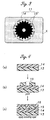
- Figure 1 is a plan view showing a first embodiment of the present invention including an identification medium 1 which is affixed generally to an object X or to a prescribed location thereof and consists of a single part or two or more parts, the object consisting of a card, passport, security note, gift certificate or the like.
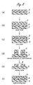
- the identification medium 1 is formed as a sticker by (a) coating high polymer cholesteric liquid crystal 4 over a base film 3, (b) applying a layer of resist 5 over the assembly, (c) photographically exposing the resist 5 by using a mask having a prescribed pattern as shown in Figure 1 and curing the resist, (d) etching away the part of the resist which has not cured and the high polymer cholesteric liquid crystal under it by using acid or alkaline chemicals such as nitric acid, hydrochloric acid and ammonium fluoride, (e) removing the remaining resist, and (f) generally applying a coating of a bonding agent or adhesive agent 6.
- the etching may also consist of dry etching using carbon tetrafluoride, for instance, instead of the wet etching using the above mentioned chemicals.
- the identification medium 1 in the form of a sticker is used with the base film 3 facing outward, and is affixed to the object X via the bonding agent or adhesive agent 6.
- the bonding agent or adhesive agent 6 has such a high mechanical strength that any attempt to peel off the sticker from the object X will result in the destruction of the high polymer cholesteric liquid crystal 4, thereby preventing the reuse of the sticker.
- the identification medium may also be formed directly on the surface of the object X by the steps of (a) to (e). If high polymer cholesteric liquid crystal 4 is applied to a base film 3 via a peel layer, and a hot melt layer is applied thereon following an etching process, the assembly can be used as a medium for hot stamping which is suitable for mass production. Hot stamping consists of a process by which an ornamental film is transferred onto the surface of an object by using instantaneous heat and pressure.
- FIG 3 is a plan view showing a second embodiment of the present invention including identification medium 11 which is affixed generally to the surface of an object X or to a prescribed location thereof and consists of one or a plurality of parts.
- the identification medium 11 is prepared in the form of a sticker by (a) coating high polymer cholesteric liquid crystal 14 over a base film 13, (b) printing a layer of ink 15 thereon according to a prescribed pattern as illustrated in Figure 3, and (c) generally applying a coating of a bonding agent or adhesive agent 16.
- the identification medium may be directly formed on the surface of the object X or may be formed as a medium for hot stamping.
- the high polymer cholesteric liquid crystal 14 and ink layer 15 may be directly formed on the object X, instead of on the base film 13, as was the case with the first embodiment, and the assembly may also be used as a medium for hot stamping.
- FIG. 5 is a plan view showing a third embodiment of the present invention including an identification medium 21 which is affixed generally to the surface of an object X or to a prescribed location thereof, and consists of one or a plurality of parts.
- an identification medium 21 which is affixed generally to the surface of an object X or to a prescribed location thereof, and consists of one or a plurality of parts.
- a layer of high polymer cholesteric liquid crystal 24 is formed into a desired shape as was done in the first embodiment, and a desired printing process is performed as was done in the second embodiment.
- Numeral 21a denotes a part which has been etched away
- numeral 21b denotes a part which is printed.
- FIG. 6 is a plan view showing a third embodiment of the present invention including an identification medium 31 which is affixed generally to the surface of an object X or to a prescribed location thereof.
- This identification medium 31 is a combination of three parts of high polymer cholesteric liquid crystal 34a, 34b and 34c having three different kinds of reflective wavelength selectivity and/or circularly polarizing reflective property of a specific direction (right or left).
- the medium may include three parts of high polymer cholesteric liquid crystal that reflect right circularly polarized light of three different colors, blue color for the letters 34a, red color for the central star-shaped region 34b and green color for the outer star-shaped region 34c.
- the surface of the object X is black in color, for instance, the patterns and letters in the three colors can be visually seen.
- the colors also change depending on the color of the surface of the object X and the color of the bonding agent.
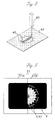
- the identification medium 31 is formed by transferring the three parts of high polymer cholesteric liquid crystal 34a, 34b and 34c having different properties supported by a ribbon onto the object X at a prescribed pattern as shown in Figure 7a. More specifically, as shown in Figure 7b, the ribbon 37 is formed by placing three parts of high polymer cholesteric liquid crystal on a base film 33 one next to the other, coating a bonding agent 36, and winding the assembly into a roll. Heat is applied to the ribbon by using a thermal head 38 of a thermal printer at a prescribed timing while the ribbon 37 is moved relative to the object X in the same way as in a known thermal printer. Thereby, desired parts of the high polymer cholesteric liquid crystal are peeled off from the base film 33, and are transferred upon the object X at the prescribed pattern.
- the process of transferring the corresponding parts of the high polymer cholesteric liquid crystal does not require a metallic die set or a master plate, and allows letters and shapes to be formed at will. In particular, a substantial saving in cost can be achieved when the production batches are small in quantity. By increasing the number of kinds of the high polymer cholesteric liquid crystal that are used, the number of available colors increases.
- letters and patterns 45 can also be drawn by scorching and discoloring selected parts of the high polymer cholesteric liquid crystal 44 by using a laser device 40. If the power of the laser is controlled, and the scorching process is conducted in a gradual manner, it is possible to change the pitch p (the distance required for each layer to twist by one turn) and change the color of the reflected light. Therefore, letters and patterns can be formed by the parts which are subjected to the laser and have thereby been made to reflect light of different colors.
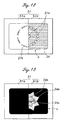
- the view obtained by a simple identification device 51 consisting of a left circularly polarizing filter 51a and a right circularly polarizing filter 51b placed one next to the other will be as given in Figure 9. More specifically, the right circularly polarizing filter 51b allows the image formed by the high polymer cholesteric liquid crystal 4 of the identification medium 1 that reflects only right circularly polarized light or the graphic pattern of the identification medium 1 to be transmitted or viewed.
- the left circularly polarizing filter 51a shuts off the graphic pattern of the identification medium 1 from view, and allows only the surface of the object X or the black background of the bonding agent 6 to be viewed. If the bonding agent 6 is transparent and a pattern is formed on the surface of the object X, the identification medium 1 appears semi-transparent, and the surface pattern and graphic pattern of the identification medium show dimly to the naked eye. However, the simple identification device 51 allows only the surface pattern to be viewed as shown in Figure 10 because the left circularly polarizing filter 51a shuts off the graphic pattern of the identification medium 1.
- the view obtained by the simple identification device 51 will be as given in Figure 11. More specifically, the right circularizing filter 51b transmits only the light reflected by the high polymer cholesteric liquid crystal 14 thereby making the ink 15 or printed image underlying the high polymer cholesteric liquid crystal 14 invisible while the left circularly polarizing filter 51a shuts off the light reflected by the high polymer cholesteric liquid crystal 14 thereby making only the printed image or the ink 15 underlying the high polymer cholesteric liquid crystal 14 visible.
- the view obtained by the simple identification device 51 will be as given in Figure 12. More specifically, the right circularizing filter 51b makes only the image etched out of the high polymer cholesteric liquid crystal 24 visible while the left circularly polarizing filter 51a shuts off the light reflected by the high polymer cholesteric liquid crystal 24 thereby making only the printed letters 21b visible.
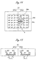
- the view obtained by a simple identification device 51 will be as shown in Figure 13 when the bonding agent is black and as shown in Figure 14 when the bonding agent is transparent.
- the pattern appears in the same way as the first embodiment illustrated in Figures 9 and 10, and only the colors are different.
- the identification device 61 consists of a pair identification units 61a and 61b.
- the identification unit 61a comprises a light source 62, a light receiving unit 63 and a right circularly polarizing filter 64 so that right circularly polarized light is impinged upon the object X and only right circularly polarized light is transmitted to the light receiving unit 63 while left circularly polarized light is shut off.
- the identification unit 61b comprises a light source 65, a light receiving unit 66 and a left circularly polarizing filter 67 so that left circularly polarized light is impinged upon the object X and only left circularly polarized light is transmitted to the light receiving unit 66 while right circularly polarized light is shut off.
- the light sources 62 and 65 preferably consist of light bulbs, LEDs or laser sources, but are not limited to them.
- the light receiving outputs from the light receiving units 63 and 66 of these identification units are given in Figures 16 for the cases of an identification medium consisting of high polymer cholesteric liquid crystal, a metallic vapor deposition layer tinted so as to have the appearance of high polymer cholesteric liquid crystal, and a combination of such a metallic vapor deposition layer and a film producing a phase delay of one-half the wavelength.
- the light receiving unit 63 of the identification unit 61a produces an output because the right circularly polarized light reflected by the high polymer cholesteric liquid crystal transmits through the right circularly polarizing filter 64 while the light receiving unit 66 of the identification unit 61b does not produce an output because left circularly polarized light is impinged upon the high polymer cholesteric liquid crystal, and no light is reflected therefrom.
- an output is obtained from the light receiving unit 63 because right circularly polarized light is not reversed by the metallic vapor deposition layer in the identification unit 61a and reflected as right circularly polarized light which in turn transmits through the right circularly polarizing filter 64. Similarly, an output is obtained from the light receiving unit 66.
- high polymer cholesteric liquid crystal when used, when a metallic vapor deposition layer is used, and when a combination of a metallic vapor deposition layer and a half-wavelength phase delay film is used, different kinds of output are obtained.
- the presence of high polymer cholesteric liquid crystal can be determined depending on if the received light output ratio (output from the light receiving unit 66 / output from the light receiving unit 63) is substantially zero or not. The authenticity can be therefore easily and accurately determined from the pattern (figures and patterns).
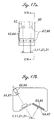
- Figures 17a and 17b show a possible actual structure of the identification device 61.
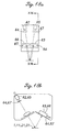
- Figures 18a and 18b show another possible actual structure of the identification device 61.
- the identification device 61 shown in Figures 17a and 17b includes the identification unit 61a and identification unit 61b which are arranged parallel to each other so as to identify two different points of an identification medium having a certain width, independently from each other.
- the identification device 61 shown in Figures 18a and 18b includes the identification unit 61a and identification unit 61b which are arranged in a mutually crossing relationship so as to impinge light upon a same point and simultaneously identify a same point of the identification medium. The latter case allows the size of the identification object to be minimized, and the identification reliability to be improved.
- the identification media described above may be formed on various cards, gift certificates and photographs of IDs and passports, and may also be formed into paper in the form of tape such as thread hologram.
Landscapes
- Physics & Mathematics (AREA)
- General Physics & Mathematics (AREA)
- Theoretical Computer Science (AREA)
- Engineering & Computer Science (AREA)
- Crystallography & Structural Chemistry (AREA)
- Chemical & Material Sciences (AREA)
- Marketing (AREA)
- Accounting & Taxation (AREA)
- Business, Economics & Management (AREA)
- Optics & Photonics (AREA)
- Polarising Elements (AREA)
- Credit Cards Or The Like (AREA)
- Duplication Or Marking (AREA)
- Liquid Crystal (AREA)
- Thermal Transfer Or Thermal Recording In General (AREA)
- Printing Methods (AREA)
Abstract
Description
Claims (10)
- An identification medium for identifying an authenticity of an object either visually or optically by using an identification device, characterized by that:the identification medium comprises high polymer cholesteric liquid crystal which is patterned and/or a graphic representation layer such as a figure and letter which underlies or overlies high polymer cholesteric liquid crystal.
- An identification medium according to claim 1, wherein the identification medium comprises high polymer cholesteric liquid crystal which is patterned by etching.
- An identification medium according to claim 1, wherein the identification medium comprises a printed layer underlying the high polymer cholesteric liquid crystal
- An identification medium according to claim 1, wherein the identification medium comprises high polymer cholesteric liquid crystal which is thermally transferred according to a prescribed pattern.
- An identification medium according to claim 1, wherein the identification medium comprises high polymer cholesteric liquid crystal which is partly modified by laser according to a prescribed pattern.
- A method for making an identification medium for identifying an authenticity of an object either visually or optically by using an identification device, characterized by the steps of:applying high polymer cholesteric liquid crystal onto the object, onto a sticker adapted to be affixed to the object or onto a base for hot stamping onto the object; andpatterning the high polymer cholesteric liquid crystal, and/or forming a graphic representation layer such as a figure and letter under or over the high polymer cholesteric liquid crystal.
- A method for making an identification medium according to claim 6, wherein the high polymer cholesteric liquid crystal is patterned by etching.
- A method for making an identification medium according to claim 6, wherein an ink layer underlying the high polymer cholesteric liquid crystal is formed by printing.
- A method for making an identification medium according to claim 6, wherein the high polymer cholesteric liquid crystal is thermally transferred onto the object, onto a sticker adapted to affixed to the object or onto a base for hot stamping onto the object according to a prescribed pattern.
- A method for making an identification medium according to claim 6, wherein the high polymer cholesteric liquid crystal is partly modified by laser according to a prescribed pattern.
Applications Claiming Priority (3)
| Application Number | Priority Date | Filing Date | Title |
|---|---|---|---|
| JP2000318779A JP2002127647A (en) | 2000-10-19 | 2000-10-19 | Object identification medium and method of manufacturing the same |
| JP2000318779 | 2000-10-19 | ||
| PCT/JP2001/009157 WO2002033453A1 (en) | 2000-10-19 | 2001-10-18 | Medium for identifying matter to be identified and method for production thereof |
Publications (2)
| Publication Number | Publication Date |
|---|---|
| EP1327895A1 true EP1327895A1 (en) | 2003-07-16 |
| EP1327895A4 EP1327895A4 (en) | 2005-08-31 |
Family
ID=18797354
Family Applications (1)
| Application Number | Title | Priority Date | Filing Date |
|---|---|---|---|
| EP01976743A Withdrawn EP1327895A4 (en) | 2000-10-19 | 2001-10-18 | IDENTIFICATION MEDIUM FOR MATERIAL IDENTIFYING AND CORRESPONDING PRODUCTION METHOD |
Country Status (4)
| Country | Link |
|---|---|
| US (1) | US6740431B2 (en) |
| EP (1) | EP1327895A4 (en) |
| JP (1) | JP2002127647A (en) |
| WO (1) | WO2002033453A1 (en) |
Cited By (8)
| Publication number | Priority date | Publication date | Assignee | Title |
|---|---|---|---|---|
| WO2005071497A1 (en) | 2004-01-19 | 2005-08-04 | David Ezra | Diffractive, polarization modulating optical devices |
| WO2005108107A1 (en) * | 2004-04-30 | 2005-11-17 | Giesecke & Devrient Gmbh | Security element and method for producing said element |
| WO2005108108A3 (en) * | 2004-04-30 | 2006-04-06 | Giesecke & Devrient Gmbh | Security element and methods for the production thereof |
| WO2007140887A3 (en) * | 2006-06-09 | 2008-03-27 | Giesecke & Devrient Gmbh | Security element |
| EP1523416A4 (en) * | 2002-06-18 | 2009-12-02 | Securency Int Pty Ltd | Polarising liquid crystal device for security documents |
| US7808605B2 (en) | 2004-04-30 | 2010-10-05 | Giesecke & Devrient Gmbh | Sheeting and methods for the production thereof |
| WO2011057759A1 (en) * | 2009-11-11 | 2011-05-19 | Giesecke & Devrient Gmbh | Method for producing a security element having registered metallized parts and security element obtainable therefrom |
| US8684415B2 (en) | 2006-05-26 | 2014-04-01 | De La Rue International Limited | Substrates |
Families Citing this family (48)
| Publication number | Priority date | Publication date | Assignee | Title |
|---|---|---|---|---|
| US6479118B1 (en) * | 2000-05-04 | 2002-11-12 | Fellowes Inc. | Foldable die cut self-adhesive label sheet for labeling CD-ROMS |
| US7625619B2 (en) * | 2000-09-29 | 2009-12-01 | Avery Dennison Corporation | Label sheet construction |
| US7057687B2 (en) * | 2001-03-30 | 2006-06-06 | Dai Nippon Printing Co., Ltd. | Method of patterning cholesteric film using a laser and optical element having the cholesteric film patterned by the method |
| USD514164S1 (en) * | 2001-09-17 | 2006-01-31 | Avery Dennison Corporation | Self-adhesive label |
| US7030972B2 (en) * | 2002-02-12 | 2006-04-18 | Xerox Corporation | System and method for identifying objects |
| JP2003231380A (en) * | 2002-02-12 | 2003-08-19 | Nhk Spring Co Ltd | Object identification medium and identification method |
| US20050213078A1 (en) * | 2002-04-04 | 2005-09-29 | Landqart | Device for checking security elements |
| JP4033864B2 (en) * | 2002-09-30 | 2008-01-16 | 大阪シーリング印刷株式会社 | Liquid crystal label having re-sticking prevention function, liquid crystal label continuous body, and production method thereof |
| JP4079748B2 (en) * | 2002-10-22 | 2008-04-23 | 大阪シーリング印刷株式会社 | Liquid crystal laminate and liquid crystal laminate continuum |
| US9856402B2 (en) | 2003-01-22 | 2018-01-02 | Ccl Lavel, Inc. | Adhesive label liner sheet modifications for retaining unneeded label sections on liner |
| DE10328741A1 (en) * | 2003-06-25 | 2005-01-13 | Metronic Ag | Method and printed product for generating freely programmable printed images |
| EP1698194A1 (en) * | 2003-12-23 | 2006-09-06 | Electronics And Telecommunications Research Institute | Apparatus and method for testing and analyzing base station with smart antenna, and protocol structure |
| US20070081144A1 (en) | 2003-12-26 | 2007-04-12 | Nhk Spring Co., Ltd. | Discrimination medium and discrimination method for discriminating the same |
| JP4684560B2 (en) * | 2004-01-28 | 2011-05-18 | 大阪シーリング印刷株式会社 | Lcd label |
| USD505699S1 (en) * | 2004-03-16 | 2005-05-31 | Finished Art, Inc. | Retail shelving label |
| US7292321B2 (en) * | 2004-04-27 | 2007-11-06 | Matsushita Electric Industrial Co., Ltd. | Contact detection sensor and contact detection method |
| US20070246933A1 (en) * | 2004-08-12 | 2007-10-25 | Giesecke & Devrient Gmbh | Security Element Comprising a Support |
| TW200641784A (en) * | 2005-05-27 | 2006-12-01 | Phison Electronics Corp | Electronic product with data display |
| US7909364B2 (en) * | 2005-09-07 | 2011-03-22 | Dai Nippon Printing Co., Ltd. | Indicator for indicating authenticity |
| JP4693125B2 (en) * | 2006-10-11 | 2011-06-01 | 大阪シーリング印刷株式会社 | Sheet member with liquid crystal and method for producing the same |
| JP4959304B2 (en) | 2006-11-22 | 2012-06-20 | 日本発條株式会社 | Identification medium, identification method, and identification apparatus |
| JP2011519066A (en) | 2008-04-24 | 2011-06-30 | エイベリ・デニソン・コーポレイション | Peelable label sheet and related method |
| JP5540473B2 (en) * | 2008-06-12 | 2014-07-02 | 凸版印刷株式会社 | Cholesteric liquid crystal display supplies |
| JP5451235B2 (en) | 2009-07-31 | 2014-03-26 | 富士フイルム株式会社 | Method for producing article having birefringence pattern and birefringence pattern builder |
| JP5307663B2 (en) * | 2009-08-24 | 2013-10-02 | 富士フイルム株式会社 | Reproduction image reading method and reproduction image reading apparatus |
| JP2010079308A (en) * | 2009-11-30 | 2010-04-08 | Dainippon Printing Co Ltd | Medium for determining authenticity, medium label for determining authenticity, medium transfer sheet for determining authenticity, sheet determining authenticity, and information recording medium determining authenticity |
| JP5059167B2 (en) * | 2010-06-03 | 2012-10-24 | 大阪シーリング印刷株式会社 | Liquid crystal label continuum |
| USD687857S1 (en) * | 2011-12-02 | 2013-08-13 | Microsoft Corporation | Display screen with icon |
| JP6128749B2 (en) * | 2012-04-18 | 2017-05-17 | 日本発條株式会社 | Optical reader, optical reading method and program |
| US9279927B2 (en) | 2013-02-15 | 2016-03-08 | Opsec Security Group, Inc. | Security device having optically variable device portion and method of making the same |
| JP2013226835A (en) * | 2013-04-26 | 2013-11-07 | Dainippon Printing Co Ltd | Medium for determining authenticity, medium label for determining authenticity, medium transfer sheet for determining authenticity, sheet capable of determining authenticity, and information recording body capable of determining authenticity |
| JP6220213B2 (en) * | 2013-10-04 | 2017-10-25 | 旭化成株式会社 | Polarizing member, spectacle lens, and patterned sunglasses |
| JP6165018B2 (en) * | 2013-10-11 | 2017-07-19 | 旭化成株式会社 | Polarizing member, spectacle lens, polarized sunglasses, and combiner |
| US9852661B2 (en) | 2015-02-20 | 2017-12-26 | Ccl Label, Inc. | Self laminating labels |
| WO2017009494A1 (en) * | 2015-07-10 | 2017-01-19 | Universidad Politecnica De Madrid | Method and device for achieving document security by generating multiple reflexive and transmissive latent images |
| US11049420B2 (en) | 2016-11-15 | 2021-06-29 | Ccl Label, Inc. | Label sheet assembly with surface features |
| USD841087S1 (en) | 2016-11-17 | 2019-02-19 | Ccl Label, Inc. | Label sheet with a feed edge assembly |
| WO2018146995A1 (en) | 2017-02-08 | 2018-08-16 | 富士フイルム株式会社 | Decorative film |
| USD813944S1 (en) | 2017-03-13 | 2018-03-27 | Ccl Label, Inc. | Label sheet assembly |
| USD853480S1 (en) | 2017-05-10 | 2019-07-09 | Ccl Label, Inc. | Label sheet assembly |
| USD856414S1 (en) | 2018-03-01 | 2019-08-13 | Ccl Label, Inc. | Label sheet assembly with feed edge dress |
| US11279162B2 (en) | 2018-03-01 | 2022-03-22 | Ccl Label, Inc. | Sheet with feeding perforation |
| USD893606S1 (en) | 2018-03-23 | 2020-08-18 | Ccl Label, Inc. | Name badge sheet assembly |
| USD877241S1 (en) | 2018-06-08 | 2020-03-03 | Ccl Label, Inc. | Label sheet layout assembly |
| USD914085S1 (en) | 2018-08-29 | 2021-03-23 | Ccl Label, Inc. | Label sheet layout assemblies |
| USD943668S1 (en) | 2019-05-01 | 2022-02-15 | Ccl Label, Inc. | Label sheet with surface texture assembly |
| USD915461S1 (en) * | 2019-08-27 | 2021-04-06 | Star Co Scientific Technologies Advanced Research Co, Llc | Display screen or portion thereof with icon |
| US11605313B2 (en) | 2020-07-02 | 2023-03-14 | Ccl Label, Inc. | Label sheet assembly with puncture surface features |
Family Cites Families (26)
| Publication number | Priority date | Publication date | Assignee | Title |
|---|---|---|---|---|
| US4536014A (en) * | 1981-01-08 | 1985-08-20 | Securicard Systems Limited | Indentification of articles using liquid crystal identity cards |
| JPS6351193A (en) * | 1986-08-21 | 1988-03-04 | 日石三菱株式会社 | Card for preventing forgery |
| DE3942663A1 (en) * | 1989-12-22 | 1991-06-27 | Gao Ges Automation Org | DATA CARRIER WITH A LIQUID CRYSTAL SECURITY ELEMENT |
| GB9106128D0 (en) * | 1991-03-22 | 1991-05-08 | Amblehurst Ltd | Article |
| GB2268906A (en) * | 1992-07-24 | 1994-01-26 | Portals Ltd | Counterfeit protection for documents using optical effects of liquid crystal |
| FR2698390B1 (en) * | 1992-11-20 | 1994-12-23 | Arjo Wiggins Sa | Security document authenticated by piezooptic effect. |
| JPH06351193A (en) | 1993-06-02 | 1994-12-22 | Hitachi Ltd | AC generator with vacuum pump |
| DE69415547T2 (en) * | 1993-09-28 | 1999-08-19 | Minnesota Mining And Mfg. Co. | SECURITY CARD AND THEIR PRODUCTION PROCESS |
| US5629055A (en) * | 1994-02-14 | 1997-05-13 | Pulp And Paper Research Institute Of Canada | Solidified liquid crystals of cellulose with optically variable properties |
| US5857709A (en) * | 1997-02-24 | 1999-01-12 | Chock; Ernest P. | Anticounterfeit documentation with see-through and write-able hologram |
| JP3652487B2 (en) * | 1997-11-20 | 2005-05-25 | 日本発条株式会社 | Medium for identifying object, identification structure and identification method |
| EP0911758B1 (en) * | 1997-07-29 | 2005-11-30 | Nhk Spring Co.Ltd. | Optical identification system using cholesteric liquid crystals |
| JP3652476B2 (en) * | 1997-07-29 | 2005-05-25 | 日本発条株式会社 | Object identification structure and object provided with the structure |
| DE19737618A1 (en) * | 1997-08-28 | 1999-03-04 | Consortium Elektrochem Ind | Machine-detectable security marking with increased protection against forgery, production of the security marking and security system comprising this security marking |
| DE19737612A1 (en) * | 1997-08-28 | 1999-03-04 | Consortium Elektrochem Ind | Machine-detectable security marking, production of the security marking and security system that cannot be recognized by the eye and encompass this security marking |
| JP3689237B2 (en) * | 1998-03-27 | 2005-08-31 | 日本発条株式会社 | Object identification structure |
| JP4278731B2 (en) | 1998-07-09 | 2009-06-17 | 大日本印刷株式会社 | Authenticator and its usage |
| JP4336008B2 (en) * | 1998-11-17 | 2009-09-30 | 日本発條株式会社 | Object identification structure and identification method |
| JP4335352B2 (en) * | 1999-03-05 | 2009-09-30 | 大日本印刷株式会社 | Anti-counterfeit body and forgery discrimination method |
| JP2000318399A (en) | 1999-05-07 | 2000-11-21 | Toppan Printing Co Ltd | Anti-counterfeit paper |
| KR100675997B1 (en) | 1999-07-02 | 2007-01-29 | 메르크 파텐트 게엠베하 | Manufacturing method of multilayer cholesteric film |
| JP2001105800A (en) | 1999-08-04 | 2001-04-17 | Toppan Printing Co Ltd | Method for preventing forgery of image receiving sheet, image receiving sheet provided with forgery prevention, and image display using the same |
| JP3342445B2 (en) | 1999-08-30 | 2002-11-11 | ポリマテック株式会社 | Decorative key top and method of manufacturing the same |
| JP2001232978A (en) * | 2000-02-24 | 2001-08-28 | Toppan Printing Co Ltd | Passport having latent image, method of manufacturing the same, and method of verifying the passport |
| JP2001246886A (en) | 2000-03-07 | 2001-09-11 | Fuji Photo Film Co Ltd | Information indicating material having properties of authentication and method of discriminating authentication |
| JP2001242748A (en) | 2000-12-11 | 2001-09-07 | Canon Inc | Image forming device |
-
2000
- 2000-10-19 JP JP2000318779A patent/JP2002127647A/en active Pending
-
2001
- 2001-10-18 EP EP01976743A patent/EP1327895A4/en not_active Withdrawn
- 2001-10-18 US US10/168,192 patent/US6740431B2/en not_active Expired - Fee Related
- 2001-10-18 WO PCT/JP2001/009157 patent/WO2002033453A1/en not_active Ceased
Cited By (10)
| Publication number | Priority date | Publication date | Assignee | Title |
|---|---|---|---|---|
| EP1523416A4 (en) * | 2002-06-18 | 2009-12-02 | Securency Int Pty Ltd | Polarising liquid crystal device for security documents |
| WO2005071497A1 (en) | 2004-01-19 | 2005-08-04 | David Ezra | Diffractive, polarization modulating optical devices |
| US7679826B2 (en) | 2004-01-19 | 2010-03-16 | De Technologies Limited | Diffractive, polarization modulating optical devices |
| WO2005108107A1 (en) * | 2004-04-30 | 2005-11-17 | Giesecke & Devrient Gmbh | Security element and method for producing said element |
| WO2005108108A3 (en) * | 2004-04-30 | 2006-04-06 | Giesecke & Devrient Gmbh | Security element and methods for the production thereof |
| US7808605B2 (en) | 2004-04-30 | 2010-10-05 | Giesecke & Devrient Gmbh | Sheeting and methods for the production thereof |
| EP1744900B1 (en) | 2004-04-30 | 2016-07-20 | Giesecke & Devrient GmbH | Security element and methods for the production thereof |
| US8684415B2 (en) | 2006-05-26 | 2014-04-01 | De La Rue International Limited | Substrates |
| WO2007140887A3 (en) * | 2006-06-09 | 2008-03-27 | Giesecke & Devrient Gmbh | Security element |
| WO2011057759A1 (en) * | 2009-11-11 | 2011-05-19 | Giesecke & Devrient Gmbh | Method for producing a security element having registered metallized parts and security element obtainable therefrom |
Also Published As
| Publication number | Publication date |
|---|---|
| EP1327895A4 (en) | 2005-08-31 |
| JP2002127647A (en) | 2002-05-08 |
| WO2002033453A1 (en) | 2002-04-25 |
| US6740431B2 (en) | 2004-05-25 |
| US20030133098A1 (en) | 2003-07-17 |
Similar Documents
| Publication | Publication Date | Title |
|---|---|---|
| US6740431B2 (en) | Medium for identifying matter to be identified and method for production thereof | |
| JP7383235B2 (en) | Information display medium and related manufacturing method | |
| US6975765B2 (en) | Optically variable form birefringent structure and method and system and method for reading same | |
| CN101687426B (en) | Multi-layer body | |
| JP4257903B2 (en) | Identification medium, identification medium identification method, identification target article, and identification apparatus | |
| CN1630892B (en) | Identifying medium and identifying method for object | |
| CN107921811A (en) | Safety device and its manufacture method | |
| US20080204876A9 (en) | Form birefringent grating structure, viewer, anticounterfeit security device, and method for making the same | |
| CN102667580A (en) | Identification medium and identification method therefore | |
| EP0911758A2 (en) | Optical identification system using cholesteric liquid crystals | |
| JP2009172798A (en) | Identification medium and manufacturing method thereof | |
| CN101848815A (en) | Improvements in security devices | |
| CN101454165A (en) | Improvements in substrates | |
| JP4924087B2 (en) | INTERMEDIATE TRANSFER RECORDING MEDIUM, INFORMATION RECORDING METHOD USING THE SAME, INFORMATION RECORDING MANUFACTURING METHOD, AND AUTHENTICITY JUDGING METHOD | |
| EP3114279B1 (en) | Method of forming a security document | |
| JP4236853B2 (en) | Authenticity judgment system | |
| JP2000242748A (en) | Authenticity identification method, authenticity identification body and method of manufacturing the same | |
| JP7496837B2 (en) | Optical security component having a plasmonic effect, manufacture of such a component, security object equipped with such a component - Patents.com | |
| JP5082378B2 (en) | Display and printed matter | |
| JP5163039B2 (en) | Anti-counterfeit structure, anti-counterfeit single body using the same, and authenticity determination method thereof | |
| JP4669545B2 (en) | Authenticity discriminator, authenticity discrimination method, and authenticity discriminator manufacturing method | |
| CN110908265B (en) | Structure for enhancing endorsement image effect, anti-counterfeiting card and endorsement method | |
| JP4550235B2 (en) | Authenticator | |
| JPWO2017204168A1 (en) | Anti-counterfeit media | |
| JP2004053870A (en) | Anti-counterfeit thread and anti-counterfeit paper |
Legal Events
| Date | Code | Title | Description |
|---|---|---|---|
| PUAI | Public reference made under article 153(3) epc to a published international application that has entered the european phase |
Free format text: ORIGINAL CODE: 0009012 |
|
| AK | Designated contracting states |
Designated state(s): AT BE CH CY DE DK ES FI FR GB GR IE IT LI LU MC NL PT SE TR |
|
| AX | Request for extension of the european patent |
Extension state: AL LT LV MK RO SI |
|
| RBV | Designated contracting states (corrected) |
Designated state(s): AT BE CH CY DE FR GB LI NL SE |
|
| A4 | Supplementary search report drawn up and despatched |
Effective date: 20050715 |
|
| RIC1 | Information provided on ipc code assigned before grant |
Ipc: 7G 09F 3/00 B Ipc: 7G 09F 3/02 B Ipc: 7B 44F 1/12 B Ipc: 7G 01D 7/12 B Ipc: 7B 42D 15/10 B Ipc: 7G 09F 19/12 B Ipc: 7G 02B 5/30 A |
|
| 17P | Request for examination filed |
Effective date: 20030523 |
|
| STAA | Information on the status of an ep patent application or granted ep patent |
Free format text: STATUS: THE APPLICATION IS DEEMED TO BE WITHDRAWN |
|
| 18D | Application deemed to be withdrawn |
Effective date: 20090106 |