EP1327837A2 - Automatic cooling agent valve - Google Patents
Automatic cooling agent valve Download PDFInfo
- Publication number
- EP1327837A2 EP1327837A2 EP02445185A EP02445185A EP1327837A2 EP 1327837 A2 EP1327837 A2 EP 1327837A2 EP 02445185 A EP02445185 A EP 02445185A EP 02445185 A EP02445185 A EP 02445185A EP 1327837 A2 EP1327837 A2 EP 1327837A2
- Authority
- EP
- European Patent Office
- Prior art keywords
- liquid
- valve device
- valve
- cooling
- chamber
- Prior art date
- Legal status (The legal status is an assumption and is not a legal conclusion. Google has not performed a legal analysis and makes no representation as to the accuracy of the status listed.)
- Granted
Links
Images

Classifications
-
- F—MECHANICAL ENGINEERING; LIGHTING; HEATING; WEAPONS; BLASTING
- F25—REFRIGERATION OR COOLING; COMBINED HEATING AND REFRIGERATION SYSTEMS; HEAT PUMP SYSTEMS; MANUFACTURE OR STORAGE OF ICE; LIQUEFACTION SOLIDIFICATION OF GASES
- F25B—REFRIGERATION MACHINES, PLANTS OR SYSTEMS; COMBINED HEATING AND REFRIGERATION SYSTEMS; HEAT PUMP SYSTEMS
- F25B25/00—Machines, plants or systems, using a combination of modes of operation covered by two or more of the groups F25B1/00 - F25B23/00
- F25B25/005—Machines, plants or systems, using a combination of modes of operation covered by two or more of the groups F25B1/00 - F25B23/00 using primary and secondary systems
-
- F—MECHANICAL ENGINEERING; LIGHTING; HEATING; WEAPONS; BLASTING
- F28—HEAT EXCHANGE IN GENERAL
- F28D—HEAT-EXCHANGE APPARATUS, NOT PROVIDED FOR IN ANOTHER SUBCLASS, IN WHICH THE HEAT-EXCHANGE MEDIA DO NOT COME INTO DIRECT CONTACT
- F28D15/00—Heat-exchange apparatus with the intermediate heat-transfer medium in closed tubes passing into or through the conduit walls ; Heat-exchange apparatus employing intermediate heat-transfer medium or bodies
- F28D15/02—Heat-exchange apparatus with the intermediate heat-transfer medium in closed tubes passing into or through the conduit walls ; Heat-exchange apparatus employing intermediate heat-transfer medium or bodies in which the medium condenses and evaporates, e.g. heat pipes
- F28D15/06—Control arrangements therefor
-
- F—MECHANICAL ENGINEERING; LIGHTING; HEATING; WEAPONS; BLASTING
- F25—REFRIGERATION OR COOLING; COMBINED HEATING AND REFRIGERATION SYSTEMS; HEAT PUMP SYSTEMS; MANUFACTURE OR STORAGE OF ICE; LIQUEFACTION SOLIDIFICATION OF GASES
- F25B—REFRIGERATION MACHINES, PLANTS OR SYSTEMS; COMBINED HEATING AND REFRIGERATION SYSTEMS; HEAT PUMP SYSTEMS
- F25B2600/00—Control issues
- F25B2600/25—Control of valves
- F25B2600/2515—Flow valves
Definitions
- the present invention relates a valve device for a cooling agent circuit, which circuit comprises a closed pipe loop with cooling agent and which pipe loop at least partly passes through a first liquid.
- Some food products need to be stored at a specific temperature that differs from the normal temperature of a cooling cabinet, such as a refrigerator cabinet. Meat for example should be stored at approximately zero degrees Celsius, which storage leads to a considerably extended storage time for the food product without needing to freeze it.
- US5212962 discloses one embodiment of a cooling device for a refrigerator cabinet.
- the document describes a device in which air is circulated in a lower compartment in order to achieve an even, low temperature for vegetables.
- a fan brings the air to circulation and two sensors detect the temperature in each space. If the temperature in the lower space exceeds a certain value the fan starts rotating and the circulating air brings the temperature down.
- US4539819 discloses a similar cooling device. Air circulates in a space below a storage box intended to store meat. A fan unit regulates the airflow and controls that the temperature in the box is kept at an adequate temperature.
- the cooling devices can only be used in refrigerators with an air circulation system. Moreover, the devices are depended on the functionality of the fan unit and the sensors. If the system should fail the temperature will change rapidly in the cooling device. Furthermore, it is difficult to achieve a temperature for example around zero degrees Celsius for meat, which is necessary in order to increase the storage time. Another problem occurring is that such cooling devices require a cabinet adapted for the device.
- the cooling device which is detachably arranged against the cooling surface inside a compressor-cooling refrigerator, comprises a cooling agent circuit comprising a closed pipe loop.
- a cabinet in the device encloses a volume, inside which food products can be stored. At least one of the walls enclosing the volume is at least partly filled with a liquid with a well-defined freezing point.
- Water is a suitable liquid for a device intended to achieve a zero degree storage volume.
- a first part of the pipe loop extends through the liquid and a second part extends in contact with the cooling surface of a refrigerator. The contact with the surface brings cooling energy to the cooling agent which makes it circulate in the cooling agent circuit.
- a valve manually operated by the user, regulates the flow of agent. The valve is adjusted based on information about the temperature in different areas and settings on the refrigerator thermostat, which adjustments stabilizes the temperature inside the volume.
- the object of the present invention is therefore to achieve a valve for a cooling device, which stabilizes the temperature of the cooling device volume at the specific temperature.
- the valve should also be easy to produce, cheap and be able to attach to a cooling agent system as the ones used in the cooling device.
- the valve should be reliable and consist of simple, standards components. It shall moreover be able to handle the pressure and temperature conditions that may occur.
- Fig. 1 shows a valve device according to the present invention with a cross section of the valve house.
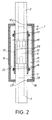
- Fig. 2 shows the valve device according to fig. 1 with a cross section also comprising the valve tube of the device with accompanying attachments.
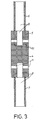
- Fig. 3 shows a cross section of the valve tube according to fig. 1 -2.
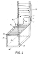
- Fig 4 shows a pespective view a a cooling device at which the valve device according to claim 1 can be attached.
- the valve device 1 is in use attached to a cooling agent circuit 30 (fig. 4) at the two ends 2,3 of the closed pipe loop.
- fig. 2 it is shown how the circuit is attached to a mouthpiece 4 as part of the valve device.
- the mouthpiece is shown in detail in fig. 3.
- the mouthpiece and the connections are preferably made in one piece in a metal that is chemically stable in contact with the metal of pipe of the cooling circuit.
- the connections are adapted to the diameter of the pipe ends 2,3, normally 6,5 millimetres, in order for the ends to fit outside the mouthpiece connections 6,7. It is necessary that the fit is as tight as possible.
- the fit may be made by gluing welding.
- passage 8,9 in each one of the mouthpiece 4 connections 6,7.
- the passages extend in parallel with each other in the longitudinal direction of the connections, from the outer ends of the connections into the mouthpiece without coming into contact with each other.
- the inner diameter of the passages is in this embodiment larger inside the mouthpiece connections. This is not necessary.
- Valve passages 10,11 connect the inner side with the passages 8,9 with openings on the envelope surface of the mouthpiece. In fig. 3 there are two valve passages 10,11 per side but it is of course possible to have more such passages.
- FIG. 2 the mouthpiece 4 is shown attached by the connections 10,11 and the pipe ends 2,3 to the cooling agent circuit 30.
- the connections 6,7 are visible.
- a valve tube 12 is mounted around the mouthpiece.
- FIG. 1 the outside of the valve tube is shown and fig. 2 shows the cross section of the tube.
- Fig. 2 also shows the cross section of two attachments 13,14 that seals the ends of the tube against the pipe ends 2,3 in order to achieve a sealed chamber 23 between the tube and the mouthpiece. Since the inner diameter of the tube, which corresponds to the outer diameter of the circuit pipe 2,3, is larger than the outer diameter of the mouthpiece 4 the chamber is formed. The chamber stretches all the way around the mouthpiece.
- the valve tube is formed in an elastic material that should be chemically and mechanically stable in connection with other materials or liquids. Its shape is circular in order to fit the pipe ends of the cooling agent circuit.
- the valve house 15 encloses the mouthpiece 4 and the valve tube 12.
- the task of the valve house is essential for the valve device.
- the house is in the embodiment circular and made in metal, which results in that the house behaves non-elastic when exposed to high pressure.
- the house must be tight in high-pressure situations, whereby the contact surfaces 16,17 between the house and the circuit pipes 2,3 are preferably joined together by gluing or welding.
- an end part 18 is finally mounted on the house.
- a first chamber 19 formed between the valve house 15, the valve tube 12 and the circuit pipes 2,3 is filled with two liquids 20,21.
- the liquids should have different properties.
- a first one of the liquids 20 should have a freezing point similar with the freezing point of the liquid in the cooling device that the valve device 1 intends to be used together with.
- the cooling device will be further described down below. No organic material should be able to grow inside the liquid and the liquid should not be human or environmental unfriendly.
- the first liquid 20 fills the lower part of the first chamber up to a surface 22.
- the liquid should not surround any of the valve passages 11.
- a second liquid 21 fills the rest of the first chamber and surrounds the whole valve mouthpiece 4 and one of the connections 6,7.
- the second liquid should not be mixable with the first liquid.
- the second liquid should have a density that essentially diverges from the density of the first liquid and have a freezing point at least lower than 20 degrees Celsius.
- a suitable second liquid could be silicon oil.
- the valve device 1 should fulfil the following requirement:
- the valve house 15 should be able to cope the pressure rise when the first liquid 20 expands (the second liquid has a very low freezing point), which corresponds to the fact that the liquid freezes to ice. Water for example expands 8% when it freezes.
- the volume of the sealed chamber 23 should be smaller that the increasing volume of the freezing liquid 20.
- the density of the second liquid 21 should further on essentially differ from the density of the first liquid when the first liquid has expanded to its full range.
- a little air bubble may be arranged together with the liquids in the first chamber in order to avoid a critical pressure increase in the valve house when the first liquid freezes.
- An alternative to the bubble is to design the valve house in an elastic material.
- the cooling agent circuit 30 comprises a closed pipe loop.
- a first part 31 of the pipe loop passes through a circuit liquid inside the wall side 32, which liquid has properties that corresponds to the properties of the first liquid 20 of the valve device. More walls 36 cooperate to enclose a volume 35 that is cooled by the circuit liquid.
- a second part 33 of the pipe loop is arranged at a cooling surface (not shown), whereby a low thermal resistance is achieved between the pipe and the surface. The cooling surface thereby transfers cooling energy that brings the cooling agent in the closed pipe loop to circulate.
- a second valve 34 is attached to the cooling agent circuit that only allows the agent to flow in one direction.
- the agent will flow from the lower pipe end 3 towards the passage 9.
- the agent will then moves via the valve passage 11, the sealed chamber 23 through the valve passage 10.
- the cooling agent is thereafter forced through the passage 8 into the closed pipe loop through the pipe end 2.
- the flowing, circulating cooling agent will transfer cooling energy that cools the circuit liquid.
- the agent temperature therefore rises and the agent is vaporized which causes it to rise inside the closed pipe and moves upward.
- the valve 34 forces the agent in one direction through the valve device 1, whereby the agent in the second part 33 receives cooling agent and again is liquefied.
- the liquefied agent flows back downward through the second valve 34 to the circuit liquid and transfers more cooling agent to the circuit liquid inside the wall 32. This causes the circuit liquid to finally start freezing to ice.
- the cooled liquid transfers cooling energy to the volume 35 and the temperature of the air inside the volume follows the temperature of the circuit liquid.
- the temperature of the circuit liquid sinks the temperature of the flowing agent also goes down.
- the temperature of the liquids inside the valve therefore follows the temperature of the circuit liquid and the volume 35. Since the circuit liquid and the first liquid 20 have the same freezing point, the first liquid starts freezing to ice when the circuit liquid starts freezing. And since liquids freezing to ice, preferably water, expands when it freezes the pressure inside the valve house 15 will start rising. The valve house behaves non-elastic, and if there is an air bubble this will be compressed. The liquid therefore expands towards the valve tube 12, which is compressed. This causes the volume of the sealed chamber 23 to decrease therefore the flow of the agent will decrease.
- the first liquid 20 will freeze to ice since the freezing point of the second liquid 21 is much lower. Since the first liquid does not surround the valve tube 12 around the sealed chamber 23, no ice will hinder the valve tube from being compressed. The compression of the chamber decreases the agent flow and the temperature of the circuit liquid and will start rising, since it receives less cooling energy. The temperature of the agent thereby rises again, which causes the temperature of the liquids 20,21 in the valve device to rise. This results in that the ice of the first liquid 20 starts melting. The pressure inside the valve house thereby goes down and the cooling agent flow increase. The increased flow causes more cooling energy to be transferred to the circuit liquid, whereby the temperature goes down again. This mechanism will cause the temperature of the circuit liquid to oscillate around its freezing point, which for water is around zero degrees Celsius. The temperature of the cooling device volume 35 will thereby substantially stabilize around the freezing point of the cooling liquid.
- valve device 1 All parts of the valve device 1 have to cooperate in order for it to work.
- the relation between different volumes and selection of materials much be set depending on how pressure and temperature intends to work together. If the volume increase is too large in relation to the sealed chamber 23, the flow will be decreased too much. Moreover, a large overpressure will rise inside the valve device, which will cause problems.
- the construction also has to take the laws of thermodynamics into consideration.
- the valve device is mainly intended to be used together with the cooling device as shown above and fig. 4.
- the cooling device comprises a cabinet with isolated walls 36, where at least one wall 32 is being filled with the circuit liquid.
- the valve device 1 automatically regulates the agent flow in the device circuit in order for the liquid to stabilize its temperature around the freezing point, zero degrees Celsius for water.
- the cooling device is detachably placed against a cooling surface in order to receive cooling energy for its function. It is thereby achieved a cooling cabinet with a compartment inside which food products needing a storage temperature around the freezing point of the circuit liquid.
Landscapes
- Engineering & Computer Science (AREA)
- Physics & Mathematics (AREA)
- Mechanical Engineering (AREA)
- Thermal Sciences (AREA)
- General Engineering & Computer Science (AREA)
- Life Sciences & Earth Sciences (AREA)
- Sustainable Development (AREA)
- Temperature-Responsive Valves (AREA)
- Devices That Are Associated With Refrigeration Equipment (AREA)
- Cooling Or The Like Of Electrical Apparatus (AREA)
- Details Of Valves (AREA)
Abstract
Description
Claims (18)
- Valve device (1) for a cooling agent circuit (30), which circuit comprises a closed pipe loop with cooling agent and which pipe loop at least partly passes through a first liquid, characterized in, that the valve device (1) comprises means for regulating the temperature of the first liquid by adjusting the flow of cooling agent in the circuit (30), which regulation depends on the temperature of the cooling agent at the valve device (1).
- Valve device (1) according to claim 1 characterized in that the valve device (1) comprises two connections (6,7), each one having a passage (8,9) inside, which connections are adapted in order to achieve a substantially tight connection with pipe ends (2,3) of the pipe loop.
- Valve device (1) according to any of the preceding claims characterized in that the valve device (1) comprises a mouthpiece (4) in its both ends has having passages (8,9) extending substantially in parallel with each other in the longitudinal direction of the mouthpiece (4) without being connected to each other, which passages (8,9) at its inner ends have valve passages (10,11) connecting the cooling agent circuit with openings on the envelope surface of the mouthpiece.
- Valve device (1) according to both claims 2 - 3 characterized in that the connections (6,7) and the mouthpiece are made in one piece with the same centre axis, which passages (8,9,19,11) connects the two pipe ends (2,3) with each other.
- Valve device (1) according to both claims 3 - 4 characterized in that the device comprises a regulation part having a valve tube (12) surrounding parts of the mouthpiece (4) and the pipe ends (2,3) and a valve house (15) surrounding the valve tube (12).
- Valve device (1) according to claim 5 characterized in that a sealed chamber (23) is enclosed substantially by the valve tube (12) and the mouthpiece, which chamber (23) is sealed by attachments (13,14) in both ends of the tube (12).
- Valve device (1) according to any of the claims 5 - 6 characterized in that a first chamber (19) substantially enclosed by the valve house (15) and the valve tube (12) is at least partly filled with a second liquid (20).
- Valve device (1) according to claim 7 characterized in that the second liquid (20 ) together with a third liquid (21), not mixable with the second liquid (20), together substantially fills the first chamber (19), which third liquid (21) has a freezing point that is substantially lower than the freezing point of the second liquid (20) and a density which substantially differs from the density of the second liquid (20).
- Valve device (1) according to claim 8 characterized in that the third liquid (21) substantially surrounds the whole mouthpiece (4).
- Valve device according to any of the claims 7 - 9 characterized in that the second liquid (20) is water-based and has a freezing point around zero degrees Celsius.
- Valve device according to any of the claims 7 - 10 characterized in that the second liquid (20) has a freezing point that is similar with the freezing point of the first liquid.
- Valve device according to any of the claims 7 - 11 characterized in that the volume of the second chamber (23) is less than or equal with the change of volume of the second (20) when it freezes and expands.
- Valve device according to any of the claims 7 - 12 characterized in that the valve house (15) is designed to substantially seal the first chamber (19) and keep its volume substantially constant despite pressure changes inside the chamber.
- Valve device according to any of the claims 7 - 12 characterized in that the valve house (15) is designed to substantially seal the first chamber (19) and enable its volume to change depending on the pressure changes inside the chamber (19).
- Use of the valve device according to any of the claims 1 - 14 together with a cooling device, which cooling device comprises a volume (35) and means for keeping a substantially constant temperature inside the volume (35).
- Use of the valve device according to claim 15 characterized in that at least one (32) of the wall sides (36) surrounding the volume is substantially filled with the first liquid, which first liquid (32) contributes the affect the temperature inside the volume (35).
- Use of the valve device according to claim 16 characterized in that a second part (33) of the closed pipe loop extends in detachable contact with a cooling surface, which contact accomplishes a low thermal resistance between the surface an the part, whereby the cooling surface transmits cooling energy causing the agent to flow in the cooling agent circuit (30).
- Use of the valve device according to any of the claims 1 - 17 characterized in that a second valve (34) attached to the cooling agent circuit does only allow cooling agent to flow in one direction.
Applications Claiming Priority (2)
| Application Number | Priority Date | Filing Date | Title |
|---|---|---|---|
| SE0200048A SE0200048D0 (en) | 2002-01-09 | 2002-01-09 | Valve for cooling device |
| SE0200048 | 2002-01-09 |
Publications (3)
| Publication Number | Publication Date |
|---|---|
| EP1327837A2 true EP1327837A2 (en) | 2003-07-16 |
| EP1327837A3 EP1327837A3 (en) | 2005-09-07 |
| EP1327837B1 EP1327837B1 (en) | 2007-11-07 |
Family
ID=20286616
Family Applications (1)
| Application Number | Title | Priority Date | Filing Date |
|---|---|---|---|
| EP02445185A Expired - Lifetime EP1327837B1 (en) | 2002-01-09 | 2002-12-19 | Automatic cooling agent valve |
Country Status (4)
| Country | Link |
|---|---|
| EP (1) | EP1327837B1 (en) |
| AT (1) | ATE377739T1 (en) |
| DE (1) | DE60223331T2 (en) |
| SE (1) | SE0200048D0 (en) |
Cited By (1)
| Publication number | Priority date | Publication date | Assignee | Title |
|---|---|---|---|---|
| EP2444762A1 (en) * | 2010-10-20 | 2012-04-25 | Whirlpool Corporation | Refrigeration appliance having a 0 degree compartment |
Family Cites Families (4)
| Publication number | Priority date | Publication date | Assignee | Title |
|---|---|---|---|---|
| GB654278A (en) * | 1947-07-08 | 1951-06-13 | British Thomson Houston Co Ltd | Improvements in and relating to snap action valves |
| US2657861A (en) * | 1948-11-13 | 1953-11-03 | Detroit Controls Corp | Refrigeration controlling valve |
| NL8104565A (en) * | 1981-10-07 | 1983-05-02 | Philips Nv | REFRIGERATOR. |
| EP0098052A3 (en) * | 1982-06-26 | 1984-03-28 | THORN EMI Domestic Appliances Limited | Improvements in or relating to freezers |
-
2002
- 2002-01-09 SE SE0200048A patent/SE0200048D0/en unknown
- 2002-12-19 AT AT02445185T patent/ATE377739T1/en not_active IP Right Cessation
- 2002-12-19 DE DE60223331T patent/DE60223331T2/en not_active Expired - Lifetime
- 2002-12-19 EP EP02445185A patent/EP1327837B1/en not_active Expired - Lifetime
Cited By (1)
| Publication number | Priority date | Publication date | Assignee | Title |
|---|---|---|---|---|
| EP2444762A1 (en) * | 2010-10-20 | 2012-04-25 | Whirlpool Corporation | Refrigeration appliance having a 0 degree compartment |
Also Published As
| Publication number | Publication date |
|---|---|
| EP1327837B1 (en) | 2007-11-07 |
| DE60223331D1 (en) | 2007-12-20 |
| SE0200048D0 (en) | 2002-01-09 |
| ATE377739T1 (en) | 2007-11-15 |
| DE60223331T2 (en) | 2008-09-04 |
| EP1327837A3 (en) | 2005-09-07 |
Similar Documents
| Publication | Publication Date | Title |
|---|---|---|
| US20050150251A1 (en) | Personal air conditioning system | |
| EP2381193A2 (en) | High efficiency condenser | |
| EP2940408A1 (en) | Defrost system for refrigeration device and cooling unit | |
| EP0937222A1 (en) | Dual evaporator refrigeration unit and thermal energy storage unit therefore | |
| US4171721A (en) | Refrigeration apparatus | |
| EP1327837B1 (en) | Automatic cooling agent valve | |
| US12379146B2 (en) | Method and system for cooler conversion to a refrigerator | |
| GB2544397A (en) | Self-cooling device for beverages | |
| EP1264150B1 (en) | Regulator with receiver for refrigerators and heatpumps | |
| CN106843422B (en) | Cooling device for server | |
| WO1999030091A1 (en) | Cooling capacity control | |
| RU2736475C2 (en) | Coolant circulation circuit for refrigerating and/or freezing apparatus | |
| JP6861959B2 (en) | Liquid freezer | |
| JP2010091161A (en) | Temperature type expansion valve | |
| EP1327840A2 (en) | Fixed temperature cabinet | |
| EP0826937B1 (en) | Cooling unit | |
| US9441866B2 (en) | Variable expansion device with thermal choking for a refrigeration system | |
| JP3679726B2 (en) | Stirling cooling device | |
| RU2731573C2 (en) | Refrigerator and/or freezer | |
| JP4020941B1 (en) | Refrigerator | |
| KR980010282A (en) | Refrigerator with kimchi exclusive storage | |
| JPH05168556A (en) | Thermoelectric cooling type pot | |
| RU21390U1 (en) | MOBILE FOOD STORE | |
| US20170343266A1 (en) | Refrigeration appliance with a heat circuit | |
| JP4014569B2 (en) | Stirling refrigerator |
Legal Events
| Date | Code | Title | Description |
|---|---|---|---|
| PUAI | Public reference made under article 153(3) epc to a published international application that has entered the european phase |
Free format text: ORIGINAL CODE: 0009012 |
|
| AK | Designated contracting states |
Designated state(s): AT BE BG CH CY CZ DE DK EE ES FI FR GB GR IE IT LI LU MC NL PT SE SI SK TR |
|
| AX | Request for extension of the european patent |
Extension state: AL LT LV MK RO |
|
| PUAL | Search report despatched |
Free format text: ORIGINAL CODE: 0009013 |
|
| AK | Designated contracting states |
Kind code of ref document: A3 Designated state(s): AT BE BG CH CY CZ DE DK EE ES FI FR GB GR IE IT LI LU MC NL PT SE SI SK TR |
|
| AX | Request for extension of the european patent |
Extension state: AL LT LV MK RO |
|
| 17P | Request for examination filed |
Effective date: 20051207 |
|
| AKX | Designation fees paid |
Designated state(s): AT BE BG CH CY CZ DE DK EE ES FI FR GB GR IE IT LI LU MC NL PT SE SI SK TR |
|
| 17Q | First examination report despatched |
Effective date: 20060608 |
|
| GRAP | Despatch of communication of intention to grant a patent |
Free format text: ORIGINAL CODE: EPIDOSNIGR1 |
|
| GRAS | Grant fee paid |
Free format text: ORIGINAL CODE: EPIDOSNIGR3 |
|
| GRAA | (expected) grant |
Free format text: ORIGINAL CODE: 0009210 |
|
| AK | Designated contracting states |
Kind code of ref document: B1 Designated state(s): AT BE BG CH CY CZ DE DK EE ES FI FR GB GR IE IT LI LU MC NL PT SE SI SK TR |
|
| REG | Reference to a national code |
Ref country code: GB Ref legal event code: FG4D |
|
| REG | Reference to a national code |
Ref country code: IE Ref legal event code: FG4D |
|
| REG | Reference to a national code |
Ref country code: CH Ref legal event code: EP |
|
| REF | Corresponds to: |
Ref document number: 60223331 Country of ref document: DE Date of ref document: 20071220 Kind code of ref document: P |
|
| PG25 | Lapsed in a contracting state [announced via postgrant information from national office to epo] |
Ref country code: SE Free format text: LAPSE BECAUSE OF FAILURE TO SUBMIT A TRANSLATION OF THE DESCRIPTION OR TO PAY THE FEE WITHIN THE PRESCRIBED TIME-LIMIT Effective date: 20080207 Ref country code: ES Free format text: LAPSE BECAUSE OF FAILURE TO SUBMIT A TRANSLATION OF THE DESCRIPTION OR TO PAY THE FEE WITHIN THE PRESCRIBED TIME-LIMIT Effective date: 20080218 Ref country code: CH Free format text: LAPSE BECAUSE OF FAILURE TO SUBMIT A TRANSLATION OF THE DESCRIPTION OR TO PAY THE FEE WITHIN THE PRESCRIBED TIME-LIMIT Effective date: 20071107 Ref country code: LI Free format text: LAPSE BECAUSE OF FAILURE TO SUBMIT A TRANSLATION OF THE DESCRIPTION OR TO PAY THE FEE WITHIN THE PRESCRIBED TIME-LIMIT Effective date: 20071107 Ref country code: NL Free format text: LAPSE BECAUSE OF FAILURE TO SUBMIT A TRANSLATION OF THE DESCRIPTION OR TO PAY THE FEE WITHIN THE PRESCRIBED TIME-LIMIT Effective date: 20071107 |
|
| NLV1 | Nl: lapsed or annulled due to failure to fulfill the requirements of art. 29p and 29m of the patents act | ||
| PG25 | Lapsed in a contracting state [announced via postgrant information from national office to epo] |
Ref country code: BG Free format text: LAPSE BECAUSE OF FAILURE TO SUBMIT A TRANSLATION OF THE DESCRIPTION OR TO PAY THE FEE WITHIN THE PRESCRIBED TIME-LIMIT Effective date: 20080207 Ref country code: SI Free format text: LAPSE BECAUSE OF FAILURE TO SUBMIT A TRANSLATION OF THE DESCRIPTION OR TO PAY THE FEE WITHIN THE PRESCRIBED TIME-LIMIT Effective date: 20071107 |
|
| REG | Reference to a national code |
Ref country code: CH Ref legal event code: PL |
|
| PG25 | Lapsed in a contracting state [announced via postgrant information from national office to epo] |
Ref country code: AT Free format text: LAPSE BECAUSE OF FAILURE TO SUBMIT A TRANSLATION OF THE DESCRIPTION OR TO PAY THE FEE WITHIN THE PRESCRIBED TIME-LIMIT Effective date: 20071107 |
|
| PG25 | Lapsed in a contracting state [announced via postgrant information from national office to epo] |
Ref country code: DK Free format text: LAPSE BECAUSE OF FAILURE TO SUBMIT A TRANSLATION OF THE DESCRIPTION OR TO PAY THE FEE WITHIN THE PRESCRIBED TIME-LIMIT Effective date: 20071107 Ref country code: MC Free format text: LAPSE BECAUSE OF NON-PAYMENT OF DUE FEES Effective date: 20071231 Ref country code: CZ Free format text: LAPSE BECAUSE OF FAILURE TO SUBMIT A TRANSLATION OF THE DESCRIPTION OR TO PAY THE FEE WITHIN THE PRESCRIBED TIME-LIMIT Effective date: 20071107 |
|
| EN | Fr: translation not filed | ||
| PG25 | Lapsed in a contracting state [announced via postgrant information from national office to epo] |
Ref country code: SK Free format text: LAPSE BECAUSE OF FAILURE TO SUBMIT A TRANSLATION OF THE DESCRIPTION OR TO PAY THE FEE WITHIN THE PRESCRIBED TIME-LIMIT Effective date: 20071107 Ref country code: BE Free format text: LAPSE BECAUSE OF FAILURE TO SUBMIT A TRANSLATION OF THE DESCRIPTION OR TO PAY THE FEE WITHIN THE PRESCRIBED TIME-LIMIT Effective date: 20071107 |
|
| PLBE | No opposition filed within time limit |
Free format text: ORIGINAL CODE: 0009261 |
|
| STAA | Information on the status of an ep patent application or granted ep patent |
Free format text: STATUS: NO OPPOSITION FILED WITHIN TIME LIMIT |
|
| PG25 | Lapsed in a contracting state [announced via postgrant information from national office to epo] |
Ref country code: PT Free format text: LAPSE BECAUSE OF FAILURE TO SUBMIT A TRANSLATION OF THE DESCRIPTION OR TO PAY THE FEE WITHIN THE PRESCRIBED TIME-LIMIT Effective date: 20080407 |
|
| 26N | No opposition filed |
Effective date: 20080808 |
|
| GBPC | Gb: european patent ceased through non-payment of renewal fee |
Effective date: 20080207 |
|
| PG25 | Lapsed in a contracting state [announced via postgrant information from national office to epo] |
Ref country code: IE Free format text: LAPSE BECAUSE OF NON-PAYMENT OF DUE FEES Effective date: 20071219 Ref country code: FR Free format text: LAPSE BECAUSE OF FAILURE TO SUBMIT A TRANSLATION OF THE DESCRIPTION OR TO PAY THE FEE WITHIN THE PRESCRIBED TIME-LIMIT Effective date: 20080822 |
|
| PG25 | Lapsed in a contracting state [announced via postgrant information from national office to epo] |
Ref country code: EE Free format text: LAPSE BECAUSE OF FAILURE TO SUBMIT A TRANSLATION OF THE DESCRIPTION OR TO PAY THE FEE WITHIN THE PRESCRIBED TIME-LIMIT Effective date: 20071107 Ref country code: GR Free format text: LAPSE BECAUSE OF FAILURE TO SUBMIT A TRANSLATION OF THE DESCRIPTION OR TO PAY THE FEE WITHIN THE PRESCRIBED TIME-LIMIT Effective date: 20080208 |
|
| PG25 | Lapsed in a contracting state [announced via postgrant information from national office to epo] |
Ref country code: FI Free format text: LAPSE BECAUSE OF FAILURE TO SUBMIT A TRANSLATION OF THE DESCRIPTION OR TO PAY THE FEE WITHIN THE PRESCRIBED TIME-LIMIT Effective date: 20071107 |
|
| PG25 | Lapsed in a contracting state [announced via postgrant information from national office to epo] |
Ref country code: GB Free format text: LAPSE BECAUSE OF NON-PAYMENT OF DUE FEES Effective date: 20080207 |
|
| PG25 | Lapsed in a contracting state [announced via postgrant information from national office to epo] |
Ref country code: CY Free format text: LAPSE BECAUSE OF FAILURE TO SUBMIT A TRANSLATION OF THE DESCRIPTION OR TO PAY THE FEE WITHIN THE PRESCRIBED TIME-LIMIT Effective date: 20071107 |
|
| PG25 | Lapsed in a contracting state [announced via postgrant information from national office to epo] |
Ref country code: LU Free format text: LAPSE BECAUSE OF NON-PAYMENT OF DUE FEES Effective date: 20071219 |
|
| PG25 | Lapsed in a contracting state [announced via postgrant information from national office to epo] |
Ref country code: TR Free format text: LAPSE BECAUSE OF FAILURE TO SUBMIT A TRANSLATION OF THE DESCRIPTION OR TO PAY THE FEE WITHIN THE PRESCRIBED TIME-LIMIT Effective date: 20071107 |
|
| PG25 | Lapsed in a contracting state [announced via postgrant information from national office to epo] |
Ref country code: IT Free format text: LAPSE BECAUSE OF NON-PAYMENT OF DUE FEES Effective date: 20071231 |
|
| PGFP | Annual fee paid to national office [announced via postgrant information from national office to epo] |
Ref country code: DE Payment date: 20131220 Year of fee payment: 12 |
|
| REG | Reference to a national code |
Ref country code: DE Ref legal event code: R119 Ref document number: 60223331 Country of ref document: DE |
|
| PG25 | Lapsed in a contracting state [announced via postgrant information from national office to epo] |
Ref country code: DE Free format text: LAPSE BECAUSE OF NON-PAYMENT OF DUE FEES Effective date: 20150701 |