EP0826937B1 - Cooling unit - Google Patents
Cooling unit Download PDFInfo
- Publication number
- EP0826937B1 EP0826937B1 EP97114434A EP97114434A EP0826937B1 EP 0826937 B1 EP0826937 B1 EP 0826937B1 EP 97114434 A EP97114434 A EP 97114434A EP 97114434 A EP97114434 A EP 97114434A EP 0826937 B1 EP0826937 B1 EP 0826937B1
- Authority
- EP
- European Patent Office
- Prior art keywords
- storage space
- ambient air
- cryogenic coolant
- venturi
- evaporated
- Prior art date
- Legal status (The legal status is an assumption and is not a legal conclusion. Google has not performed a legal analysis and makes no representation as to the accuracy of the status listed.)
- Expired - Lifetime
Links
Images


Classifications
-
- F—MECHANICAL ENGINEERING; LIGHTING; HEATING; WEAPONS; BLASTING
- F25—REFRIGERATION OR COOLING; COMBINED HEATING AND REFRIGERATION SYSTEMS; HEAT PUMP SYSTEMS; MANUFACTURE OR STORAGE OF ICE; LIQUEFACTION SOLIDIFICATION OF GASES
- F25D—REFRIGERATORS; COLD ROOMS; ICE-BOXES; COOLING OR FREEZING APPARATUS NOT OTHERWISE PROVIDED FOR
- F25D3/00—Devices using other cold materials; Devices using cold-storage bodies
- F25D3/10—Devices using other cold materials; Devices using cold-storage bodies using liquefied gases, e.g. liquid air
- F25D3/105—Movable containers
Definitions
- the invention relates to a cooling unit for cooling a storage space.
- Such cooling units are familiar and are used in particular for cooling frozen foods during transport and distribution.
- the familiar cooling units contain a container for a coolant, e.g. liquid nitrogen or carbon dioxide in the solid or fluid state. Heat is exchanged because of the evaporation of the coolant and the storage space is cooled.
- a cryogenic control system for cooling a storage space within a road truck where liquid nitrogen, stored in a tank, is evaporated by heat exchange with the air inside the storage space.
- the evaporated gas is conducted to a venturi where, due to the increase of pressure during evaporation, ambient air is sucked in, thus creating an air circulation in the storage space.
- the storage space will be cooled with high efficiency.
- moisture contained in the ambient air sucked into the venturi will freeze out and finally block the venturi.
- New EU-directives on the storage and transport of frozen foods prescribe a temperature of -18°C during the entire process of storage and transport.
- the familiar cooling units are unable to ensure such a stable cooling temperature.
- the invention envisages overcoming these objections and to this, provides a cooling unit for cooling a storage space comprising a container for a cryogenic coolant, a first heat exchanger fluidly connected with said container for cooling said storage space by evaporating said cryogenic coolant, a moisture trap having an inlet and an outlet for cryogenic coolant and an inlet and an outlet for ambient air, for freezing moisture out of an airflow of air of said storage space by the means of thermal contact with said cryogenic fluidic, a venturi connected to said outlet for cryogenic coolant and to said outlet for ambient air of said moisture trap, for creating an air circulation in said storage space using the increase in pressure caused by said evaporation of the cryogenic coolant fluidly, by that a second heat exchanger for heating cryogenic coolant is located between the freezing element and the venturi.
- the cooling fulfils three functions:
- temperature measurements make it possible to cause an additional direct influx of evaporated coolant by way of pressure-regulating elements and pipes.
- This provides thermally controlled cooling.
- the cooling unit provides thermally controlled cooling and the temperature in the storage space will remain constant independent of the external ambient temperature.
- the influx of this additional flow of evaporated coolant will cause a better mix with the cooled ambient air which is drawn in and returns to the storage space.
- the invention also relates to a storage space fitted with a mobile or stationary cooling unit according to the invention.
- a storage unit is suitable for the transport of frozen food.
- the invention also relates to a process for cooling a storage space according to claim 7.
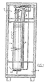
- FIG. 1 shows the cooling unit 1 in which a container 2 for a coolant 3 is connected to a number of pipes.
- the container 2 is filled with a coolant by way of a filling tube 4. Since the wall 5 of the container 2 is largely insulated by a vacuum sheath 6, the base 7 of the container 2 functions as a heat exchanger. This base 7 of the container 2 is not insulated, so that evaporation of the coolant is caused by way of the difference in temperature, so that pressure is built up. This overpressure is caused by the evaporation of the liquid nitrogen 8.
- the venturi 13 is protected against freezing by the moisture trap 10.
- the ambient air which is drawn in is collected in the moisture trap and the moisture in the ambient air is frozen solid by the evaporated coolant.
- the moisture trap may be regarded as a heat exchanger, by means of which moisture in the ambient air is temporarily frozen solid so that the operation of the venturi is not impaired.
- the most important function of the evaporated coolant 3 is to cool the storage space 9 by ensuring the air flow which is drawn in, together with the nitrogen gas 8 which is accelerated by the venturi 13, is forced into the storage space.
- the nitrogen gas 8 is compelled to exchange heat by way of a heat exchanger 14: cooling the storage space on the one hand and heating the nitrogen gas on the other hand.
- Another heat exchanger 15 is connected to the container at the base and provides additional cooling, e.g., if this is necessary in warmer periods.
- the design according to the embodiment of the invention has the same cooling power because of an adaptation of the pressure-regulating elements, irrespective of the level of the coolant in the container 2.
- venturi 13 causes the ambient air to be drawn in, circulation is caused as long as evaporation takes place, so that the temperature in the storage space is homogeneous.
- Figure 2 shows a lateral cross-section view of the preferred design of the cooling unit shown in Figure 1.
- the uppermost 14 and the lowest 15 heat exchangers can be clearly seen; the latter is an additional heat exchanger.
- the uppermost one reaches to the ceiling of the storage space 9. Cooling is obtained in the heat exchangers by the transfer of heat by way of the evaporated nitrogen.
- the level in the container 2 can be determined by a probe.
- Figure 3 contains a flow diagram of the preferred design of Figures 1 and 2.
- the liquid nitrogen 3 in the container 2 evaporates and provides cooling of the storage space by way of the first heat exchanger 7.
- the ambient air is drawn in through a venturi 13, so that circulation is created in the storage space, with the ambient air mixing with the evaporated coolant which has passed through the moisture trap. This mixture is returned to the environment.
- a third heat exchanger 20 is fitted to the base of the container 2.
- Figure 4 contains a flow diagram comparable to that of Figure 3.
- a different pressure-regulating system is used in this design, in which pressure-regulating elements 21 and a cut-off valve 22 are switched in series or in parallel.
- a further flow of liquid nitrogen is introduced into the storage space by other pressure-regulating elements 24 and temperature measurements 23 by way of pipe 25. Thermally controlled cooling of the storage space is caused in this way. The additional flow may cause additional mixing with the output flow - ambient air - of the evaporated nitrogen.
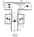
- FIG. 5 contains a diagram of the moisture trap and the venturi according to the invention.
- the moisture trap 27 consists of a pipe 30 for the ambient air; the low temperature T V dominates the moisture trap 27 is caused by the presence in direct or counter-flow of evaporated coolant, through which the moisture in the ambient air is frozen solid to the wall of the pipe 30. In this way ice 29 is formed on this wall 30.
- the flow of evaporated coolant is then led to the input of the venturi 28 by way of heat exchangers.
- the temperature T W is the temperature of the coolant after exchanging heat with the storage space and for preference is higher than the temperature T L of the ambient air from the moisture trap in order to exclude all phenomena of freezing from the venturi.
- Ambient air is drawn in through the constriction and mixing with the evaporated coolant and the ambient air which has been drawn in takes place; this is released into the storage space at point 31.
- a cooling unit according to the invention is used for preference in a storage space, e.g., a container or the body of a lorry used for the transport and distribution of foods.
- a calculation using the logistical data, such as transport time and ambient temperature and the volume of the storage space will enable the coolant level in the container to be adjusted. This level can be read off by means of a probe determining the level, for example. In this way regular cooling over time and in the storage space which satisfies all European standards for the transport of cooled and frozen foods.
Abstract
Description
- The invention relates to a cooling unit for cooling a storage space.
- Such cooling units are familiar and are used in particular for cooling frozen foods during transport and distribution. The familiar cooling units contain a container for a coolant, e.g. liquid nitrogen or carbon dioxide in the solid or fluid state. Heat is exchanged because of the evaporation of the coolant and the storage space is cooled.
- For example, in the US 4 576 010 a cryogenic control system for cooling a storage space within a road truck is described, where liquid nitrogen, stored in a tank, is evaporated by heat exchange with the air inside the storage space. The evaporated gas is conducted to a venturi where, due to the increase of pressure during evaporation, ambient air is sucked in, thus creating an air circulation in the storage space. In this way, the storage space will be cooled with high efficiency. However, due to the the direct contact with cold evaporated coolant, moisture contained in the ambient air sucked into the venturi will freeze out and finally block the venturi.
- In the US 3 447 336 a cooling unit is described where a cryogenic coolant - like liquid nitrogen - is fed to a venturi in its liquid state. To avoid the problem of freezing out of moisture inside the venturi, the ambient air sucked in is cooled down inside a moisture trap before it is fed to the venturi, leading to the effect that a mayor part of the moisture freezes out before it reaches the venturi. However, a minor part of the moisture still reaches the venturi and freezes out there. A cooling unit according to the preamble of claim 1 is disclosed in document US 3 447 336.
- New EU-directives on the storage and transport of frozen foods prescribe a temperature of -18°C during the entire process of storage and transport. The familiar cooling units are unable to ensure such a stable cooling temperature.
- The invention envisages overcoming these objections and to this, provides a cooling unit for cooling a storage space comprising a container for a cryogenic coolant, a first heat exchanger fluidly connected with said container for cooling said storage space by evaporating said cryogenic coolant, a moisture trap having an inlet and an outlet for cryogenic coolant and an inlet and an outlet for ambient air, for freezing moisture out of an airflow of air of said storage space by the means of thermal contact with said cryogenic fluidic, a venturi connected to said outlet for cryogenic coolant and to said outlet for ambient air of said moisture trap, for creating an air circulation in said storage space using the increase in pressure caused by said evaporation of the cryogenic coolant fluidly, by that a second heat exchanger for heating cryogenic coolant is located between the freezing element and the venturi.
- Hence, the cooling fulfils three functions:
- the cooling of the storage space through heat exchange with the evaporated or liquid coolant,
- freezing the moisture from the air that is drawn in by an element with a matching volume, termed the moisture trap, and
- circulating the ambient air by the suction caused by the acceleration of the evaporated coolant by the way of the venturi.
- Furthermore, temperature measurements make it possible to cause an additional direct influx of evaporated coolant by way of pressure-regulating elements and pipes. This provides thermally controlled cooling. In this way the cooling unit provides thermally controlled cooling and the temperature in the storage space will remain constant independent of the external ambient temperature. Moreover, the influx of this additional flow of evaporated coolant will cause a better mix with the cooled ambient air which is drawn in and returns to the storage space.
- The invention also relates to a storage space fitted with a mobile or stationary cooling unit according to the invention. Such a storage unit is suitable for the transport of frozen food.
- Finally, the invention also relates to a process for cooling a storage space according to claim 7.
- An embodiment of the invention will be described in greater detail on the basis of the following descriptions of the figures illustrating a number of preferred specimen designs of the cooling unit according to the invention.
- Figure 1 shows a front view in cross-section of a preferred design of a cooling unit in accordance with the present invention;
- Figure 2 shows the same preferred design as in Figure 1 in a side view;
- Figure 3 contains a flow diagram of the ambient air and the evaporated coolant in a cooling unit according to the invention;
- Figure 4 contains a flow diagram similar to that of Figure 3, in which an additional flow of evaporated coolant causes thermostatic operation.
- Figure 5 contains a diagrammatic cross-section, in which the operation of the moisture trap and the venturi is shown in a T-piece connector.
-
- Figure 1 shows the cooling unit 1 in which a
container 2 for acoolant 3 is connected to a number of pipes. Thecontainer 2 is filled with a coolant by way of afilling tube 4. Since the wall 5 of thecontainer 2 is largely insulated by a vacuum sheath 6, the base 7 of thecontainer 2 functions as a heat exchanger. This base 7 of thecontainer 2 is not insulated, so that evaporation of the coolant is caused by way of the difference in temperature, so that pressure is built up. This overpressure is caused by the evaporation of the liquid nitrogen 8. Since thecontainer 2 has not been closed off to the liquid nitrogen 8, nitrogen in the gaseous phase flows from thecontainer 2 because of the overpressure into an element with amatching volume 10, hereinafter to be termed a moisture trap, after which this gas flows through a heat exchanger and a venturi connection. This results in acceleration of the flow, so that underpressure is caused in the T-piece connection, which causes the ambient air to be drawn in through thepipe 26. - The
venturi 13 is protected against freezing by themoisture trap 10. The ambient air which is drawn in is collected in the moisture trap and the moisture in the ambient air is frozen solid by the evaporated coolant. The moisture trap may be regarded as a heat exchanger, by means of which moisture in the ambient air is temporarily frozen solid so that the operation of the venturi is not impaired. - The most important function of the evaporated coolant 3 (here nitrogen gas 8) is to cool the
storage space 9 by ensuring the air flow which is drawn in, together with the nitrogen gas 8 which is accelerated by theventuri 13, is forced into the storage space. - After the heat exchange in the
moisture trap 10, the nitrogen gas 8 is compelled to exchange heat by way of a heat exchanger 14: cooling the storage space on the one hand and heating the nitrogen gas on the other hand. - Another
heat exchanger 15 is connected to the container at the base and provides additional cooling, e.g., if this is necessary in warmer periods. - The design according to the embodiment of the invention has the same cooling power because of an adaptation of the pressure-regulating elements, irrespective of the level of the coolant in the
container 2. - Because the
venturi 13 causes the ambient air to be drawn in, circulation is caused as long as evaporation takes place, so that the temperature in the storage space is homogeneous. - Figure 2 shows a lateral cross-section view of the preferred design of the cooling unit shown in Figure 1. The uppermost 14 and the lowest 15 heat exchangers can be clearly seen; the latter is an additional heat exchanger. The uppermost one reaches to the ceiling of the
storage space 9. Cooling is obtained in the heat exchangers by the transfer of heat by way of the evaporated nitrogen. The level in thecontainer 2 can be determined by a probe. - Figure 3 contains a flow diagram of the preferred design of Figures 1 and 2. There are two types of flows: that of the evaporated coolant 16 (completely black triangle) and that of the ambient air 17 (triangle with O). The
liquid nitrogen 3 in thecontainer 2 evaporates and provides cooling of the storage space by way of the first heat exchanger 7. The ambient air is drawn in through aventuri 13, so that circulation is created in the storage space, with the ambient air mixing with the evaporated coolant which has passed through the moisture trap. This mixture is returned to the environment. Athird heat exchanger 20 is fitted to the base of thecontainer 2. - Figure 4 contains a flow diagram comparable to that of Figure 3. A different pressure-regulating system is used in this design, in which pressure-regulating
elements 21 and a cut-offvalve 22 are switched in series or in parallel. A further flow of liquid nitrogen is introduced into the storage space by other pressure-regulating elements 24 and temperature measurements 23 by way ofpipe 25. Thermally controlled cooling of the storage space is caused in this way. The additional flow may cause additional mixing with the output flow - ambient air - of the evaporated nitrogen. - Figure 5 contains a diagram of the moisture trap and the venturi according to the invention. The
moisture trap 27 consists of apipe 30 for the ambient air; the low temperature TV dominates themoisture trap 27 is caused by the presence in direct or counter-flow of evaporated coolant, through which the moisture in the ambient air is frozen solid to the wall of thepipe 30. In thisway ice 29 is formed on thiswall 30. The flow of evaporated coolant is then led to the input of theventuri 28 by way of heat exchangers. The temperature TW is the temperature of the coolant after exchanging heat with the storage space and for preference is higher than the temperature TL of the ambient air from the moisture trap in order to exclude all phenomena of freezing from the venturi. Ambient air is drawn in through the constriction and mixing with the evaporated coolant and the ambient air which has been drawn in takes place; this is released into the storage space atpoint 31. - A cooling unit according to the invention is used for preference in a storage space, e.g., a container or the body of a lorry used for the transport and distribution of foods. A calculation using the logistical data, such as transport time and ambient temperature and the volume of the storage space will enable the coolant level in the container to be adjusted. This level can be read off by means of a probe determining the level, for example. In this way regular cooling over time and in the storage space which satisfies all European standards for the transport of cooled and frozen foods.
Claims (9)
- Cooling unit for cooling a storage space (9) filled with ambient air comprising:characterised in that the first heat exchanger is formed by the base of the container and in that a second heat exchanger (14,19) for exchanging heat between the evaporated cryogenic coolant and the storage space (9) is located between the moisture trap (10,18,27) and the venturi (13,28).a container (2)for a cryogenic coolant,a first heat exchanger (7) for cooling said storage space (9) by evaporating said cryogenic coolant,a moisture trap (10,18,27) for freezing moisture of the ambient airthe moisture trap havinga first inlet and a first outlet for cryogenic coolant, the first inlet being connected to the container (2) anda second inlet and a second outlet for the ambient air,a venturi (13,28) for creating an air circulation in said storage space (9) using the increase in pressure caused by said evaporation of the cryogenic coolantthe venturi (13,28) havinga third inlet for the ambient air connected to the second outlet of the moisture trap (10,18,27),fourth inlet for the evaporated cryogenic coolant in communication with the first outlet of the moisture trap anda third outlet for the mixture of the ambient air and the evaporated cryogenic fluid,
- Cooling unit according to claim 1, characterised in that said inlet for cryogenic coolant of said moisture trap is fluidly connected with the first heat exchanger so that evaporated coolant is conducted through the moisture trap.
- Cooling unit according to claim 1 or 2, characterised in that pressure regulation means (21) are provided for controlling the evaporation of cryogenic coolant.
- Cooling unit according to one of the previous claims, characterised in that temperature sensors are provided.
- Cooling unit according to one of the previous claims, characterised in that the cooling unit is provided with means for moving the cooling unit from one storage space to another.
- Storage space fitted with a cooling unit according to one of the previous claims.
- Process for cooling a storage space (9) comprising the steps:- a cryogenic coolant stored in a container (2) is evaporated in a first heat exchanger (7) formed by the base of the container so that the storage space (9) is cooled,- the evaporated cryogenic coolant flows from the container (2) because of the overpressure intoa moisture trap (10,18,27), after which the evaporated cryogenic coolant flows througha second heat exchanger (14,19) for exchanging heat between the evaporated cryogenic coolant and the storage space (9) anda venturi (13,28),- the evaporated cryogenic coolant is accelerated in the venturi (13,28), so that an underpressure is caused in the venturi (28,13), which causes the ambient air of the storage space (9) to be drawn in,- the ambient air which is drawn into the venturi (28,13) together with the evaporated cryogenic coolant which is accelerated by the venturi (28,13) is forced into the storage space (9), so that the ambient air in the storage space (9) is caused to circulate,- the ambient air before being drawn into the venturi (13) passes the moisture trap (10,18,27), so that the moisture in the ambient air is frozen solid by the evaporated cryogenic coolant.
- Process according to claim 7, characterised in that liquid nitrogen and/or solid or liquid carbon dioxide is used as cryogenic coolant.
- Process according to one of the claims 7 or 8, characterised in that thermally controlled cooling is created by regulation of pressure and/or regulation of temperature.
Applications Claiming Priority (2)
| Application Number | Priority Date | Filing Date | Title |
|---|---|---|---|
| NL1003915 | 1996-08-29 | ||
| NL1003915A NL1003915C2 (en) | 1996-08-29 | 1996-08-29 | Cooling device. |
Publications (2)
| Publication Number | Publication Date |
|---|---|
| EP0826937A1 EP0826937A1 (en) | 1998-03-04 |
| EP0826937B1 true EP0826937B1 (en) | 2003-07-16 |
Family
ID=19763434
Family Applications (1)
| Application Number | Title | Priority Date | Filing Date |
|---|---|---|---|
| EP97114434A Expired - Lifetime EP0826937B1 (en) | 1996-08-29 | 1997-08-21 | Cooling unit |
Country Status (5)
| Country | Link |
|---|---|
| EP (1) | EP0826937B1 (en) |
| AT (1) | ATE245270T1 (en) |
| DE (1) | DE69723515D1 (en) |
| NL (1) | NL1003915C2 (en) |
| ZA (1) | ZA977372B (en) |
Cited By (2)
| Publication number | Priority date | Publication date | Assignee | Title |
|---|---|---|---|---|
| EP1593918A2 (en) | 2004-05-06 | 2005-11-09 | Air Liquide Deutschland GmbH | Indirect cooling of refrigerated vehicles |
| EP1659355A2 (en) | 2004-11-17 | 2006-05-24 | Air Liquide Deutschland GmbH | Cooling process and cooling apparatus for refrigerated vehicles |
Families Citing this family (3)
| Publication number | Priority date | Publication date | Assignee | Title |
|---|---|---|---|---|
| DE102006016555A1 (en) * | 2006-04-07 | 2007-10-11 | Air Liquide Deutschland Gmbh | Method and device for establishing an overpressure in a liquefied gas tank of a refrigerated vehicle and cooling system for a refrigerated vehicle and refrigerated vehicle |
| DE102006016559A1 (en) * | 2006-04-07 | 2007-10-11 | Air Liquide Deutschland Gmbh | Heat exchanger for a mobile refrigerated vehicle |
| DE102006016557A1 (en) * | 2006-04-07 | 2007-10-11 | Air Liquide Deutschland Gmbh | Refrigerated vehicle with external cooling module and cooling method |
Family Cites Families (7)
| Publication number | Priority date | Publication date | Assignee | Title |
|---|---|---|---|---|
| US3271970A (en) * | 1962-10-29 | 1966-09-13 | Pennsylvania Wmb Inc | Insulated cold storage rooms or similar enclosures |
| US3163022A (en) * | 1963-01-21 | 1964-12-29 | Z Z Corp | Refrigeration system employing expendable refrigerant |
| US3447336A (en) * | 1967-09-22 | 1969-06-03 | Pullman Inc | Refrigeration arrangement |
| US3447334A (en) * | 1967-12-07 | 1969-06-03 | Garrett Corp | Environmental system for preservation of perishables |
| GB1594576A (en) * | 1976-11-16 | 1981-07-30 | Boc Ltd | Refrigeration apparatus |
| US4576010A (en) * | 1983-10-18 | 1986-03-18 | Nhy-Temp, Inc. | Cryogenic refrigeration control system |
| CA2095494C (en) * | 1992-06-10 | 1998-08-11 | Ron C. Lee | Cooling method and apparatus |
-
1996
- 1996-08-29 NL NL1003915A patent/NL1003915C2/en not_active IP Right Cessation
-
1997
- 1997-08-15 ZA ZA9707372A patent/ZA977372B/en unknown
- 1997-08-21 DE DE69723515T patent/DE69723515D1/en not_active Expired - Lifetime
- 1997-08-21 AT AT97114434T patent/ATE245270T1/en not_active IP Right Cessation
- 1997-08-21 EP EP97114434A patent/EP0826937B1/en not_active Expired - Lifetime
Cited By (2)
| Publication number | Priority date | Publication date | Assignee | Title |
|---|---|---|---|---|
| EP1593918A2 (en) | 2004-05-06 | 2005-11-09 | Air Liquide Deutschland GmbH | Indirect cooling of refrigerated vehicles |
| EP1659355A2 (en) | 2004-11-17 | 2006-05-24 | Air Liquide Deutschland GmbH | Cooling process and cooling apparatus for refrigerated vehicles |
Also Published As
| Publication number | Publication date |
|---|---|
| DE69723515D1 (en) | 2003-08-21 |
| ATE245270T1 (en) | 2003-08-15 |
| EP0826937A1 (en) | 1998-03-04 |
| ZA977372B (en) | 1998-02-19 |
| NL1003915C2 (en) | 1998-03-04 |
Similar Documents
| Publication | Publication Date | Title |
|---|---|---|
| US3385073A (en) | Refrigeration system for shipping perishable commodities | |
| JP3029869B2 (en) | CO 2 Lower 2 Enthalpy control for refrigerator | |
| US5564277A (en) | Dehumidifier for cryogenic refrigeration system | |
| US8763409B2 (en) | LNG (liquefied natural gas) and LIN (liquid nitrogen) in transit refrigeration heat exchange system | |
| US20150192249A1 (en) | Equipment and method for filling pressurized gas cylinders from a liquefied gas tank | |
| EP1236960B1 (en) | Preservation apparatus particularly for perishable products at a preset temperature | |
| JP2003220823A (en) | Low-temperature controller and controlling method thereof | |
| WO1994024498A1 (en) | Self-contained cooler/freezer apparatus | |
| US20080148755A1 (en) | Cooling apparatus for on-vehicle electronic device | |
| US20200378676A1 (en) | Passive refrigeration system for the cold chain industry | |
| CN106568264A (en) | Fast cooling box with cold accumulation function | |
| EP2543947A1 (en) | Cryogen heat pipe heat exchanger | |
| US20240027123A1 (en) | Method and System for Cooler Conversion to a Refrigerator | |
| EP0826937B1 (en) | Cooling unit | |
| US2125888A (en) | Dry ice refrigerating apparatus | |
| US7089997B2 (en) | Heat exchanger using water liquid and vapor phases transformation to enhance heat exchange performance | |
| CN1097505A (en) | Self-contained cooler/freezer apparatus | |
| WO2002016836A1 (en) | Stirling cooling device, cooling chamber, and refrigerator | |
| CN110345662A (en) | A kind of agent bin refrigeration structure and agent bin for eliminating condensed water | |
| CN112334717A (en) | Multi-temperature transport refrigeration system and method | |
| JP2002372397A (en) | Cooling system | |
| US11719449B2 (en) | Systems for refrigerating an enclosure | |
| US11813925B2 (en) | Methods and systems for maintaining cargo at an ultra-low temperature over an extended period of time | |
| BR102019009105A2 (en) | isothermal tank vehicle with autonomous refrigeration means | |
| EP3792087B1 (en) | Cooling installation and method for cooling a storage chamber of a transport vehicle |
Legal Events
| Date | Code | Title | Description |
|---|---|---|---|
| PUAI | Public reference made under article 153(3) epc to a published international application that has entered the european phase |
Free format text: ORIGINAL CODE: 0009012 |
|
| AK | Designated contracting states |
Kind code of ref document: A1 Designated state(s): AT BE CH DE ES FI FR GB GR IT LI NL SE |
|
| 17P | Request for examination filed |
Effective date: 19980904 |
|
| AKX | Designation fees paid |
Free format text: AT BE CH DE ES FI FR GB GR IT LI NL SE |
|
| AXX | Extension fees paid |
Free format text: SI PAYMENT 980904 |
|
| RBV | Designated contracting states (corrected) |
Designated state(s): AT BE CH DE ES FI FR GB GR IT LI NL SE |
|
| 17Q | First examination report despatched |
Effective date: 20010220 |
|
| RAP1 | Party data changed (applicant data changed or rights of an application transferred) |
Owner name: MESSER GRIESHEIM GMBH |
|
| GRAH | Despatch of communication of intention to grant a patent |
Free format text: ORIGINAL CODE: EPIDOS IGRA |
|
| GRAH | Despatch of communication of intention to grant a patent |
Free format text: ORIGINAL CODE: EPIDOS IGRA |
|
| GRAA | (expected) grant |
Free format text: ORIGINAL CODE: 0009210 |
|
| AK | Designated contracting states |
Designated state(s): AT BE CH DE ES FI FR GB GR IT LI NL SE |
|
| AX | Request for extension of the european patent |
Extension state: SI |
|
| PG25 | Lapsed in a contracting state [announced via postgrant information from national office to epo] |
Ref country code: LI Free format text: LAPSE BECAUSE OF FAILURE TO SUBMIT A TRANSLATION OF THE DESCRIPTION OR TO PAY THE FEE WITHIN THE PRESCRIBED TIME-LIMIT Effective date: 20030716 Ref country code: IT Free format text: LAPSE BECAUSE OF FAILURE TO SUBMIT A TRANSLATION OF THE DESCRIPTION OR TO PAY THE FEE WITHIN THE PRESCRIBED TIME-LIMIT;WARNING: LAPSES OF ITALIAN PATENTS WITH EFFECTIVE DATE BEFORE 2007 MAY HAVE OCCURRED AT ANY TIME BEFORE 2007. THE CORRECT EFFECTIVE DATE MAY BE DIFFERENT FROM THE ONE RECORDED. Effective date: 20030716 Ref country code: FR Free format text: LAPSE BECAUSE OF FAILURE TO SUBMIT A TRANSLATION OF THE DESCRIPTION OR TO PAY THE FEE WITHIN THE PRESCRIBED TIME-LIMIT Effective date: 20030716 Ref country code: FI Free format text: LAPSE BECAUSE OF FAILURE TO SUBMIT A TRANSLATION OF THE DESCRIPTION OR TO PAY THE FEE WITHIN THE PRESCRIBED TIME-LIMIT Effective date: 20030716 Ref country code: CH Free format text: LAPSE BECAUSE OF FAILURE TO SUBMIT A TRANSLATION OF THE DESCRIPTION OR TO PAY THE FEE WITHIN THE PRESCRIBED TIME-LIMIT Effective date: 20030716 Ref country code: BE Free format text: LAPSE BECAUSE OF FAILURE TO SUBMIT A TRANSLATION OF THE DESCRIPTION OR TO PAY THE FEE WITHIN THE PRESCRIBED TIME-LIMIT Effective date: 20030716 Ref country code: AT Free format text: LAPSE BECAUSE OF FAILURE TO SUBMIT A TRANSLATION OF THE DESCRIPTION OR TO PAY THE FEE WITHIN THE PRESCRIBED TIME-LIMIT Effective date: 20030716 |
|
| REG | Reference to a national code |
Ref country code: GB Ref legal event code: FG4D |
|
| PGFP | Annual fee paid to national office [announced via postgrant information from national office to epo] |
Ref country code: DE Payment date: 20030725 Year of fee payment: 7 |
|
| REG | Reference to a national code |
Ref country code: CH Ref legal event code: EP |
|
| REF | Corresponds to: |
Ref document number: 69723515 Country of ref document: DE Date of ref document: 20030821 Kind code of ref document: P |
|
| PG25 | Lapsed in a contracting state [announced via postgrant information from national office to epo] |
Ref country code: SE Free format text: LAPSE BECAUSE OF FAILURE TO SUBMIT A TRANSLATION OF THE DESCRIPTION OR TO PAY THE FEE WITHIN THE PRESCRIBED TIME-LIMIT Effective date: 20031016 Ref country code: GR Free format text: LAPSE BECAUSE OF FAILURE TO SUBMIT A TRANSLATION OF THE DESCRIPTION OR TO PAY THE FEE WITHIN THE PRESCRIBED TIME-LIMIT Effective date: 20031016 Ref country code: GB Free format text: LAPSE BECAUSE OF NON-PAYMENT OF DUE FEES Effective date: 20031016 |
|
| PG25 | Lapsed in a contracting state [announced via postgrant information from national office to epo] |
Ref country code: DE Free format text: LAPSE BECAUSE OF FAILURE TO SUBMIT A TRANSLATION OF THE DESCRIPTION OR TO PAY THE FEE WITHIN THE PRESCRIBED TIME-LIMIT Effective date: 20031017 |
|
| PG25 | Lapsed in a contracting state [announced via postgrant information from national office to epo] |
Ref country code: ES Free format text: LAPSE BECAUSE OF FAILURE TO SUBMIT A TRANSLATION OF THE DESCRIPTION OR TO PAY THE FEE WITHIN THE PRESCRIBED TIME-LIMIT Effective date: 20031027 |
|
| REG | Reference to a national code |
Ref country code: CH Ref legal event code: PL |
|
| PLBE | No opposition filed within time limit |
Free format text: ORIGINAL CODE: 0009261 |
|
| STAA | Information on the status of an ep patent application or granted ep patent |
Free format text: STATUS: NO OPPOSITION FILED WITHIN TIME LIMIT |
|
| GBPC | Gb: european patent ceased through non-payment of renewal fee |
Effective date: 20031016 |
|
| 26N | No opposition filed |
Effective date: 20040419 |
|
| EN | Fr: translation not filed | ||
| PGFP | Annual fee paid to national office [announced via postgrant information from national office to epo] |
Ref country code: NL Payment date: 20040803 Year of fee payment: 8 |
|
| PG25 | Lapsed in a contracting state [announced via postgrant information from national office to epo] |
Ref country code: NL Free format text: LAPSE BECAUSE OF NON-PAYMENT OF DUE FEES Effective date: 20060301 |
|
| NLV4 | Nl: lapsed or anulled due to non-payment of the annual fee |
Effective date: 20060301 |