EP1327599A1 - Elevator device - Google Patents
Elevator device Download PDFInfo
- Publication number
- EP1327599A1 EP1327599A1 EP00950050A EP00950050A EP1327599A1 EP 1327599 A1 EP1327599 A1 EP 1327599A1 EP 00950050 A EP00950050 A EP 00950050A EP 00950050 A EP00950050 A EP 00950050A EP 1327599 A1 EP1327599 A1 EP 1327599A1
- Authority
- EP
- European Patent Office
- Prior art keywords
- main rope
- hoistway
- driving
- sheave
- covering member
- Prior art date
- Legal status (The legal status is an assumption and is not a legal conclusion. Google has not performed a legal analysis and makes no representation as to the accuracy of the status listed.)
- Granted
Links
Images



Classifications
-
- B—PERFORMING OPERATIONS; TRANSPORTING
- B66—HOISTING; LIFTING; HAULING
- B66B—ELEVATORS; ESCALATORS OR MOVING WALKWAYS
- B66B7/00—Other common features of elevators
- B66B7/02—Guideways; Guides
- B66B7/04—Riding means, e.g. Shoes, Rollers, between car and guiding means, e.g. rails, ropes
- B66B7/047—Shoes, sliders
-
- B—PERFORMING OPERATIONS; TRANSPORTING
- B66—HOISTING; LIFTING; HAULING
- B66B—ELEVATORS; ESCALATORS OR MOVING WALKWAYS
- B66B11/00—Main component parts of lifts in, or associated with, buildings or other structures
- B66B11/0065—Roping
- B66B11/008—Roping with hoisting rope or cable operated by frictional engagement with a winding drum or sheave
-
- B—PERFORMING OPERATIONS; TRANSPORTING
- B66—HOISTING; LIFTING; HAULING
- B66B—ELEVATORS; ESCALATORS OR MOVING WALKWAYS
- B66B11/00—Main component parts of lifts in, or associated with, buildings or other structures
- B66B11/04—Driving gear ; Details thereof, e.g. seals
- B66B11/08—Driving gear ; Details thereof, e.g. seals with hoisting rope or cable operated by frictional engagement with a winding drum or sheave
-
- B—PERFORMING OPERATIONS; TRANSPORTING
- B66—HOISTING; LIFTING; HAULING
- B66B—ELEVATORS; ESCALATORS OR MOVING WALKWAYS
- B66B7/00—Other common features of elevators
- B66B7/06—Arrangements of ropes or cables
-
- D—TEXTILES; PAPER
- D07—ROPES; CABLES OTHER THAN ELECTRIC
- D07B—ROPES OR CABLES IN GENERAL
- D07B1/00—Constructional features of ropes or cables
- D07B1/14—Ropes or cables with incorporated auxiliary elements, e.g. for marking, extending throughout the length of the rope or cable
- D07B1/145—Ropes or cables with incorporated auxiliary elements, e.g. for marking, extending throughout the length of the rope or cable comprising elements for indicating or detecting the rope or cable status
-
- D—TEXTILES; PAPER
- D07—ROPES; CABLES OTHER THAN ELECTRIC
- D07B—ROPES OR CABLES IN GENERAL
- D07B1/00—Constructional features of ropes or cables
- D07B1/16—Ropes or cables with an enveloping sheathing or inlays of rubber or plastics
- D07B1/162—Ropes or cables with an enveloping sheathing or inlays of rubber or plastics characterised by a plastic or rubber enveloping sheathing
Definitions
- the present invention relates to an elevator apparatus using a main rope a surface of which is covered with a covering member made of a material with a high frictional coefficient.
- Japanese Patent Application Laid-Open No. Hei 7-267534 shows a main rope for an elevator which is composed of a synthetic fiber rope.
- the synthetic fiber rope has a rope body and a covering member covering an outer periphery of the rope body.
- the rope body is constructed by twisting a plurality of strands each of which is composed of aramid fibers and an impregnating agent such as polyurethane.
- the covering member is made of, for example, polyurethane.
- the present invention is made to solve the problems mentioned above, and an object of the present invention is to provide an elevator apparatus in which the transmission efficiency of driving force between a driving sheave and a main rope can be further improved.
- an elevator apparatus comprising: a hoistway; a driving machine having a driving sheave; a main rope wound around the driving sheave and having a main rope body and a covering member made of resin, the covering member covering an outer periphery of the main rope body; and a car suspended in the hoistway by the main rope and raised and lowered by the driving machine; wherein the driving sheave has a sheave body and a rope receiving member made of a material with a higher frictional coefficient than the sheave body, the sheave body having a groove in which the main rope is inserted formed at an outer peripheral surface thereof, and the rope receiving member is provided along an inner surface of the groove.
- an elevator apparatus comprising: a hoistway; a guide rail provided in the hoistway; a driving machine having a driving sheave; a main rope wound around the driving sheave and having a main rope body and a covering member made of resin, the covering member covering an outer periphery of the main rope body; and a car suspended in the hoistway by the main rope and raised and lowered along the guide rail by the driving machine; wherein a non-lubricated type guiding device engaging with the guide rail is attached to the car.
- an elevator apparatus comprising: a hoistway; a driving machine having a driving sheave; a main rope wound around the driving sheave and having a main rope body and a covering member made of resin, the covering member covering an outer periphery of the main rope body; a car suspended in the hoistway by the main rope and raised and lowered by the driving machine; and an oil buffer for buffering an impact of the car, provided at a bottom portion of the hoistway; wherein the oil buffer is surrounded by a flexible cover for preventing dispersion of oil in the oil buffer to the surrounding area.
- an elevator apparatus comprising: a hoistway; a guide rail provided in the hoistway; a rail bracket for fixing the guide rail to the hoistway; a driving machine having a driving sheave; a main rope wound around the driving sheave and having a main rope body and a covering member made of resin, the covering member covering an outer periphery of the main rope body; and a car suspended in the hoistway by the main rope and raised and lowered along the guide rail by the driving machine; wherein the rail bracket is fixed in the hoistway by a non-welding process using a fastening device.
- an elevator apparatus comprising: a hoistway; a driving machine having a driving sheave; a main rope wound around the driving sheave, a surface of the main rope being covered by a covering member made of resin; and a car suspended in the hoistway by the main rope and raised and lowered by the driving machine; wherein a surface portion of the driving sheave contacting the main rope is composed of conductive material; a conductive member is provided inside of the covering member; and a detecting apparatus is connected to the surface portion and the conductive member, for detecting damage to the covering member when the surface portion becomes electrically conductive with the conductive member.
- an elevator apparatus comprising: a hoistway; a driving machine having a driving sheave; a main rope wound around the driving sheave and having a main rope body and a covering member made of resin, the covering member covering an outer periphery of the main rope body; and a car suspended in the hoistway by the main rope and raised and lowered by the driving machine; the elevator apparatus further comprising a brake device for braking the car by directly gripping the main rope.
- Fig. 1 is a side view showing an elevator apparatus according to a first embodiment of the present invention
- Fig. 2 is a cross-sectional view taken along the line II-II in Fig. 1.
- a pair of car guide rails 2 and a pair of counterweight guide rails 3 are installed in a hoistway 1.
- the guide rails 2 and 3 are fixed through a plurality of rail brackets 5 to building side fittings 4 fixed to a building.
- the rail brackets 5 are fixed to the building side fittings 4 by a non-welding process using a plurality of bolts 6 as a fastening device.
- the guide rails 2 and 3 are fastened to the rail brackets 5 by a plurality of rail clips (not shown).
- a deflector sheave 7 and a driving machine (hoisting machine) 8 are disposed at an upper portion of the hoistway 1.
- the driving machine 8 has a driving machine body 9 and a driving sheave 10 rotated by the driving machine body 9.
- a plurality of main ropes 11 are wound around the driving sheave 10 and the deflector sheave 7.
- a car 12 is suspended at one end portion of the main ropes 11.
- a counterweight 13 is suspended at the other end portion of the main ropes 11.
- the car 12 is guided by the car guide rails 2 to be raised and lowered in the hoistway 1.
- the counterweight 13 is guided by the counterweight guide rails 3 to be raised and lowered in the hoistway 1.
- a plurality of car guide shoes 14 and a plurality of counterweight guide shoes 15 as non-lubricated type guiding devices which engage with the guide rails 2 and 3 are attached to the car 12 and the counterweight 13.
- the guide shoes 14 and 15 are sliding guide shoes which are predominantly composed of wax or polyethylene and do not need to be supplied oil.
- a car side buffer 16 buffering the shock of an impact by the car 12 and a counterweight side buffer 17 buffering the shock of an impact by the counterweight 13 are installed at a bottom portion (pit) 1a of the hoistway 1.
- These buffers 16 and 17 are oil buffers.
- the buffers 16 and 17 are surrounded by flexible covers 18 and 19 to prevent dispersion of oil in the oil buffers 16 and 17 to the surrounding area.
- Fig. 3 is a cross-sectional view of the main rope 11 in Fig. 1.
- the main rope 11 has a rope body 21 composed of high strength synthetic fibers, a plurality of conductive members 22 disposed into a spiral on the outer periphery of the rope body 21, and a covering member 23 covering the outer periphery of the rope body 21 and the conductive members 22.
- the rope body 21 is constructed by twisting a plurality of strands 24 composed of aramid fibers and an impregnating agent such as polyurethane or the like around each other.
- the conductive members 22 are composed of, for example, carbon fibers, iron or copper. More, the covering member 23 is composed of, for example, polyurethane, polyethylene or the like.
- Fig. 4 is a cross-sectional view of an essential portion of the driving sheave 10 in Fig. 1.
- the driving sheave 10 has a sheave body 25 made of metal at the outer peripheral surface of which grooves 25a are formed, rope receiving members 26 provided along the inner surfaces of the grooves 25a, and groove entrance members 27 provided at the edge portions of the opening portions of the grooves 25a.
- the main ropes 11 are inserted in the grooves 25a.
- the rope receiving members 26 are made of a material with a higher frictional coefficient than the sheave body 25.
- the groove entrance members 27 are made of a material with a lower frictional coefficient than the rope receiving members 26. Further, in this embodiment, the rope receiving members 26 are made of the same material as the covering member 23.
- the rope receiving members 26 having a high frictional coefficient are provided in the grooves 25a of the driving sheave 10, the transmission efficiency of the driving force between the driving sheave 10 and the main ropes 11 can be improved. Further, since the rope receiving members 26 are made of the same material as the covering member 23, the frictional force between the driving sheave 10 and the main ropes 11 can be improved effectively. Furthermore, since the groove entrance members 27 made of low frictional coefficient material are disposed at the edge portions of the opening portions of the grooves 25a, the friction when the main ropes 11 are inserted in and moved out from the grooves 25a is reduced, thereby preventing damage to the main ropes 11 and prolonging the life of the main ropes 11.
- roller guide shoes which need to be supplied oil are not used, and the non-lubricated and sliding type guide shoes 14 and 15 are used as the guiding devices, the surfaces of the main ropes 11 are prevented from being stained by oil, thereby maintaining the transmission efficiency of the driving force between the driving sheave 10 and the main ropes 11.
- the buffers 16 and 17 are surrounded by covers 18 and 19, so dispersion of oil in the buffers 16 and 17 to the surrounding area is prevented, to also prevent the surfaces of the main ropes 11 from being stained by oil, thereby maintaining the transmission efficiency of the driving force between the driving sheave 10 and the main ropes 11.
- the rail brackets 5 are fixed in the hoistway 1 by a non-welding process using the bolts 6, so the main ropes 11 are prevented from being damaged by sparks generated during welding, thereby maintaining the transmission efficiency of the driving force between the driving sheave 10 and the main ropes 11.
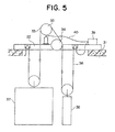
- Fig. 5 is a structural view showing an elevator apparatus according to a second embodiment of the present invention.
- a machine base 32 is installed at an upper portion of the hoistway 31.
- a driving machine 33 and a deflector sheave 34 are mounted to the machine base 32.
- the driving machine 33 has a driving sheave 35.
- a main rope 36 is wound around the driving sheave 35 and the deflector sheave 34.
- the cross sectional structure of the main rope 36 is the same as in Fig. 3, and the conductive members 22 are provided inside the covering member 23. Further, the surface portion of the driving sheave 35 contacting the main rope 36 is composed of conductive material.
- a car 37 and a counterweight 38 are suspended in the hoistway 1 by the main rope 36.
- a detecting apparatus 39 is installed on the machine base 32. The detecting apparatus 39 is electrically connected to the surface portion of the driving sheave 35 and the conductive members 22 through wires 40, so any damage to the covering member 23 is defected by electrical continuity between the surface portion of the driving sheave 35 and the conductive members 22.
- Fig. 6 is a structural view showing an elevator apparatus according to a third embodiment of the present invention.
- a driving machine 42 and a deflector sheave 43 are disposed at an upper portion of a hoistway 41.
- the driving machine 42 has a driving sheave 44.
- a main rope 45 is wound around the driving sheave 44 and the deflector sheave 43.
- the cross sectional structure of the main rope 45 is the same as in Fig. 3, and its surface is covered by the covering member 23 made of high frictional coefficient material.
- a car 46 is suspended at one end portion of the main rope 45.
- a counterweight 47 is suspended at the other end portion of the main rope 45.
- a brake device 48 for braking the car 46 by directly gripping the main rope 45 is disposed at the upper portion of the hoistway 41.
- lining material having a frictional coefficient of about 0.3 are used in brake devices of conventional elevators, since the covering member 23 made of polyurethane, polyethylene or the like has a frictional coefficient of about 0.4 to 0.6, a reduction in brake device size is possible by using the brake device 48 which directly grips the main rope 45.
Landscapes
- Engineering & Computer Science (AREA)
- Civil Engineering (AREA)
- Mechanical Engineering (AREA)
- Structural Engineering (AREA)
- Lift-Guide Devices, And Elevator Ropes And Cables (AREA)
Abstract
Description
Claims (9)
- An elevator apparatus comprising:wherein said driving sheave has a sheave body and a rope receiving member made of a material with a higher frictional coefficient than said sheave body, said sheave body having a groove in which said main rope is inserted formed at an outer peripheral surface thereof, and said rope receiving member is provided along an inner surface of said groove.a hoistway;a driving machine having a driving sheave;a main rope wound around said driving sheave and having a main rope body and a covering member made of resin, said covering member covering an outer periphery of said main rope body; anda car suspended in said hoistway by said main rope and raised and lowered by said driving machine;
- An elevator apparatus as defined in claim 1, wherein said rope receiving member is made of the same material as said covering member.
- An elevator apparatus as defined in claim 1, wherein a groove entrance member made of a material with a lower frictional coefficient than said rope receiving member is provided at an edge portion of an opening portion of said groove.
- An elevator apparatus comprising:wherein a non-lubricated type guiding device engaging with said guide rail is attached to said car.a hoistway;a guide rail provided in said hoistway;a driving machine having a driving sheave;a main rope wound around said driving sheave and having a main rope body and a covering member made of resin, said covering member covering an outer periphery of said main rope body; anda car suspended in said hoistway by said main rope and raised and lowered along said guide rail by said driving machine;
- An elevator apparatus comprising:wherein said oil buffer is surrounded by a flexible cover for preventing dispersion of oil in said oil buffer to the surrounding area.a hoistway;a driving machine having a driving sheave;a main rope wound around said driving sheave and having a main rope body and a covering member made of resin, said covering member covering an outer periphery of said main rope body;a car suspended in said hoistway by said main rope and raised and lowered by said driving machine; andan oil buffer for buffering an impact of said car, provided at a bottom portion of said hoistway;
- An elevator apparatus comprising:wherein said rail bracket is fixed in said hoistway by a non-welding process using a fastening device.a hoistway;a guide rail provided in said hoistway;a rail bracket for fixing said guide rail to said hoistway; a driving machine having a driving sheave;a main rope wound around said driving sheave and having a main rope body and a covering member made of resin, said covering member covering an outer periphery of said main rope body; anda car suspended in said hoistway by said main rope and raised and lowered along said guide rail by said driving machine;
- An elevator apparatus comprising:wherein a surface portion of said driving sheave contacting said main rope is composed of conductive material;a hoistway;a driving machine having a driving sheave;a main rope wound around said driving sheave, a surface of said main rope being covered by a covering member made of resin; anda car suspended in said hoistway by said main rope and raised and lowered by said driving machine;a conductive member is provided inside of said covering member; anda detecting apparatus is connected to said surface portion and said conductive member, for detecting damage to said covering member when said surface portion becomes electrically conductive with said conductive member.
- An elevator apparatus comprising:a hoistway;a driving machine having a driving sheave;a main rope wound around said driving sheave and having a main rope body and a covering member made of resin, said covering member covering an outer periphery of said main rope body; anda car suspended in said hoistway by said main rope and raised and lowered by said driving machine;said elevator apparatus further comprising a brake device for braking said car by directly gripping said main rope.
- An elevator apparatus as defined in any one of claims 1 to 8, wherein said main rope body is composed of high strength synthetic fibers.
Priority Applications (1)
| Application Number | Priority Date | Filing Date | Title |
|---|---|---|---|
| EP06015383A EP1710192A3 (en) | 2000-08-09 | 2000-08-09 | Elevator apparatus |
Applications Claiming Priority (1)
| Application Number | Priority Date | Filing Date | Title |
|---|---|---|---|
| PCT/JP2000/005335 WO2002012108A1 (en) | 2000-08-09 | 2000-08-09 | Elevator device |
Related Child Applications (1)
| Application Number | Title | Priority Date | Filing Date |
|---|---|---|---|
| EP06015383A Division EP1710192A3 (en) | 2000-08-09 | 2000-08-09 | Elevator apparatus |
Publications (3)
| Publication Number | Publication Date |
|---|---|
| EP1327599A1 true EP1327599A1 (en) | 2003-07-16 |
| EP1327599A4 EP1327599A4 (en) | 2004-06-30 |
| EP1327599B1 EP1327599B1 (en) | 2007-03-21 |
Family
ID=11736339
Family Applications (1)
| Application Number | Title | Priority Date | Filing Date |
|---|---|---|---|
| EP00950050A Expired - Lifetime EP1327599B1 (en) | 2000-08-09 | 2000-08-09 | Elevator device |
Country Status (6)
| Country | Link |
|---|---|
| EP (1) | EP1327599B1 (en) |
| JP (1) | JP4727123B2 (en) |
| KR (2) | KR100511850B1 (en) |
| CN (1) | CN1373733A (en) |
| DE (1) | DE60034072T2 (en) |
| WO (1) | WO2002012108A1 (en) |
Cited By (8)
| Publication number | Priority date | Publication date | Assignee | Title |
|---|---|---|---|---|
| WO2003101876A1 (en) | 2002-05-30 | 2003-12-11 | Mitsubishi Denki Kabushiki Kaisha | Elevator device |
| EP2020398A1 (en) * | 2007-08-03 | 2009-02-04 | ORONA S. Coop. | Rope for elevator apparatuses and elevator apparatus comprising said rope |
| EP2082983A1 (en) * | 2008-01-28 | 2009-07-29 | ThyssenKrupp Aufzugswerke GmbH | Lift assembly |
| CN101016136B (en) * | 2006-02-10 | 2011-03-09 | 株式会社日立制作所 | Elevator device |
| EP1586526A4 (en) * | 2003-01-24 | 2011-06-01 | Mitsubishi Electric Corp | LIFT CABLE |
| EP1726554A4 (en) * | 2004-03-01 | 2012-01-11 | Mitsubishi Electric Corp | RESIN CABLE AND ELEVATOR POSITION SENSOR USING THE SAME |
| EP1803676A4 (en) * | 2004-10-20 | 2012-03-14 | Mitsubishi Electric Corp | ELEVATOR EQUIPMENT |
| EP1657208B1 (en) | 2003-06-19 | 2013-12-25 | Inventio AG | Drive pulley with coating |
Families Citing this family (11)
| Publication number | Priority date | Publication date | Assignee | Title |
|---|---|---|---|---|
| EP1602613A1 (en) * | 2003-03-12 | 2005-12-07 | Mitsubishi Denki Kabushiki Kaisha | Counterbalancing self-running elevator |
| CN101143677B (en) * | 2004-04-14 | 2010-06-09 | 三菱电机株式会社 | Elevator device |
| WO2005100225A1 (en) * | 2004-04-14 | 2005-10-27 | Mitsubishi Denki Kabushiki Kaisha | Elevator apparatus |
| EP1795483A4 (en) * | 2004-09-30 | 2011-08-10 | Mitsubishi Electric Corp | ELEVATOR |
| CN1926052B (en) * | 2004-12-15 | 2012-06-06 | 三菱电机株式会社 | Traction machine for elevator |
| JP2010195580A (en) * | 2009-02-27 | 2010-09-09 | Toshiba Elevator Co Ltd | Suspension rope |
| JP5060567B2 (en) * | 2010-01-22 | 2012-10-31 | 株式会社日立製作所 | Elevator rope winding method and member |
| CN102491151A (en) * | 2011-12-16 | 2012-06-13 | 苏州市东沪电缆有限公司 | Pseudo trailing elevator cable assembly |
| WO2017198612A1 (en) * | 2016-05-17 | 2017-11-23 | Inventio Ag | Method and device for detecting damage in a support means for an elevator system |
| US11111108B2 (en) * | 2018-05-04 | 2021-09-07 | Otis Elevator Company | Coated sheave |
| CN111039125A (en) * | 2018-10-15 | 2020-04-21 | 潘实 | A hydraulic buffer device |
Family Cites Families (17)
| Publication number | Priority date | Publication date | Assignee | Title |
|---|---|---|---|---|
| JPS5844596B2 (en) * | 1976-03-10 | 1983-10-04 | 三菱電機株式会社 | Elevator emergency stop device |
| JPS55151479A (en) * | 1979-05-09 | 1980-11-26 | Hitachi Ltd | Elevator |
| JPS6055436B2 (en) * | 1981-04-09 | 1985-12-05 | 三菱電機株式会社 | Elevator hoisting device |
| JPS594589A (en) * | 1982-06-28 | 1984-01-11 | 株式会社日立製作所 | Drive sheave |
| JPS59164450A (en) * | 1983-03-04 | 1984-09-17 | Toshiba Corp | Traction sheave for elevator |
| JPS61165978A (en) * | 1985-01-17 | 1986-07-26 | 加藤 儀一郎 | Multifunctional type lower voltage arrestor |
| JPS61165978U (en) * | 1985-04-02 | 1986-10-15 | ||
| JPH0781608B2 (en) * | 1989-10-21 | 1995-09-06 | 株式会社豊田自動織機製作所 | Degradation detection device for conductive belt |
| JP2724510B2 (en) * | 1990-07-09 | 1998-03-09 | 日本石油株式会社 | Hydraulic fluid composition |
| JPH0468082U (en) * | 1990-10-22 | 1992-06-16 | ||
| JPH0618371U (en) * | 1992-08-13 | 1994-03-08 | オーチス エレベータ カンパニー | Guide wheel for elevator rope |
| CZ282660B6 (en) * | 1994-03-02 | 1997-08-13 | Inventio Ag | Bearer rope of lifting and transport facilities |
| CA2154422C (en) * | 1994-08-29 | 2005-05-24 | Hans G. Blochle | Cable-clamping device for a synthetic fibre cable |
| JPH09110334A (en) * | 1995-10-16 | 1997-04-28 | Hitachi Building Syst Co Ltd | Rail bracket hole position setting device |
| US5881843A (en) * | 1996-10-15 | 1999-03-16 | Otis Elevator Company | Synthetic non-metallic rope for an elevator |
| JP4371515B2 (en) * | 1999-01-22 | 2009-11-25 | インベンテイオ・アクテイエンゲゼルシヤフト | Detection of damage to a rope sheath of a synthetic fiber rope |
| JP3896764B2 (en) * | 2000-04-25 | 2007-03-22 | 株式会社日立製作所 | Rope degradation state determination method and elevator using the same |
-
2000
- 2000-08-09 KR KR10-2002-7003971A patent/KR100511850B1/en not_active Expired - Fee Related
- 2000-08-09 EP EP00950050A patent/EP1327599B1/en not_active Expired - Lifetime
- 2000-08-09 KR KR10-2004-7010357A patent/KR100508558B1/en not_active Expired - Fee Related
- 2000-08-09 DE DE60034072T patent/DE60034072T2/en not_active Expired - Lifetime
- 2000-08-09 JP JP2002517415A patent/JP4727123B2/en not_active Expired - Fee Related
- 2000-08-09 CN CN00812751A patent/CN1373733A/en active Pending
- 2000-08-09 WO PCT/JP2000/005335 patent/WO2002012108A1/en not_active Ceased
Cited By (13)
| Publication number | Priority date | Publication date | Assignee | Title |
|---|---|---|---|---|
| WO2003101876A1 (en) | 2002-05-30 | 2003-12-11 | Mitsubishi Denki Kabushiki Kaisha | Elevator device |
| EP1508544A4 (en) * | 2002-05-30 | 2008-04-23 | Mitsubishi Electric Corp | LIFTING APPARATUS |
| EP1586526A4 (en) * | 2003-01-24 | 2011-06-01 | Mitsubishi Electric Corp | LIFT CABLE |
| EP1657208B1 (en) | 2003-06-19 | 2013-12-25 | Inventio AG | Drive pulley with coating |
| EP1726554A4 (en) * | 2004-03-01 | 2012-01-11 | Mitsubishi Electric Corp | RESIN CABLE AND ELEVATOR POSITION SENSOR USING THE SAME |
| EP1803676A4 (en) * | 2004-10-20 | 2012-03-14 | Mitsubishi Electric Corp | ELEVATOR EQUIPMENT |
| CN101016136B (en) * | 2006-02-10 | 2011-03-09 | 株式会社日立制作所 | Elevator device |
| ES2341743B1 (en) * | 2007-08-03 | 2011-04-28 | Orona, S. Coop. | CABLE FOR LIFTING DEVICES AND LIFTING DEVICE THAT INCLUDES SUCH CABLE. |
| ES2341743A1 (en) * | 2007-08-03 | 2010-06-25 | Orona, S. Coop. | Elevator apparatus |
| EP2020398A1 (en) * | 2007-08-03 | 2009-02-04 | ORONA S. Coop. | Rope for elevator apparatuses and elevator apparatus comprising said rope |
| WO2009095192A3 (en) * | 2008-01-28 | 2009-10-15 | Thyssenkrupp Aufzugswerke Gmbh | Elevator system |
| EP2082983A1 (en) * | 2008-01-28 | 2009-07-29 | ThyssenKrupp Aufzugswerke GmbH | Lift assembly |
| RU2504512C2 (en) * | 2008-01-28 | 2014-01-20 | Тиссенкрупп Ауфзугсверке Гмбх | Elevator system, method of its installation and modification |
Also Published As
| Publication number | Publication date |
|---|---|
| KR20040071276A (en) | 2004-08-11 |
| CN1373733A (en) | 2002-10-09 |
| JP4727123B2 (en) | 2011-07-20 |
| DE60034072T2 (en) | 2007-12-13 |
| EP1327599B1 (en) | 2007-03-21 |
| KR20020035883A (en) | 2002-05-15 |
| EP1327599A4 (en) | 2004-06-30 |
| WO2002012108A1 (en) | 2002-02-14 |
| DE60034072D1 (en) | 2007-05-03 |
| KR100511850B1 (en) | 2005-09-02 |
| KR100508558B1 (en) | 2005-08-17 |
Similar Documents
| Publication | Publication Date | Title |
|---|---|---|
| EP1327599B1 (en) | Elevator device | |
| US7137483B2 (en) | Rope and elevator using the same | |
| AU2008200721B2 (en) | Lift with belt-like transmission means, particularly with wedge-ribbed belt, as support means and/or drive means | |
| US7461721B2 (en) | Elevator and traction sheave of an elevator | |
| EP1273695B1 (en) | Rope, and elevator using the same | |
| EP1329412A1 (en) | Elevator device | |
| SK286738B6 (en) | Elevator and traction sheave of an elevator | |
| JPWO2002012108A1 (en) | elevator equipment | |
| EP1319627B1 (en) | Elevator device | |
| JP4847336B2 (en) | elevator | |
| EP1327596B1 (en) | Elevator device | |
| EP1795483A1 (en) | Elevator apparatus | |
| JP2011026134A (en) | Elevator device | |
| EP1710192A2 (en) | Elevator apparatus | |
| EP1312573B1 (en) | Elevator device | |
| EP1316526A1 (en) | Elevator device | |
| EP1325881B1 (en) | Elevator device | |
| EP1314680A1 (en) | Elevator device | |
| HK1128276A1 (en) | Elevator device | |
| HK1128276B (en) | Elevator device | |
| HK1083621B (en) | Elevator comprising v-belt-like transmission means, particualrly comprising ribbed v-belts, as carrying and/or traction means | |
| HK1116150B (en) | Lift system | |
| JPH06321467A (en) | Linear motor-driven elevator |
Legal Events
| Date | Code | Title | Description |
|---|---|---|---|
| PUAI | Public reference made under article 153(3) epc to a published international application that has entered the european phase |
Free format text: ORIGINAL CODE: 0009012 |
|
| 17P | Request for examination filed |
Effective date: 20020311 |
|
| AK | Designated contracting states |
Designated state(s): AT BE CH CY DE DK ES FI FR GB GR IE IT LI LU MC NL PT SE |
|
| RIC1 | Information provided on ipc code assigned before grant |
Ipc: 7B 66B 5/24 B Ipc: 7B 66B 11/08 B Ipc: 7B 66B 7/04 B Ipc: 7B 66B 7/02 B Ipc: 7B 66B 5/00 A Ipc: 7D 07B 1/14 B Ipc: 7B 66B 5/28 B |
|
| RBV | Designated contracting states (corrected) |
Designated state(s): AT BE CH CY DE FR LI NL |
|
| A4 | Supplementary search report drawn up and despatched |
Effective date: 20040513 |
|
| RAP1 | Party data changed (applicant data changed or rights of an application transferred) |
Owner name: MITSUBISHI DENKI KABUSHIKI KAISHA |
|
| RBV | Designated contracting states (corrected) |
Designated state(s): CH DE FR LI NL |
|
| GRAP | Despatch of communication of intention to grant a patent |
Free format text: ORIGINAL CODE: EPIDOSNIGR1 |
|
| GRAS | Grant fee paid |
Free format text: ORIGINAL CODE: EPIDOSNIGR3 |
|
| GRAA | (expected) grant |
Free format text: ORIGINAL CODE: 0009210 |
|
| AK | Designated contracting states |
Kind code of ref document: B1 Designated state(s): CH DE FR LI NL |
|
| REG | Reference to a national code |
Ref country code: CH Ref legal event code: NV Representative=s name: WILLIAM BLANC & CIE CONSEILS EN PROPRIETE INDUSTRI Ref country code: CH Ref legal event code: EP |
|
| REF | Corresponds to: |
Ref document number: 60034072 Country of ref document: DE Date of ref document: 20070503 Kind code of ref document: P |
|
| PLBE | No opposition filed within time limit |
Free format text: ORIGINAL CODE: 0009261 |
|
| STAA | Information on the status of an ep patent application or granted ep patent |
Free format text: STATUS: NO OPPOSITION FILED WITHIN TIME LIMIT |
|
| 26N | No opposition filed |
Effective date: 20071227 |
|
| REG | Reference to a national code |
Ref country code: CH Ref legal event code: PFA Owner name: MITSUBISHI DENKI KABUSHIKI KAISHA Free format text: MITSUBISHI DENKI KABUSHIKI KAISHA#7-3, MARUNOUCHI 2-CHOME#CHIYODA-KU TOKYO 100-8310 (JP) -TRANSFER TO- MITSUBISHI DENKI KABUSHIKI KAISHA#7-3, MARUNOUCHI 2-CHOME#CHIYODA-KU TOKYO 100-8310 (JP) |
|
| PGFP | Annual fee paid to national office [announced via postgrant information from national office to epo] |
Ref country code: CH Payment date: 20100812 Year of fee payment: 11 |
|
| PGFP | Annual fee paid to national office [announced via postgrant information from national office to epo] |
Ref country code: FR Payment date: 20100824 Year of fee payment: 11 |
|
| REG | Reference to a national code |
Ref country code: CH Ref legal event code: PCAR Free format text: NOVAGRAAF SWITZERLAND SA;CHEMIN DE L'ECHO 3;1213 ONEX (CH) |
|
| PGFP | Annual fee paid to national office [announced via postgrant information from national office to epo] |
Ref country code: NL Payment date: 20110823 Year of fee payment: 12 |
|
| REG | Reference to a national code |
Ref country code: CH Ref legal event code: PL |
|
| PG25 | Lapsed in a contracting state [announced via postgrant information from national office to epo] |
Ref country code: LI Free format text: LAPSE BECAUSE OF NON-PAYMENT OF DUE FEES Effective date: 20110831 Ref country code: CH Free format text: LAPSE BECAUSE OF NON-PAYMENT OF DUE FEES Effective date: 20110831 |
|
| REG | Reference to a national code |
Ref country code: FR Ref legal event code: ST Effective date: 20120430 |
|
| PG25 | Lapsed in a contracting state [announced via postgrant information from national office to epo] |
Ref country code: FR Free format text: LAPSE BECAUSE OF NON-PAYMENT OF DUE FEES Effective date: 20110831 |
|
| REG | Reference to a national code |
Ref country code: NL Ref legal event code: V1 Effective date: 20130301 |
|
| PG25 | Lapsed in a contracting state [announced via postgrant information from national office to epo] |
Ref country code: NL Free format text: LAPSE BECAUSE OF NON-PAYMENT OF DUE FEES Effective date: 20130301 |
|
| PGFP | Annual fee paid to national office [announced via postgrant information from national office to epo] |
Ref country code: DE Payment date: 20140806 Year of fee payment: 15 |
|
| REG | Reference to a national code |
Ref country code: DE Ref legal event code: R119 Ref document number: 60034072 Country of ref document: DE |
|
| PG25 | Lapsed in a contracting state [announced via postgrant information from national office to epo] |
Ref country code: DE Free format text: LAPSE BECAUSE OF NON-PAYMENT OF DUE FEES Effective date: 20160301 |