EP1327569A2 - Gear, reduction gear combination and electric power steering apparatus - Google Patents
Gear, reduction gear combination and electric power steering apparatus Download PDFInfo
- Publication number
- EP1327569A2 EP1327569A2 EP03000321A EP03000321A EP1327569A2 EP 1327569 A2 EP1327569 A2 EP 1327569A2 EP 03000321 A EP03000321 A EP 03000321A EP 03000321 A EP03000321 A EP 03000321A EP 1327569 A2 EP1327569 A2 EP 1327569A2
- Authority
- EP
- European Patent Office
- Prior art keywords
- coupler
- annular tooth
- core body
- worm
- tooth body
- Prior art date
- Legal status (The legal status is an assumption and is not a legal conclusion. Google has not performed a legal analysis and makes no representation as to the accuracy of the status listed.)
- Granted
Links
Images


Classifications
-
- F—MECHANICAL ENGINEERING; LIGHTING; HEATING; WEAPONS; BLASTING
- F16—ENGINEERING ELEMENTS AND UNITS; GENERAL MEASURES FOR PRODUCING AND MAINTAINING EFFECTIVE FUNCTIONING OF MACHINES OR INSTALLATIONS; THERMAL INSULATION IN GENERAL
- F16D—COUPLINGS FOR TRANSMITTING ROTATION; CLUTCHES; BRAKES
- F16D1/00—Couplings for rigidly connecting two coaxial shafts or other movable machine elements
- F16D1/06—Couplings for rigidly connecting two coaxial shafts or other movable machine elements for attachment of a member on a shaft or on a shaft-end
-
- B—PERFORMING OPERATIONS; TRANSPORTING
- B62—LAND VEHICLES FOR TRAVELLING OTHERWISE THAN ON RAILS
- B62D—MOTOR VEHICLES; TRAILERS
- B62D5/00—Power-assisted or power-driven steering
- B62D5/04—Power-assisted or power-driven steering electrical, e.g. using an electric servo-motor connected to, or forming part of, the steering gear
- B62D5/0409—Electric motor acting on the steering column
-
- F—MECHANICAL ENGINEERING; LIGHTING; HEATING; WEAPONS; BLASTING
- F16—ENGINEERING ELEMENTS AND UNITS; GENERAL MEASURES FOR PRODUCING AND MAINTAINING EFFECTIVE FUNCTIONING OF MACHINES OR INSTALLATIONS; THERMAL INSULATION IN GENERAL
- F16F—SPRINGS; SHOCK-ABSORBERS; MEANS FOR DAMPING VIBRATION
- F16F15/00—Suppression of vibrations in systems; Means or arrangements for avoiding or reducing out-of-balance forces, e.g. due to motion
- F16F15/10—Suppression of vibrations in rotating systems by making use of members moving with the system
- F16F15/12—Suppression of vibrations in rotating systems by making use of members moving with the system using elastic members or friction-damping members, e.g. between a rotating shaft and a gyratory mass mounted thereon
- F16F15/121—Suppression of vibrations in rotating systems by making use of members moving with the system using elastic members or friction-damping members, e.g. between a rotating shaft and a gyratory mass mounted thereon using springs as elastic members, e.g. metallic springs
- F16F15/124—Elastomeric springs
- F16F15/126—Elastomeric springs consisting of at least one annular element surrounding the axis of rotation
-
- F—MECHANICAL ENGINEERING; LIGHTING; HEATING; WEAPONS; BLASTING
- F16—ENGINEERING ELEMENTS AND UNITS; GENERAL MEASURES FOR PRODUCING AND MAINTAINING EFFECTIVE FUNCTIONING OF MACHINES OR INSTALLATIONS; THERMAL INSULATION IN GENERAL
- F16H—GEARING
- F16H1/00—Toothed gearings for conveying rotary motion
- F16H1/02—Toothed gearings for conveying rotary motion without gears having orbital motion
- F16H1/04—Toothed gearings for conveying rotary motion without gears having orbital motion involving only two intermeshing members
- F16H1/12—Toothed gearings for conveying rotary motion without gears having orbital motion involving only two intermeshing members with non-parallel axes
- F16H1/16—Toothed gearings for conveying rotary motion without gears having orbital motion involving only two intermeshing members with non-parallel axes comprising worm and worm-wheel
-
- F—MECHANICAL ENGINEERING; LIGHTING; HEATING; WEAPONS; BLASTING
- F16—ENGINEERING ELEMENTS AND UNITS; GENERAL MEASURES FOR PRODUCING AND MAINTAINING EFFECTIVE FUNCTIONING OF MACHINES OR INSTALLATIONS; THERMAL INSULATION IN GENERAL
- F16H—GEARING
- F16H55/00—Elements with teeth or friction surfaces for conveying motion; Worms, pulleys or sheaves for gearing mechanisms
- F16H55/02—Toothed members; Worms
- F16H55/14—Construction providing resilience or vibration-damping
-
- F—MECHANICAL ENGINEERING; LIGHTING; HEATING; WEAPONS; BLASTING
- F16—ENGINEERING ELEMENTS AND UNITS; GENERAL MEASURES FOR PRODUCING AND MAINTAINING EFFECTIVE FUNCTIONING OF MACHINES OR INSTALLATIONS; THERMAL INSULATION IN GENERAL
- F16D—COUPLINGS FOR TRANSMITTING ROTATION; CLUTCHES; BRAKES
- F16D1/00—Couplings for rigidly connecting two coaxial shafts or other movable machine elements
- F16D1/06—Couplings for rigidly connecting two coaxial shafts or other movable machine elements for attachment of a member on a shaft or on a shaft-end
- F16D2001/062—Couplings for rigidly connecting two coaxial shafts or other movable machine elements for attachment of a member on a shaft or on a shaft-end characterised by adaptors where hub bores being larger than the shaft
-
- F—MECHANICAL ENGINEERING; LIGHTING; HEATING; WEAPONS; BLASTING
- F16—ENGINEERING ELEMENTS AND UNITS; GENERAL MEASURES FOR PRODUCING AND MAINTAINING EFFECTIVE FUNCTIONING OF MACHINES OR INSTALLATIONS; THERMAL INSULATION IN GENERAL
- F16D—COUPLINGS FOR TRANSMITTING ROTATION; CLUTCHES; BRAKES
- F16D3/00—Yielding couplings, i.e. with means permitting movement between the connected parts during the drive
- F16D3/50—Yielding couplings, i.e. with means permitting movement between the connected parts during the drive with the coupling parts connected by one or more intermediate members
- F16D3/76—Yielding couplings, i.e. with means permitting movement between the connected parts during the drive with the coupling parts connected by one or more intermediate members shaped as an elastic ring centered on the axis, surrounding a portion of one coupling part and surrounded by a sleeve of the other coupling part
-
- Y—GENERAL TAGGING OF NEW TECHNOLOGICAL DEVELOPMENTS; GENERAL TAGGING OF CROSS-SECTIONAL TECHNOLOGIES SPANNING OVER SEVERAL SECTIONS OF THE IPC; TECHNICAL SUBJECTS COVERED BY FORMER USPC CROSS-REFERENCE ART COLLECTIONS [XRACs] AND DIGESTS
- Y10—TECHNICAL SUBJECTS COVERED BY FORMER USPC
- Y10T—TECHNICAL SUBJECTS COVERED BY FORMER US CLASSIFICATION
- Y10T74/00—Machine element or mechanism
- Y10T74/19—Gearing
- Y10T74/1987—Rotary bodies
- Y10T74/19893—Sectional
- Y10T74/19898—Backlash take-up
Definitions
- a gear according to the present invention is composed of: an annular tooth body having a tooth on the outer surface thereof; a core body inserted inside the annular tooth body; and a coupler made of elastic material, which couples the core body with the annular tooth body.
Landscapes
- Engineering & Computer Science (AREA)
- General Engineering & Computer Science (AREA)
- Mechanical Engineering (AREA)
- Chemical & Material Sciences (AREA)
- Combustion & Propulsion (AREA)
- Transportation (AREA)
- Physics & Mathematics (AREA)
- Acoustics & Sound (AREA)
- Aviation & Aerospace Engineering (AREA)
- Power Steering Mechanism (AREA)
- Gears, Cams (AREA)
- Gear Transmission (AREA)
Abstract
Description
- The present invention relates to a gear having teeth on the outer surface thereof, a reduction gear combination using the gear as a pinion and/or a gear wheel, and an electric power steering apparatus comprising the reduction gear combination.
- FIG. 1 is a sectional view showing the structure of a conventional reduction gear combination provided in an electric power steering apparatus.
- The reduction gear combination provided in an electric power steering apparatus comprises a
worm 102 having one end connected to adrive shaft 101 of asteering assist motor 100 and aworm wheel 103 engaged with theworm 102. Theworm wheel 103 is fixed on arotary shaft 104. Therotary shaft 104 is supported in ahousing 105 by a couple of antifriction bearings (which are not illustrated in the figure). - The
worm 102 includes a right cylinder member made of metal and a helical tooth which is integrally formed on the outer surface of the right cylinder member. Theworm 102 is supported in thehousing 105 by a couple ofantifriction bearings rotary shaft 104. - The
worm 102 andworm wheel 103 of the reduction gear combination are assembled in such a manner that movement in the radial direction of each gear is prevented. However, since a dimensional error occurs in each of manufacturedworms 102 andworm wheels 103, the backlash amount at the engagement portion of theworm 102 andworm wheel 103 varies if the gears are assembled taking no account of the dimensional error. When the backlash is large, rattling noise occurs during steering and heard in the passenger's room of a car. On the other hand, when the backlash is small, a load is increased and theworm 102 andworm wheel 103 cannot be rotated smoothly. - To solve this problem, in the prior art, a stratified assembling method is employed to set a proper backlash amount at the engagement portion. In this method, manufactured
worms 102,worm wheels 103,antifriction bearings housings 105 and the like are first sorted into a plurality of dimension groups for each design dimension. A set of aworm 102,worm wheel 103,antifriction bearings housing 105 to be assembled is then selected from the sorted dimension groups, so that the centre distance H between theworm 102 and theworm wheel 103 is set within a permissible range. - However, in the above method for manufacturing a reduction gear combination and an electric power steering apparatus wherein a
worm 102,worm wheel 103,antifriction bearings housing 105 to be assembled are selected from a plurality of sorted dimension groups, strict dimension control is required and the amount of inventories to be selected from is large. Consequently, there arises a problem that assembling needs much time, which causes high cost. - The present invention has been made with the aim of solving the above problems, and it is the main object thereof to provide a reduction gear combination and an electric power steering apparatus in which a backlash amount at an engagement portion can be adjusted without selecting a worm, worm wheel and the like to be assembled, and to provide a gear to be used for this purpose.
- A gear according to the present invention is composed of: an annular tooth body having a tooth on the outer surface thereof; a core body inserted inside the annular tooth body; and a coupler made of elastic material, which couples the core body with the annular tooth body.
- In this gear, the elastic coupler for coupling the core body with the annular tooth body can be transformed in the radial direction. Accordingly, the elastic coupler can be transformed in the radial direction when the gear engages with another gear, so that an increase of engagement friction at an engagement portion can be depressed.
- A reduction gear combination according to the present invention comprises a pinion and a gear wheel engaged with the pinion. The pinion and/or gear wheel is constituted of the gear according to the present invention.
- In this reduction gear combination, the elastic coupler for coupling the core body with the annular tooth body can be transformed in the radial direction. Accordingly, by putting a tooth flank of the pinion into contact with a tooth flank of the gear wheel with the elastic coupler being transformed in the radial direction, the gear combination can be assembled in such a manner that a preload due to the transformation of the coupler is applied between the tooth flanks, i.e., in such a manner that a negative amount of backlash is generated at the engagement portion. As a result, the gear combination can be easily assembled so as to have a centre distance within a permissible range. Moreover, the centre distance can be maintained within the permissible range even if abrasion of teeth increases. Furthermore, since the elastic coupler can be transformed in the radial direction when the gear engages with another gear, an increase of engagement friction at the engagement portion can be depressed and the pinion and gear wheel can be rotated smoothly.
- The reduction gear combination according to the present invention may further comprise limiting means for limiting relative turn between the annular tooth body and the coupler and relative turn between the core body and the coupler.
- With this reduction gear combination, relative turn between the annular tooth body and the coupler and relative turn between the core body and the coupler can be respectively limited by the limiting means. Accordingly, the binding strength between the annular tooth body and the coupler and the binding strength between the core body and the coupler can be maintained for a long time.
- In the reduction gear combination according to the present invention, the annular tooth body may be made of synthetic resin, and the core body may be made of metal.
- With this reduction gear combination having an annular tooth body made of synthetic resin, jarring noise generated by the engagement of gears can be lowered.
- A coefficient of linear expansion β of an annular tooth body made of synthetic resin is larger than a coefficient of linear expansion α of a core body made of metal approximately in the radio of 10 to 1, so that the annular tooth body tends to expand with a rise in temperature and a rise in humidity of a gear due to a change in atmosphere temperature and the like. However, if the annular tooth body expands, the elastic coupler can be transformed in the radial direction when the gear engages with another gear, so that the volume increase caused by the expansion can be absorbed by the elastic coupler. As a result, the volume increase of the annular tooth body outward in the radial direction can be depressed by the elastic coupler, and thereby the engagement can be kept from clogging due to the volume increase.
- In the reduction gear combination according to the present invention, the coupler may be coupled with the core body via a coupling ring made of synthetic resin having larger rigidity than the elastic material of the coupler.
- In this reduction gear combination, the core body made of metal is not combined with the elastic coupler directly but combined with the coupling ring made of synthetic resin having larger rigidity than the elastic material of the coupler, which coupling ring is combined with the annular tooth body. Accordingly, the binding strength between the annular tooth body and the core body can be maintained for a long time.
- An electric power steering apparatus according to the present invention comprises: a reduction gear combination according to the present invention; a steering assist motor connected with the pinion; and transmitting means for transmitting rotational force of the gear wheel associated with rotation of the motor to a steering mechanism.
- By putting a tooth flank of the pinion into contact with a tooth flank of the gear wheel with the elastic coupler inserted into the engagement portion of the annular tooth body and core body being transformed in the radial direction, this electric power steering apparatus can be assembled in such a manner that a preload due to the transformation of the coupler is applied between the tooth flanks, i.e., in such a manner that a negative amount of backlash is generated at the engagement portion of the pinion and gear wheel. Accordingly, the gears can be easily assembled so as to have a centre distance within the permissible range, and moreover, the centre distance can be maintained within the permissible range even if abrasion of teeth increases. Moreover, since the coupler can be transformed in the radial direction when the pinion engages with the gear wheel, an increase of engagement friction at the engagement portion can be depressed and the pinion and gear wheel can be rotated smoothly. Consequently, occurrence of rattling noise due to a backlash is prevented by the elastic coupler and the steering wheel can be rotated back to the initial position smoothly after the steering assist of the motor.
- The above and further objects and features of the invention will more fully be apparent from the following detailed description with accompanying drawings.
-
- FIG. 1 is a sectional view showing the structure of a conventional reduction gear combination provided in an electric power steering apparatus;
- FIG. 2 is a sectional view showing the structure of the first embodiment of a gear combination according to the present invention;
- FIG. 3 is an enlarged sectional view showing the structure of a worm of a gear combination according to the present invention;
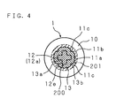
- FIG. 4 is a sectional view taken along the line IV-IV in FIG. 3;
- FIG. 5 is a sectional view showing the structure of an electric power steering apparatus according to the present invention;
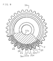
- FIG. 6 is a front view which shows, partly in section, the structure of a worm wheel of the second embodiment of a gear combination according to the present invention;
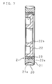
- FIG. 7 is a sectional view taken along the line VII-VII in FIG. 6;
- FIG. 8 is a front view which shows, partly in section, the structure of a worm wheel of the third embodiment of a gear combination according to the present invention;
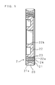
- FIG. 9 is a sectional view taken along the line IX-IX in FIG. 8; and
- FIG. 10 is a front view showing the structure of a torsion bar of an electric power steering apparatus according to the present invention.
-
- The following description will explain the present invention in detail with reference to the drawings illustrating some embodiments thereof.
- FIG. 2 is a sectional view showing the structure of the first embodiment of a gear combination according to the present invention; FIG. 3 is an enlarged sectional view showing the structure of a worm of the gear combination; and FIG. 4 is a sectional view taken along the line IV-IV in FIG. 3.
- The gear combination comprises a
worm 1 made of metal which includes ahelical tooth 10 on the outer surface thereof, and aworm wheel 2 engaged with theworm 1. - The
worm 1 is composed of: anannular tooth body 11 having atooth 10 on the outer surface thereof; acylindrical core body 12 inserted inside theannular tooth body 11; and an annularelastic coupler 13, which can be transformed in the radial direction, for coupling thecore body 12 with theannular tooth body 11. - The
annular tooth body 11 is constituted of anannular coupling portion 11b having a noncircular throughbore 11a at the inner surface thereof, and thetooth 10 formed on the outer surface of theannular coupling portion 11b through gear cutting. The throughbore 11a is, for example, formed to have an approximately cruciform section, so that relative turn between the throughbore 11a and theelastic coupler 13 is prevented. - The
core body 12 includes: a noncircular coupling shaft portion 12a;fitting shaft portions 12b and 12c extending from both ends of the coupling shaft portion 12a; and a jointing shaft portion 12d, which is jointed with a drive shaft 3a of amotor 3, extending from onefitting shaft portion 12b. Thecore body 12 is rotatably supported in ahousing 6 by twoantifriction bearings 4 and 5 fitted at thefitting shaft portions 12b and 12c. The coupling shaft portion 12a is formed to have an approximately cruciform section, by applying press forming (forging) to the outer surface of a cylindrical member and providing a plurality of approximately v-shapedconcavities 12e. Theelastic coupler 13 is provided with convexities 13a to be engaged with theconcavities 12e. Theconcavities 12e and convexities 13a constitute relative turn limiting means 200 for preventing relative turn between thecore body 12 and theelastic coupler 13. Theelastic coupler 13 is further provided withconcavities 13b formed on the outer surface thereof, and theannular coupling portion 11b is provided withconvexities 11c in correspondence to theconcavities 13b. Theconcavities 13b andconvexities 11c constitute relative turn limiting means 201 for limiting relative turn between theelastic coupler 13 and theannular coupling portion 11b. In such a manner, the relativeturn limiting means annular tooth body 11 and thecore body 12. It should be understood that the relativeturn limiting means elastic coupler 13 and the throughbore 11a, inward and/or outward in the radial direction. The shape thereof is not limited as long as relative turn between the members can be limited. - The
elastic coupler 13 is made of rubber. Theelastic coupler 13 is formed annularly by putting vulcanized rubber into a mold which houses the coaxially arrangedannular tooth body 11 andcore body 12. By this forming method, theannular tooth body 11 and thecore body 12 are bonded with each other through vulcanization. It should be understood that theelastic coupler 13 may be made of synthetic resin capable of transformation. In this case, theelastic coupler 13 is formed annularly by, for example, putting an elastomer into a mold which houses the coaxially arrangedannular tooth body 11 andcore body 12. - The
worm wheel 2 is fixed on arotary shaft 7 at a fitting bore 2a formed at a center portion thereof. Therotary shaft 7 is rotatably supported in thehousing 6 by a couple of antifriction bearings (34 and 35 in FIG. 5). - The gear combination A thus constructed is used, for example, in an electric power steering apparatus. FIG. 5 is a sectional view showing the structure of an electric power steering apparatus according to the present invention.
- The electric power steering apparatus comprises: an input shaft 9 which has an upper end connected with a
steering wheel 8 for steering and a cylindrical portion at the lower end thereof; atorsion bar 30 inserted into the cylindrical portion, which has an upper end coaxially connected with the cylindrical portion of the input shaft 9 so as to be tortile by the action of steering torque applied to thesteering wheel 8; anoutput shaft 31 which has an upper end coaxially connected with a lower end of thetorsion bar 30; atorque sensor 32 for detecting a steering torque applied to thesteering wheel 8 on the basis of the relative rotational displacement amount of the input shaft 9 and theoutput shaft 31 due to torsion of thetorsion bar 30; the steering assistmotor 3 which is driven on the basis of the torque detected by thetorque sensor 32; the gear combination A (reduction gear combination) interlocking with rotation of themotor 3, which transmits the rotation to theoutput shaft 31 in a reduced manner; and thehousing 6 which houses thetorque sensor 32 and gear combination A. Themotor 3 is attached to thehousing 6. It should be noted that theoutput shaft 31 constitutes therotary shaft 7. - The gear combination A is arranged with the
worm 1 crossing the axis of theoutput shaft 31. The jointing shaft portion 12d of theworm 1 is jointed with the drive shaft 3a of themotor 3 in such a manner that theworm 1 is supported in thehousing 6 by twoantifriction bearings 4 and 5 fitted on thefitting shaft portions 12b and 12c of thecore body 12. Movement of theworm 1 in the axial direction is prevented through relative movement of an inner race and an outer race of theantifriction bearings 4 and 5 in the axial direction made by athread ring 33 fitted in thehousing 6. - The
worm wheel 2 is supported in thehousing 6 by twoantifriction bearings output shaft 31 in the axial direction. Rotation of the drive shaft 3a is reduced by engagement of theworm 1 and theworm wheel 2, transmitted to theoutput shaft 31, and transmitted via a universal joint to a steering mechanism (which is not illustrated in the figure) of, for example, a rack-and-pinion type. It should be noted that theoutput shaft 31 and universal joint constitute transmitting means for transmitting rotation of theworm wheel 2 to the steering mechanism. Thereference number 36 in FIG. 5 indicates a bearing for supporting the input shaft 9 at thehousing 6. - In the gear combination A and the electric power steering apparatus thus constructed, the
worm 1 has anelastic coupler 13, which can be transformed in the radial direction, between theannular tooth body 11 and thecore body 12. The centre distance H between theworm 1 and theworm wheel 2 is such preset that the backlash amount at the engagement portion is smaller than, for example, a generally used initial set value by the transformation of theelastic coupler 13. Accordingly, for assembling the gear combination A, theworm 1 and theworm wheel 2 can be engaged with each other with theelastic coupler 13 of theworm 1 being transformed. When the gear combination A is assembled in such a manner, theelastic coupler 13 of theworm 1 can be transformed in the radial direction and an increase of engagement friction at the engagement portion can be depressed, so that theworm 1 andworm wheel 2 can be rotated smoothly. - When the teeth of the
worm 1 andworm wheel 2 abrade away and the backlash amount increases after long use, the backlash amount can be depressed at the same level as the generally used initial set value for an extremely long time from the beginning and the centre distance H can be maintained within a permissible range. - The
core body 12 of theworm 1 is supported at thehousing 6 by the twoantifriction bearings 4 and 5, and theannular tooth body 11 is coupled with the outer surface of thecore body 12 by theelastic coupler 13. Consequently, even if a dimensional error occurs at the fitting portion between the fitting shaft portion 12d of theworm 1 and the drive shaft 3a and at a supported portion where theworm 1 is supported at thehousing 6 by theantifriction bearings 4 and 5, the axial runout of theworm 1, i.e. the axial runout of thecore body 12, can be absorbed by theelastic coupler 13 and thereby occurrence of noise due to the axial runout can be prevented. - FIG. 6 is a front view which shows, partly in section, the structure of a worm wheel of the second embodiment of a gear combination according to the present invention; and FIG. 7 is a sectional view taken along the line VII-VII in FIG. 6.
- In the gear combination A of the second embodiment, the
worm 1 does not have the above-mentionedannular tooth body 11,core body 12 andelastic coupler 13, and the whole body thereof is integrally formed of metal. On the other hand, theworm wheel 2 of this embodiment comprises: anannular tooth body 21 made of synthetic resin having atooth 20 on the outer surface thereof; acore body 22 made of metal inserted inside theannular tooth body 21; and anelastic coupler 23 made of synthetic resin, which can be transformed in the radial direction, for coupling thecore body 22 with theannular tooth body 21. - In the second embodiment, the
core body 22 is formed in a disk shape with metal material such as low carbon steel. The outer surface of thecore body 22 is provided with a plurality of whirl-stop protrusions 22a integrally formed in a spaced manner in the peripheral direction. The center portion of thecore body 22 is provided with afitting bore 22b, which is fitted on therotary shaft 7. Theelastic coupler 23 is provided with recesses 23a to be engaged with the protrusions 22a. The protrusions 22a and recesses 23a constitute relative turn limiting means 202 for limiting relative turn between thecore body 22 and theelastic coupler 23. - The
annular tooth body 21 is formed by injecting melted synthetic resin, such as nylon resin or polyamide resin, into a mold. The formedannular tooth body 21 is coupled with thecore body 22 via theelastic coupler 23. The inner surface of theannular tooth body 21 is provided with a plurality of whirl-stop recesses 21a formed in a spaced manner in the peripheral direction. Theelastic coupler 23 is provided withprotrusions 23b to be engaged with therecesses 21a. Therecesses 21a andprotrusions 23b constitute relative turn limiting means 203 for preventing relative turn between theannular tooth body 21 and theelastic coupler 23. It should be understood that, instead of forming thetooth 20 in a mold, thetooth 20 may be formed through gear cutting after anannular element body 21 without atooth 20 is formed. - The
elastic coupler 23 is made of synthetic resin capable of transformation. Theelastic coupler 23 is formed annularly by putting an elastomer into a mold which houses the coaxially arrangedannular tooth body 21 andcore body 22. By this forming method, theelastic coupler 23 is bonded through fusion with the inner surface of theannular tooth body 21 and the outer surface of thecore body 22. It should be understood that theelastic coupler 23 may be made of rubber. In this case, for example, theelastic coupler 23 to be fitted with the inner surface of theannular tooth body 21 and the outer surface of thecore body 22 is formed, the inner surface of theannular tooth body 21 and the outer surface of thecore body 22 are coated with a primer, and the members are heated with theelastic coupler 23 being fitted between the inner surface of theannular tooth body 21 and the outer surface of thecore body 22 so that the primer is melted, to couple theelastic coupler 23 with theannular tooth body 21 and thecore body 22. - It should be also understood that the shape of the relative
turn limiting means core body 22 and theelastic coupler 23 and relative turn between theannular tooth body 21 and thecore body 22 can be limited. - In the second embodiment, the
worm wheel 2 has anelastic coupler 23, which can be transformed in the radial direction, between theannular tooth body 21 made of synthetic resin and thecore body 22 made of metal. The centre distance H between gears is such preset that the backlash amount at the engagement portion is smaller than, for example, a generally used initial set value by the transformation of theelastic coupler 23. Accordingly, for assembling the gear combination A, theworm 1 and theworm wheel 2 can be engaged with each other with theelastic coupler 23 of theworm wheel 2 being transformed. When the gear combination A is assembled in this manner, theelastic coupler 23 of theworm wheel 2 can be transformed in the radial direction and an increase of engagement friction at the engagement portion can be depressed, so that theworm 1 andworm wheel 2 can be rotated smoothly. - When the
teeth 10 of theworm 1 and theteeth 20 of theworm wheel 2 abrade away and the backlash amount increases after long use, the backlash amount can be depressed at the same level as the generally used initial set value for an extremely long time from the beginning and the centre distance H can be maintained within the permissible range. - The
annular tooth body 21 of theworm wheel 2 having thetooth 20 is made of synthetic resin having a coefficient of linear expansion larger than a coefficient of linear expansion of thecore body 22 made of metal approximately in the radio of 10 to 1. Consequently, theannular tooth body 21 expands with a rise in temperature and a rise in humidity of theworm wheel 2 due to a change in atmosphere temperature and the like, and the volume of theannular tooth body 21 increases in the radial direction. However, thetooth 20 of theannular tooth body 21 whose volume has increased is pressed against a tooth flank of theworm 1, transforming theelastic coupler 23 and theannular tooth body 21 inward in the radial direction, so that the volume increase can be partly absorbed by theelastic coupler 23, and thereby the engagement can be kept from clogging. - Since other structures and functions are the same as those of the first embodiment, like codes are used to refer to like parts and detailed explanation thereof are omitted here.
- FIG. 8 is a front view which shows, partly in section, the structure of a worm wheel of the third embodiment of a gear combination according to the present invention; and FIG. 9 is a sectional view taken along the line IX-IX in FIG. 8.
- The gear combination of the third embodiment has a
coupling ring 24 made of synthetic resin between thecore body 22 and theelastic coupler 23 in addition to the structure of theworm wheel 2 of the second embodiment. - In the third embodiment, the
coupling ring 24 is formed by injecting melted synthetic resin including the same material as theannular tooth body 21 or other similar material into a mold for injection molding which houses thecore body 22 arranged as an insert. Thecoupling ring 24 and thecore body 22 are integrally bonded. - Relative
turn limiting means 204 and 205, which are similar to the relativeturn limiting means core body 22 and thecoupling ring 24, and between thecoupling ring 24 and theelastic coupler 23. The relative turn limiting means 204 limits relative turn between thecore body 22 and thecoupling ring 24, while the relative turn limiting means 205 limits relative turn between thecoupling ring 24 and theelastic coupler 23. - The
elastic coupler 23 is formed annularly by putting an elastomer into a mold which houses the coaxially arrangedcore body 22 provided with thecoupling ring 24 and theannular tooth body 21. By this forming method, theelastic coupler 23 is bonded through fusion with the inner surface of theannular tooth body 21 and the outer surface of thecoupling ring 24. It should be understood that theelastic coupler 23 may be made of rubber as described in the second embodiment. - In the third embodiment, the
worm wheel 2 has thecoupling ring 24 made of synthetic resin, which is bonded with the outer surface of thecore body 22. Theworm wheel 2 further has theelastic coupler 23, which can be transformed in the radial direction, between the outer surface of thecoupling ring 24 and the inner surface of theannular tooth body 21 made of synthetic resin. Since theelastic coupler 23 is bonded with thecoupling ring 24 which has rigidity smaller than thecore body 22 made of metal but larger than theelastic coupler 23 and can be transformed, the binding strength between theannular tooth body 21 and thecore body 22 having theelastic coupler 23 therebetween is higher in the presence of thecoupling ring 24, and thereby the durability is enhanced. - Since other structures and functions are the same as those of the first and second embodiments, like codes are used to refer to like parts and detailed explanation thereof are omitted here.
- FIG. 10 is a front view showing the structure of a torsion bar of an electric power steering apparatus according to the present invention.
- In the electric power steering apparatus described above, the
torsion bar 30 hascoupling portions 30a and 30b provided at the ends thereof where thetorsion bar 30 is coupled with an input shaft 9 and anoutput shaft 31, and a tortile portion 30c provided between thecoupling portions 30a and 30b. Anelastic member 37 for depressing resonance of thetorsion bar 30 is provided on the outer surface of the tortile portion 30c. - The
elastic member 37 is made of elastic material, such as synthetic rubber, having damping ability. Theelastic member 37 is provided with a through bore having a diameter smaller than thecoupling portions 30a and 30b, and formed cylindrically so as to be engaged with the tortile portion 30c over approximately the total length thereof. It should be understood that theelastic member 37 may be formed by putting vulcanized rubber into a mold which houses thetorsion bar 30. - In the electric power steering apparatus thus constructed, gaps in the radial direction are formed at supported portions of the input shaft 9 and the
output shaft 31 which are supported at thehousing 6 by bearings such as thebearings 36 andantifriction bearings steering wheel 8 and the input shaft 9 andoutput shaft 31 connected with thesteering wheel 8 swing in the radial direction with vibration of the vehicle and thetorsion bar 30 connected to the input shaft 9 andoutput shaft 31 resonates while the vehicle is, for example, running a rough road, theelastic member 37 can depress the resonance of thetorsion bar 30. As a result, depression of the resonance of thetorsion bar 30 leads to a decrease of amplitude at the supported portions of the input shaft 9 and theoutput shaft 31 and to depression of rattling noise generated at the supported portions, and thereby rattling noise is not heard in the passenger's room. - The gear combination A described in the above embodiments may employ, instead of the
worm 1 as a pinion and theworm wheel 2 as a gear wheel, spur gears as a pinion and a gear wheel.
Claims (12)
- A gear comprising:an annular tooth body (11, 21) having a tooth (10, 20) on an outer surface thereof;a core body (12, 22) inserted inside the annular tooth body (11, 21); anda coupler (13, 23) made of elastic material, which couples the core body (12, 22) with the annular tooth body (11, 21).
- The gear according to Claim 1, characterized by further comprising limiting means (200 to 205) for limiting relative turn between the annular tooth body (11, 21) and the coupler (13, 23) and relative turn between the core body (12, 22) and the coupler (13, 23).
- The gear according to Claim 1 or 2, characterized in that the annular tooth body (11, 21) is made of synthetic resin and the core body (12, 22) is made of metal.
- The gear according to Claim 3, characterized in that the coupler (13, 23) is coupled with the core body (12, 22) via a coupling ring (24) made of synthetic resin having larger rigidity than the elastic material of the coupler (13, 23).
- A reduction gear combination comprising a pinion (1) and a gear wheel (2) engaged with the pinion (1),
characterized in that the pinion (1) and/or the gear wheel (2) has:an annular tooth body (11, 21) having a tooth (10, 20) on an outer surface thereof;a core body (12, 22) inserted inside the annular tooth body (11, 21); anda coupler (13, 23) made of elastic material, which couples the core body (12, 22) with the annular tooth body (11, 21). - The reduction gear combination according to Claim 5, characterized by further comprising limiting means (200 to 205) for limiting relative turn between the annular tooth body (11, 21) and the coupler (13, 23) and relative turn between the core body (12, 22) and the coupler (13, 23).
- The reduction gear combination according to Claim 5 or 6, characterized in that the annular tooth body (11, 21) is made of synthetic resin and the core body (12, 22) is made of metal.
- The reduction gear combination according to Claim 7, characterized in that the coupler (13, 23) is coupled with the core body (12, 22) via a coupling ring (24) made of synthetic resin having larger rigidity than the elastic material of the coupler (13, 23).
- An electric power steering apparatus comprising:characterized in that the pinion (1) and/or the gear wheel (2) has:a reduction gear combination (A) including a pinion (1) and a gear wheel (2) engaged with the pinion (1);a steering assist motor (3) connected with the pinion (1); andtransmitting means (31) for transmitting rotation of the gear wheel (2) associated with rotation of the motor (3) to a steering mechanism,an annular tooth body (11, 21) having a tooth (10, 20) on an outer surface thereof;a core body (12, 22) inserted inside the annular tooth body (11, 21); anda coupler (13, 23) made of elastic material, which couples the core body (12, 22) with the annular tooth body (11, 21).
- The electric power steering apparatus according to Claim 9, characterized by further comprising limiting means (200 to 205) for limiting relative turn between the annular tooth body (11, 21) and the coupler (13, 23) and relative turn between the core body (12, 22) and the coupler (13, 23).
- The electric power steering apparatus according to Claim 9 or 10, characterized in that the annular tooth body (11, 21) is made of synthetic resin and the core body (12, 22) is made of metal.
- The electric power steering apparatus according to Claim 11, characterized in that the coupler (13, 23) is coupled with the core body (12, 22) via a coupling ring (24) made of synthetic resin having larger rigidity than the elastic material of the coupler (13, 23).
Applications Claiming Priority (2)
| Application Number | Priority Date | Filing Date | Title |
|---|---|---|---|
| JP2002005364 | 2002-01-11 | ||
| JP2002005364A JP2003207029A (en) | 2002-01-11 | 2002-01-11 | Reduction gear system and electric power steering device |
Publications (3)
| Publication Number | Publication Date |
|---|---|
| EP1327569A2 true EP1327569A2 (en) | 2003-07-16 |
| EP1327569A3 EP1327569A3 (en) | 2003-09-24 |
| EP1327569B1 EP1327569B1 (en) | 2006-03-29 |
Family
ID=19191098
Family Applications (1)
| Application Number | Title | Priority Date | Filing Date |
|---|---|---|---|
| EP03000321A Expired - Lifetime EP1327569B1 (en) | 2002-01-11 | 2003-01-09 | Gear, reduction gear combination and electric power steering apparatus |
Country Status (4)
| Country | Link |
|---|---|
| US (1) | US6988582B2 (en) |
| EP (1) | EP1327569B1 (en) |
| JP (1) | JP2003207029A (en) |
| DE (1) | DE60304231T2 (en) |
Cited By (8)
| Publication number | Priority date | Publication date | Assignee | Title |
|---|---|---|---|---|
| EP1840410A2 (en) * | 2006-03-30 | 2007-10-03 | Robert Bosch Gmbh | Gear wheel |
| EP1950122A1 (en) * | 2007-01-26 | 2008-07-30 | Jtekt Corporation | Gear and electric power steering device |
| EP2020362A3 (en) * | 2007-07-30 | 2009-09-02 | IMS Gear GmbH | Electric steering device for motor vehicles |
| CN103578176A (en) * | 2012-07-19 | 2014-02-12 | 日立欧姆龙金融系统有限公司 | Paper money transaction device |
| EP2965971A3 (en) * | 2014-07-09 | 2016-02-10 | Jtekt Corporation | Electric power steering system |
| CN105793139A (en) * | 2014-03-05 | 2016-07-20 | 日本精工株式会社 | Electric power steering device and method for assembling same |
| CN105829190A (en) * | 2014-03-05 | 2016-08-03 | 日本精工株式会社 | Electric power steering device and method for assembling same |
| WO2019096469A1 (en) * | 2017-11-16 | 2019-05-23 | Robert Bosch Gmbh | Worm or toothed pinion consisting of individual parts, in the form of a globoidal worm or without globoid toothing |
Families Citing this family (31)
| Publication number | Priority date | Publication date | Assignee | Title |
|---|---|---|---|---|
| JP4586384B2 (en) * | 2004-03-08 | 2010-11-24 | 株式会社ジェイテクト | Gear manufacturing method and gear manufacturing jig |
| US20090294203A1 (en) * | 2004-08-06 | 2009-12-03 | Nsk Ltd. | electric power steering apparatus |
| DE102005035020A1 (en) | 2005-07-27 | 2007-02-01 | Zf Lenksysteme Gmbh | Radially movable floating bearing for a shaft of a steering system |
| US7721616B2 (en) * | 2005-12-05 | 2010-05-25 | Gm Global Technology Operations, Inc. | Sprung gear set and method |
| DE112007001625T5 (en) | 2006-07-12 | 2009-04-30 | Hitachi Ltd. | Power steering system, speed reduction device and storage |
| US8250940B2 (en) * | 2006-07-20 | 2012-08-28 | Steering Solutions Ip Holding Corporation | System and method for controlling contact between members in operable communication |
| JP4919154B2 (en) * | 2006-12-19 | 2012-04-18 | スズキ株式会社 | Resin gear |
| JP2008254495A (en) * | 2007-04-02 | 2008-10-23 | Jtekt Corp | Motor-driven power steering device |
| DE102007055814A1 (en) | 2007-12-14 | 2009-06-18 | Zf Lenksysteme Gmbh | Radially movable bearing |
| DE102008014402A1 (en) * | 2008-03-14 | 2009-09-17 | Volkswagen Ag | Electromechanical steering gear for use in motor vehicle, has gear rack, electric motor, and gearbox, where gearbox has belt drive with two belt pulleys and belt for coupling belt pulleys |
| EP2230071A1 (en) * | 2009-03-17 | 2010-09-22 | Quadrant Epp Ag | Composite gear blank and method for manufacturing the same |
| CN201478928U (en) * | 2009-09-01 | 2010-05-19 | 中山大洋电机股份有限公司 | Rotating shaft brake device and gear reducer motor system utilizing same |
| CN101697440B (en) * | 2009-10-30 | 2011-07-27 | 上海博泽电机有限公司 | Worm assembling method |
| JP5626576B2 (en) * | 2010-06-23 | 2014-11-19 | 株式会社ジェイテクト | Electric power steering device |
| JP5765571B2 (en) * | 2011-09-13 | 2015-08-19 | 株式会社ジェイテクト | Worm wheel |
| JP2015518122A (en) * | 2012-04-24 | 2015-06-25 | ジーケーエヌ シンター メタルズ、エル・エル・シー | Damping assembly and related manufacturing method |
| DE102014210246A1 (en) * | 2014-05-28 | 2015-12-03 | Skf Lubrication Systems Germany Gmbh | Lubricating pinion module, lubricating pinion and method of manufacturing a lubricating pinion module |
| FR3022172B1 (en) * | 2014-06-11 | 2016-05-27 | Jtekt Europe Sas | METHOD FOR MANUFACTURING A CUT-OFF WHEEL WITH A COUPLED RIM |
| USD749657S1 (en) * | 2014-11-19 | 2016-02-16 | American Axle & Manufacturing, Inc. | Gerotor housing |
| USD753743S1 (en) * | 2015-03-17 | 2016-04-12 | Nabtesco Corporation | Reduction gear |
| USD753744S1 (en) * | 2015-03-17 | 2016-04-12 | Nabtesco Corporation | Reduction gear |
| JP6624437B2 (en) * | 2015-12-24 | 2019-12-25 | 日立化成株式会社 | Manufacturing method of resin gears |
| JP6610413B2 (en) * | 2016-04-26 | 2019-11-27 | 中西金属工業株式会社 | Manufacturing method of insert molded product |
| JP2017219055A (en) * | 2016-06-03 | 2017-12-14 | Nok株式会社 | Gear Damper |
| JP2018017302A (en) * | 2016-07-27 | 2018-02-01 | Kyb株式会社 | Gear and method for manufacturing gear |
| US20190101206A1 (en) * | 2017-09-29 | 2019-04-04 | Kinematics, Llc | Integrated slew drive |
| JP7031330B2 (en) * | 2018-01-29 | 2022-03-08 | 昭和電工マテリアルズ株式会社 | Resin gears |
| WO2019164490A1 (en) * | 2018-02-22 | 2019-08-29 | Halliburton Energy Services, Inc. | Cylindrical contact polygon for torque transmission to a driveshaft |
| WO2020072289A1 (en) | 2018-10-04 | 2020-04-09 | Kinematics, Llc | Force sensing slew drive |
| JP2021011905A (en) * | 2019-07-05 | 2021-02-04 | Nok株式会社 | Gear damper and manufacturing method of gear damper |
| CN112032258A (en) * | 2020-07-24 | 2020-12-04 | 重庆大学 | Non-backlash stepped roller enveloping worm drive |
Citations (4)
| Publication number | Priority date | Publication date | Assignee | Title |
|---|---|---|---|---|
| EP0657340A1 (en) * | 1993-12-07 | 1995-06-14 | Koyo Seiko Co., Ltd. | Power steering apparatus |
| JPH092297A (en) * | 1995-06-14 | 1997-01-07 | Koyo Seiko Co Ltd | Torque limiter and motor-driven power steering gear |
| DE10119235A1 (en) * | 2000-04-20 | 2001-10-31 | Unisia Jecs Corp | Worm pinion of vehicle steering system has fiber-reinforced main body and unreinforced teeth made of same plastic |
| JP2002333059A (en) * | 2001-05-10 | 2002-11-22 | Koyo Seiko Co Ltd | Gear and electric power steering device with the same |
Family Cites Families (9)
| Publication number | Priority date | Publication date | Assignee | Title |
|---|---|---|---|---|
| US4674351A (en) * | 1985-12-23 | 1987-06-23 | Sundstrand Corporation | Compliant gear |
| JPS62166360U (en) * | 1986-04-11 | 1987-10-22 | ||
| US4831897A (en) * | 1987-10-05 | 1989-05-23 | Sundstrand Corporation | Torsionally compliant gear for use in multiple load path transmissions |
| JP2542093B2 (en) * | 1989-11-21 | 1996-10-09 | 三菱電機株式会社 | Planetary gear type reduction starter device |
| US5307705A (en) * | 1993-02-09 | 1994-05-03 | Fenelon Paul J | Stress dissipation gear and method of making same |
| US5911788A (en) * | 1998-02-20 | 1999-06-15 | Sundstrand Corporation | Compliant gear |
| JP3613693B2 (en) | 1998-07-27 | 2005-01-26 | 光洋精工株式会社 | Electric steering device |
| JP3661086B2 (en) | 2000-05-25 | 2005-06-15 | 光洋精工株式会社 | Electric steering device |
| US6551096B2 (en) * | 2000-10-03 | 2003-04-22 | Tokai Corporation | Ignition mechanism for gas lighter |
-
2002
- 2002-01-11 JP JP2002005364A patent/JP2003207029A/en active Pending
-
2003
- 2003-01-09 DE DE60304231T patent/DE60304231T2/en not_active Expired - Lifetime
- 2003-01-09 EP EP03000321A patent/EP1327569B1/en not_active Expired - Lifetime
- 2003-01-10 US US10/340,538 patent/US6988582B2/en not_active Expired - Fee Related
Patent Citations (4)
| Publication number | Priority date | Publication date | Assignee | Title |
|---|---|---|---|---|
| EP0657340A1 (en) * | 1993-12-07 | 1995-06-14 | Koyo Seiko Co., Ltd. | Power steering apparatus |
| JPH092297A (en) * | 1995-06-14 | 1997-01-07 | Koyo Seiko Co Ltd | Torque limiter and motor-driven power steering gear |
| DE10119235A1 (en) * | 2000-04-20 | 2001-10-31 | Unisia Jecs Corp | Worm pinion of vehicle steering system has fiber-reinforced main body and unreinforced teeth made of same plastic |
| JP2002333059A (en) * | 2001-05-10 | 2002-11-22 | Koyo Seiko Co Ltd | Gear and electric power steering device with the same |
Non-Patent Citations (2)
| Title |
|---|
| PATENT ABSTRACTS OF JAPAN vol. 1997, no. 05, 30 May 1997 (1997-05-30) & JP 09 002297 A (KOYO SEIKO CO LTD), 7 January 1997 (1997-01-07) * |
| PATENT ABSTRACTS OF JAPAN vol. 2003, no. 03, 5 May 2003 (2003-05-05) & JP 2002 333059 A (KOYO SEIKO CO LTD), 22 November 2002 (2002-11-22) * |
Cited By (15)
| Publication number | Priority date | Publication date | Assignee | Title |
|---|---|---|---|---|
| EP1840410A2 (en) * | 2006-03-30 | 2007-10-03 | Robert Bosch Gmbh | Gear wheel |
| EP1840410A3 (en) * | 2006-03-30 | 2009-07-15 | Robert Bosch Gmbh | Gear wheel |
| EP1950122A1 (en) * | 2007-01-26 | 2008-07-30 | Jtekt Corporation | Gear and electric power steering device |
| US8096204B2 (en) | 2007-01-26 | 2012-01-17 | Jtekt Corporation | Gear and electric power steering device |
| EP2020362A3 (en) * | 2007-07-30 | 2009-09-02 | IMS Gear GmbH | Electric steering device for motor vehicles |
| CN103578176A (en) * | 2012-07-19 | 2014-02-12 | 日立欧姆龙金融系统有限公司 | Paper money transaction device |
| EP3081458A4 (en) * | 2014-03-05 | 2017-01-25 | NSK Ltd. | Electric power steering device and method for assembling same |
| CN105793139A (en) * | 2014-03-05 | 2016-07-20 | 日本精工株式会社 | Electric power steering device and method for assembling same |
| CN105829190A (en) * | 2014-03-05 | 2016-08-03 | 日本精工株式会社 | Electric power steering device and method for assembling same |
| EP3081459A4 (en) * | 2014-03-05 | 2017-01-25 | NSK Ltd. | Electric power steering device and method for assembling same |
| US10000227B2 (en) | 2014-03-05 | 2018-06-19 | Nsk Ltd. | Electric power steering device and method for assembling the same |
| US10099718B2 (en) | 2014-03-05 | 2018-10-16 | Nsk Ltd. | Electric power steering device and method for assembling the same |
| EP2965971A3 (en) * | 2014-07-09 | 2016-02-10 | Jtekt Corporation | Electric power steering system |
| US9580101B2 (en) | 2014-07-09 | 2017-02-28 | Jtekt Corporation | Electric power steering system |
| WO2019096469A1 (en) * | 2017-11-16 | 2019-05-23 | Robert Bosch Gmbh | Worm or toothed pinion consisting of individual parts, in the form of a globoidal worm or without globoid toothing |
Also Published As
| Publication number | Publication date |
|---|---|
| EP1327569A3 (en) | 2003-09-24 |
| DE60304231T2 (en) | 2006-12-28 |
| US6988582B2 (en) | 2006-01-24 |
| EP1327569B1 (en) | 2006-03-29 |
| JP2003207029A (en) | 2003-07-25 |
| US20040084865A1 (en) | 2004-05-06 |
| DE60304231D1 (en) | 2006-05-18 |
Similar Documents
| Publication | Publication Date | Title |
|---|---|---|
| EP1327569B1 (en) | Gear, reduction gear combination and electric power steering apparatus | |
| EP1614935B1 (en) | Worm wheel and electric power steering system | |
| CN106536324B (en) | Steering shaft for motor vehicles | |
| US8459402B2 (en) | Electric power steering system | |
| US7077235B2 (en) | Electric power steering device | |
| US8602154B2 (en) | Electric power steering device | |
| JP5708981B2 (en) | Electric power steering device | |
| KR102281674B1 (en) | Reducer for vehicle | |
| JP4442421B2 (en) | Electric power steering device | |
| US8381868B2 (en) | Electric power steering system | |
| JP2006151352A (en) | Steering device | |
| JP5007591B2 (en) | Electric power steering device | |
| US20170036691A1 (en) | Shaft coupling structure and electric power steering system | |
| JP2010031929A (en) | Elastic shaft coupling and electric power steering device | |
| US7779959B2 (en) | Electric power steering apparatus | |
| JP2005319922A (en) | Power steering device | |
| KR100798513B1 (en) | Electric power steering apparatus | |
| US11148712B2 (en) | Reducer of electric power steering apparatus | |
| JP4277425B2 (en) | Electric power steering device | |
| JP4039313B2 (en) | Electric power steering device | |
| WO2005012748A1 (en) | Power transmission mechanism and electric power steering device with the mechanism assembled therein | |
| JP2011255818A (en) | Electric power steering device | |
| KR100857623B1 (en) | Structure of worm gear for electric power steering system | |
| JP3681912B2 (en) | Electric power steering device | |
| KR20110125342A (en) | Rack bar supporting device and steering apparatus for vehicle having the same |
Legal Events
| Date | Code | Title | Description |
|---|---|---|---|
| PUAI | Public reference made under article 153(3) epc to a published international application that has entered the european phase |
Free format text: ORIGINAL CODE: 0009012 |
|
| AK | Designated contracting states |
Designated state(s): AT BE BG CH CY CZ DE DK EE ES FI FR GB GR HU IE IT LI LU MC NL PT SE SI SK TR |
|
| AX | Request for extension of the european patent |
Extension state: AL LT LV MK RO |
|
| PUAL | Search report despatched |
Free format text: ORIGINAL CODE: 0009013 |
|
| AK | Designated contracting states |
Kind code of ref document: A3 Designated state(s): AT BE BG CH CY CZ DE DK EE ES FI FR GB GR HU IE IT LI LU MC NL PT SE SI SK TR |
|
| AX | Request for extension of the european patent |
Extension state: AL LT LV MK RO |
|
| 17P | Request for examination filed |
Effective date: 20040226 |
|
| AKX | Designation fees paid |
Designated state(s): DE FR GB IT |
|
| 17Q | First examination report despatched |
Effective date: 20040706 |
|
| GRAP | Despatch of communication of intention to grant a patent |
Free format text: ORIGINAL CODE: EPIDOSNIGR1 |
|
| GRAS | Grant fee paid |
Free format text: ORIGINAL CODE: EPIDOSNIGR3 |
|
| GRAA | (expected) grant |
Free format text: ORIGINAL CODE: 0009210 |
|
| AK | Designated contracting states |
Kind code of ref document: B1 Designated state(s): DE FR GB IT |
|
| PG25 | Lapsed in a contracting state [announced via postgrant information from national office to epo] |
Ref country code: IT Free format text: LAPSE BECAUSE OF FAILURE TO SUBMIT A TRANSLATION OF THE DESCRIPTION OR TO PAY THE FEE WITHIN THE PRESCRIBED TIME-LIMIT;WARNING: LAPSES OF ITALIAN PATENTS WITH EFFECTIVE DATE BEFORE 2007 MAY HAVE OCCURRED AT ANY TIME BEFORE 2007. THE CORRECT EFFECTIVE DATE MAY BE DIFFERENT FROM THE ONE RECORDED. Effective date: 20060329 |
|
| REG | Reference to a national code |
Ref country code: GB Ref legal event code: FG4D |
|
| REF | Corresponds to: |
Ref document number: 60304231 Country of ref document: DE Date of ref document: 20060518 Kind code of ref document: P |
|
| RAP2 | Party data changed (patent owner data changed or rights of a patent transferred) |
Owner name: JTEKT CORPORATION |
|
| ET | Fr: translation filed | ||
| PLBE | No opposition filed within time limit |
Free format text: ORIGINAL CODE: 0009261 |
|
| STAA | Information on the status of an ep patent application or granted ep patent |
Free format text: STATUS: NO OPPOSITION FILED WITHIN TIME LIMIT |
|
| 26N | No opposition filed |
Effective date: 20070102 |
|
| PGFP | Annual fee paid to national office [announced via postgrant information from national office to epo] |
Ref country code: GB Payment date: 20080109 Year of fee payment: 6 Ref country code: IT Payment date: 20080130 Year of fee payment: 6 |
|
| GBPC | Gb: european patent ceased through non-payment of renewal fee |
Effective date: 20090109 |
|
| PG25 | Lapsed in a contracting state [announced via postgrant information from national office to epo] |
Ref country code: GB Free format text: LAPSE BECAUSE OF NON-PAYMENT OF DUE FEES Effective date: 20090109 |
|
| PGFP | Annual fee paid to national office [announced via postgrant information from national office to epo] |
Ref country code: FR Payment date: 20100208 Year of fee payment: 8 |
|
| PGFP | Annual fee paid to national office [announced via postgrant information from national office to epo] |
Ref country code: DE Payment date: 20100107 Year of fee payment: 8 |
|
| PG25 | Lapsed in a contracting state [announced via postgrant information from national office to epo] |
Ref country code: IT Free format text: LAPSE BECAUSE OF NON-PAYMENT OF DUE FEES Effective date: 20090109 |
|
| REG | Reference to a national code |
Ref country code: FR Ref legal event code: ST Effective date: 20110930 |
|
| PG25 | Lapsed in a contracting state [announced via postgrant information from national office to epo] |
Ref country code: FR Free format text: LAPSE BECAUSE OF NON-PAYMENT OF DUE FEES Effective date: 20110131 |
|
| REG | Reference to a national code |
Ref country code: DE Ref legal event code: R119 Ref document number: 60304231 Country of ref document: DE Effective date: 20110802 |
|
| PG25 | Lapsed in a contracting state [announced via postgrant information from national office to epo] |
Ref country code: DE Free format text: LAPSE BECAUSE OF NON-PAYMENT OF DUE FEES Effective date: 20110802 |