EP1327559A1 - Parking assist apparatus for vehicle and control method of same - Google Patents
Parking assist apparatus for vehicle and control method of same Download PDFInfo
- Publication number
- EP1327559A1 EP1327559A1 EP03000456A EP03000456A EP1327559A1 EP 1327559 A1 EP1327559 A1 EP 1327559A1 EP 03000456 A EP03000456 A EP 03000456A EP 03000456 A EP03000456 A EP 03000456A EP 1327559 A1 EP1327559 A1 EP 1327559A1
- Authority
- EP
- European Patent Office
- Prior art keywords
- vehicle
- path
- driver
- steering angle
- steering
- Prior art date
- Legal status (The legal status is an assumption and is not a legal conclusion. Google has not performed a legal analysis and makes no representation as to the accuracy of the status listed.)
- Granted
Links
- 238000000034 method Methods 0.000 title claims description 32
- 230000001133 acceleration Effects 0.000 description 8
- 238000006073 displacement reaction Methods 0.000 description 6
- 238000010586 diagram Methods 0.000 description 5
- 230000007935 neutral effect Effects 0.000 description 4
- 230000001172 regenerating effect Effects 0.000 description 4
- 230000035807 sensation Effects 0.000 description 4
- 230000005540 biological transmission Effects 0.000 description 1
- 239000012141 concentrate Substances 0.000 description 1
- 230000000694 effects Effects 0.000 description 1
- 238000012544 monitoring process Methods 0.000 description 1
Images


Classifications
-
- B—PERFORMING OPERATIONS; TRANSPORTING
- B60—VEHICLES IN GENERAL
- B60Q—ARRANGEMENT OF SIGNALLING OR LIGHTING DEVICES, THE MOUNTING OR SUPPORTING THEREOF OR CIRCUITS THEREFOR, FOR VEHICLES IN GENERAL
- B60Q9/00—Arrangement or adaptation of signal devices not provided for in one of main groups B60Q1/00 - B60Q7/00, e.g. haptic signalling
- B60Q9/002—Arrangement or adaptation of signal devices not provided for in one of main groups B60Q1/00 - B60Q7/00, e.g. haptic signalling for parking purposes, e.g. for warning the driver that his vehicle has contacted or is about to contact an obstacle
- B60Q9/004—Arrangement or adaptation of signal devices not provided for in one of main groups B60Q1/00 - B60Q7/00, e.g. haptic signalling for parking purposes, e.g. for warning the driver that his vehicle has contacted or is about to contact an obstacle using wave sensors
-
- B—PERFORMING OPERATIONS; TRANSPORTING
- B62—LAND VEHICLES FOR TRAVELLING OTHERWISE THAN ON RAILS
- B62D—MOTOR VEHICLES; TRAILERS
- B62D15/00—Steering not otherwise provided for
- B62D15/02—Steering position indicators ; Steering position determination; Steering aids
- B62D15/027—Parking aids, e.g. instruction means
- B62D15/0285—Parking performed automatically
-
- B—PERFORMING OPERATIONS; TRANSPORTING
- B62—LAND VEHICLES FOR TRAVELLING OTHERWISE THAN ON RAILS
- B62D—MOTOR VEHICLES; TRAILERS
- B62D15/00—Steering not otherwise provided for
- B62D15/02—Steering position indicators ; Steering position determination; Steering aids
- B62D15/029—Steering assistants using warnings or proposing actions to the driver without influencing the steering system
-
- B—PERFORMING OPERATIONS; TRANSPORTING
- B60—VEHICLES IN GENERAL
- B60T—VEHICLE BRAKE CONTROL SYSTEMS OR PARTS THEREOF; BRAKE CONTROL SYSTEMS OR PARTS THEREOF, IN GENERAL; ARRANGEMENT OF BRAKING ELEMENTS ON VEHICLES IN GENERAL; PORTABLE DEVICES FOR PREVENTING UNWANTED MOVEMENT OF VEHICLES; VEHICLE MODIFICATIONS TO FACILITATE COOLING OF BRAKES
- B60T2201/00—Particular use of vehicle brake systems; Special systems using also the brakes; Special software modules within the brake system controller
- B60T2201/10—Automatic or semi-automatic parking aid systems
Definitions
- the invention relates to a parking apparatus for a vehicle that assists with driving of the vehicle to a target parking position by automatic steering.
- the steering angle is returned to the neutral position before the vehicle starts moving in order to make the initial steering angle when regenerating the steering wheel operation match the initial steering angle of when the steering wheel operation was recorded.
- the steering angle may be great at the start-parking position.
- the steering wheel is automatically turned suddenly before the vehicle starts to move, thereby possibly giving an inexperienced driver an unpleasant sensation.
- the steering wheel is turned while the vehicle is stopped, i.e., so-called stationary steering, more force is required to turn the steering wheel than is required when turning the steering wheel while the vehicle is moving.
- the parking position after regenerating the steering wheel operation differs increasingly from the target position the greater the distance between the target parking position and the start-parking position. In this difference, the effect of the difference in the direction of the vehicle is particularly great.
- a parking assist apparatus which is one aspect of the invention and which assists with moving a vehicle by automatic steering from an arbitrary stopping position to a target parking position, is provided with a setting portion and an instruction portion.
- the setting portion sets a path from the stopping position to the target parking position, as well as sets the steering operation necessary for the vehicle to follow that path.
- the instruction portion issues an instruction so as to instruct the driver to turn the steering wheel to other steering angle.
- the setting portion calculates another initial stopping position where the path to the target parking position can be set.
- the instruction portion then issues an instruction so as to instruct the driver to move the vehicle to the other initial stopping position.
- the parking assist apparatus may further be provided with a notification portion that notifies driver when the path from the current position to the target parking position is able to be set.
- a control method of the parking assist apparatus includes the steps of determining whether the path to the target parking position with the current steering angle can be set; calculating, when the path cannot be set, another steering angle where the path can be set; and instructing the driver to turn the steering wheel to the other steering angle where the path can be set.
- control method of the parking assist apparatus may further include the steps of calculating another initial stopping position where the path to the target parking position can be set when the other steering angle where the path can be set cannot be calculated; instructing the driver to move the vehicle to the other initial stopping position; and notifying the driver when the vehicle has reached the other initial stopping position.
- the vehicle is able to reliably reach the target parking position even without the driver accurately setting the stopping position and initial steering angle, thereby simplifying the parking operation. Also, because the driver sets the other initial steering angle, there is no unpleasant sensation in the operation. Further, there is little load on the steering system and the steering force required of the automatic steering apparatus is little, thereby enabling the cost of the automatic steering apparatus to be reduced.
- the setting portion calculates another initial stopping position where the path to the target parking position can be set and the instructing means instructs the driver to move the vehicle to the obtained other initial stopping position.
- the parking assist system be provided with notification portion for notifying the driver when it has become possible to set the path from the current position to the target position. This further lightens the load on the driver while moving the vehicle.
- FIG. 1 is a block diagram of a parking assist apparatus 100 according to one exemplary embodiment of the invention.
- This parking assist apparatus 100 includes a driving control apparatus 110 and an automatic steering apparatus 120.
- the parking assist apparatus 100 is controlled by a parking assist ECU 1, which serves as a control apparatus.
- the parking assist ECU 1 also serves as a setting portion as setting means according to this invention.
- the driving control portion 10 and steering control portion 11 may be categorized as hardware within the parking assist ECU 1, or as software which uses the same CPU, ROM, RAM and the like as hardware.
- the driving control apparatus 110 includes the driving control portion 10, a brake system, and a drive system.
- the brake system is an electronically controlled brake (ECB) system that electronically controls braking force applied to each wheel with a brake ECU 31.
- EEB electronically controlled brake
- This brake system uses an actuator 34 to adjust the braking force by adjusting a brake hydraulic pressure that is applied to wheel cylinders 38 of a hydraulic brake disposed in each wheel.
- Output signals from wheel speed sensors 32, an acceleration sensor 33, a group of hydraulic pressure sensors, and a master cylinder (M/C) hydraulic pressure sensor 36 are input to the brake ECU 31.
- the wheel speed sensors 32 are disposed in the wheels and detect a wheel speed thereof.
- the acceleration sensor 33 detects an acceleration of the vehicle.
- the group of hydraulic sensors, not shown, is disposed in the actuator 34, and detect a hydraulic pressure that is applied within the actuator 34 as well as to the wheel cylinders 38.
- the master cylinder (M/C) hydraulic pressure sensor 36 detects a hydraulic pressure of the master cylinder 35 that is disposed between the brake pedal 37 and the actuator 34.
- An engine 22 that forms the drive system is controlled by an engine ECU 21.
- the engine ECU 21 and the brake ECU 31 control in cooperation by communicating with the driving control portion 10.
- an output from a shift sensor 12 that detects a shift state of a transmission is input to the engine ECU 21.
- the automatic steering apparatus 120 is provided with a driving motor 42, which also serves as a power steering apparatus provided between a steering wheel 40 and a steering gear 41, and a displacement sensor 43 that detects a displacement amount in the steering.
- the steering control portion 11 of the automatic steering apparatus 120 controls the driving of the driving motor 42 and receives an output signal from the displacement sensor 43.
- a speaker 14 that provides information by voice and a monitor 13 are connected to the parking assist ECU 1 includes the driving control portion 10 and the steering control portion 20.
- the monitor 13 receives both an image signal from a back camera 15 that captures an image of an area in back of the vehicle, and an output signal from input means 16 that receives operational input by the driver when parking assist is performed.
- the monitor 13 then refers that information to the driver via an image.
- the monitor 13 and the back camera 15 each make up an instruction portion as instructing means and an notification portion as notifying means.
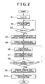
- FIG. 2 is a flowchart illustrating in detail the actual entire parking assist routine.
- FIG. 3 is a flowchart illustrating in detail a process within the routine shown in FIG. 2 for setting a path for parking.
- FIGS. 4 and 5 are diagrams illustrating paths of the vehicle during this parking assist.
- a vehicle 5 is being backed into a garage 7 that faces a road 6 will be described.
- the vehicle 5 is moved into a position for starting a parking operation (hereinafter, referred to as "parking-start position"), shown in FIG. 4.
- the driver then puts the vehicle 5 in a parking assist mode by operating the input means 16 while looking at the image captured by the back camera 15 that is displayed on the monitor 13.
- the driver then sets the target parking position by moving the parking frame on the screen of the monitor 13 to a position denoted by 5t in the figure.
- the center point of the vehicle shall be denoted P(X, Y) and the center point of the target parking position 5t shall be denoted Pt(Xt, Yt).
- step S1 the parking assist ECU 1 sets a path-to-parking-position-setting-complete flag Xset (hereinafter, simply referred to as "path setting complete flag Xset") to 0 as the initial value.
- path setting complete flag Xset 1 it means that the path leading to the target position 5t has been set, and when the path setting complete flag Xset is 0 is means that the path has not been set.
- step S2 the parking assist ECU 1 executes the process to set the path leading to the target position. Then in step S3, the parking assist ECU 1 checks the value of the path setting complete flag Xset. When the value of the path setting complete flag Xset is 1 the process proceeds on to step S4, but when the value of the path setting complete flag Xset is 0 the process returns to step S2 and the path is set.
- FIG. 3 illustrates in detail the contents of the process to set the path leading to the target position in step S2 in FIG. 2.
- the parking assist ECU 1 obtains the path from the current position P(X, Y) to Pt(Xt, Yt). More specifically, an image recognition process is first executed to obtain the Pt(Xt, Yt) beforehand.
- the target position Pt(Xt, Yt) may be obtained as relative coordinates that have the current vehicle position P(X, Y) as the point of origin, for example.
- the parking assist ECU 1 obtains the path 8n of the center point of the vehicle that is optimal for leading from P(X, Y) to the target position Pt(Xt, Yt). At this time, a steering angle and steering operation amount with respect to the path that are able to be set by the automatic steering apparatus 120 are calculated.
- step S202 it is determined whether the path can be set.
- the path when the steering position is maintained in the neutral position is set as shown by a solid line 8n.
- a path having a smaller turning radius than the path shown by the solid line 8n can be taken, as shown by a chain line 8r.
- the process has succeeded in setting the path so the process proceeds on to step S203, where the parking assist ECU 1 sets the path setting complete flag Xset to 1, after which the path setting process ends.
- the path of the vehicle 5 would change to one that nears the target point Pt(Xt, Yt), as shown by a broken line 81. If the vehicle 5 were to follow this path shown by the broken line 81, however, the vehicle 5 would contact the edge of the garage 7 at the position Px(Xx, Yx) midway to the target position, thereby preventing the vehicle 5 from being able to be parked in the target position by taking that path. In this case, the parking assist ECU 1 determines in step S202 that the path is unable to be set and the process proceeds on to step S204.
- step S204 it is determined whether the vehicle is currently moving.
- the process proceeds on to step S205, where the parking assist ECU 1 determines whether the initial steering angle can be changed. This is determined by whether the steering wheel can be turned to the side where Px will approach the target point Pt, i.e., to the Pt side when viewed from Px.
- step S206 the initial steering angle is changed to the determined side (i.e., the side near the target position Pt side) by a predetermined amount.
- step S207 the parking assist ECU 1 recalculates the path to the target parking position Pt with the changed initial steering angle.
- step S208 it is determined whether it is possible to set the recalculated path.
- the process returns to step S205, where it is determined whether the vehicle 5 can be moved to the parking position from the current position by changing the steering angle.
- step S208 when it has been determined in step S208 that the path of the vehicle 5 to the parking position can be set by changing the steering angle, the process proceeds on to step S209.
- step S209 the parking assist ECU 1 instructs the driver to change the initial steering angle the necessary amount to follow the obtained path by giving the driver directions such as, "Turn the steering wheel one-half rotation to the right.” using the monitor 13 and the speaker 14. Then the process ends.
- step S203 the path setting complete flag Xset will not be set to 1 until the steering angle has actually changed, after which the processes in step S201, step S202, and step S204 through step S209 are executed.
- the driver can more reliably change the initial steering angle to a steering angle which will enable the vehicle 5 to reach the target position Pt. Because this so-called "stationary steering" is done by the driver, only a small amount of driving force is needed from the driving motor 42 of the automatic steering apparatus 120, so the load on the steering system is able to be reduced. At this time, it is preferable that the driving motor 42 perform a power steering operation that will assist the steering operation by the driver. Further, because the driver is performing the steering operation, the steering wheel will not suddenly turn by itself when the vehicle 5 stops, such as with the art in Japanese Patent Laid-Open Publication No. 3-14767, and thereby does not give the driver an unpleasant sensation.
- step S210 When the vehicle 5 is unable to reach the target parking position even with the steering wheel turned all the way to the parking position side, i.e., when it has been determined that the steering angle cannot be changed in step S205 after it has been determined that the path is unable to be set in step S202 or step S208, and when the vehicle 5 is moving, the process proceeds on to step S210.
- This is a case in which it is determined that parking is not possible due to the fact that the vehicle 5 will contact the edge of the garage 7 at a position Pa(Xa, Ya) even if it is headed toward the target parking position 5t along a path 8r' which has the smallest turning radius from a current position P'(x', y') as shown in FIG. 5.
- step S210 the parking assist ECU 1 calculates a target path 8t along which it is possible for the vehicle 5 to reach the target parking position Pt using the smallest turning radius by a reverse operation from the target parking position Pt.
- step S211 the parking assist ECU 1 obtains both a path 8s that leads to the target path 8t from the current position P'(x', y') and a point Ps(Xs, Ys) where that path 8s intersects with the target path 8t.
- this path 8s be obtained as an extension when the vehicle 5 proceeds with the current steering angle as it is or when the vehicle 5 proceeds with the steering wheel returned to the neutral position.
- step S212 the parking assist ECU 1 instructs the driver to move the vehicle 5 the necessary amount to follow the obtained path by giving the driver directions such as, "Move the vehicle ahead five meters.” using the monitor 13 and the speaker 14. Then the process ends.
- the parking assist ECU 1 may give the driver directions such as, "While returning the steering wheel to the right, move the vehicle ahead five meters.”
- step S203 the path setting complete flag Xset will not be set to 1 until the steering angle has actually changed, after which the processes in step S201, step S202, step S204, and steps S211 and S212 are executed. Accordingly, the driver is able to reliably move the vehicle 5 to an initial position from which it is possible for the vehicle to reach the target position Pt.
- the driver be notified by voice as to the state of the vehicle 5 while changing the steering angle or moving the vehicle 5.
- the driver may be given directions such as, "Continue turning the steering wheel for one-half rotation.”
- the driver may be given directions such as, "Continue for three more meters.”
- the driver is able to reliably operate the vehicle 5 to the obtained initial state.
- the parking assist ECU 1 determines whether the automatic parking assist is possible by stationary steering with the vehicle 5 in that stopping position, and recalculates the path to the initial position in the event that the course has been changed partway through. Accordingly, it is possible to reliably guide the driver to an initial position and initial steering angle where parking assist is possible.
- the path setting complete flag Xset is set to 1 and the process proceeds from step S3 to step S4.
- step S4 the driver is instructed to depress the brake pedal 37 and operate the shift lever so as to put the vehicle 5 into reverse.
- the parking assist apparatus stands-by until these conditions have been fulfilled.
- step S5 the driving control portion 10 of the parking assist ECU 1 instructs the engine ECU 21 to increase the torque of the engine 22 and begins automatic steering. With this increase in torque, the rotation speed of the engine 22 becomes higher than when it is idling normally, so the engine 22 shifts to a torque increased state with a high driving force.
- the vehicle speed range adjustable by operation of only the brake pedal 37 expands without the driver operating the accelerator, thus controllability of the vehicle is improved.
- a wheel cylinder hydraulic pressure i.e., brake hydraulic pressure
- the actuator 34 adjusts the vehicle speed according to the pedal depression amount of the brake pedal 37, such that the braking force applied to each wheel is adjusted, thereby adjusting the vehicle speed.
- the brake hydraulic pressure applied to each of the wheel cylinders 38 is adjusted by the actuator 34 such that the vehicle speed detected by the wheel speed sensor 32 does not exceed the upper limit vehicle speed, i.e., braking force is applied to guard the upper limit vehicle speed.
- the brake ECU 31 controls the actuator 34 such that a corresponding braking force is applied to the wheel cylinders 38, thus enabling the vehicle to be slowed and stopped safely.
- step S6 the current position is calculated based on the change in the vehicle speed, the change in the acceleration, and the change in the steering angle.
- the change in the vehicle speed is obtained based on the wheel speed which is obtained by the wheel speed sensor 32.
- the change in the acceleration is obtained based on the acceleration which is obtained by the acceleration sensor 33.
- the change in the steering angle is obtained by the displacement sensor 43.
- the steering control portion 11 controls the driving motor 42 to operate the steering gear 41 while monitoring the output of the displacement sensor 43 such that the steering angle matches a steering angle displacement in accordance with the position obtained by the parking assist ECU 1 (step S7).
- step S8 it is determined whether the current position P (i.e., the vehicle 5) has reached the target position Pt. For this determination, it may be determined whether the current position P is within a predetermined area somewhere around the target position Pt. The extent of that area may be set based on the accuracy of the image recognition of the image captured by the back camera 15, the determination accuracy of the current position obtained by the vehicle speed, acceleration and the like, and the steering accuracy of the automatic steering apparatus 120 and the like.
- the process returns to step S6 and repeats. Accordingly, the driver is able to move the vehicle 5 along the set path to the target position Pt without having to turn the steering wheel. Also, the driver is able to concentrate on checking the safety of the path ahead of the vehicle and adjusting the vehicle speed, thus simplifying the parking operation.
- step S9 the driving control portion 10 instructs the engine ECU 21 to decrease the rotation speed of the engine 22, thereby reducing torque, and the steering control portion 11 ends automatic steering control.
- step S10 the parking assist ECU 1 notifies the driver via the monitor 13 and speaker 14 that the vehicle 5 has reached the target parking position, and prompts the driver to set the shift lever in the park position and turn off the engine, after which the routine ends.
- the system may notify the driver of that via the speaker 14 and prompt the driver to change the initial position. In this case as well, it is preferable to determine whether the path from the current position to the set target parking position is possible and inform the driver when it becomes possible while the vehicle is moving.
- the initial steering angle with which the vehicle can reach the target parking position is obtained and the driver is prompted to change the steering angle to that initial steering angle. Accordingly, the vehicle is able to reliably reach the target parking position without increasing the load on the steering system.
Landscapes
- Engineering & Computer Science (AREA)
- Transportation (AREA)
- Mechanical Engineering (AREA)
- Chemical & Material Sciences (AREA)
- Combustion & Propulsion (AREA)
- Radar, Positioning & Navigation (AREA)
- Remote Sensing (AREA)
- Human Computer Interaction (AREA)
- Steering Control In Accordance With Driving Conditions (AREA)
Abstract
Description
Claims (10)
- A parking assist apparatus for a vehicle, which assists a driver with moving the vehicle from an arbitrary stopping position to a target parking position by automatic steering, the parking assist apparatus characterized by comprising:a setting means (1) for setting a path from the stopping position to the target parking position and a steering wheel operation necessary for guiding the vehicle along that path; andan instruction means (13,14) for instructing the driver to turn the steering wheel to the other steering angle when the setting means (1) determines that the path cannot be set with a steering angle in the stopping position and the path can be set with another steering angle.
- The parking assist apparatus according to claim 1, characterized in that:the setting means (1) for calculating, when the setting means (1) has determined that the path from the stopping position to the target parking position (Pt) cannot be set even if the steering angle in the stopping position is changed, another initial stopping position (Ps) where the path (8n) to the target parking position (Pt) can be set; andthe instruction means (13,14) issues an instruction so as to instruct the driver to move the vehicle to the other initial stopping position.
- The parking assist apparatus according to claim 2, characterized in that:the setting means (1) monitors a position of the vehicle (5) moved by the driver after the instruction has been given,
further comprisinga notification means (13,14) for notifying the driver when the vehicle position has reached the other initial stopping position (Ps). - The parking assist apparatus according to claim 2, characterized in that:the other initial stopping position (Ps) is a position where the vehicle (5) can reach the target parking position (Pt) with the shortest turning radius of the vehicle (5).
- The parking assist apparatus according to any one of claims 1 to 4, characterized in that:the instruction means (13,14) is at least one of a monitor (13) and a speaker (14).
- The parking assist apparatus according to claim 3, characterized in that:the notification means (13,14) is at least one of a monitor (13) and a speaker (14).
- The parking assist apparatus according to any one of claims 1 to 7, characterized in that:the setting means (1) instructs the engine of the vehicle to increase torque when the vehicle moves along the path.
- A control method of a parking assist apparatus for a vehicle, which assists a driver with moving the vehicle from an arbitrary stopping position to a target parking position by automatic steering, the control method characterized by comprising the steps of:determining whether a path (8n) to the target parking position (Pt) can be set with a current steering angle;calculating (S202), when the path (8n) cannot be set, another steering angle that can be set; andinstructing (S209) the driver to turn a steering wheel to the other steering angle that can be set.
- The control method according to claim 8, characterized by further comprising the steps of:calculating (S210) another initial stopping position (Ps) where the path to the target parking position (Pt) can be set when the other steering angle that can be set cannot be calculated; andinstructing (S212) the driver to move the vehicle to the another initial stopping position (Ps).
- The control method according to claim 9, characterized by further comprising the step of:notifying (S10) the driver that the vehicle (5) has reached the other initial stopping position (S10).
Applications Claiming Priority (2)
| Application Number | Priority Date | Filing Date | Title |
|---|---|---|---|
| JP2002005072A JP3749483B2 (en) | 2002-01-11 | 2002-01-11 | Parking assistance device |
| JP2002005072 | 2002-01-11 |
Publications (2)
| Publication Number | Publication Date |
|---|---|
| EP1327559A1 true EP1327559A1 (en) | 2003-07-16 |
| EP1327559B1 EP1327559B1 (en) | 2008-03-26 |
Family
ID=19191061
Family Applications (1)
| Application Number | Title | Priority Date | Filing Date |
|---|---|---|---|
| EP03000456A Expired - Lifetime EP1327559B1 (en) | 2002-01-11 | 2003-01-10 | Parking assist apparatus for vehicle and control method of same |
Country Status (4)
| Country | Link |
|---|---|
| US (1) | US6929082B2 (en) |
| EP (1) | EP1327559B1 (en) |
| JP (1) | JP3749483B2 (en) |
| DE (1) | DE60319895T2 (en) |
Cited By (11)
| Publication number | Priority date | Publication date | Assignee | Title |
|---|---|---|---|---|
| EP1510441A3 (en) * | 2003-08-29 | 2005-05-25 | Aisin Seiki Kabushiki Kaisha | Parking assist device |
| EP1500950A3 (en) * | 2003-07-23 | 2005-12-14 | Toyota Jidosha Kabushiki Kaisha | Parking-assist device and reversing-assist device |
| EP1533181A3 (en) * | 2003-11-22 | 2006-05-31 | Robert Bosch Gmbh | Device for the semiautomatique support for parking a vehicle |
| EP1626384A3 (en) * | 2004-08-12 | 2007-03-28 | Robert Bosch GmbH | Parking assistance system for a vehicle and method for assisting a vehicle user when parking a vehicle |
| EP1695888A3 (en) * | 2005-02-23 | 2008-04-16 | Robert Bosch Gmbh | Device for semi-autonomous parking assistance of vehicles |
| EP1602560A3 (en) * | 2004-06-03 | 2008-06-04 | Magna Donnelly GmbH & Co. KG | Vehicle steering aid - apparatus and method |
| CN100414467C (en) * | 2003-08-29 | 2008-08-27 | 爱信精机株式会社 | parking aid |
| EP2330014A1 (en) * | 2009-12-04 | 2011-06-08 | Robert Bosch GmbH | Parking system for a motor vehicle |
| EP2003021A4 (en) * | 2006-03-31 | 2012-07-04 | Aisin Seiki | Parking assistance device |
| GB2543094A (en) * | 2015-10-09 | 2017-04-12 | Jaguar Land Rover Ltd | Method and apparatus for aligning a vehicle with a wireless charging device |
| US20250083664A1 (en) * | 2023-09-13 | 2025-03-13 | Panasonic Automotive Systems Co., Ltd. | Parking support method, parking support apparatus, and computer-readable recording medium |
Families Citing this family (38)
| Publication number | Priority date | Publication date | Assignee | Title |
|---|---|---|---|---|
| JP4058369B2 (en) * | 2003-03-27 | 2008-03-05 | トヨタ自動車株式会社 | Parking assistance device |
| JP4235026B2 (en) * | 2003-04-28 | 2009-03-04 | トヨタ自動車株式会社 | Parking assistance device |
| DE10336985A1 (en) * | 2003-08-12 | 2005-03-10 | Daimler Chrysler Ag | Method for assisting the driver in driving maneuvers |
| US7229139B2 (en) * | 2004-03-18 | 2007-06-12 | Ford Global Technologies, Llc | Control system for brake-steer assisted parking and method therefor |
| US20050206231A1 (en) * | 2004-03-18 | 2005-09-22 | Ford Global Technologies, Llc | Method and apparatus for controlling an automotive vehicle using brake-steer and normal load adjustment |
| US8380416B2 (en) | 2004-03-18 | 2013-02-19 | Ford Global Technologies | Method and apparatus for controlling brake-steer in an automotive vehicle in reverse |
| US7165644B2 (en) * | 2004-03-18 | 2007-01-23 | Ford Global Technologies, Llc | Method and apparatus of controlling an automotive vehicle using brake-steer as a function of steering wheel torque |
| JP3977368B2 (en) * | 2004-09-30 | 2007-09-19 | クラリオン株式会社 | Parking assistance system |
| JP4020128B2 (en) * | 2005-04-22 | 2007-12-12 | トヨタ自動車株式会社 | Target position setting device and parking support device having the same |
| CN101171153B (en) * | 2005-05-11 | 2010-05-12 | 株式会社日立制作所 | Communication and control devices in cars and in cars |
| DE102005027165B4 (en) * | 2005-06-13 | 2024-01-25 | Robert Bosch Gmbh | Method and device for issuing parking instructions |
| WO2006136665A1 (en) * | 2005-06-24 | 2006-12-28 | Renault Trucks | Method for controlling the steering angle of the vehicle guiding wheels |
| DE112006002182B4 (en) * | 2005-08-18 | 2010-08-05 | Sauer-Danfoss Aps | A method of calibrating a steering system and steering a vehicle with a positioning system |
| JP4414959B2 (en) * | 2005-11-16 | 2010-02-17 | アイシン精機株式会社 | Parking assistance device |
| US8538631B2 (en) * | 2007-01-23 | 2013-09-17 | GM Global Technology Operations LLC | Method and system for vehicle parking assistance |
| DE102007009745A1 (en) * | 2007-02-28 | 2008-09-04 | Continental Automotive Gmbh | Method for controlling vehicle steering during parking process, involves measuring parking place selected for parking vehicle and establishing orientation field, where orientation field determines number of support points |
| US7737866B2 (en) * | 2007-09-27 | 2010-06-15 | Automotive Research & Testing Center | Auto-parking device |
| DE102008027779A1 (en) * | 2008-06-11 | 2009-12-17 | Valeo Schalter Und Sensoren Gmbh | Method for assisting a driver of a vehicle when parking in a parking space |
| KR101332932B1 (en) | 2009-02-26 | 2013-11-26 | 아이신세이끼가부시끼가이샤 | Parking assistance device |
| DE102009028309B4 (en) * | 2009-08-06 | 2019-06-27 | Robert Bosch Gmbh | A method for assisting parking a vehicle out of a parking space and device for this purpose |
| DE102010020204A1 (en) * | 2010-05-12 | 2011-11-17 | Volkswagen Ag | Method for parking a vehicle and corresponding parking assistance system and vehicle |
| DE102010031672A1 (en) * | 2010-07-22 | 2012-01-26 | Robert Bosch Gmbh | Method for assisting a driver of a motor vehicle |
| DE102011003881A1 (en) * | 2011-02-09 | 2012-08-09 | Robert Bosch Gmbh | Method for assisting a driver of a motor vehicle |
| DE102012012265A1 (en) * | 2012-06-20 | 2013-12-24 | Audi Ag | Method for operating a motor vehicle comprising a parking assistance system |
| JP6187781B2 (en) * | 2012-11-06 | 2017-09-06 | パナソニックIpマネジメント株式会社 | Parking assistance device |
| CN104781123B (en) * | 2012-11-27 | 2016-08-24 | 日产自动车株式会社 | Vehicle is with accelerating restraining device and vehicle with accelerating suppressing method |
| KR20150042106A (en) * | 2013-10-10 | 2015-04-20 | 현대자동차주식회사 | Shifting apparatus for vehicle |
| US9434415B2 (en) * | 2013-11-08 | 2016-09-06 | Ford Global Technologies, Llc | Tire windup compensation |
| JP2014199057A (en) * | 2014-06-27 | 2014-10-23 | トヨタ自動車株式会社 | Vehicle control device |
| JP6049811B1 (en) * | 2015-06-23 | 2016-12-21 | 三菱電機株式会社 | Automatic parking control device |
| JP6594736B2 (en) * | 2015-10-27 | 2019-10-23 | クラリオン株式会社 | Parking assistance device |
| JP6911434B2 (en) * | 2017-03-23 | 2021-07-28 | 株式会社アイシン | Vehicle running support device |
| CN107416023B (en) * | 2017-08-04 | 2019-04-12 | 奇瑞汽车股份有限公司 | It parks method and apparatus |
| DE102018205968A1 (en) * | 2018-04-19 | 2019-10-24 | Volkswagen Aktiengesellschaft | Method for operating a parking assistance system of a motor vehicle and parking assistance system for a motor vehicle |
| CN110626259A (en) * | 2018-06-21 | 2019-12-31 | 鸿富锦精密电子(天津)有限公司 | Triangular warning frame and collision early warning method thereof |
| US11247724B2 (en) * | 2019-08-16 | 2022-02-15 | Ford Global Technologies, Llc | Vehicle parking control |
| DE102021206708B4 (en) * | 2021-06-29 | 2023-05-11 | Continental Autonomous Mobility Germany GmbH | Method for replanning a parking trajectory |
| JP2024140018A (en) * | 2023-03-28 | 2024-10-10 | パナソニックオートモーティブシステムズ株式会社 | Driving assistance device and driving assistance method |
Citations (6)
| Publication number | Priority date | Publication date | Assignee | Title |
|---|---|---|---|---|
| JPH0314767A (en) * | 1989-06-08 | 1991-01-23 | Fuji Heavy Ind Ltd | Motor-driven power steering device for car working also as auto-steering device |
| JPH11208420A (en) * | 1998-01-27 | 1999-08-03 | Nissan Motor Co Ltd | Parking guidance device and automatic parking device |
| US6275754B1 (en) * | 1996-10-09 | 2001-08-14 | Honda Giken Kogyo Kabushiki Kaisha | Automatic steering system for vehicle |
| WO2001085496A1 (en) * | 2000-05-12 | 2001-11-15 | Kabushiki Kaisha Toyota Jidoshokki | Vehicle backing support apparatus |
| EP1160146A2 (en) * | 2000-05-30 | 2001-12-05 | Aisin Seiki Kabushiki Kaisha | Parking assistor |
| EP1170171A2 (en) * | 2000-07-03 | 2002-01-09 | Toyota Jidosha Kabushiki Kaisha | Vehicle-parking assisting system |
Family Cites Families (11)
| Publication number | Priority date | Publication date | Assignee | Title |
|---|---|---|---|---|
| US4931930A (en) * | 1988-04-19 | 1990-06-05 | Industrial Technology Research Institute | Automatic parking device for automobile |
| JP3645969B2 (en) | 1996-10-09 | 2005-05-11 | 本田技研工業株式会社 | Automatic vehicle steering system |
| DE19703517C2 (en) * | 1997-01-31 | 2001-05-31 | Daimler Chrysler Ag | Method for displaying the control interventions for parking a motor vehicle or method for carrying out the control interventions for parking a motor vehicle and device for carrying out the method |
| JP3223244B2 (en) * | 1997-04-15 | 2001-10-29 | 本田技研工業株式会社 | Automatic vehicle steering system |
| JP3044534B2 (en) * | 1997-04-28 | 2000-05-22 | 本田技研工業株式会社 | Automatic vehicle steering system |
| JP3498582B2 (en) * | 1998-08-26 | 2004-02-16 | トヨタ自動車株式会社 | Parking assistance device |
| JP4129101B2 (en) * | 1999-07-02 | 2008-08-06 | 本田技研工業株式会社 | Automatic vehicle steering system |
| WO2001012472A1 (en) * | 1999-08-12 | 2001-02-22 | Kabushiki Kaisha Toyoda Jidoshokki Seisakusho | Steering assist device |
| JP2001106115A (en) | 1999-10-04 | 2001-04-17 | Yazaki Corp | Pointing device in parking assist system and computer-readable recording medium recording the pointing program |
| JP3575365B2 (en) * | 1999-12-28 | 2004-10-13 | 株式会社豊田自動織機 | Steering support device for parallel parking |
| JP2002036991A (en) * | 2000-07-27 | 2002-02-06 | Honda Motor Co Ltd | Parking assistance device |
-
2002
- 2002-01-11 JP JP2002005072A patent/JP3749483B2/en not_active Expired - Lifetime
-
2003
- 2003-01-06 US US10/336,407 patent/US6929082B2/en not_active Expired - Fee Related
- 2003-01-10 EP EP03000456A patent/EP1327559B1/en not_active Expired - Lifetime
- 2003-01-10 DE DE60319895T patent/DE60319895T2/en not_active Expired - Lifetime
Patent Citations (6)
| Publication number | Priority date | Publication date | Assignee | Title |
|---|---|---|---|---|
| JPH0314767A (en) * | 1989-06-08 | 1991-01-23 | Fuji Heavy Ind Ltd | Motor-driven power steering device for car working also as auto-steering device |
| US6275754B1 (en) * | 1996-10-09 | 2001-08-14 | Honda Giken Kogyo Kabushiki Kaisha | Automatic steering system for vehicle |
| JPH11208420A (en) * | 1998-01-27 | 1999-08-03 | Nissan Motor Co Ltd | Parking guidance device and automatic parking device |
| WO2001085496A1 (en) * | 2000-05-12 | 2001-11-15 | Kabushiki Kaisha Toyota Jidoshokki | Vehicle backing support apparatus |
| EP1160146A2 (en) * | 2000-05-30 | 2001-12-05 | Aisin Seiki Kabushiki Kaisha | Parking assistor |
| EP1170171A2 (en) * | 2000-07-03 | 2002-01-09 | Toyota Jidosha Kabushiki Kaisha | Vehicle-parking assisting system |
Non-Patent Citations (2)
| Title |
|---|
| PATENT ABSTRACTS OF JAPAN vol. 015, no. 129 (M - 1098) 28 March 1991 (1991-03-28) * |
| PATENT ABSTRACTS OF JAPAN vol. 1999, no. 13 30 November 1999 (1999-11-30) * |
Cited By (14)
| Publication number | Priority date | Publication date | Assignee | Title |
|---|---|---|---|---|
| EP1500950A3 (en) * | 2003-07-23 | 2005-12-14 | Toyota Jidosha Kabushiki Kaisha | Parking-assist device and reversing-assist device |
| US7117073B2 (en) | 2003-07-23 | 2006-10-03 | Toyota Jidosha Kabushiki Kaisha | Parking-assist device and reversing-assist device |
| CN100414467C (en) * | 2003-08-29 | 2008-08-27 | 爱信精机株式会社 | parking aid |
| US7075456B2 (en) | 2003-08-29 | 2006-07-11 | Aisin Seiki Kabushiki Kaisha | Parking assist device |
| EP1510441A3 (en) * | 2003-08-29 | 2005-05-25 | Aisin Seiki Kabushiki Kaisha | Parking assist device |
| EP1533181A3 (en) * | 2003-11-22 | 2006-05-31 | Robert Bosch Gmbh | Device for the semiautomatique support for parking a vehicle |
| EP1602560A3 (en) * | 2004-06-03 | 2008-06-04 | Magna Donnelly GmbH & Co. KG | Vehicle steering aid - apparatus and method |
| EP1626384A3 (en) * | 2004-08-12 | 2007-03-28 | Robert Bosch GmbH | Parking assistance system for a vehicle and method for assisting a vehicle user when parking a vehicle |
| EP1695888A3 (en) * | 2005-02-23 | 2008-04-16 | Robert Bosch Gmbh | Device for semi-autonomous parking assistance of vehicles |
| EP2003021A4 (en) * | 2006-03-31 | 2012-07-04 | Aisin Seiki | Parking assistance device |
| EP2330014A1 (en) * | 2009-12-04 | 2011-06-08 | Robert Bosch GmbH | Parking system for a motor vehicle |
| GB2543094A (en) * | 2015-10-09 | 2017-04-12 | Jaguar Land Rover Ltd | Method and apparatus for aligning a vehicle with a wireless charging device |
| US20250083664A1 (en) * | 2023-09-13 | 2025-03-13 | Panasonic Automotive Systems Co., Ltd. | Parking support method, parking support apparatus, and computer-readable recording medium |
| US12583444B2 (en) * | 2023-09-13 | 2026-03-24 | Panasonic Automotive Systems Co., Ltd. | Parking support method, parking support apparatus, and computer-readable recording medium |
Also Published As
| Publication number | Publication date |
|---|---|
| DE60319895D1 (en) | 2008-05-08 |
| JP3749483B2 (en) | 2006-03-01 |
| US20030150661A1 (en) | 2003-08-14 |
| JP2003205809A (en) | 2003-07-22 |
| EP1327559B1 (en) | 2008-03-26 |
| US6929082B2 (en) | 2005-08-16 |
| DE60319895T2 (en) | 2009-04-09 |
Similar Documents
| Publication | Publication Date | Title |
|---|---|---|
| EP1327559B1 (en) | Parking assist apparatus for vehicle and control method of same | |
| JP3936204B2 (en) | Parking assistance device | |
| EP1867556B1 (en) | Vehicle steering system | |
| JP3622329B2 (en) | Vehicle steering device | |
| EP1308346B1 (en) | Device for monitoring area around vehicle | |
| EP1491429B1 (en) | Driving assist apparatus and method for vehicle | |
| JP4506568B2 (en) | Parking assistance device | |
| JP3559802B2 (en) | Automobile lane departure prevention system and control method thereof | |
| EP1327553B1 (en) | Parking assist system and method for control thereof | |
| EP3608194B1 (en) | Vehicle control device | |
| EP2116439A1 (en) | Vehicle travel support device and method | |
| JP3866223B2 (en) | Vehicle travel support device | |
| JP3934082B2 (en) | Driving support device | |
| JP2888216B2 (en) | Automatic steering system | |
| JP2014024462A (en) | Parking support device | |
| JP4185957B2 (en) | Vehicle travel support device | |
| JP4039062B2 (en) | Parking assistance device | |
| JPH0826128A (en) | Method for diagnosing failure of automatic steering device | |
| JP4110937B2 (en) | Parking assistance device | |
| JP4097563B2 (en) | Vehicle travel support device | |
| JP3324963B2 (en) | Vehicle speed control device | |
| JP2005059645A (en) | Blinker cancellation device in steer-by-wire steering system | |
| JP3178214B2 (en) | Automatic steering device for vehicles | |
| JP3718346B2 (en) | Vehicle steering device | |
| JP3564334B2 (en) | Driving support device for vehicles |
Legal Events
| Date | Code | Title | Description |
|---|---|---|---|
| PUAI | Public reference made under article 153(3) epc to a published international application that has entered the european phase |
Free format text: ORIGINAL CODE: 0009012 |
|
| 17P | Request for examination filed |
Effective date: 20030204 |
|
| AK | Designated contracting states |
Designated state(s): AT BE BG CH CY CZ DE DK EE ES FI FR GB GR HU IE IT LI LU MC NL PT SE SI SK TR |
|
| AX | Request for extension of the european patent |
Extension state: AL LT LV MK RO |
|
| AKX | Designation fees paid |
Designated state(s): DE FR GB |
|
| 17Q | First examination report despatched |
Effective date: 20040402 |
|
| 17Q | First examination report despatched |
Effective date: 20040402 |
|
| GRAP | Despatch of communication of intention to grant a patent |
Free format text: ORIGINAL CODE: EPIDOSNIGR1 |
|
| GRAS | Grant fee paid |
Free format text: ORIGINAL CODE: EPIDOSNIGR3 |
|
| GRAA | (expected) grant |
Free format text: ORIGINAL CODE: 0009210 |
|
| RIN1 | Information on inventor provided before grant (corrected) |
Inventor name: SATONAKA, HISASHI Inventor name: IWAZAKI, KATSUHIKO Inventor name: IWATA, YOSHIFUMI Inventor name: KAWAKAMI, SEIJI Inventor name: ENDO, TOMOHIKO Inventor name: KATAOKA, HIROAKI Inventor name: MORITA, MITSUHIKO Inventor name: TANAKA, YUU |
|
| RAP1 | Party data changed (applicant data changed or rights of an application transferred) |
Owner name: AISIN SEIKI KABUSHIKI KAISHA Owner name: TOYOTA JIDOSHA KABUSHIKI KAISHA |
|
| AK | Designated contracting states |
Kind code of ref document: B1 Designated state(s): DE FR GB |
|
| REG | Reference to a national code |
Ref country code: GB Ref legal event code: FG4D |
|
| REF | Corresponds to: |
Ref document number: 60319895 Country of ref document: DE Date of ref document: 20080508 Kind code of ref document: P |
|
| ET | Fr: translation filed | ||
| PLBE | No opposition filed within time limit |
Free format text: ORIGINAL CODE: 0009261 |
|
| STAA | Information on the status of an ep patent application or granted ep patent |
Free format text: STATUS: NO OPPOSITION FILED WITHIN TIME LIMIT |
|
| 26N | No opposition filed |
Effective date: 20081230 |
|
| REG | Reference to a national code |
Ref country code: GB Ref legal event code: 746 Effective date: 20110104 |
|
| PGFP | Annual fee paid to national office [announced via postgrant information from national office to epo] |
Ref country code: GB Payment date: 20140108 Year of fee payment: 12 |
|
| REG | Reference to a national code |
Ref country code: FR Ref legal event code: PLFP Year of fee payment: 13 |
|
| PGFP | Annual fee paid to national office [announced via postgrant information from national office to epo] |
Ref country code: DE Payment date: 20150106 Year of fee payment: 13 |
|
| PGFP | Annual fee paid to national office [announced via postgrant information from national office to epo] |
Ref country code: FR Payment date: 20150108 Year of fee payment: 13 |
|
| GBPC | Gb: european patent ceased through non-payment of renewal fee |
Effective date: 20150110 |
|
| PG25 | Lapsed in a contracting state [announced via postgrant information from national office to epo] |
Ref country code: GB Free format text: LAPSE BECAUSE OF NON-PAYMENT OF DUE FEES Effective date: 20150110 |
|
| REG | Reference to a national code |
Ref country code: DE Ref legal event code: R119 Ref document number: 60319895 Country of ref document: DE |
|
| REG | Reference to a national code |
Ref country code: FR Ref legal event code: ST Effective date: 20160930 |
|
| PG25 | Lapsed in a contracting state [announced via postgrant information from national office to epo] |
Ref country code: DE Free format text: LAPSE BECAUSE OF NON-PAYMENT OF DUE FEES Effective date: 20160802 |
|
| PG25 | Lapsed in a contracting state [announced via postgrant information from national office to epo] |
Ref country code: FR Free format text: LAPSE BECAUSE OF NON-PAYMENT OF DUE FEES Effective date: 20160201 |