EP1326387A1 - ROUTING METHOD, NODE, PACKET COMMUNICATION SYSTEM, PROGRAM, AND RECORDING MEDIUM - Google Patents
ROUTING METHOD, NODE, PACKET COMMUNICATION SYSTEM, PROGRAM, AND RECORDING MEDIUM Download PDFInfo
- Publication number
- EP1326387A1 EP1326387A1 EP02738885A EP02738885A EP1326387A1 EP 1326387 A1 EP1326387 A1 EP 1326387A1 EP 02738885 A EP02738885 A EP 02738885A EP 02738885 A EP02738885 A EP 02738885A EP 1326387 A1 EP1326387 A1 EP 1326387A1
- Authority
- EP
- European Patent Office
- Prior art keywords
- packet
- packets
- destination address
- aggregate
- routing
- Prior art date
- Legal status (The legal status is an assumption and is not a legal conclusion. Google has not performed a legal analysis and makes no representation as to the accuracy of the status listed.)
- Withdrawn
Links
Images










Classifications
-
- H—ELECTRICITY
- H04—ELECTRIC COMMUNICATION TECHNIQUE
- H04L—TRANSMISSION OF DIGITAL INFORMATION, e.g. TELEGRAPHIC COMMUNICATION
- H04L12/00—Data switching networks
- H04L12/28—Data switching networks characterised by path configuration, e.g. LAN [Local Area Networks] or WAN [Wide Area Networks]
-
- H—ELECTRICITY
- H04—ELECTRIC COMMUNICATION TECHNIQUE
- H04L—TRANSMISSION OF DIGITAL INFORMATION, e.g. TELEGRAPHIC COMMUNICATION
- H04L45/00—Routing or path finding of packets in data switching networks
-
- H—ELECTRICITY
- H04—ELECTRIC COMMUNICATION TECHNIQUE
- H04L—TRANSMISSION OF DIGITAL INFORMATION, e.g. TELEGRAPHIC COMMUNICATION
- H04L49/00—Packet switching elements
- H04L49/90—Buffering arrangements
-
- H—ELECTRICITY
- H04—ELECTRIC COMMUNICATION TECHNIQUE
- H04L—TRANSMISSION OF DIGITAL INFORMATION, e.g. TELEGRAPHIC COMMUNICATION
- H04L69/00—Network arrangements, protocols or services independent of the application payload and not provided for in the other groups of this subclass
- H04L69/04—Protocols for data compression, e.g. ROHC
-
- H—ELECTRICITY
- H04—ELECTRIC COMMUNICATION TECHNIQUE
- H04L—TRANSMISSION OF DIGITAL INFORMATION, e.g. TELEGRAPHIC COMMUNICATION
- H04L2212/00—Encapsulation of packets
-
- H—ELECTRICITY
- H04—ELECTRIC COMMUNICATION TECHNIQUE
- H04L—TRANSMISSION OF DIGITAL INFORMATION, e.g. TELEGRAPHIC COMMUNICATION
- H04L69/00—Network arrangements, protocols or services independent of the application payload and not provided for in the other groups of this subclass
- H04L69/22—Parsing or analysis of headers
Definitions
- the node performing routing specifies the destination node with reference to header information of all the arriving packets and performs the routing of each packet toward the destination.
- a preferred routing method is a routing method of, based on a destination address given to a packet, routing the packet, the method comprising: a step of extracting a destination address of a packet; a step of determining whether the destination address extracted agrees with an address of its own node; a step of recovering a plurality of original packets from an aggregate packet in which the plurality of packets are aggregated, when the result of the determination is that the destination address extracted agrees with the address of its own node; and a step of routing each of the recovered packets, or the aggregate packet having the destination address disagreeing with the address of its own node, based on the destination address.
- a plurality of packets are aggregated into a single aggregate packet. This makes it feasible to decrease the total number of packets and the total amount of information transmitted on the network and achieve the efficient utilization of the network resources.
- the routing methods according to the present invention further comprise a step of compressing the aggregate packet.
- the compression of the aggregate packet can be implemented, for example, by techniques including a technique of converting a bit pattern included in the aggregate packet, into a predetermined code, a technique of extracting a common bit string included in the plurality of packets, from at least one packet out of the plurality of packets, and so on. This makes it feasible to further decrease the total number of packets and the total amount of information transmitted on the network and achieve more efficient utilization of the network resources.
- a node is configured as a node for, based on a destination address given to a packet, routing the packet, the node comprising: destination address extracting means for extracting a destination address of a packet; common-route packet extracting means for extracting two or more packets having a common route at least in part of routes to their respective terminals, from a plurality of packets, based on their respective destination addresses thus extracted; aggregate packet creating means for aggregating the two or more packets having the common route at least in part of the routes to create an aggregate packet including information of each of the packets; destination address giving means for giving the aggregate packet a destination address so that the destination address of the aggregate packet is an address of an adjacent node on the common route; and aggregate packet routing means for routing the aggregate packet, based on the destination address.
- the aggregate packet it is determined whether the aggregate packet should be relayed in that state to a next link, or the plurality of original packets should be recovered from the aggregate packet and be relayed.
- the result of this determination is that the original packets have a common route at least in 'part of their routes
- the destination address of 'the aggregate packet is rewritten so that the destination address of the aggregate packet is an address of an adjacent node on the common route, and the aggregate packet is routed, which makes it feasible to decrease the total number of packets transmitted on the network.
- the plurality 'of original packets are recovered from the' aggregate packet only when the destination address of the aggregate packet agrees with the address of its own node. Namely, only the node designated as a restoring node restores the aggregate packet. Since this causes the nodes other than the designated node to perform the normal routing, it is feasible to avoid performing the dispensable restoring processing and make the repeating processing more efficient.
- a program according to the present invention is configured as a program of, based on a destination address given to a packet, routing the packet, the program being configured to make a communication device execute the following processes: a process of extracting a destination address of a packet; a process of extracting two or more packets having a common route at least in part of routes to their respective terminals, from a plurality of packets, based on their respective destination addresses thus extracted; a process of aggregating the two or more packets having the common route at least in part of the route to create an aggregate packet including information of each of the packets; a process of giving the aggregate packet a destination address so that the destination address of the aggregate packet is an address of an adjacent node on the common route; and a process of routing the aggregate packet, based on the destination address.
- a program according to the present invention is configured as a program of, based on a destination address given to a packet, routing the packet, the program being configured to make a communication device execute the following processes: a process of extracting a destination address of a packet; a process of recovering a plurality of original packets from an aggregate packet in which the plurality of packets are aggregated; a process of determining whether the recovered packets have a common route at least in part of routes to their respective terminals, based on destination addresses of the respective packets; and a process of performing routing in such a way that when the result of the determination is that the packets have the common route at least in part of the routes, a destination address of the aggregate packet is rewritten so that the destination address of the aggregate packet is an address of an adjacent node on the common route, and the aggregate packet is routed based on the destination address, or in such a way that when the packets have no common route, the recovered packets are routed based on their respective destination addresses.
- the field F1 has a fixed length a common to all the routers having the aggregating and restoring functions and stores the number of compressed portions existing in the data part of the aggregate packet V (e.g., 4).
- the field F2 has a fixed length b common to all the routers having the aggregating and restoring functions and stores a next field bit count c1 for declaring the number of bits of the field F3, in light of the fact that the number of bits of the next field is a variable length.
- the field F3 has a variable length c1 (e.g., 1 byte or 500 bytes) and stores a byte count d1 from the head of the compressed data V2 to code1 as a first compressed portion.
- a common portion of a byte count g is changed into compression information of a byte count (i ⁇ 2+m) as a result of the compression process. Therefore, a condition for bringing about the compression effect by the second packet compressing method is that a bit string having at least the byte count g meeting the relation of g > i ⁇ 2+m is selected as a common portion of a compression target. Namely, the larger a byte count obtained from subtraction of (i ⁇ 2+m) bytes from the byte count of the common portion, the higher the effect of the compression process.
- a host A1 on an Ethernet link A sends an Ethernet frame I with the data part including an IP packet I sent to a host B1 on an Ethernet link B
- a host A2 on the link A sends an Ethernet frame II with the data part including an IP packet II sent to a host B2 on the link B.
- the router A receives the two Ethernet frames, the router A once creates an Ethernet frame III for sending the IP packet I to the router B and an Ethernet frame IV for sending the IP packet II to the router B.
- the router A executes the aggregating flow. Namely, the router A creates an Ethernet header with the destination of the router B which is a common destination address, and stores the IP packet I and the IP packet II in the data part. An Ethernet frame V thus created is shown in Fig. 20. The Ethernet frame V is relayed through an Ethernet link C to the router B. On this occasion, in the Ethernet frame format there exists a flag set for an aggregate packet in the Ethernet header, and an aggregate flag is thus present, because the Ethernet frame V is an "aggregate packet.”
Landscapes
- Engineering & Computer Science (AREA)
- Computer Networks & Wireless Communication (AREA)
- Signal Processing (AREA)
- Computer Security & Cryptography (AREA)
- Data Exchanges In Wide-Area Networks (AREA)
Abstract
A configuration comprises a destination address
extracting/rewriting device 4 for extracting a
destination address of a packet; a common-route packet
extracting device 8 for extracting two or more packets
having a common route at least in part of routes to
their respective terminals from a plurality of packets,
based on their extracted destination addresses; an
aggregate packet creating device 9 for aggregating the
plurality of packets having the common route at least
in part of the routes to create an aggregate packet
including information of each of the packets; a
destination address giving device 10 for giving the
aggregate packet a destination address so that the
destination address of the aggregate packet is an
address of an adjacent node on the common route; and an
aggregate packet routing device 11 for routing the
aggregate packet, based on the destination address.
Description
The present invention relates to routing methods,
nodes, packet communication systems, programs, and
recording media improved in utilization efficiency of
network resources in networks using the packet
switching system.
In the conventional technology, even in the case
where a plurality of packets with a destination of a
common node and with equal data continuously arrive at
a node performing routing, the packets are processed
independently of each other. Namely, the node
performing routing specifies the destination node with
reference to header information of all the arriving
packets and performs the routing of each packet toward
the destination.
In the above conventional technology, however, a
number of equal data are transmitted toward the same
node on a certain link, which poses a problem that the
link band is oppressed by link layer headers. The
oppression of the link band is also caused by the
transmission without data compression of packets.
An object of the present invention is, therefore,
to provide routing methods, nodes, packet communication
systems, programs, and recording media succeeding in
reducing the amount of communication data and achieving
efficient utilization of network resources.
In order to accomplish the above object, the
present invention involved the means described below.
Specifically, a routing method according to the
present invention is a routing method of, based on a
destination address given to a packet, routing the
packet, the method comprising: a step of extracting a
destination address of a packet; a step of extracting
two or more packets having a common route at least in
part of routes to their respective terminals, from a
plurality of packets, based on their respective
destination addresses thus extracted; a step of
aggregating the two or more packets having the common
route at least in part of the routes to create an
aggregate packet including information of each of the
packets; a step of giving the aggregate packet a
destination address so that the destination address of
the aggregate packet is an address of an adjacent node
on the common route; and a step of routing the
aggregate packet, based on the destination address.
According to the present invention, when two or
more packets have a common route at least in part of
their routes to terminal addresses, information pieces
of the packets are aggregated to reconfigure an
aggregate packet. Therefore, the above method
decreases the total number of transmitted packets and
also decreases the number of references to a routing
table. This reduces the processing load and increases
the processing speed. As a result, it becomes feasible
to achieve efficient utilization of the network
resources.
A preferred routing method according to the
present invention is a routing method of, based on a
destination address given to a packet, routing the
packet, the method comprising: a step of extracting a
destination address of a packet; a step of recovering a
plurality of original packets from an aggregate packet
in which the plurality of packets are aggregated; a
step of determining whether the recovered packets have
a common route at least in part of routes to their
respective terminals, based on destination addresses of
the respective packets; and a step of performing
routing in such a way that when the result of the
determination is that the packets have the common route
at least in part of the routes, a destination address
of the aggregate packet is rewritten so that the
destination address of the aggregate packet is an
address of an adjacent node on the common route, and
the aggregate packet is routed based on the destination
address, or in such a way that when the packets have'no
common route, the recovered packets are routed based on
their respective destination addresses.
According to the present invention, it is
determined whether the aggregate packet should be
relayed in that state to a next node, or the plurality
of original packets should be recovered from the
aggregate packet and be relayed. When the result of
this determination is that the packets have a common
route at least in part of their routes, the destination
address of the aggregate packet is rewritten so that
the destination address of the aggregate packet is an
address of an adjacent node on the common route, and
the aggregate packet is then routed. Accordingly, it
becomes feasible to decrease the total number of
packets on the network.
A preferred routing method according to the
present invention is a routing method of, based on a
destination address given to a packet, routing the
packet, the method comprising: a step of extracting a
destination address of a packet; a step of extracting
two or more packets having a common route at least in
part of routes to their respective terminals, from a
plurality of packets, based on their respective
destination addresses thus extracted; a step of
aggregating the two or more packets having the common
route at least in part of the routes to create an
aggregate packet including information of each of the
packets; a step of giving the aggregate packet a
destination address so that the destination address of
the aggregate packet is an address of a predetermined
node having a function of recovering the two or more
original packets from the aggregate packet; and a step
of routing the aggregate packet, based on the
destination address thus determined.
According to the present invention, the
destination address is given to the aggregate packet so
that the destination address of the aggregate packet is
the address of the predetermined node having the
function of recovering the plurality of original
packets from the aggregate packet, whereby it is
feasible to designate the node to restore the aggregate
packet. This allows only the designated node to
restore the aggregate packet, and thus the nodes other
than the designated node perform normal routing. As a
result, it is feasible to avoid performing dispensable
restoring processing and make repeating processing more
efficient.
A preferred routing method according to the
present invention is a routing method of, based on a
destination address given to a packet, routing the
packet, the method comprising: a step of extracting a
destination address of a packet; a step of determining
whether the destination address extracted agrees with
an address of its own node; a step of recovering a
plurality of original packets from an aggregate packet
in which the plurality of packets are aggregated, when
the result of the determination is that the destination
address extracted agrees with the address of its own
node; and a step of routing each of the recovered
packets, or the aggregate packet having the destination
address disagreeing with the address of its own node,
based on the destination address.
According to the present invention, only when the
destination address of the aggregate packet agrees with
the address of its own node, the plurality of original
packets are recovered from the aggregate packet.
Namely, the aggregate packet is restored by only the
node designated as a restoring node. Since this causes
the nodes other than the designated node to carry out
the normal routing, it is feasible to avoid performing
dispensable restoring processing and make the repeating
processing more efficient.
The routing methods according to the present
invention preferably comprise a step of setting an
aggregate flag indicating an aggregate packet, in
header information of the aggregate packet.
This makes it feasible to readily and quickly
determine whether a packet is an aggregate packet.
The routing methods according to the present
invention preferably comprise a step of comparing the
total number of bits of the two or more packets having
the common route at least in part of the routes, with
the number of bits of the aggregate packet; and a step
of routing the aggregate packet, based on the
destination address thereof, only when the result of
the comparison is that the number of bits of the
aggregate packet is smaller than the total number of
bits of the two or more packets.
According to the present invention, a plurality
of packets are aggregated into a single aggregate
packet. This makes it feasible to decrease the total
number of packets and the total amount of information
transmitted on the network and achieve the efficient
utilization of the network resources.
Preferably, the routing methods according to the
present invention further comprise a step of
compressing the aggregate packet. The compression of
the aggregate packet can be implemented, for example,
by techniques including a technique of converting a bit
pattern included in the aggregate packet, into a
predetermined code, a technique of extracting a common
bit string included in the plurality of packets, from
at least one packet out of the plurality of packets,
and so on. This makes it feasible to further decrease
the total number of packets and the total amount of
information transmitted on the network and achieve more
efficient utilization of the network resources.
In the routing methods according to the present
invention, it is preferable to employ a configuration
wherein targets of aggregation are only packets
buffered on a transmission queue of its own router.
This makes it feasible to restrain increase in a
delay time of processing due to creation of the
aggregate packet at a node having the function of
creating the aggregate packet from a plurality of
packets.
A node according to the present invention is
configured as a node for, based on a destination
address given to a packet, routing the packet, the node
comprising: destination address extracting means for
extracting a destination address of a packet; common-route
packet extracting means for extracting two or
more packets having a common route at least in part of
routes to their respective terminals, from a plurality
of packets, based on their respective destination
addresses thus extracted; aggregate packet creating
means for aggregating the two or more packets having
the common route at least in part of the routes to
create an aggregate packet including information of
each of the packets; destination address giving means
for giving the aggregate packet a destination address
so that the destination address of the aggregate packet
is an address of an adjacent node on the common route;
and aggregate packet routing means for routing the
aggregate packet, based on the destination address.
In this configuration, when two or more packets
have a common route at least in part of their routes to
respective terminal addresses, information pieces of
the packets are aggregated to reconfigure one aggregate
packet, which can decrease the total number of packets
transmitted on the network. The decrease in the total
number of packets makes it feasible to decrease the
number of references to the routing table, to reduce
the processing load, and to increase the processing
speed. As a result, it becomes feasible to achieve the
efficient utilization of the network resources.
A preferred node according to the present
invention is configured as a node for, based on a
destination address given to a packet, routing the
packet, the node comprising: destination address
extracting means for extracting a destination address
of a 'packet; recovering means for recovering a
plurality of original packets from an aggregate packet
in which the plurality of packets are aggregated;
determining means for determining whether the recovered
packets have a common route at least in part of routes
to their respective terminals, based on destination
addresses of the respective packets; and packet routing
means for performing routing in such a way that when
the result of the determination is that the packets
have the common route at least in part of the routes, a
destination address of the aggregate packet is
rewritten so that the destination address of the
aggregate packet is an address of an adjacent node on
the common route, and the aggregate packet is routed
based on the destination address, or in such a way that
when the packets have no common route, the recovered
packets are routed based on their respective
destination addresses.
In this configuration, it is determined whether
the aggregate packet should be relayed in that state to
a next link, or the plurality of original packets
should be recovered from the aggregate packet and be
relayed. When the result of this determination is that
the original packets have a common route at least in
'part of their routes, the destination address of 'the
aggregate packet is rewritten so that the destination
address of the aggregate packet is an address of an
adjacent node on the common route, and the aggregate
packet is routed, which makes it feasible to decrease
the total number of packets transmitted on the network.
A preferred node according to the present
invention is configured as a node for, based on a
destination address given to a packet, routing the
packet, the node comprising: destination address
extracting means for extracting a destination address
of a packet; common-route packet extracting means for
extracting two or more packets having a common route at
least in part of routes to their respective terminals,
from a plurality of packets, based on their respective
destination addresses thus extracted; aggregate packet
creating means for aggregating the two or more packets
having the common route at least in part of the routes
to create an aggregate packet including information of
each of the packets; destination address giving means
for giving the aggregate packet a destination address
so that the destination address of the aggregate packet
is an address of a predetermined node having a function
of recovering the two or more original packets from the
aggregate packet; and aggregate packet routing means
for routing the aggregate packet, based on the
destination address thus determined.
As in this configuration, the destination address
is given to the aggregate packet so that the
destination address of the aggregate packet is the
address of the predetermined node having the function
of recovering the plurality of original packets from
the aggregate packet, whereby it is feasible to
designate a node to restore the aggregate packet. This
permits only the designated node to restore the
aggregate packet, and thus the nodes other than the
designated node perform the normal routing. As a
result, it is feasible to avoid performing the
dispensable restoring processing and make the repeating
processing more efficient.
A preferred node according to the present
invention is configured as a node for, based on a
destination address given to a packet, routing the
packet, the node comprising: destination address
extracting means for extracting a destination address
of a packet; address determining means for determining
whether the destination address extracted agrees with
an address of its own node; recovering means for
recovering a plurality of original packets from an
aggregate packet in which the plurality of packets are
aggregated, when the result of the determination is
that the destination address extracted agrees with the
address of its own node; and packet routing means for
routing each of the recovered packets, or the aggregate
packet having the destination address disagreeing with
the address of its own node, based on the destination
address.
As in this configuration, the plurality 'of
original packets are recovered from the' aggregate
packet only when the destination address of the
aggregate packet agrees with the address of its own
node. Namely, only the node designated as a restoring
node restores the aggregate packet. Since this causes
the nodes other than the designated node to perform the
normal routing, it is feasible to avoid performing the
dispensable restoring processing and make the repeating
processing more efficient.
The nodes according to the present invention
preferably comprise aggregate flag setting means for
setting an aggregate flag indicating an aggregate
packet, in header information of the aggregate packet.
This makes it feasible to readily and quickly
determine whether a packet is an aggregate packet.
The nodes according to the present invention are
preferably configured in a configuration comprising:
number-of-bits comparing means for comparing the total
number of bits of the two or more packets having the
common route at least in part of the routes, with the
number of bits of the aggregate packet; wherein the
aggregate packet routing means routes the aggregate
packet, based on the destination address thereof, only
when the result of the comparison is that the number of
bits of the aggregate packet is smaller than the total
number of bits of the two or more packets.
According to the present invention, a plurality
of packets are aggregated into a single aggregate
packet. This makes it feasible to decrease the total
number of packets and the total amount of information
transmitted on the network and achieve the efficient
utilization of the network resources.
Preferably, the nodes according to the present
invention further comprise aggregate packet compressing
means for compressing -the aggregate packet. The
compression of the aggregate packet can be implemented,
for example, by the techniques including the technique
of converting a bit pattern included in the aggregate
packet, into a predetermined code, the technique of
extracting a common bit string included in the
plurality of packets, from at least one packet out of
the plurality of packets, and so on. This makes it
feasible to further decrease the total number of
packets and the total amount of information transmitted
on the network and achieve more efficient utilization
of the network resources.
The nodes according to the present invention are
preferably configured so that targets of aggregation
are only packets buffered on a transmission queue.
This makes it feasible to restrain increase in
the delay time of processing due to the creation of the
aggregate packet at the node having the function of
creating the aggregate packet' from a plurality of
packets.
A packet communication system according to the
present invention is configured to comprise a host for
transmitting a packet, the foregoing node for relaying
the packet, and a host for receiving the packet.
According to the present invention, when a
plurality of packets have a common route at least in
part of their routes to respective terminal addresses,
information pieces of the packets are aggregated to
reconfigure one aggregate packet, which can decrease
the total number of packets transmitted on the network.
This decreases the number of references to the routing
table and reduces the processing load. This makes it
feasible to increase the processing speed and, as a
result, achieve the efficient utilization of the
network resources.
A program according to the present invention is
configured as a program of, based on a destination
address given to a packet, routing the packet, the
program being configured to make a communication device
execute the following processes: a process of
extracting a destination address of a packet; a process
of extracting two or more packets having a common route
at least in part of routes to their respective
terminals, from a plurality of packets, based on their
respective destination addresses thus extracted; a
process of aggregating the two or more packets having
the common route at least in part of the route to
create an aggregate packet including information of
each of the packets; a process of giving the aggregate
packet a destination address so that the destination
address of the aggregate packet is an address of an
adjacent node on the common route; and a process of
routing the aggregate packet, based on the destination
address.
According to the present invention, when two or
more packets have a common route at least in part of
their routes to respective terminal addresses,
information pieces of the packets are aggregated to
reconfigure one aggregate packet, which can decrease
the total number of packets transmitted on the network.
The decrease in the total number of packets makes it
feasible to decrease the number of references to the
routing table, reduce the processing load, and increase
the processing speed. As a result, it becomes feasible
to achieve the efficient utilization of the network
resources.
A program according to the present invention is
configured as a program of, based on a destination
address given to a packet, routing the packet, the
program being configured to make a communication device
execute the following processes: a process of
extracting a destination address of a packet; a process
of recovering a plurality of original packets from an
aggregate packet in which the plurality of packets are
aggregated; a process of determining whether the
recovered packets have a common route at least in part
of routes to their respective terminals, based on
destination addresses of the respective packets; and a
process of performing routing in such a way that when
the result of the determination is that the packets
have the common route at least in part of the routes, a
destination address of the aggregate packet is
rewritten so that the destination address of the
aggregate packet is an address of an adjacent node on
the common route, and the aggregate packet is routed
based on the destination address, or in such a way that
when the packets have no common route, the recovered
packets are routed based on their respective
destination addresses.
According to the present invention, it is
determined whether the aggregate packet should be
relayed in that state to a next link, or the plurality
of original packets should be recovered from the
aggregate packet and be relayed. When the result of
this determination is that the original packets have a
common route at least in part of their routes, the
destination address of the aggregate packet is
rewritten so that the destination address of the
aggregate packet is an address of an adjacent node on
the common route, and the aggregate packet is routed,
which makes it feasible to decrease the total number of
packets transmitted on the network.
A program according to the present invention is
configured as a program of, based on a destination
address given to a packet, routing the packet, the
program being configured to make a communication device
execute the following processes: a process of
extracting a destination address of a packet; a process
of extracting two or more packets having a common route
at least in part of routes to their respective
terminals, from a plurality of packets, based on their
respective destination addresses thus extracted; a
process of aggregating the two or more packets having
the common route at least in part of the routes to
create an aggregate packet including information of
each of the packets; a process of giving the aggregate
packet a destination address so that the destination
address of the aggregate packet is an address of a
predetermined node having a function of recovering the
two or more original packets from the aggregate packet;
and a process of routing the aggregate packet, based on
the destination address thus determined.
According to the present invention, the
destination address is given to the aggregate packet so
that the destination address of the aggregate packet is
the address of the predetermined node having the
function of recovering the plurality of original
packets from the aggregate packet, whereby it is
feasible to designate the node to restore the aggregate
packet. This permits only the designated node to
restore the aggregate packet, and thus the nodes other
than the designated node perform the normal routing.
As a result, it is feasible to avoid performing the
dispensable restoring processing and make the repeating
processing more efficient.
A program according to the present invention is
configured as a program of, based on a destination
address given to a packet, routing the packet, the
program being configured to make a communication device
execute the following processes: a process of
extracting a destination address of a packet; a process
of determining whether the destination address
extracted agrees with an address of its own node; a
process of recovering a plurality of original packets
from an aggregate packet in which the plurality of
packets are aggregated, when the result of the
determination is that the destination address extracted
agrees with the address of its own node;' and a process
of routing each of the recovered packets, or the
aggregate packet having the destination address
disagreeing with the address of its own node, based on
the destination address.
According to the present invention, the plurality
of original packets are recovered from the aggregate
packet only when the destination address of the
aggregate packet agrees with the address of its own
node. Namely, only the node designated as a restoring
node restores the aggregate packet. Since this causes
the nodes other than the designated node to perform the
normal routing, it is feasible to avoid performing the
dispensable restoring processing and make the repeating
processing more efficient.
A recording medium according to the present
invention is constructed in a computer-readable
configuration in which one of the foregoing programs is
recorded.
According to the present invention, when a
plurality of packets have a common route at least in
part of their routes to respective terminal addresses,
information pieces of the packets are aggregated to
reconfigure one aggregate packet, which can decrease
the total number of packets transmitted on the network.
The decrease in the total number of packets makes it
feasible to decrease the number of references to the
routing table, reduce the processing load, and increase
the processing speed. As a result, it becomes feasible
to achieve the efficient utilization of the network
resources.
Fig. 1 is a diagram schematically showing a
packet communication system as a first embodiment of
the present invention. The nodes in the first
embodiment are configured to capsule two or more IP
packets together under an IP header to create an
aggregate packet. The system herein is constructed on
the premise that routing protocols such as OSPF (Open
Shortest Path First) and others are active on the
network. In Fig. 1, all the routers in the network
have a restoring function of restoring an aggregate
packet to a plurality of original packets. For
example, they are routers C, D, G, and H in Fig. 1.
The routers C and H also have an IP capsuling function,
i.e., a packet aggregating function of aggregating two
or more packets to create one aggregate packet, in
addition to the restoring function. The routers G and
D having only the restoring function are configured to
execute the restoring flow shown in Fig. 4, for each of
received packets. The routers C and H having the
restoring function and the packet aggregating function
are configured to execute the restoring flow shown in
Fig. 4, for each of received packets and execute the
aggregating flow shown in Fig. 3, on a transmission-side
queue.
Fig. 2 is a block diagram showing a schematic
configuration of a router having the aggregating
function and the restoring function in the first
embodiment. This router has a restoring function
section 1 and an aggregating function section 2. The
restoring function section 1 sends and receives packets
through a communication interface 3 to and from a link.
A destination address extracting/rewriting device 4
extracts a destination address of a received packet.
It further has a function of rewriting a destination
address of a received packet. A restoring device 5
restores an aggregate packet as an aggregate of two or
more packets to the original packets. A determining
device 6 determines whether recovered packets have a
common route at least in part. of their routes to
respective terminals, based on the destination
addresses of the respective packets. When the result
of the determination at the determining device 6 is
that the packets have a common route at least in part
of the routes, the destination address
extracting/rewriting device 4 rewrites the destination
address of the aggregate packet so that the destination
address of the aggregate packet is an address of an
adjacent node on the common route (a router in the
first embodiment). A packet routing device 7 routes
the aggregate packet, based on the destination address
thus rewritten. When the result of the above
determination is that the recovered packets have no
common route on the other hand, the packet routing
device 7 routes each of the recovered packets, based on
their respective destination addresses.
The aggregating function section 2 has a common-route
packet extracting device 8, which extracts two or
more packets having a common route at least in part of
their routes to respective terminals, from a plurality
of packets, based on extracted destination addresses
thereof. An aggregate packet creating device 9
aggregates two or more packets having a common route at
least in part of their routes to create an aggregate
packet including information of each of the packets.
An aggregate packet compressing device 18
compresses the aggregate packet by first and second
packet compressing methods described later. The
aggregate packet compressing device 18 has a table 18a
for compression. The compression table 18a consists of
a code area 181a and a bit pattern area 182a, as shown
in Fig. 6. Stored in the code area 181a are 3-bit data
(e.g., "000," "001," "010,"...) as codes. Data having
arbitrary bit counts
(e.g.,"1011110011010100011110010111,""0000100011111111,
"...) are stored as updatable bit patterns in the bit
pattern area 182a. The codes are stored in unique
correspondence to the bit patterns so that selection of
a bit pattern results in determining a corresponding
code.
A destination address giving device 10 gives the
aggregate packet a destination address so that the
destination address of the aggregate packet is an
address of an adjacent router on the common route. An
aggregate packet routing device 11 routes the aggregate
packet, based on the destination address. An aggregate
flag setting device 12 sets an aggregate flag
indicating an aggregate packet, in the header
information of the aggregate packet. A number-of-bits
comparing device 13 compares the total number of bits
of the two or more packets having the common route at
least in part of the routes, with the number of bits of
the aggregate packet. The aggregate packet routing
device 11 herein routes the aggregate packet, based on
the destination address thereof, only when the result
of the comparison between the numbers of bits is that
the number of bits of the aggregate packet is smaller
than the total number of bits of the two or more
packets. In the first embodiment, targets of
aggregation are only packets buffered on a transmission
queue.
An input-output interface 14 has functions of
reading a program recorded in a recording medium, such
as CD-ROM or the like, and displaying data as an image.
A program of a routing method according to the present
embodiment can be read out of the recording medium
through this input-output interface 14. A storage
device 15 stores the program read through the input-output
interface 14. The above components are
connected to control buses 16a and 16b and are under
control of a control device 17. The control device 17
executes the program stored in the storage device 15.
The router C and router H shown in Fig. 1 are
provided with the aggregating function and the
restoring function and thus have the restoring function
section 1 and the aggregating function section 2 shown
in Fig. 2. The router G and router D are provided with
only the restoring function and thus have only the
restoring function section 1. It is, however, noted
that the router G and router D can also be provided
with the aggregating function, of course.
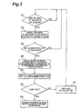
The aggregating flow shown in Fig. 3 will be
described below. First, it is determined whether there
exist a plurality of IP packets on the transmission
queue (step S1). Before a plurality of IP packets are
put on the transmission queue, the determination at
step S1 is repeated. When a plurality of IP packets
exist on the transmission queue, reference is made to
header information of arbitrary two IP packets in the
queue (step S2). Here the arbitrary two IP packets
will be referred to as IP packets 1 ○ and 2 ○.
Next, it is determined whether the packets have a
common route at least in part of their routes (step
S3). Without any common route, the flow transfers to
step S1; with a common route, the IP packets 1 ○ and 2 ○
are compressed and capsuled to create an aggregate
packet (step S4). The aggregate packet thus created
will be referred to as IP packet 3 ○.
Supposing that packets I, II are aggregated at
the router C and are transmitted via the router D to
hosts E, F, the first and second packet compressing
methods of the aggregate packet according to the
present invention will be described below.
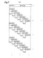
The first packet compressing method will be
described first with reference to Fig. 6, Fig. 7, and
Fig. 8. At the router C, as shown for example in Fig.
7, the packets I, II received from the hosts A, B,
respectively, are compared with bit patterns 1, 2,
3,... acquired from the compression table 18a (cf. Fig.
6), thereby determining whether the packets I, II
include the predetermined bit patterns.
Since the packets are comprised of bit strings of
8-bit (1 byte) units, the bit patterns are desirably
compared while being shifted by one byte each, from the
viewpoint of processing efficiency. A bit pattern,
which is judged to be included in the packets I, II
from the result of the comparison, is converted into a
corresponding code.
Fig. 8 is a diagram conceptually showing a
configuration of a packet compressed by the first
packet compressing method. As shown in Fig. 8, the
data part of the compressed aggregate packet V is
composed of compression information V1 and compressed
data V2. Furthermore, the compression information V1
consists of fields F1 to F9.
The field F1 has a fixed length a common to all
the routers having the aggregating and restoring
functions and stores the number of compressed portions
existing in the data part of the aggregate packet V
(e.g., 4). The field F2 has a fixed length b common to
all the routers having the aggregating and restoring
functions and stores a next field bit count c1 for
declaring the number of bits of the field F3, in light
of the fact that the number of bits of the next field
is a variable length. The field F3 has a variable
length c1 (e.g., 1 byte or 500 bytes) and stores a byte
count d1 from the head of the compressed data V2 to
code1 as a first compressed portion.
Likewise, the fields F4, F6, F8, similar to the
field F2, store next field bit counts c2, c3, c4,
respectively, for declaring the number of bits of the
next field F5, F7, or F9. The fields F5, F7, F9,
similar to the field F3, have variable lengths c2, c3,
c4 and store byte counts d2, d3, d4, respectively, from
the end of a compressed portion (e.g., code1) to a next
compressed portion (e.g., code2).
The fields F5, F7, F9 may be configured to store
byte counts from the head of the compressed data V2 to
the respective compressed portions (e.g., code2, code3,
and code4) as the field F3 was.
In either of these forms, the fields F3, F5, F7,
F9 can be configured in fixed lengths, e.g., of 12
bits; in the case of the fixed lengths, the fields F2,
F4, F6, F8 for declaring the bit counts do not always
have to be provided.
The compressed data V2 is comprised of non-compressed
portions of the byte counts d1, d2, d3, d4
and compressed portions code1, code2, code3, code4 as
given 3-bit data, which are alternately arranged. Each
of the data stored in F1 to F9 is used for specifying a
bit string as a conversion target to a bit pattern
among the compressed data V2 in the operation of
uncompressing the data part of the aggregate packet V
to recover the packets I, II.
Subsequently, the second compressing method will
be described with reference to Fig. 9, and Fig. 10.
The router C detects from the packet II, a data part
common to the packet I and the packet II received from
the respective hosts A, B (which will be hereinafter
referred to as a "common portion"). Specifically, as
shown in Fig. 9, the common portion is searched for by
moving the packet II by one byte each from the position
where the leading portion of the packet I coincides
with the end portion of the packet II, to the position
where the end portion of the packet I coincides with
the leading portion of the packet II. From the
viewpoint of search efficiency, the packet to be moved
is desirably a packet with the number of bits
relatively smaller.
The search is carried out by performing the
exclusive OR operation bit by bit between the packet I
and the packet II. As a result of the research, as
shown in Fig. 9, identical bits between the packet I
and the packet II are expressed as "0" and different
bits as "1." In the present embodiment, the search
ends in finding a common portion with the bit count of
g bytes at the position of f bytes from the leading
portion of the packet II.
Specifically, the process of searching for the
common bit string between the packet I and the packet
II is carried out as follows. Let us suppose herein
that the longer packet out of the two packets to be
aggregated is the packet I and the shorter the packet
II, that the packet length of the packet I is L1 bytes,
and that a value at the k-th bit from the head of the
packet I is B1(k-1) (i.e., the head bit is B1(0) and
the last bit B1(L1*8-1)). It is also supposed that the
packet length of the packet II is L2 bytes and that a
value at the h-th bit from the head of the packet II is
B2(h-1). Furthermore, it is supposed that when the
head of the packet II is not a search target, the
number of bytes in overlapping portions of the packet I
and the packet II is e' and that when the head is a
search target, the number of bytes from the head of the
packet I to the head of the packet II is e.
For an integer e' between 0 inclusive and L2, the
exclusive OR operation is performed between a bit
string B1(0)-B1(8*e'-1) and a bit string B2(8*L2-8*e')-B2(8*L2-1).
If the exclusive OR operation results in
obtaining a bit string including a continuous 0 string
of g bytes at f bytes from the head, a bit string
B1(8*f)-B1(8*f+8*g-1) in the packet I and a bit string
B2(8*L2-8*e'+ 8*f)-B2(8*L2-8*e'+ 8*f+8*g-1) in the packet
II must be a common portion.
For an integer e between 0 inclusive and (L1-L2),
the exclusive OR operation is performed between a bit
string B1(8*e)-B1(8*e+8*L2-1) and a bit string B2(0)-B2(8*L2-1).
When the exclusive OR operation results in
obtaining a bit string including a continuous 0 string
of g bytes at f bytes from the head, a bit string
B1(8*e+8*f)-B1(8*e+8*f+8*g-1) in the packet I and a bit
string B2(8*f)-B2(8*f+8*g-1) in the packet II must be a
common portion.
For an integer e between (L1-L2) inclusive and
L1, the exclusive OR operation is performed between a
bit string B1(8*e)-B1(8*L1-1) and a bit string B2(0)-B2(8*L1-8*e-1).
If the exclusive OR operation results
in obtaining a bit string including a continuous 0
string of g bytes at f bytes from the head, a bit
string B1(8*e+8*f)-B1(8*e+8*f+8*g-1) in the packet I
and a bit string B2(8*f)-B2(8*f+8*g-1) in the packet II
must be a common portion.
Fig. 10 is a diagram schematically showing a
configuration of a packet compressed by the second
packet compressing method. As shown in Fig. 10, the
data part of the compressed aggregate packet V is
composed of compression information V3 and compressed
data V4. Furthermore, the compression information V3
consists of fields F11 to F23.
The field F11 has a fixed length h common to all
the routers having the aggregating and restoring
functions and stores the number of compressed portions
existing in the data part of the aggregate packet V
(e.g., 4). The field F12 has a fixed length i common
to all the routers having the aggregating and restoring
functions and stores a byte count j1 from the head to
the first common portion in the packet I. Likewise,
the field F13 has the fixed length i and stores a byte
count k1 from the head to the first common portion in
the packet II. The field F14 has a fixed length m
common to all the routers having the aggregating and
restoring functions and stores a byte count n1
indicating the number of bits of the first common
portion.
Namely, a common portion of a byte count g is
changed into compression information of a byte count
(i×2+m) as a result of the compression process.
Therefore, a condition for bringing about the
compression effect by the second packet compressing
method is that a bit string having at least the byte
count g meeting the relation of g > i×2+m is selected
as a common portion of a compression target. Namely,
the larger a byte count obtained from subtraction of
(i×2+m) bytes from the byte count of the common
portion, the higher the effect of the compression
process.
Similarly, the fields F15, F18, and F21 have the
fixed length i common to all the routers having the
aggregating and restoring functions and store byte
counts j2, j3, and j4, respectively, from the head to
the second, third, and fourth common portions in the
packet I. Likewise, the fields F16, F19, and F22 have
the fixed length i and store byte counts k2, k3, and
k4, respectively, from the head to the second, third,
and fourth common portions in the packet II. The
fields F17, F20, and F23 have the fixed length m common
to all the routers having the aggregating and restoring
functions and store byte counts n2, n3, and n4,
respectively, indicating the numbers of bits of the
second, third, and fourth common portions.
The compressed data V4 consists of non-compressed
part V41 and compressed part V42, as shown in Fig. 10.
The non-compressed part V41 is equivalent to one packet
(packet I) which is the same packet as that before the
compression, and the compressed part V42 to the other
packet (packet II) without the first to fourth common
portions. Namely, the compressed part V42 is data
corresponding to the difference between the packet I
and the packet II. The data stored in F11 to F23 is
used for specifying the positions where the respective
common portions are to be inserted in the compressed
data V4 in the operation of uncompressing the data part
of the aggregate packet V to recover the packets I, II.
The first and second compressing methods can be
redundantly applied to a single packet. Packets to be
aggregated may also be three or more packets, of
course.
In either case of the above first and second
compressing methods, the compression results in
decreasing the number of bits of the data part of the
aggregate packet V approximately by the number of bits
resulting from subtraction of the compression
information from the total number of bits of the
compressed portions before the compression. However,
if the number of bits decreased by the compression of
the packets to be aggregated is small, the aggregation
and compression can result in increasing the number of
bits contrary. Therefore, the following process is
executed to compare the total number of bits of the
packets I, II with the total number of bits of the
aggregate packet V.
Namely, the bits of the IP packets 1 ○, 2 ○, and 3 ○
(equivalent to the foregoing packets I, II, and V,
respectively) are counted, the count results thereof
are defined as L1, L2, and L3, respectively, and L3 is
compared with (L1+L2) (steps S5, S6). When the
condition of L3 ≤ (L1+L2) is not met as a result of the
comparison, the IP packet 3 ○ is discarded (step S7) and
then the flow goes to step S1. When the condition of
L3 ≤ (L1+L2) is met on the other hand, the IP packets
1 ○ and 2 ○ are discarded and, instead thereof, the IP
packet 3 ○ is routed to an adjacent router on the common
route (step S8).
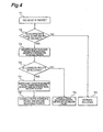
The restoring flow shown in Fig. 4 will be
described below. When an IP packet is received (step
T1), it is determined whether the received IP packet
includes an aggregate flag (step T2). Without the
aggregate flag, the normal routing is carried out (step
T3). With the aggregate flag on the other hand, the
packet is decapsuled (or decomposed) to recover the
original IP packets once (step T4).
For restoring a packet compressed by the first
packet compressing method, it is necessary to perform
an uncompressing process as a preliminary process; in
the uncompressing operation, the router D converts
compressed portions (code1 to code4 in Fig. 8) in the
compressed data into their original bit patterns with
reference to the compression table 18a. In an
uncompressing process carried out prior to the
restoring operation of a packet compressed by the
second packet compressing method, the router D inserts
the data of common portions picked out in the
compressing operation, into the compressed data.
Then reference is made to the destinations of the
respective original packets. As a result of the
reference, it is determined whether the packets have a
common route in their routes (step T5). When they have
no common route, each of the recovered packets is
normally routed and the aggregate packet is discarded
(step T6). On the other hand, when the packets have a
common route in their routes, only the header of the
aggregate packet is changed so that the destination
thereof is an adjacent node (router) on the common
route (step T7). Here the data part is copied. The
aggregate packet created at step T7 is normally routed
and each of the recovered packets is discarded (step
T8).
The presence of the aggregate flag makes it
feasible to readily and quickly determine whether a
packet is an aggregate packet.
A specific routing method in the first embodiment
will be described below with reference to Fig. 1 and
Fig. 5. As shown in Fig. 5, the IP packet format
includes a source's IP address at the head and a
destination IP address subsequent thereto. Thereafter,
an aggregate flag is set as occasion may demand, and
the data part is provided in the last place. In Fig.
1, the host A sends the IP packet I to the host E. In
the IP packet I, as shown in Fig. 5, the source is the
host A and the destination the host E. The host B
sends the IP packet II to the host F. In the IP packet
II, the source is the host B and the destination the
host F.
Receiving the packet I and the packet II, the
router C executes the aggregating flow shown in Fig. 3,
to create the aggregate packet III by its aggregating
function. In the IP packet III, as shown in Fig. 5,
the source is the router C, the destination the router
G, and the aggregate flag is set. The data part stores
the packet I and the difference between the packets I
and II, using the differential compression technology
adopting interframe correlation coding in moving
picture. Since the number of bits of the packet III is
smaller than the number of bits of the packets I, II,
the packet III is routed.
Receiving the aggregate packet III, the router G
at a relay point executes the restoring flow shown in
Fig. 4. Since it is determined therein that the
recovered original packets also have a common route
hereinafter, the recovered packets are discarded. The
aggregate packet is routed to an adjacent router H on
the common route. This aggregate packet has the
structure shown in Fig. 5. Namely, the source is the
router G, the destination the router H, and the
aggregate flag is set. The data part stores the packet
I, and the difference between the packets I and II.
The router H at a relay point operates in much
the same manner as the router G, and sends the
aggregate packet V to the router D. In the aggregate
packet V, as shown in Fig. 5, the source is the router
H, the destination the router D, and the aggregate flag
is set; and the data part stores the packet I, and the
difference between the packets I and II.
Receiving the aggregate packet V, the router D
executes the restoring flow shown in Fig. 4. As shown
in Fig. 4, for example, since the aggregate flag is set
in the aggregate packet V, the restoring operation is
carried out to recover the packet VI (the same data
configuration as the packet I) and the packet VII (the
same data configuration as the packet II). Since the
packet VI and the packet VII have no common route any
longer, the aggregate packet is discarded and the
recovered packets are routed. It is also possible that
a recovered packet is again aggregated with another
packet on the transmission queue as a result of
execution of the aggregating flow. Then the IP packets
VI, VII are sent to the host E and to the host F,
respectively.
In the packet communication system of the first
embodiment, as described above, when tow or more
packets have a common route at least in part of the
routes to their respective terminal addresses, the
information pieces of the packets are aggregated to
create one aggregate packet, which can decrease the
total number of packets transmitted on the network.
The decrease in the total number of packets results in
decreasing the number of references to the routing
table, reducing the processing load, and increasing the
processing speed. As a result, it becomes feasible to
achieve the efficient utilization of the network
resources. Furthermore, it is determined whether the
aggregate packet should be relayed in that state to the
next link, or the two or more original packets should
be recovered from the aggregate packet and be relayed.
When the result of the determination is that the
packets have a common route at least in part of their
routes, the destination address of the aggregate packet
is rewritten so that the destination address of the
aggregate packet is an address of an adjacent router on
the common route, and the aggregate packet is routed,
which can reduce the total number of packets
transmitted on the network.
The above described the case where the receivers
of the aggregate packet V were routers, with reference
to Fig. 1 to Fig. 10, but the present invention can
also be applied to the case where the receivers of the
aggregate packet V are mobile terminals. The following
will describe a process of creating the aggregate
packet V from the packets I, II, using Mobile IPv6
(Internet Protocol Version 6), with reference to Fig.
1, Fig. 11A, Fig. 11B, Fig. 12A, and Fig. 12B. In the
description herein, it is supposed that the aggregate
packet V of the packets I, II is sent from the hosts A,
B via the router C to a mobile host M (not shown).
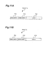
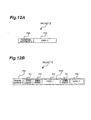
As a premise, the packet I is composed of a basic
IPv6 header P11, a routing header P12, and a data area
P13, as shown in Fig. 11A. An IP address (Care of
address) temporarily used at a foreign subnet by the
mobile terminal is stored as a routing address 1 in the
basic IPv6 header P11. An address specific to the
mobile host M to receive the packet I (Home address) is
stored as a terminal address 2 in the routing header
P12. Here the terminal does not always have to be a
final arriving point of the packet, but it includes a
terminal point of a common route between arbitrary
nodes or hosts. Data 1 as real data is stored in the
data area P13.
The packet II is composed of a basic IPv6 header
P21 and a data area P22, as shown in Fig. 12A. An
address specific to the mobile host M to receive the
packet II is stored as a terminal address 2 in the
basic IPv6 header P21. Data 2 as real data is stored
in the data area P22.
When the packet I and the packet II both arrive
at the router C, the router C aggregates the packets I,
II and adds a terminal address 1 indicating the present
position of the mobile host M to create the aggregate
packet V. The aggregate packet V stores the terminal
address 1 as a routing destination in the basic IPv6
header P51, as shown in Fig. 12B. The packet I and the
packet II are packed in the data area P52.
When the aggregate packet V arrives at the node
indicated by the terminal address 1 (the mobile host
M), the mobile host M creates (or recovers) the packets
I, II from the aggregate packet V. At this time, the
terminal address 1 and the terminal address 2 both are
the address of the mobile host M. Accordingly, the
mobile host M is able to receive the packets I, II
having the terminal address 2 at the head, as well as
the aggregate packet V having the terminal address 1 at
the head. This makes it feasible to perform more
efficient packet transmission while avoiding triangle
routes, as compared with the case where the packet, II
is once capsuled at another node (Home Agent) and is
transferred to the mobile host M.
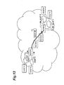
Fig. 13 is a diagram schematically showing a
packet communication system as a second embodiment of
the present invention. In the second embodiment, two
or more IP packets' are capsuled together under one IP
header to create an aggregate packet. The system is
configured on the premise that the routing protocols
such as OSPF and others are active on the network and
that the routers having the aggregating function
preliminarily know the network topology and which node
has the restoring function. It is also possible to
manually set the network topology and the nodes with
the restoring function, for each of the routers having
the aggregating function. The router G in the network
has neither the restoring function nor the aggregating
function. The router H has only the restoring function
by decapsuling. The router C and the router D have
both the aggregating function by capsuling and the
restoring function by decapsuling. Here the
aggregating function is a function of executing the
processing shown in the flowchart of Fig. 15, and the
restoring function a function of executing the
processing shown in the flowchart of Fig. 16. The
router C and the router D having the both functions
execute the aggregating flow on the transmission queue
in parallel with execution of the restoring flow for
each of received packets.
Fig. 14 is a block diagram showing a schematic
configuration of a router having the aggregating
function and the restoring function in the second
embodiment. The present embodiment is different from
the first embodiment in that the router is provided
with an address determining device 70 for determining
whether a destination address extracted agrees with an
address of its own router, instead of the determining
device 6 in the restoring function section 1. The
destination address giving device 10 gives an aggregate
packet a destination address so that the destination
address of the aggregate packet is an address of a
predetermined node having the function of recovering
the two or more original packets from the aggregate
packet. This makes it feasible to designate a
restoring node. The other components are similar to
those in the first embodiment, and thus the description
thereof is omitted herein.
Since the router C and the router D shown in Fig.
13 are provided with the aggregating function and the
restoring function, they have the restoring function
section 1 and the aggregating function section 2 shown
in Fig. 14. Since the router H is provided with only
the restoring function, it has only the restoring
function section 1.
The aggregating flow shown in Fig. 15 will be
described below. First, the router C determines
whether there exist a plurality of IP packets on the
transmission queue (step R1). Before the transmission
queue comes to include a plurality of IP packets, the
determination at step R1 is repeated. On the other
hand, when the transmission queue includes a plurality
of IP packets, reference is made to headers of
arbitrary two IP packets in the queue (step R2). The
arbitrary two IP packets will be referred to as IP
packets 1 ○ and 2 ○, respectively.
It is then determined whether the packets have a
common route in their routes (step R3). When the
packets have no common route in their routes, the flow
transfers to step R1; when the packets have a common
route in their routes, a search is performed for the
most distant node among the restoring nodes present on
the common route (step R4). The most distant router
among the restoring nodes present on the common route
will be referred to hereinafter as an FC (Farthest
Common) router. The router C sends an IP packet with
its destination of the router D being an FC router, so
as to skip the flag reference process and the restoring
process at the routers G, H, thereby increasing the
processing efficiency.
After the search at step R4, it is determined
whether there is an FC router (step R5). If no FC
router exists, the flow transfers to step R1. If there
is an FC router, an aggregate packet is created by
compressing and capsuling the IP packets 1 ○ and 2 ○ (step
R6). This aggregate packet is defined as an IP packet
3 ○ and the destination thereof is the FC router. The
compression for the aggregate packet is implemented by
applying the first or second packet compressing method
described referring to Fig. 6 to Fig. 10, or the both.
Then the bit counts of the IP packets 1 ○, 2 ○, and
3 ○ are defined as L1, L2, and L3, respectively, and L3
is compared with (L1+L2) (step R7). When the
comparison results in not meeting the condition of L3 ≤
(L1+L2), the IP packet 3 ○ is discarded (step R9) and
the flow transfers to step R1. On the other hand, when
the condition of L3 ≤ (L1+L2) is met, the IP packets 1 ○
and 2 ○ are discarded and, instead thereof, the IP
packet 3 ○ is routed to the FC router (step R10).
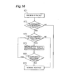
The restoring flow shown in Fig. 16 will be
described below. When an IP packet is received (step
ST1), it is determined whether the received IP packet
includes an aggregate flag (step ST2). Without the
aggregate flag, the normal routing is carried out (step
ST6). With the aggregate flag on the other hand, it is
determined whether the destination of the IP packet is
its own router (step ST3). When the destination of the
IP packet is not its own router, the normal routing is
performed (step ST6). When the destination of the IP
packet is its own router, the packet is decapsuled (or
decomposed) to recover the original IP packets (step
ST4). It is then determined whether each recovered IP
packet is one with an aggregate flag (step ST5). When
the IP packet includes no aggregate flag, the normal
routing is performed (step ST6). On the other hand,
when the IP packet includes the aggregate flag, the
flow goes to step ST3.
A specific routing process in the second
embodiment will be described below with reference to
Fig. 13 and Fig. 17. As shown in Fig. 17, the IP
packet format has a source's IP address at the head and
a destination IP address subsequent thereto.
Thereafter, an aggregate flag is set as occasion may
demand, and the data portion is provided in the last
place. In Fig. 13, the host A sends the IP packet I to
the host E. In the IP packet I, as shown in Fig. 17,
the source is the host A and the destination the host
E. The host B sends the IP packet II to the host F.
In the IP packet II, the source is the host B and the
destination the host F.
Receiving the packet I and the packet II, the
router C executes the aggregating flow shown in Fig.
15, to create an aggregate packet III by its
aggregating function. As shown in Fig. 17, the data
part stores the packet I, and the difference between
the packets I and II, using the differential
compression technology adopting the interframe
correlation coding in moving picture. In the header
part the aggregate flag is set and the router D being
the FC router is designated as a destination node of
the aggregate packet. Since the number of bits of the
packet III is smaller than that of the packets I, II,
the packet III is routed.
This results in restoring the aggregate packet
only at the designated node. Namely, the nodes other
than the designated node perform the normal routing, so
as to avoid performing dispensable restoring
processing, whereby the repeating processing can be
made more efficient.
The router G at a relay point does not have the
restoring function and thus performs the normal routing
of this packet III. This router G without the
restoring function can never be a terminal of the
packet capsuled by the router C.
Receiving the aggregate packet III, the router H
at a relay point executes the restoring flow.
According to Fig. 16, though the aggregate flag is set
in the packet III, the normal routing is carried out
eventually, because the destination address is not the
router G.
Receiving the aggregate packet III, the router D
executes the restoring flow shown in Fig. 16. Since
the aggregate flag is set in the packet III and the
destination address is the router D (its own router),
the restoring operation is carried out to recover the
packet IV (the same data configuration as the packet I)
and the packet V (the same data configuration as the
packet II), as shown in Fig. 16. Here each of the
packet IV and the aggregate packet V can be again
aggregated with another packet. Then the IP packets
IV, V are transmitted to the host E and to the host F,
respectively.
As described above, the packet communication
system in the second embodiment is configured to
aggregate two or more packets to replace them with a
single aggregate packet and further compress the
aggregate packet, which decreases the total number of
packets and the total amount of information transmitted
on the network, thereby achieving the efficient
utilization of the network resources.
Fig. 18 is a diagram schematically showing a
packet communication system as a third embodiment of
the present invention. In the above-described first
embodiment and second embodiment, the aggregate IP
packet was created by capsuling of two IP packets, but
it is also possible to create an aggregate Ethernet
(registered trademark) frame from two IP packets
without use of the capsuling technology. In the third
embodiment, an aggregate Ethernet frame is created from
two IP packets. The system is based on the premise
that the routing protocols are used on the network, as
in the conventional Internet.
Here the routers A and B have the aggregating
function of an Ethernet level and all the routers on
the network have the restoring function. The
aggregating function of the Ethernet level herein is a
function of executing the processing shown in the
flowchart of Fig. 19. The restoring function of the
Ethernet level is a function of identifying an
aggregate flag of an aggregate Ethernet frame and
extracting two IP packets from the frame. A node
having these two functions is configured to execute the
restoring function for each of received Ethernet frames
and carry out the aggregating flow on the transmission
queue in parallel therewith.
The aggregating flow shown in Fig. 19 will be
described below. It is first determined whether there
exist a plurality of Ethernet frames on the
transmission queue (step W1). Before the transmission
queue comes to include a plurality of Ethernet frames,
the determination at step W1 is repeated. On the other
hand, when the transmission queue includes a plurality
of Ethernet frames, a comparison is made between
destination MAC addresses of arbitrary two Ethernet
frames 1 ○ and 2 ○ in the queue (step W2). It is then
determined whether the MAC addresses agree with each
other (step W3). When they disagree, the flow goes to
step W1. When the MAC addresses agree with each other
on the other hand, an Ethernet frame 3 ○ is created in a
configuration wherein two upper-layer packets in the
data parts of the Ethernet frames 1 ○ and 2 ○ both are
stored in its data part and a common next hop MAC
address is designated as a destination (step W4). It
is next determined whether the Ethernet frame 3 ○ is
within MTU (Maximum Transmission Unit) (step W5). When
it is over MTU, the Ethernet frame 3 ○ is discarded
(step W6) and the flow transfers to step W1. When the
Ethernet frame 3 ○ is within MTU at step W5 on the other
hand, the Ethernet frames 1 ○ and 2 ○ are discarded and,
instead thereof, the Ethernet frame 3 ○ is routed to the
next hop (step W7).
A specific routing process in the third
embodiment will be described below with reference to
Fig. 18 and Fig. 20. As shown in Fig. 20, the format
of the Ethernet frame includes a destination MAC
address at the head and a source's MAC address
subsequent thereto. Thereafter, an aggregate flag is
set according to necessity, and the data part is
provided in the last place. The data part stores a
source's IP address and a destination IP address in the
order stated.
Let us suppose that a host A1 on an Ethernet link
A sends an Ethernet frame I with the data part
including an IP packet I sent to a host B1 on an
Ethernet link B, and a host A2 on the link A sends an
Ethernet frame II with the data part including an IP
packet II sent to a host B2 on the link B. Receiving
the two Ethernet frames, the router A once creates an
Ethernet frame III for sending the IP packet I to the
router B and an Ethernet frame IV for sending the IP
packet II to the router B.
When these two frames are created on the queue,
the router A executes the aggregating flow. Namely,
the router A creates an Ethernet header with the
destination of the router B which is a common
destination address, and stores the IP packet I and the
IP packet II in the data part. An Ethernet frame V
thus created is shown in Fig. 20. The Ethernet frame V
is relayed through an Ethernet link C to the router B.
On this occasion, in the Ethernet frame format there
exists a flag set for an aggregate packet in the
Ethernet header, and an aggregate flag is thus present,
because the Ethernet frame V is an "aggregate packet."
Receiving the Ethernet frame V, the router B
identifies the aggregate flag and extracts the two IP
packet I and IP packet II from the data part.
Subsequently, the router B places an Ethernet frame VI
with the host B1 as a destination MAC address and an
Ethernet frame VII with the host B2 as a destination
MAC address on the queue. The aggregating flow can
also be executed on this queue, but the aggregation is
not carried out in fact, because the destinations of
the Ethernet frames disagree.
The IP packets I, II are carried by the
respective Ethernet frames VI, VII to be delivered to
the hosts B1, B2.
As described above, the packet communication
system in the third embodiment is configured to perform
the aggregation of Ethernet frames, whereby it is
feasible to reduce the overhead and achieve maximum
utilization of MTU of each link.
In the last place, the following will describe a
program for implementing the routing technology
according to the present invention and a computer-readable
recording medium (which will be referred to
hereinafter simply as a "recording medium") in which
the program is recorded. The recording medium is a
medium capable of inducing state changes of energy such
as magnetism, light, electricity, or the like according
to the' description contents of the program against a
reading device provided in the hardware resources of
general-purpose computers and others and transmitting
the description contents of the program to the reading
device in the form of signals corresponding to the
state changes. Such recording media can be, for
example, those detachably mounted on computers,
(including mobile computers) like IC cards, magnetic
disks, optical disks, and magnetooptical disks, and can
also be HD (Hard Disk) fixedly built in computers,
nonvolatile semiconductor memories such as firmware or
the like integrally secured in the computers, and so
on.
The above program may be configured so that part
or the whole thereof is received by a router or a node
according to the present invention through transmission
media such as a communication line and others from
another device and is recorded therein. Contrary, the
above program may also be configured so that it is
transmitted from a router or a node according to the
present invention through the transmission media to
another device to be installed therein.
According to the present invention, as described
above, when two or more packets have a common route at
least in part of their routes to respective terminal
addresses, the information pieces of the packets are
aggregated to create one aggregate packet. This can
reduce the total number of packets transmitted on the
network. The decrease in the total number of packets
results in decreasing the number of references to the
routing table and reducing the processing load, thereby
increasing the processing speed. As a result, it
becomes feasible to achieve the efficient utilization
of the network resources.
Claims (24)
- A routing method of, based on a destination address given to a packet, routing said packet, said method comprising:a step of extracting a destination address of a packet;a step of extracting two or more packets having a common route at least in part of routes to their respective terminals, from a plurality of packets, based on their respective destination addresses thus extracted;a step of aggregating the two or more packets having the common route at least in part of the routes to create an aggregate packet including information of each of the packets;a step of giving said aggregate packet a destination address so that the destination address of said aggregate packet is an address of an adjacent node on said common route; anda step of routing said aggregate packet, based on said destination address.
- A routing method of, based on a destination address given to a packet, routing said packet, said method comprising:a step of extracting a destination address of a packet;a step of recovering a plurality of original packets from an aggregate packet in which the plurality of packets are aggregated;a step of determining whether said recovered packets have a common route at least in part of routes to their respective terminals, based on destination addresses of the respective packets; anda step of performing routing in such a way that when the result of the determination is that the packets have the common route at least in part of the routes, a destination address of said aggregate packet is rewritten so that the destination address of said aggregate packet is an address of an adjacent node on said common route, and the aggregate packet is routed based on the destination address, or in such a way that when the packets have no common route, said recovered packets are routed based on their respective destination addresses.
- A routing method of, based on a destination address given to a packet, routing said packet, said method comprising:a step of extracting a destination address of a packet;a step of extracting two or more packets having a common route at least in part of routes to their respective terminals, from a plurality of packets, based on their respective destination addresses thus extracted;a step of aggregating the two or more packets having the common route at least in part of the routes to create an aggregate packet including information of each of the packets;a step of giving said aggregate packet a destination address so that the destination address of said aggregate packet is an address of a predetermined node having a function of recovering the two or more original packets from said aggregate packet; anda step of routing said aggregate packet, based on said destination address thus determined.
- A routing method of, based on a destination address given to a packet, routing said packet, said method comprising:a step of extracting a destination address of a packet;a step of determining whether said destination address extracted agrees with its own address;a step of recovering a plurality of original packets from an aggregate packet in which the plurality of packets are aggregated, when the result of the determination is that said destination address extracted agrees with its own address; anda step of routing each of said recovered packets, or said aggregate packet having the destination address disagreeing with its own address, based on the destination address.
- The routing method according to Claim 1 or Claim 3, comprising a step of setting an aggregate flag indicating an aggregate packet, in header information of said aggregate packet.
- The routing method according to Claim 1 or Claim 3, comprising:a step of comparing the total number of bits of the two or more packets having the common route at least in part of the routes, with the number of bits of said aggregate packet; anda step of routing said aggregate packet, based on the destination address thereof, only when the result of the comparison is that the number of bits of said aggregate packet is smaller than the total number of bits of said two or more packets.
- The routing method according to Claim 1 or Claim 3, wherein targets of aggregation are only packets buffered on a transmission queue.
- A node for, based on a destination address given to a packet, routing said packet, said node comprising:destination address extracting means for extracting a destination address of a packet;common-route packet extracting means for extracting two or more packets having a common route at least in part of routes to their respective terminals, from a plurality of packets, based on their respective destination addresses thus extracted;aggregate packet creating means for aggregating the two or more packets having the common route at least in part of the routes to create an aggregate packet including information of each of the packets;destination address giving means for giving said aggregate packet a destination address so that the destination address of said aggregate packet is an address of an adjacent node on said common route; andaggregate packet routing means for routing said aggregate packet, based on said destination address.
- A node for, based on a destination address given to a packet, routing said packet, said node comprising:destination address extracting means for extracting a destination address of a packet;recovering means for recovering a plurality of original packets from an aggregate packet in which the plurality of packets are aggregated;determining means for determining whether said recovered packets have a common route at least in part of routes to their respective terminals, based on destination addresses of the respective packets; andpacket routing means for performing routing in such a way that when the result of the determination is that the packets have the common route at least in part of the routes, a destination address of said aggregate packet is rewritten so that the destination address of said aggregate packet is an address of an adjacent node on said common route, and the aggregate packet is routed based on the destination address, or in such a way that when the packets have no common route, said recovered packets are routed based on their respective destination addresses.
- A node for, based on a destination address given to a packet, routing said packet, said node comprising:destination address extracting means for extracting a destination address of a packet;common-route packet extracting means for extracting two or more packets having a common route at least in part of routes to their respective terminals, from a plurality of packets, based on their respective destination addresses thus extracted;aggregate packet creating means for aggregating the two or more 'packets having the common route at least in part of the routes to create an aggregate packet including information of each of the packets;destination address giving means for giving said aggregate packet a destination address so that the destination address of said aggregate packet is an address of a predetermined node having a function of recovering the two or more original packets from said aggregate packet; andaggregate packet routing means for routing said aggregate packet, based on said destination address thus determined.
- A node for, based on a destination address given to a packet, routing said packet, said node comprising:destination address extracting means for extracting a destination address of a packet;address determining means for determining whether said destination address extracted agrees with its own address;recovering means for recovering a plurality of original packets from an aggregate packet in which the plurality of packets are aggregated, when the result of the determination is that said destination address extracted agrees with its own address; andpacket routing means for routing each of said recovered packets, or said aggregate packet having the destination address disagreeing with its own address, based on the destination address.
- The node according to Claim 8 or Claim 10, comprising aggregate flag setting means for setting an aggregate flag indicating an aggregate packet, in header information of said aggregate packet.
- The node according to Claim 8 or Claim 10, comprising:wherein said aggregate packet routing means routes said aggregate packet, based on the destination address thereof, only when the result of the comparison is that the number of bits of said aggregate packet is smaller than the total number of bits of said two or more packets.number-of-bits comparing means for comparing the total number of bits of the two or more packets having the common route at least in part of the routes, with the number of bits of said aggregate packet;
- The node according to Claim 8 or Claim 10, wherein targets of aggregation are only packets buffered on a transmission queue.
- A packet communication system comprising a host for sending a packet; the node as set forth in one of Claims 8 to 14, for relaying said packet; and a host for receiving said packet.
- A program of, based on a destination address given to a packet, routing said packet, said program being configured to make a communication device execute the following processes:a process of extracting a destination address of a packet;a process of extracting two or more packets having a common route at least in part of routes to their respective terminals, from a plurality of packets, based on their respective destination addresses thus extracted;a process of aggregating the two or more packets having the common route at least in part of the routes to create an aggregate packet including information of each of the packets;a process of giving said aggregate packet a destination address so that the destination address of said aggregate packet is an address of an adjacent node on said common route; anda process of routing said aggregate packet, based on said destination address.
- A program of, based on a destination address given to a packet, routing said packet, said program being configured to make a. communication device execute the following processes:a process of extracting a destination address of a packet;a process of recovering a plurality of original packets from an aggregate packet in which the plurality of packets are aggregated;a process of determining whether said recovered packets have a common route at least in part of routes to their respective terminals, based on destination addresses of the respective packets; anda process of performing routing in such a way that when the result of the determination is that the packets have the common route at least in part of the routes, a destination address of said aggregate packet is rewritten so that the destination address of s.aid aggregate packet is an address of an adjacent node on said common route, and the aggregate packet is routed based on the destination address, or in such a way that when the packets have no common route, said recovered packets are routed based on their respective destination addresses.
- A program of, based on a destination address given to a packet, routing said packet, said program being configured to make a communication device execute the following processes:a process of extracting a destination address of a packet;a process of extracting two or more packets having a common route at least in part of routes to their respective terminals, from a plurality of packets, based on their respective destination addresses thus extracted;a process of aggregating the two or more packets having the common route at least in part of the routes to create an aggregate packet including information of each of the packets;a process of giving said aggregate packet a destination address so that the destination address of said aggregate packet is an address of a predetermined node having a function of recovering the two or more original packets from said aggregate packet; anda process of routing said aggregate packet, based on said destination address thus determined.
- A program of, based on a destination address given to a packet, routing said packet, said program being configured to make a communication device execute the following processes:a process of extracting a destination address of a packet;a process of determining whether said destination address extracted agrees with its own address;a process of recovering a plurality of. original packets from an aggregate packet in which the plurality of packets are aggregated, when the result of the determination is that said destination address extracted agrees with its own address; anda process of routing each of said recovered packets, or said aggregate packet having the destination address disagreeing with its own address, based on the destination address.
- A computer-readable recording medium in which the program as set forth in one of Claims 16 to 19 is recorded.
- The routing method according to Claim 5, further comprising a step of compressing said aggregate packet by converting a bit pattern included in said aggregate packet, into a predetermined code.
- The routing method according to Claim 5, further comprising a step of compressing said aggregate packet by picking out a common bit string included in said plurality of packets, from at least one packet out of said two or more packets.
- The node according to Claim 12, further comprising aggregate packet compressing means for compressing said aggregate packet by converting a bit pattern included in said aggregate packet, into a predetermined code.
- The node according to Claim 12, further comprising aggregate packet compressing means for compressing said aggregate packet by picking out a common bit string included in said plurality of packets, from at least one packet out of 'said two or more packets.
Applications Claiming Priority (3)
| Application Number | Priority Date | Filing Date | Title |
|---|---|---|---|
| JP2001197216 | 2001-06-28 | ||
| JP2001197216 | 2001-06-28 | ||
| PCT/JP2002/006616 WO2003003673A1 (en) | 2001-06-28 | 2002-06-28 | Routing method, node, packet communication system, program, and recording medium |
Publications (2)
| Publication Number | Publication Date |
|---|---|
| EP1326387A1 true EP1326387A1 (en) | 2003-07-09 |
| EP1326387A4 EP1326387A4 (en) | 2006-06-07 |
Family
ID=19034860
Family Applications (1)
| Application Number | Title | Priority Date | Filing Date |
|---|---|---|---|
| EP02738885A Withdrawn EP1326387A4 (en) | 2001-06-28 | 2002-06-28 | ROUTING METHOD, NODE, PACKET COMMUNICATION SYSTEM, PROGRAM, AND RECORDING MEDIUM |
Country Status (6)
| Country | Link |
|---|---|
| US (1) | US7301948B2 (en) |
| EP (1) | EP1326387A4 (en) |
| JP (1) | JP3778912B2 (en) |
| KR (1) | KR100496217B1 (en) |
| CN (1) | CN100418326C (en) |
| WO (1) | WO2003003673A1 (en) |
Families Citing this family (24)
| Publication number | Priority date | Publication date | Assignee | Title |
|---|---|---|---|---|
| US7983239B1 (en) | 2003-01-07 | 2011-07-19 | Raytheon Bbn Technologies Corp. | Systems and methods for constructing a virtual model of a multi-hop, multi-access network |
| US7525994B2 (en) * | 2003-01-30 | 2009-04-28 | Avaya Inc. | Packet data flow identification for multiplexing |
| US7881229B2 (en) | 2003-08-08 | 2011-02-01 | Raytheon Bbn Technologies Corp. | Systems and methods for forming an adjacency graph for exchanging network routing data |
| US7545813B2 (en) * | 2003-08-26 | 2009-06-09 | Teknovus, Inc. | Method and apparatus for registering multiple remote nodes in an ethernet passive optical network |
| US7606927B2 (en) * | 2003-08-27 | 2009-10-20 | Bbn Technologies Corp | Systems and methods for forwarding data units in a communications network |
| US8166204B2 (en) * | 2003-08-29 | 2012-04-24 | Raytheon Bbn Technologies Corp. | Systems and methods for automatically placing nodes in an ad hoc network |
| US8718089B2 (en) * | 2003-09-08 | 2014-05-06 | Toshiba America Research Inc. | Aggregation and fragmentation of multiplexed downlink packets |
| US7680100B1 (en) | 2004-09-30 | 2010-03-16 | Avaya Inc. | Internet protocol appliance manager |
| US7561573B2 (en) | 2005-03-23 | 2009-07-14 | Fujitsu Limited | Network adaptor, communication system and communication method |
| JP4532352B2 (en) * | 2005-06-10 | 2010-08-25 | 株式会社ネクストマジック | Communication device |
| US20070201440A1 (en) * | 2006-02-28 | 2007-08-30 | Nec Laboratories America, Inc. | Improved voic-over-internet-protocol method |
| JP4572173B2 (en) * | 2006-03-17 | 2010-10-27 | 株式会社トヨタIt開発センター | Wireless communication apparatus, wireless communication method, and route information table creation method |
| US20070242676A1 (en) * | 2006-04-13 | 2007-10-18 | Corrigent Systems Ltd. | Interface between a synchronous network and high-speed ethernet |
| WO2007144702A1 (en) * | 2006-06-13 | 2007-12-21 | Freescale Semiconductor, Inc. | Method for processing information fragments and a device having information fragment processing capabilities |
| JP4899664B2 (en) * | 2006-06-28 | 2012-03-21 | 富士通株式会社 | Communication device, address learning method, and address learning program |
| TWI382718B (en) * | 2007-08-30 | 2013-01-11 | A method and a system of wireless communication for mobile voice data | |
| US7760629B2 (en) * | 2007-09-04 | 2010-07-20 | Cisco Technology, Inc. | Aggregate data frame generation |
| EP2073459A1 (en) * | 2007-12-17 | 2009-06-24 | Alcatel-Lucent Deutschland AG | Transmission via a burst or frame switched network with timing preservation of the transmitted client packets |
| US8634316B2 (en) * | 2010-10-19 | 2014-01-21 | At&T Intellectual Property I, L.P. | Methods and apparatus to utilize route aggregation for exchanging routes in a communication network |
| US9065726B2 (en) | 2010-10-19 | 2015-06-23 | At&T Intellectual Property I, L.P. | Methods and apparatus to utilize route parameter sets for exchanging routes in a communication network |
| KR101188922B1 (en) | 2010-12-23 | 2012-10-08 | 숭실대학교산학협력단 | Node comprised in wireless network and method for generating address of the same |
| US9401853B2 (en) | 2013-09-24 | 2016-07-26 | International Business Machines Corporation | Determining sampling rate from randomly sampled events |
| US9203711B2 (en) * | 2013-09-24 | 2015-12-01 | International Business Machines Corporation | Port mirroring for sampling measurement of network flows |
| JP7163093B2 (en) * | 2018-07-26 | 2022-10-31 | 株式会社東芝 | Broker device, communication system, communication method, and program |
Family Cites Families (11)
| Publication number | Priority date | Publication date | Assignee | Title |
|---|---|---|---|---|
| JPS62279400A (en) * | 1986-05-29 | 1987-12-04 | 沖電気工業株式会社 | Voice recognition |
| JPS63197148A (en) | 1987-02-12 | 1988-08-16 | Mitsubishi Electric Corp | Packet exchange |
| DE69634401T2 (en) * | 1996-03-08 | 2005-12-29 | Ntt Docomo, Inc. | SYSTEM AND METHOD FOR SHORT CELL MULTIPLEX ATM TRANSMISSION |
| JP2000209228A (en) * | 1999-01-19 | 2000-07-28 | Nippon Telegr & Teleph Corp <Ntt> | IP packet transfer method |
| EP1032165A1 (en) * | 1999-02-26 | 2000-08-30 | International Business Machines Corporation | Method of assembling segmented frames of data transmitted over a backbone |
| JP3391291B2 (en) * | 1999-03-30 | 2003-03-31 | 日本電気株式会社 | Lightwave network data communication system |
| WO2000072532A1 (en) * | 1999-05-24 | 2000-11-30 | Rutgers, The State University Of New Jersey | System and method for network packet reduction |
| JP3593921B2 (en) * | 1999-06-01 | 2004-11-24 | 日本電気株式会社 | Packet transfer method and apparatus |
| US6385757B1 (en) * | 1999-08-20 | 2002-05-07 | Hewlett-Packard Company | Auto design of VLIW processors |
| US6614808B1 (en) * | 1999-09-02 | 2003-09-02 | International Business Machines Corporation | Network packet aggregation |
| US6359574B1 (en) * | 2001-01-22 | 2002-03-19 | Proxell Systems Ltd. | Method for identifying longest common substrings |
-
2002
- 2002-06-28 JP JP2003509724A patent/JP3778912B2/en not_active Expired - Fee Related
- 2002-06-28 EP EP02738885A patent/EP1326387A4/en not_active Withdrawn
- 2002-06-28 WO PCT/JP2002/006616 patent/WO2003003673A1/en not_active Ceased
- 2002-06-28 US US10/362,366 patent/US7301948B2/en not_active Expired - Fee Related
- 2002-06-28 KR KR10-2003-7002866A patent/KR100496217B1/en not_active Expired - Fee Related
- 2002-06-28 CN CNB028021347A patent/CN100418326C/en not_active Expired - Fee Related
Also Published As
| Publication number | Publication date |
|---|---|
| US7301948B2 (en) | 2007-11-27 |
| US20030179751A1 (en) | 2003-09-25 |
| JPWO2003003673A1 (en) | 2004-10-21 |
| EP1326387A4 (en) | 2006-06-07 |
| WO2003003673A1 (en) | 2003-01-09 |
| KR100496217B1 (en) | 2005-06-21 |
| CN100418326C (en) | 2008-09-10 |
| KR20040014965A (en) | 2004-02-18 |
| CN1463523A (en) | 2003-12-24 |
| JP3778912B2 (en) | 2006-05-24 |
Similar Documents
| Publication | Publication Date | Title |
|---|---|---|
| US7301948B2 (en) | Routing method, node, packet communication system, program, and recording medium | |
| JP3880404B2 (en) | MPLS network system | |
| JP3963728B2 (en) | Spanning tree bypass method and apparatus | |
| US7362709B1 (en) | Agile digital communication network with rapid rerouting | |
| JP4038223B2 (en) | Packet transfer method and apparatus | |
| JP4057615B2 (en) | User MAC frame transfer method, edge transfer device, and program | |
| JP4074268B2 (en) | Packet transfer method and transfer device | |
| US7590119B2 (en) | Method and apparatus for context-based prefix updates in border gateway protocol | |
| US7308001B2 (en) | Fibre channel frame batching for IP transmission | |
| US20090052317A1 (en) | Ring Network System, Failure Recovery Method, Failure Detection Method, Node and Program for Node | |
| US20070086362A1 (en) | Network management method and communications network system | |
| JP2021526339A (en) | Data packet detection methods, devices, and systems | |
| CN110601983A (en) | Method and system for forwarding routing without sensing source of protocol | |
| WO2004075482A1 (en) | Network system, learning bridge node, learning method, and program thereof | |
| JP2016517198A (en) | Improved acknowledgment and retransmission mechanism | |
| WO2012053540A1 (en) | Communication system, control apparatus, configuration method for processing rules, and program | |
| JP2010528505A (en) | Ethernet protection switching system | |
| JPH0630004A (en) | How to drop unwanted data packets from the communication network | |
| CN113285878B (en) | Load sharing method and first network equipment | |
| CN111669422A (en) | Message transmission method and device | |
| JP4120356B2 (en) | Extended VLAN tag SWAP method | |
| CN117376233A (en) | Data processing methods, devices and systems | |
| CN111447131B (en) | Message de-encapsulation method and device and message encapsulation method and device | |
| WO2024007939A1 (en) | Packet processing method, network device, and communication system | |
| CN101171802B (en) | Network node, network, method for generating correspondence for transmitting information in network |
Legal Events
| Date | Code | Title | Description |
|---|---|---|---|
| PUAI | Public reference made under article 153(3) epc to a published international application that has entered the european phase |
Free format text: ORIGINAL CODE: 0009012 |
|
| 17P | Request for examination filed |
Effective date: 20030321 |
|
| AK | Designated contracting states |
Designated state(s): AT BE CH CY DE DK ES FI FR GB GR IE IT LI LU MC NL PT SE TR |
|
| A4 | Supplementary search report drawn up and despatched |
Effective date: 20060508 |
|
| 17Q | First examination report despatched |
Effective date: 20090514 |
|
| STAA | Information on the status of an ep patent application or granted ep patent |
Free format text: STATUS: THE APPLICATION HAS BEEN WITHDRAWN |
|
| 18W | Application withdrawn |
Effective date: 20110304 |